

PACOM PDR420 User Manual

Four-Channel Digital Video Recorder
i
WARNING
RISK OF ELECTRIC SHOCK
DO NOT OPEN
WARNING: TO REDUCE THE RISK OF ELECTRIC SHOCK,
DO NOT REMOVE COVER (OR BACK).
NO USER-SERVICEABLE PARTS INSIDE.
REFER SERVICING TO QUALIFIED
SERVICE PERSONNEL.
The lightning flash with arrowhead symbol, within an equilateral triangle, is intended to alert
the user to the presence of uninsulated "dangerous voltage" within the product’s enclosure
that may be of sufficient magnitude to constitute a risk of electric shock.
The exclamation point within an equilateral triangle is intended to alert the user to the
presence of important operating and maintenance (servicing) instructions in the literature
accompanying the appliance.
COMPLIANCE NOTICE OF FCC:
THIS EQUIPMENT HAS BEEN TESTED AND FOUND TO COMPLY WITH THE LIMITS FOR A CLASS A DIGITAL
DEVICE, PURSUANT TO PART 15 OF THE FCC RULES. THESE LIMITS ARE DESIGNED TO PROVIDE
REASONABLE PROTECTION AGAINST HARMFUL INTERFERENCE WHEN THE EQUIPMENT IS OPERATED
IN A COMMERCIAL ENVIRONMENT. THIS EQUIPMENT GENERATES, USES, AND CAN RADIATE RADIO
FREQUENCY ENERGY AND IF NOT INSTALLED AND USED IN ACCORDANCE WITH THE INSTRUCTION
MANUAL, MAY CAUSE HARMFUL INTERFERENCE TO RADIO COMMUNICATIONS. OPERATION OF THIS
EQUIPMENT IN A RESIDENTIAL AREA IS LIKELY TO CAUSE HARMFUL INTERFERENCE, IN WHICH CASE
USERS WILL BE REQUIRED TO CORRECT THE INTERFERENCE AT THEIR OWN EXPENSE.
WARNING: CHANGES OR MODIFICATIONS NOT EXPRESSLY APPROVED BY THE PARTY RESPONSIBLE
FOR COMPLIANCE COULD VOID THE USER’S AUTHORITY TO OPERATE THE EQUIPMENT.
THIS CLASS OF DIGITAL APPARATUS MEETS ALL REQUIREMENTS OF THE CANADIAN
INTERFERENCE-CAUSING EQUIPMENT REGULATIONS.
The information in this manual is believed to be accurate as of the date of publication. IDIS is not responsible for any
problems resulting from the use thereof. The information contained herein is subject to change without notice.
Revisions or new editions to this publication may be issued to incorporate such changes.

User’s Manual
ii
Important Safeguards
1. Read Instructions
All the safety and operating instructions should be read before the
appliance is operated.
2. Retain Instructions
The safety and operating instructions should be retained for future
reference.
3. Cleaning
Unplug this equipment from the wall outlet before cleaning it. Do not
use liquid aerosol cleaners. Use a damp soft cloth for cleaning.
4. Attachments
Never add any attachments and/or equipment without the approval of
the manufacturer as such additions may result in the risk of fire, electric
shock or other personal injury.
5. Water and/or Moisture
Do not use this equipment near water or in contact with water.
6. Placing and Accessories
Do not misplace this equipment other than upright position. This
equipment has an open frame SMPS (Switching Mode Power Supply),
which may cause a fire or electric shock if anything is inserted into the
unit through the ventilation holes on the side of the equipment.
Do not place this equipment on an unstable cart, stand or table. The
equipment may fall, causing serious injury to a child or adult, and
serious damage to the equipment.
This equipment and cart combination should be moved with care.
Quick stops, excessive force, and uneven surfaces may cause the
equipment and cart combination to overturn.
7. Power Sources
This equipment should be operated only from the type of power source
indicated on the marking label. If you are not sure of the type of power,
please consult your equipment dealer or local power company.
8. Power Cords
Operator or installer must remove power and TNT connections before
handling the equipment.
9. Lightning
For added protection for this equipment during a lightning storm, or
when it is left unattended and unused for long periods of time, unplug it
from the wall outlet and disconnect the antenna or cable system. This
will prevent damage to the equipment due to lightning and power-line
surges.
10. Overloading
Do not overload wall outlets and extension cords as this can result in
the risk of fire or electric shock.
11. Objects and Liquids
Never push objects of any kind through openings of this equipment as
they may touch dangerous voltage points or short out parts that could
result in a fire or electric shock. Never spill liquid of any kind on the
equipment.
12. Servicing
Do not attempt to service this equipment yourself. Refer all servicing
to qualified service personnel.
13. Damage requiring Service
Unplug this equipment from the wall outlet and refer servicing to
qualified service personnel under the following conditions:
A. When the power-supply cord or the plug has been damaged.
B. If liquid is spilled, or objects have fallen into the equipment.
C. If the equipment has been exposed to rain or water.
D. If the equipment does not operate normally by following the
operating instructions, adjust only those controls that are covered by
the operating instructions as an improper adjustment of other
controls may result in damage and will often require extensive work
by a qualified technician to restore the equipment to its normal
operation.
E. If the equipment has been dropped, or the cabinet damaged.
F. When the equipment exhibits a distinct change in performance —
this indicates a need for service.
14. Replacement Parts
When replacement parts are required, be sure the service technician has
used replacement parts specified by the manufacturer or that have the
same characteristics as the original part. Unauthorized substitutions
may result in fire, electric shock or other hazards.
15. Safety Check
Upon completion of any service or repairs to this equipment, ask the
service technician to perform safety checks to determine that the
equipment is in proper operating condition.
16. Field Installation
This installation should be made by a qualified service person and
should conform to all local codes.
17. Correct Batteries
Warning: Risk of explosion if battery is replaced by an incorrect type.
Dispose of used batteries according to the instructions.
18. Tmra
A manufacturer’s maximum recommended ambient temperature
(Tmra) for the equipment must be specified so that the customer and
installer may determine a suitable maximum operating environment
for the equipment.
19. Elevated Operating Ambient Temperature
If installed in a closed or multi-unit rack assembly, the operating
ambient temperature of the rack environment may be greater than room
ambient. Therefore, consideration should be given to installing the
equipment in an environment compatible with the manufacturer’s
maximum rated ambient temperature (Tmra).
20. Reduced Air Flow
Installation of the equipment in the rack should be such that the amount
of airflow required for safe operation of the equipment is not
compromised.
21. Mechanical Loading
Mounting of the equipment in the rack should be such that a hazardous
condition is not caused by uneven mechanical loading.
22. Circuit Overloading
Consideration should be given to connection of the equipment to
supply circuit and the effect that overloading of circuits might have on
over current protection and supply wiring. Appropriate consideration
of equipment nameplate ratings should be used when addressing this
concern.
23. Reliable Earthing (Grounding)
Reliable grounding of rack mounted equipment should be maintained.
Particular attention should be given to supply connections other than
direct connections to the branch circuit (e.g., use of power strips).

Four-Channel Digital Video Recorder
iii
Table of Contents
Chapter 1 — Introduction................................................................ 1
Features ......................................................................................... 1
Package Contents .......................................................................... 1
Rear Panel Connectors .................................................................. 2
Factory Reset................................................................................. 3
Front Panel Controls ...................................................................... 3
Chapter 2 — Operation.................................................................... 4
Turning on the Power ..................................................................... 4
Live Viewing ................................................................................... 5
Recording....................................................................................... 5
Playback ........................................................................................ 6
Searching ....................................................................................... 7
PTZ Control .................................................................................... 8
Chapter 3 — Configuration ........................................................... 10
Overview ...................................................................................... 10
Main Setup ................................................................................... 11
Appendix ........................................................................................ 15
WebGuard.................................................................................... 15
Minibank self player ..................................................................... 18
Factory Default Settings ............................................................... 19
System Log .................................................................................. 20
Troubleshooting ........................................................................... 21
Connector Pin Outs ...................................................................... 21
Specifi cations ............................................................................... 22

User’s Manual
iv

Four-Channel Digital Video Recorder
1
Chapter 1 — Introduction
FEATURES
Your color digital video recorder (DVR) provides recording capabilities for 4 camera inputs. It provides
exceptional picture quality in both live and playback modes, and offers the following features:
Ÿ 4 Composite Input Connectors
Ÿ Compatible with Color (NTSC or PAL) and B&W (CCIR and EIA-170) Video Sources
Ÿ Records up to 30 NTSC Images per Second (25 PAL Images per Second)
Ÿ Continuous Recording in Disk Overwrite Mode
Ÿ Continues Recording while Playing Back and Transmitting to Remote Site
Ÿ Various Record Modes: Schedule (Continuous, Event) and Manual
Ÿ Multiple Search Engines (Date/Time, Calendar, Event)
Ÿ “Loop-Through” Video Connectors
Ÿ Alarm Input and Output Connections
Ÿ Built-in Buzzer
Ÿ Live or Recorded Video Access via Internet Explorer Web Browser
PACKAGE CONTENTS
The package contains the following:
Ÿ Digital Video Recorder
Ÿ Power Cord
Ÿ User’s Manual (This document)
CAUTION: ROUTE POWER CORDS SO THAT THEY ARE NOT A TRIPPING HAZARD.
MAKE CERTAIN THE POWER CORD WILL NOT BE PINCHED OR ABRADED BY
FURNITURE. DO NOT INSTALL POWER CORDS UNDER RUGS OR CARPET. THE
POWER CORD HAS A GROUNDING PIN. IF YOUR POWER OUTLET DOES NOT HAVE
A GROUNDING PIN RECEPTACLE, DO NOT MODIFY THE PLUG. DO NOT OVERLOAD
THE CIRCUIT BY PLUGGING TOO MANY DEVICES IN TO ONE CIRCUIT.
User’s Manual
2
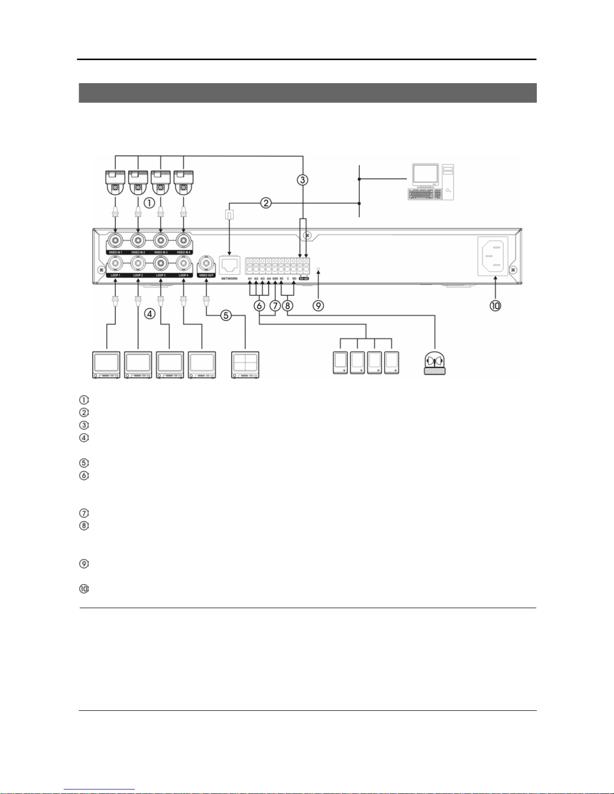
REAR PANEL CONNECTORS
No special tools are required to install the DVR. Refer to the installation manuals for the other items that
make up part of your system. Your DVR should be completely installed before proceeding.
Video In: Connect the coaxial cables from the video sources.
Network: Connect a Cat5 cable with an RJ-45 jack.
RS-485 Port: Connect a PTZ camera. Refer to Appendix – Connector Pin Outs for details.
Loop: Connect the video source to another video-out device through loop BNC connectors if
necessary.
Video Out: Connect the SPOT monitor.
Alarm In: Connect alarm-in devices. The threshold voltage for NC (Normally Closed ) is above
4.3Vand for NO (Normally Open) is below 0.3V, and it should be stable at least 0.5 seconds to be
detected.
GND: Connect the ground side of the alarm input to the GND connector.
Alarm Out: Connect an alarm-out device to NC (Normally Closed) and C (Common) connectors or
NO (Normally Open ) and C (Common) connectors. Permitted current is up to 0.5 A for 125 VAC, 1
A for 30 VDC.
Factory Reset Switch: Use this switch on rare occasions that you want to return all the settings to the
original factory settings. Refer to the Factory Reset section for details.
Power Cord: Connect the power cord to the DVR and then to the wall outlet.
NOTES:
Ÿ The Loop BNC connectors are auto terminated. Do NOT connect a cable to the Loop BNC unless it is
connected to another terminated device because it will cause poor quality video.
Ÿ To make connections on the Alarm Connector Strip, press and hold the button and insert the wire in
the hole below the button. After releasing the button, tug gently on the wire to make certain it is
connected. To disconnect a wire, press and hold the button above the wire and pull out the wire.
Ÿ This Network Port is not connected with cables or wires intended to connect to the outdoor directly.
Four-Channel Digital Video Recorder
3
FACTORY RESET
To reset the unit, you will need a straightened paperclip:
1. Turn the DVR off.
2. Turn it on again.
3. While the DVR is initializing, poke the straightened paperclip in the unlabeled hole to the right of
the RS-485 connector.
4. Hold the switch until the LEDs on the Front Panel flashes three times and are lit.
5. Release the reset switch. All of the DVR’s settings are now at the original settings it had when it
left the factory.
NOTE: When using the Factory Reset, you will lose any setting you have made. If you want to use the
same DVR name registered on the DVRNS server after initializing the system using the factory reset, you
need to contact the DVRNS server manager.
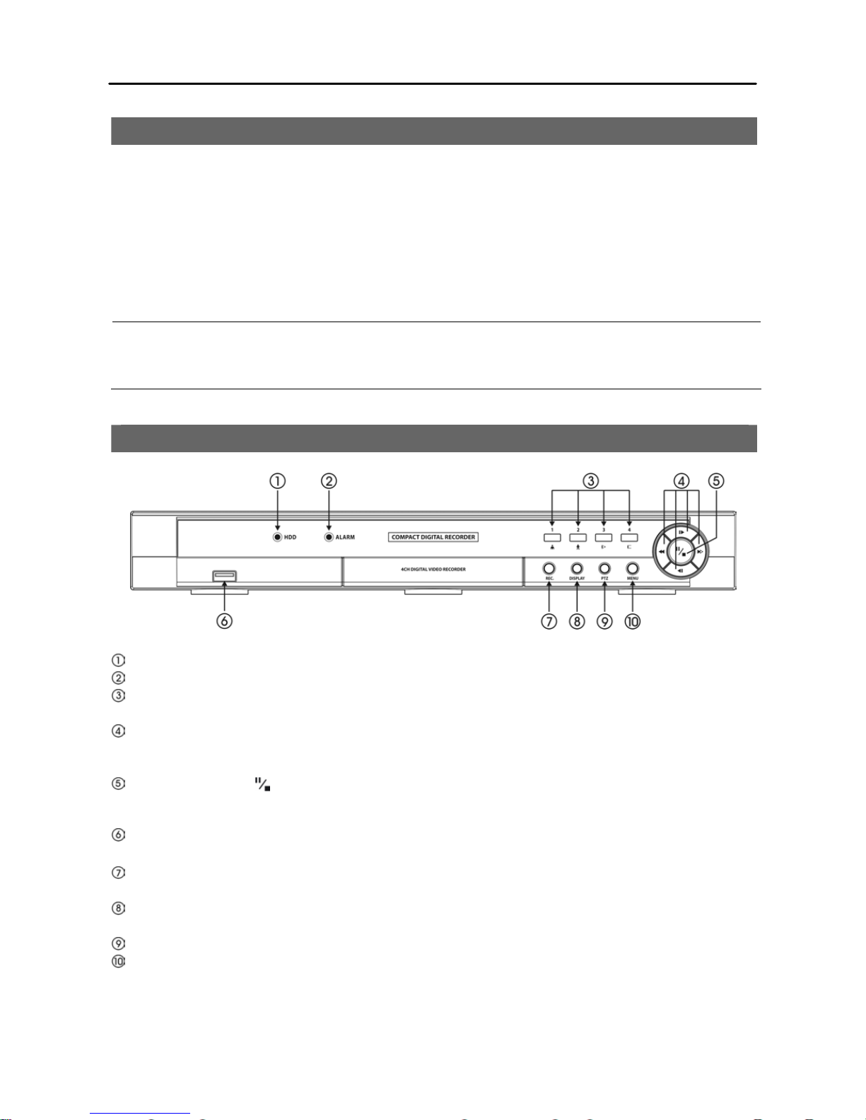
FRONT PANEL CONTROLS
HDD LED: The LED flickers when the DVR is recording or searching video on the hard disk drive.
ALARM LED: The LED is li t when alarm output or internal buzzer is activated.
Camera Buttons (1-4): Pressing the button displays the selected camera in full screen. In PTZ mode,
pressing the 1 or 2 button zooms in or out, and the 3 or 4 button focuses near or far.
Playback/Arrow Buttons: Pressing the button controls playback of recorded video in playback or
searching mode. Pressing the button moves to another item or changes a selected number value in
Main Setup menu. Pressing the button pans or tilts a PTZ camera in PTZ mode.
Pause/Stop Button ( ): Pressing the button pauses or stops playing video in playback or searching
mode. Pressing the button selects an item or completes the entry you have made in Main Setup menu.
Pressing the button freezes or releases the current screen in live-viewing mode.
USB Port: Connecting the USB flash drive allows you to upgrade the software and to import or export
DVR settings.
REC Button: Pressing the button toggles manual recording On and Off. The DVR continues
recording independently of the recording schedule while manual recording in On.
MENU Button: Pressing the button launches or closes the Main Setup menu in live-viewing or
recording mode, Search Menu in playback or searching mode, or PTZ menu in PTZ mode.
PTZ Button: Pressing the button enters or exits PTZ mode.
DISPLAY Button: Pressing the button toggles screen mode between quad and sequence.
 Loading...