

PACOM PDR16-RMT User Manual

Digital Video Recorder
i
WARNING
RISK OF ELECTRIC SHOCK
DO NOT OPEN
WARNING: TO REDUCE THE RISK OF ELECTRIC SHOCK,
DO NOT REMOVE COVER (OR BACK).
NO USER-SERVICEABLE PARTS INSIDE.
REFER SERVICING TO QUALIFIED
SERVICE PERSONNEL.
The lightning flash with arrowhead symbol, within an equilateral triangle, is intended to alert
the user to the presence of uninsulated "dangerous voltage" within the product's enclosure
that may be of sufficient magnitude to constitute a risk of electric shock.
The exclamation point within an equilateral triangle is intended to alert the user to the
presence of important operating and maintenance (servicing) instructions in the literature
accompanying the appliance.
COMPLIANCE NOTICE OF FCC:
THIS EQUIPMENT HAS BEEN TESTED AND FOUND TO COMPLY WITH THE LIMITS FOR A CLASS A DIGITAL
DEVICE, PURSUANT TO PART 15 OF THE FCC RULES. THESE LIMITS ARE DESIGNED TO PROVIDE
REASONABLE PROTECTION AGAINST HARMFUL INTERFERENCE WHEN THE EQUIPMENT IS OPERATED
IN A COMMERCIAL ENVIRONMENT. THIS EQUIPMENT GENERATES, USES, AND CAN RADIATE RADIO
FREQUENCY ENERGY AND IF NOT INSTALLED AND USED IN ACC ORDANCE WITH THE INSTRUCTION
MANUAL, MAY CAUSE HARMFUL INTERFERENCE TO RADIO COMMUNICATIONS. OPERATION OF THIS
EQUIPMENT IN A RESIDENTIAL AREA IS LIKELY TO CAUSE HARMFUL INTERFERENCE, IN WHICH CASE
USERS WILL BE REQUIRED TO CORRECT THE INTERFERENCE AT THEIR OWN EXPENSE.
WARNING: CHANGES OR MODIFICATIONS NOT EXPRESSLY APPROVED BY THE PARTY RESPONSIBLE
FOR COMPLIANCE COULD VOID THE USER’S AUTHORITY TO OPERATE THE EQUIPMENT.
THIS CLASS OF DIGITAL APPARATUS MEETS ALL REQUIREMENTS OF THE CANADIAN
INTERFERENCE-CAUSING EQUIPMENT REGULATIONS.
The information in this manual is believed to be accurate as of the date of publication. Pacific Communications is not
responsible for any problems resulting from the use thereof. The information contained herein is subject to change
without notice. Revisions or new editions to this publication may be issued to incorporate such changes.
User’s Manual
ii
Important Safeguards
1. Read Instructions
All the safety and operating instructions should be read before the
appliance is operated.
2. Keep Instructions
The safety and operating instructions should be kept for future
reference.
3. Cleaning
Unplug this equipment from the wall outlet before cl ean ing it. Do not
use liquid aerosol cleaners. Use a damp soft cloth for cleaning.
4. Attachments
Never add any attachments and/or equipment with out the approval of
the manufacturer as such additions may result in the risk of fire, e lectric
shock or other personal injury.
5. Water and/or Moisture
Do not use this equipment near w a ter or in contact with water.
6. Accessories
Do not place this equipment on an unstable cart , stand or table. The
equipment may fall, causing serious injury to a child or adult, and
serious damage to the equipment. Wall or shelf mounting should
follow the manufacturer's instructions, and should use a mounting kit
approved by the manufacturer.
This equipment and cart combination should be moved with care.
Quick stops, excessive force, and uneven surfaces may cause the
equipment and cart combination to overturn.
7. Ventilation
Slots and openings in the cabinet and th e back or bo ttom are provid ed
for ventilation, and to ensure reliable ope ration of the equipm ent and to
protect it from overheating. These openings must not be blocked or
covered. Do not block these openings or allow them to be blocked by
placing the equipment on a bed, sofa, rug, or bookcase. En sure that
there is adequate ventilation and that the manufacturer’s instructions
have been adhered to.
8. Power Sources
This equipment should be operated only from the type of power source
indicated on the marking label. If you are not sure of the type of power,
please consult your equipment dealer or local power company.
9. Power Cords
Operator or installer must remove power and other connections before
handling the equipment.
10. Lightning
For added protection for this equipment during a ligh tning storm, or
when it is left unattended and unused for l ong periods of tim e, unplug it
from the wall outlet and disconnect the antenna or cable system. This
will prevent damage to the equipment due to light ning and power-lin e
surges.
11. Overloading
Do not overload wall outlets and extension co rds as this can result in
the risk of fire or electric shock.
12. Objects and Liquids
Never push objects of any kind through openings of this equipment as
they may touch dangerous volt age points or sho rt out parts th at could
result in a fire or electric shock. Never spill liquid of any kind on the
equipment.
13. Servicing
Do not attempt to service this equipment you rself. Refer all serv icing
to qualified service personnel.
14. Damage requiring Service
Unplug this equipment from the wall outlet and refer servicing to
qualified service personnel under the following conditions:
A. When the power-supply cord or the plug has been damaged.
B. If liquid is spilled, or objects have fallen into the equipment.
C. If the equipment has been exposed to rain or water.
D. If the equipment does not operate normally by following the
operating instructions, adjust only those controls that are cove red by
the operating instructions as an improper adjustment of other
controls may result in damage and will often require extensive work
by a qualified technician to restore the equipment to its normal
operation.
E. If the equipment has been dropped, or the cabinet damaged.
F. When the equipment exhibits a distinct change in perfo rmance —
this indicates a need for service.
15. Replacement Parts
When replacement parts are required, be sure the service te chnician has
used replacement parts specified by the manufacturer or that have the
same characteristics as the original p art. Unauthorized substitutions
may result in fire, electric shock or other hazards.
16. Safety Check
Upon completion of any service or repairs to this equi pment, ask the
service technician to perform safety checks to determine that the
equipment is in proper operating condition.
17. Field Installation
This installation should be made by a qu alified service person and
should conform to all local codes.
18. Telnet Communication Cable
Caution: To reduce the risk of fire, use only No. 26 AWG or larger
telecommunication line cord.
19. Danger of explosion if battery is incorrectly replaced. Replace
only with same or equivalent type recommended by manufacturer.
Discard used batteries according to the manufacturer’s instruction.

Digital Video Recorder
iii
Table of Contents
Chapter 1 — Product Information......................................................................................1
Features.........................................................................................................................1
System Types................................................................................................................1
System Diagram............................................................................................................1
Front Panel....................................................................................................................2
Rear Panel.....................................................................................................................2
Turning On the DVR......................................................................................................3
Turning Off the DVR......................................................................................................3
Chapter 2 — Tools.............................................................................................................5
SmartGuard...................................................................................................................5
Overview ...................................................................................................................5
Features....................................................................................................................5
Main GUI...................................................................................................................5
SmartGuard Setup..................................................................................................10
SmartSearch................................................................................................................36
Overview .................................................................................................................36
Features..................................................................................................................36
Main GUI.................................................................................................................36
SmartSearch Environment Setup............................................................................51
SmartBackup...............................................................................................................53
SmartPager..................................................................................................................58
Chapter 3 — Remote Access ..........................................................................................59
Installation....................................................................................................................59
POST System Setup ...................................................................................................59
BASE System Setup....................................................................................................60
SmartBase — Remote Monitoring and Recording Software ..................................60
SmartSearch — Remote and Local Playback Software .........................................67
Appendix 1 — Accessing Windows.................................................................................69
Appendix 2 — SmartShell................................................................................................70
Appendix 3 — Network Setup (LAN)...............................................................................72
Appendix 4 — Network Setup (Modem)..........................................................................75
Appendix 5 — WebGuard..............................................................................................104
Appendix 6 — Time Synchronization.............................................................................108
Appendix 7 — Text-In Query.........................................................................................110
Appendix 8 — RAS Mobile ............................................................................................112
Appendix 9 — Protocol for Remote Controlling DVR....................................................117
Appendix 10 — Troubleshooting ...................................................................................121
Appendix 11 — Specifications.......................................................................................122

User’s Manual
iv
Digital Video Recorder
1
Chapter 1 — Product Information
Features
y Compatible with color cameras and other standard video sources
y Compatible with network cameras (PDR32-HYB model only)
y Video synchronization not required
y Pentaplex operation for simultaneous recording, multi-screen viewing, playback, remote monitoring and
archiving
y Versatile display formats for convenient user interface; single-screen, full-screen, quad, 3x3, 4x4, 5x5, 3+4, 2+8
and 1+32
y Main and Spot monitor outputs
y On-screen graphic display including camera title, location, recording status and mode display
y Sequence mode available in all screen formats
y Hardware watchdog timer function
y Programmable motion detection for each camera input using graphic user interface
y Various image enhancement functions including zoom in/out, brightness, interpolation, blur and sharpness
y Remote monitoring, playback and control through LAN, PSTN and ISDN
y User-friendly interface
y Proprietary encryption scheme preventing video from alteration
y Max. 32-channel alarm input and 32-channel alarm output (Not included in all models)
NOTE: This manual covers the 16- and 32channel digital video recorders For simplicity, the illustrations and
descriptions in this manual refer to the 32-channel model. See Appendix 11 – Specifications for the system
specifications of each model.
System Types
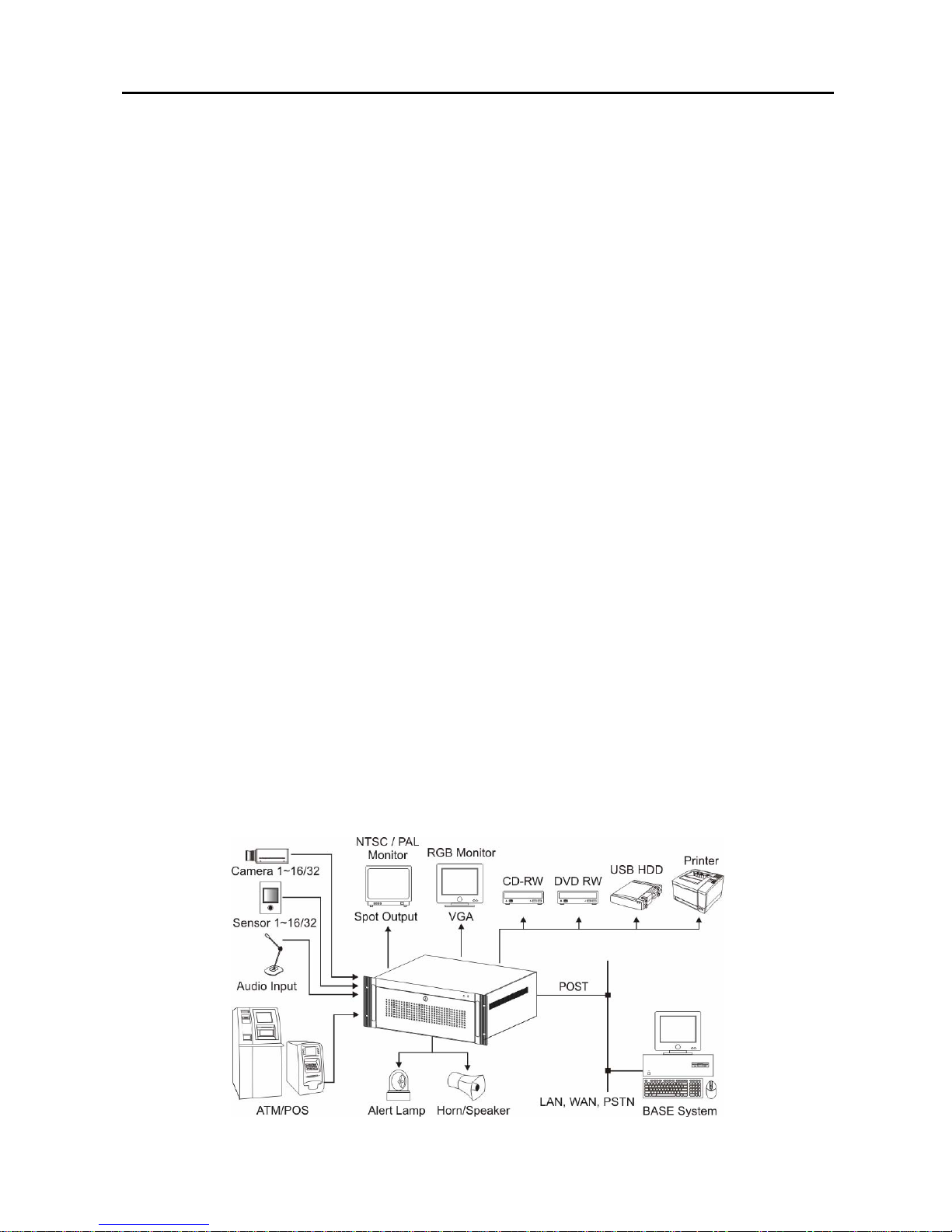
There are two system types: POST DVR system and BASE system. The POST is a complete DVR system with
cameras, and the BASE is a computer with software to access the POST DVR. The BASE can view live or
previously recorded video from the POST DVR. The POST DVR can access another POST DVR when they are
networked via LAN, however, it can only review previously recorded video and cannot view live video from the
other POST DVR.
System Diagram
User’s Manual
2
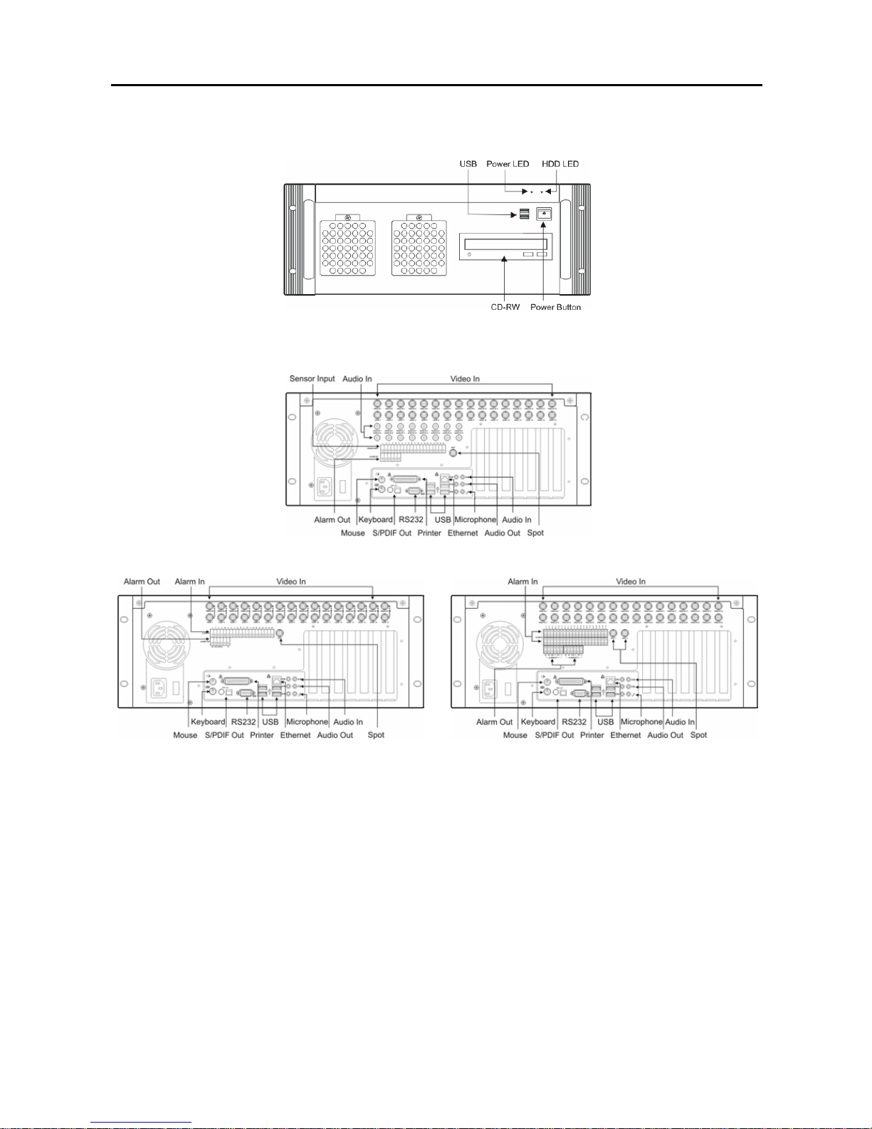
Front Panel
Rear Panel
PDR16-RMT-RT model
PDR16-RMT series and PDR32-HYB models PDR32-RMT and PDR32-RMT-X models
NOTE: Windows may not operate properly when using the USB connectors on the front panel of the DVR,
depending on the model type of the USB device. In this case, connect the USB device after Windows boots
properly or use the USB connectors located on the rear panel.

Digital Video Recorder
3
Turning On the DVR
Press the power button located on the front p anel to turn the system on. The system goes into the SmartGuard mode
as soon as it finishes its boot process.
CAUTION: The system will lock up if the monitor does not have high enough resolution. The DVR
requires 1024x768 resolution.
Turning Off the DVR
Click the POWER button in the SmartGuard mode or press the power button on the front panel to turn the system
off.
NOTE: When turning off the system, you m ust conf irm t hat y ou want to turn off the unit. You will also be asked
for a user ID and password, or system quit procedure if the Shut Down option was selected for the user’s
authorization during the SmartGuard setup.
CAUTION: The system can be shut down by force by pressing the power button on the front panel over
10 seconds. However, follow the normal shutdown procedures as mentioned above when the system is
operating normally. Turning off the DVR without shutdown procedures can cause damage to the
system.

User’s Manual
4
Digital Video Recorder
5
Chapter 2 — Tools
SmartGuard
Overview
SmartGuard is powerful surveillance software. It provides multiplexer functions, digital time-lapse recording and
event-driven recording. SmartGuard also provides motion detection, PTZ control and various image enhancement
functions.
NOTE: The first time you turn on the system, it will immediately begin recording. If you have less than 32
cameras, you must enter the setup screen and deactivate any inputs to which cameras are not connected;
otherwise, the recording speed might be decreased somewhat.
Features
y Max. 32 channels
y Max. 480 images/sec recording (400 images/sec PAL) (PDR16-RMT-RT model)
y User-friendly interface
y Scheduling by camera and time
y Time-lapse or event-driven recording
y Motion detection and object tracker function
y Audio recording
y PTZ control
NOTE: See Appendix 11 – Specifications for the max imum recordin g speed of each model.
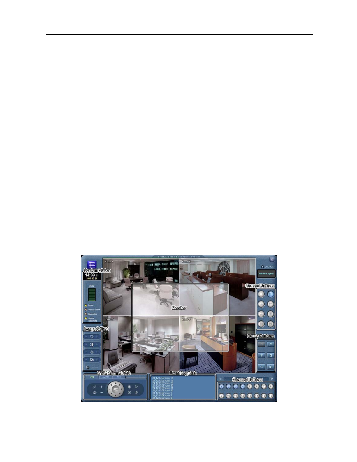
Main GUI
User’s Manual
6
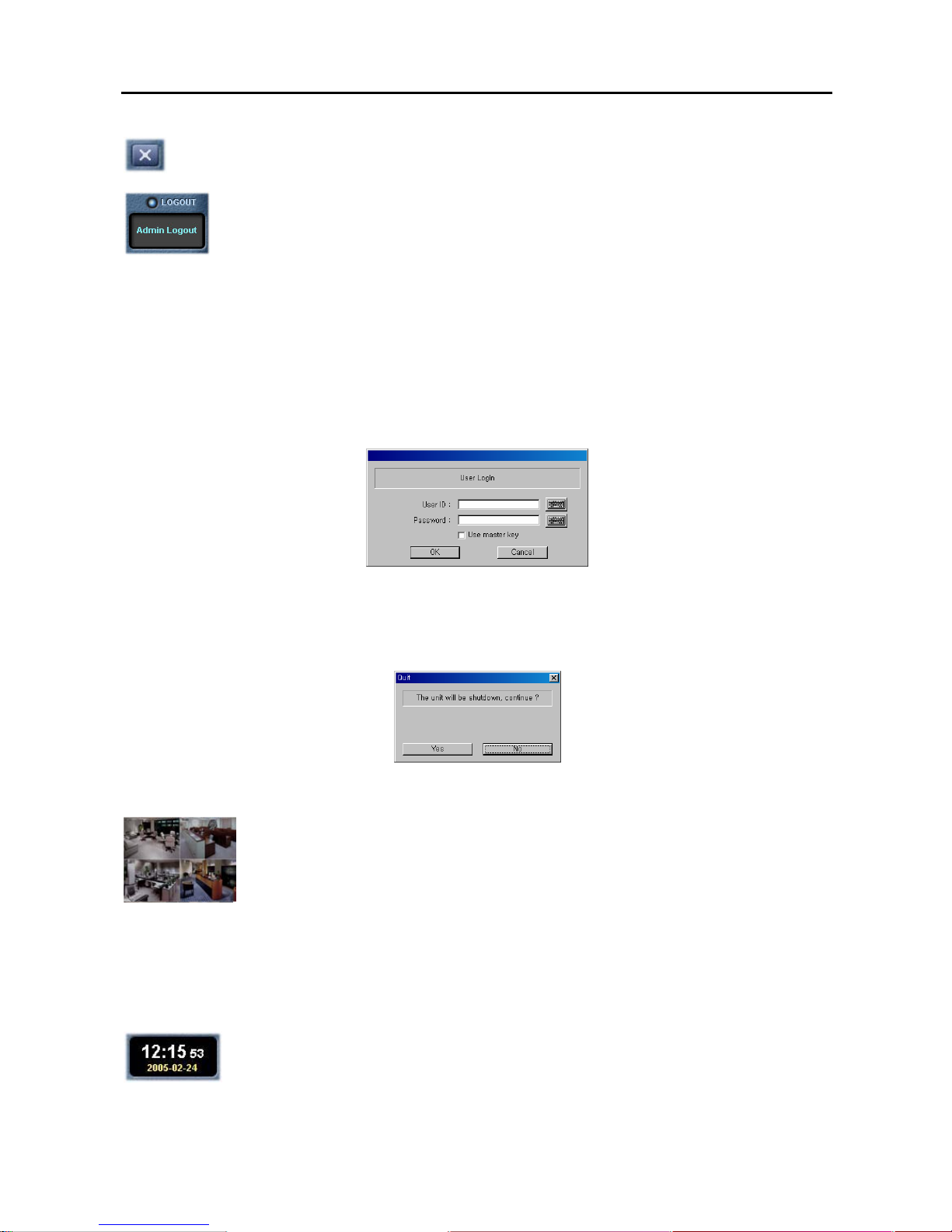
Quit: Click the button to quit the system.
Login / Logout: Click the button to log in or log out the system.
Logging In/Out the System
Click the Logout button after logging out, the following User Login dialog box appears. Enter the User ID and
Password and then click the OK button if you want to log in the system. If th e login fails m ore than three times, the
buzzer will be activated for three minutes. The successful login can stop the buzzer trigger during the buzzer
activation. The log for failed login as well as successful login will be displayed on the system status window.
NOTE: When No local login is selected during the SmartGuard – Authority setup, the DVR does not ask login
procedure.
NOTE: When you forgot the password, ask your dealer or distributor.
Click the Login button after logging in, the following Quit dialog box appears. Click the Yes button if you want to
log out the system.
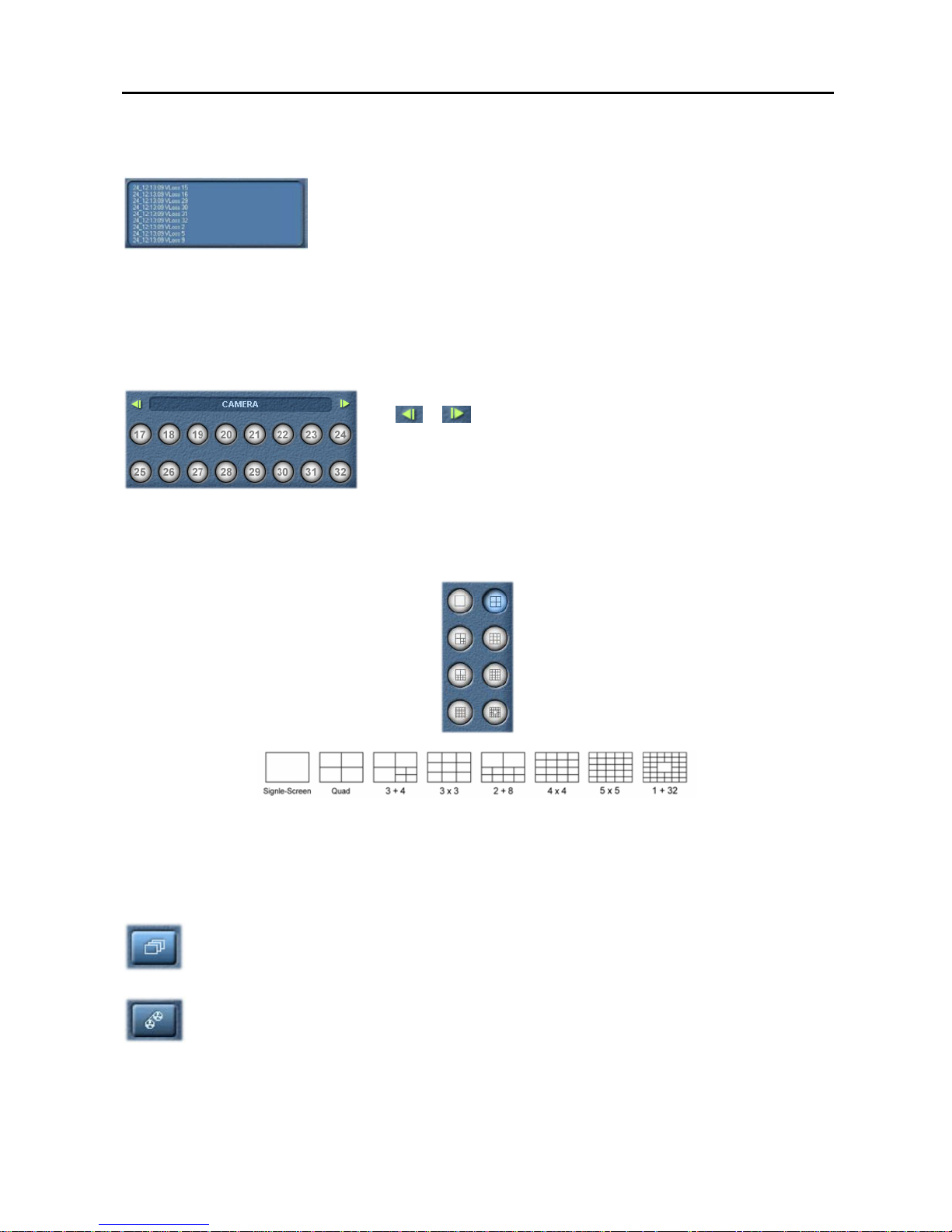
Monitor
Display Format: Various display formats (single-screen, full-screen, quad, 3+4, 3x3, 2+8, 4x4,
5x5 and 1+32) are provided for convenient user interface. Each format can be selected by
clicking the screen buttons shown below. The camera groups for multi-screen formats are
composed of cameras 1 to 32 in order. The user can select which camera group is displayed by
clicking any camera button in a group from camera buttons shown below.
OSD: Information including camera title, recording mode, and recording status can be displayed on the image. Go
to Setting Up the System and Setting Up Cameras in the SmartGuard Setup section, and place a check in the Show
OSD box to display the OSD information.
System Status
Clock Mode: Click the left mouse button on the clock area to set date display
(MM-DD-YYYY/...) and time display (12 Hours/24 Hours) formats. Click the right mouse button
on the clock area to set date, time and time zone.
CAUTION: If you change the time, images dated later than the new date/time are deleted. Back up the
images if you want to save them.
Digital Video Recorder
7
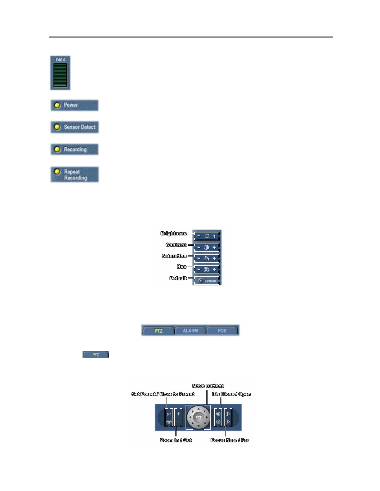
HDD Indicator: Shows the remaining hard disk space.
Power LED: The Power LED is lit when the DVR is On.
Alarm LED: The Sensor Detect LED is lit when the sensor has been detected.
Mode Status: The Recording LED is lit when the DVR is in the recording mode.
HDD Usage: The Repeat Recording LED is lit when the DVR is set to repeat recording in
case of recording space shortage.
Image Adjust
You can adjust the brightness, contrast, hue and saturation by clicking the designated buttons. Click the Default
button to reset them to the default settings.
NOTE: These adjustments should not be used to correct improperly set cameras or monitors.
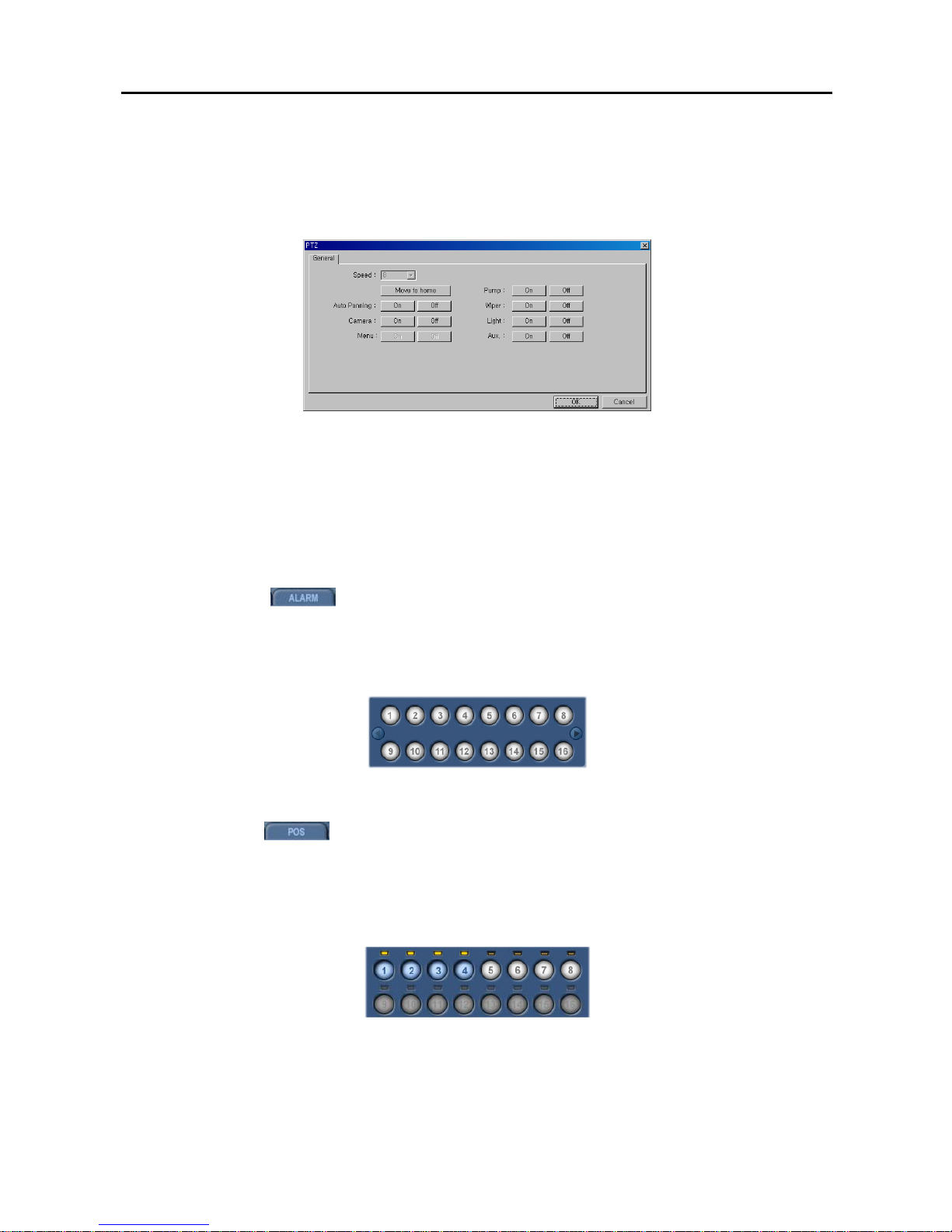
PTZ Control
The DVR provides transmission functions, and you can control popular PTZ devices and dome cameras. Clicking
the PTZ icon
button displays the PTZ control buttons as shown below. You can also use the mouse to
control PTZ functions. Click the right mouse button on the image and move that that image to the direction you want
by dragging the mouse. Roll the mouse wheel to zoom in or out.
User’s Manual
8
NOTE: Up to 128 presets can be set, depending on the specification of installed PTZ devices or dome cameras.
Make sure available preset numbers first to make the PTZ preset function work properly.
NOTE: If you want to set up the advanced PTZ control, place the cursor on the PTZ control panel, and click the
right mouse button. Depending on the camera specifications, some features may not be supported.
y Speed: Set the pan/tilt speed (from 1 to 16). The higher the number, the faster it moves.
y Move to origin: Click the button if you want to move the camera to the origin position.
y Auto Panning: Enables or disables auto panning.
y Camera: Turns on or turns off the camera.
y Menu: Enables or disables the menu function.
y Pump / Wiper / Light / Aux: Enables or disables pump, wiper, light and other available functions.
Alarm Control
Clicking the alarm icon
button causes the alarm control buttons to display as shown below. The user can
check the alarm status and control the alarm output. Pressed alarm button is active mode, and released button is
inactive mode. The user can active or inactive alarm output manually by clicking the button when it is released or
pressed. If the user disables the a larm during the Alarm setup on the SmartGuard, the al arm button will be disabled.
Click the left or right arrow buttons to display the previous or next alarm button panel.
POS
Clicking the POS icon
button causes the POS control buttons to display as shown below. The system
status window will display the POS data. Click the right mouse button on the window to toggle two display modes:
POS data display mode, and event log including POS data display mode. The POS button LED will be lit while the
data is coming from the POS. If you do not want to display the data from the POS, release the target POS number
button. If the user disables the POS device during the Text-In setup on the SmartGuard, the POS button will be
disabled.
Digital Video Recorder
9
Event Logging
To scroll up and down the list, hold down the left mouse button on the list and move
the cursor up and down, or roll the mouse wheel on the list.
NOTE: Event log list displays the conditions of hard disk drives w hen the inst alle d IDE h ard disk drives support
S.M.A.R.T. (Self-Monitoring, Analysis and Reporting Technology) Monitoring program. If the DVR senses that
the status of the hard disk drives is Poor, the error messages box screen will appear. Once the error message
box displays, replacing the hard disk drive as soon as possible is recommended, usually within 24 hours.
Camera Buttons
Click the individual camera buttons to display the selected camera. Click
the
or button to display the previous or next camera button panel.
Screen Buttons
To select the desired screen mode, click of the buttons shown below.
y To view a specific image in the single-screen mode, move the cursor to that image and double click the left mouse
button.
y To return to the previous screen mode from the single-screen mode, click the left mouse button in the window.
Utility Buttons
Auto Sequencing: When the Sequence button is clicked, the SmartGuard sequences the cameras in
order. Whenever you click the button, it toggles between On and Off. The s witching interv al can b e set
during the system setup.
Mode Selection: The record mode is selected when th e Record button is click ed. SmartGuard returns
to view only mode automatically when it is unable to record (for example, when the hard disk is full).
NOTE: The DVR records only in accordance with the recording schedule, which can be set during the system
setup. Before you install the DVR, you need to fully understand the recording schedule. Note also that clicking
the Record button only prepares the DVR for recording. In this state, the DVR will follow the recording schedule.
User’s Manual
10
Manual Alarm Output: In general, the alarm is activated automatically when any related sensor is
activated. However, the user can activate all the alarm output m anually b y clicking the button while it is
released or deactivate all the alarm output by clicking the button when it is pressed.
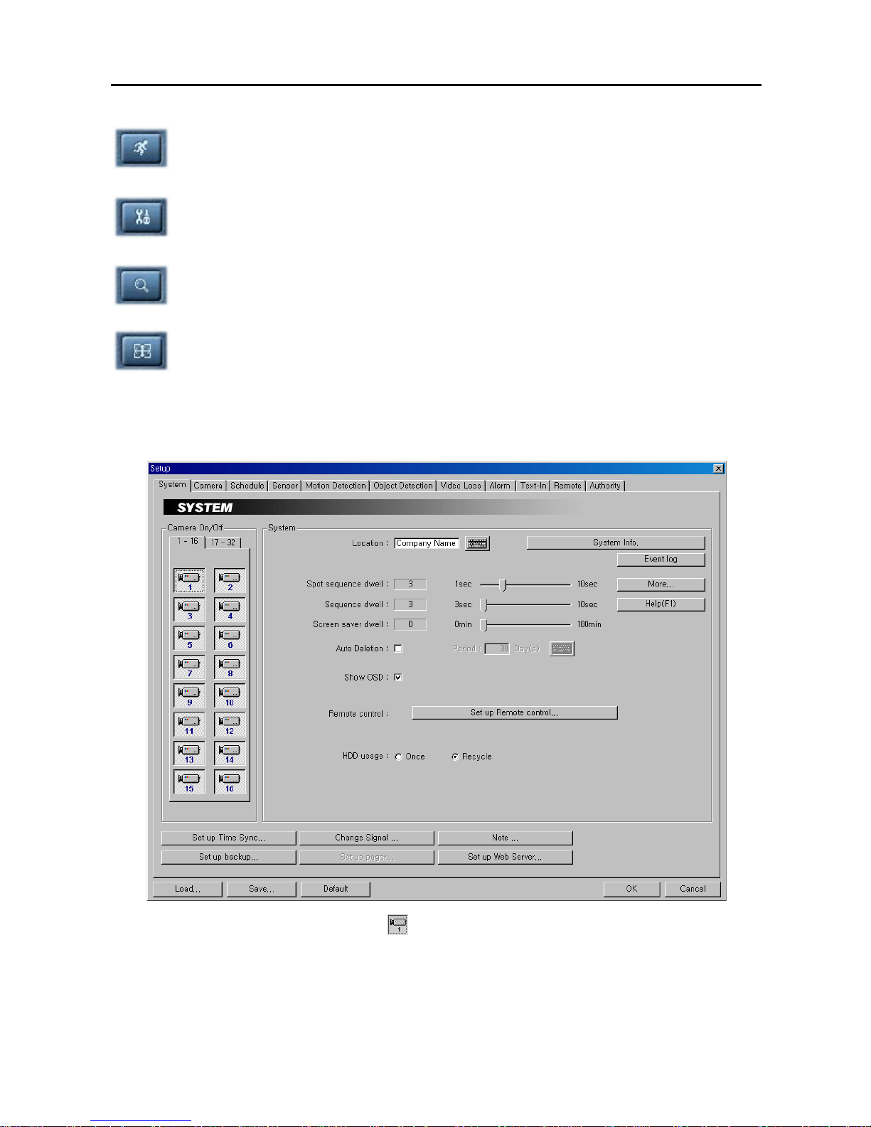
Setup: When the Setup button is clicked, a dialog box appears. The dialog box has nine tabs. See the
following SmartGuard Setup section.
Accessing SmartSearch: Click the Search button to run the SmartSearch.
Full Screen: Click this button to enter the full-screen mode. All of the control buttons disappear, and
the monitoring window takes up the full screen in the full-screen display mode. To return from the
full-screen mode, click the left mouse button anywhere on the screen.
SmartGuard Setup
Setting Up the System
1. Click the Camera icon to enable the camera.
NOTE: Selecting 1-16 tab displays camera channels 1 to 16 and selecting 17-32 tab displays 17 to 32.
2. Click the text field beside Location. If you have a keyboard attached to your unit, enter a location name such as
"Main Office". If you do not have a keyboard connected to the unit, clicking the keyboard icon will display a
virtual keyboard on which you can type by clicking the letters.

Digital Video Recorder
11
3. Click the System Info… button, and the System Info. dialog box appears. The dialog box displays the
information of the installed cards, driver, software, hard disk drive, and OS on the system.
4. Click the Event log button to display the event log list of the system.
5. Click the Help (F1) button to display the ele ctron ic file of user’s manual. The Help function also can b e enabled
by hitting the F1 key on the keyboard.
6. Move to Spot sequence dwell, and set the sequence dwell time for the Spot monitor by holding down and
dragging the pointer. If you set the value to 3 seconds, the camera display will sequence every three seconds on
the Spot monitor.
7. Click the More… button, and set up the spot sequence in detail.
8. Move to Spot, and click the Spot monitor icon to connect. No (0), one, four or eight monitors can be connected
according to the DVR specification.
9. Move to Spot Sequence, and select the camera n umber for each number (32-chann el DVR: Camera 1 to 16 for
Spot 1 to 4 and Camera 17 to 32 for Spot 5 to 8, 16-channel DVR: Camera 1 to 16 for Spot 1 to 8) to
sequence or Not Used from a drop-down list.
10. Move to Hold spot during single-screen mode, and check the box if you do not want the cameras sequence on
the Spot monitor while the main monitor is set to the single-screen display mode.
11. Move to Include event display, and check the box and select the type of event you want to display during spot
sequence. Multiple events can be selected.
NOTE: Event display will be enabled when y ou set up the event monitoring during the Cam era advanced setup.
Refer to the Setting Up Cameras section for details.
12. Move to Show video loss, and check the box if you want to show the video loss image during spot sequence.
13. Move to Monitoring without login, and check the box if you want to view video on the Spot monitor without
login.
User’s Manual
12
14. Move to Sequence dwell, and set the sequence dwell time for the main monitor by holding down and dragging
the pointer. If you set the value to 3 seconds for the Sequence dwell, the camera d isplay will sequence every three
seconds on the Main monitor.
15. Move to Screen saver dwell, and set the screen s aver dwell t ime for th e displa y image. The scr een s aver will be
activated if there is no keyboard or mouse operation during the preset dwell time.
16. Move to Auto Deletion, and check the box if you want to delete the video recorded earlier than user-defined
period. When checking the Auto deletion box, move to Period and set the period to keep the record ed video. e.g.
If you check the Auto deletion box, and set 30 days in the Period box, the DVR will automatically delete the
video which is older than 30 days from the current day.
17. Move to Show OSD, and check the box if you want to d isplay OSD inform ation on the imag e. OS D information
includes camera title, recording mode and recording status and event detection status.
NOTE: A R indicates the target camera is in the Time-lapse recording schedule mode. An E indicates it is in the
Event-driven recording mode. A R/E indicates it is in the Time & Event recording mode. A R located at the
bottom-right corner indicates the DVR is recording video, and the blink rate of the R relates to the recording
speed. A
■ icon displaying at the bottom-left corner indicates that motion detection or object detection events
occur.
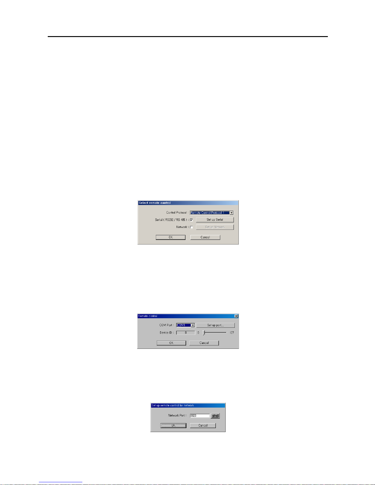
18. Move to Remote control, and click the Set up Remote control... button when the DVR is controlled remotely
using the serial communication signals or via network connections.
19. Move to Control Protocol, and select the protocol from the drop-down list that the connected remote control
device supports.
20. Move to Serial (RS232 / RS485), and check the box and click the Set up Serial when the DVR is controlled
remotely using the serial communication signals. Select the DVR's COM port to use from the drop-down list.
Click the Set up port... button, and set the Baud rate from 300 to 256,000. Select Parity from None, Even or
Odd parity. Select Data bit from 7 bit or 8 bit format. Select Stop bit from 1 bit or 2 bits from the drop-down
list. Move to Device ID, and set the device ID number from 0 to 127 using the slide bar. See Appendix 9 –
Protocol for Remote Controlling DVR for details.
NOTE: When using the RS485 port on the extension card, select the given COM Port number. To check the
given COM port number, please refer to the installed card information displayed on the System Info. dialog box
by clicking the System Info. button.
21. Move to Network, and check the box and click the Set up Network when the DVR is controlled remotely via
network connections. Enter the Network Port number.
Digital Video Recorder
13
NOTE: When selecting the Network remote control for the user’s authorization, you can control the DVR
remotely via network connections. Refer to the Setting Up the Authority section for details.
22. Move to HDD usage, and select either Once or Recycle. When Once is selected, the DVR stops recording
when the hard disk drive is full. When Recycle is selected, the DVR continues recording when the hard disk
drive is full by overwriting the oldest video.
23. Click the Set up Time Sync… button, and set up the time synchronization if required. See Appendix 6 – Time
Synchronization for details.
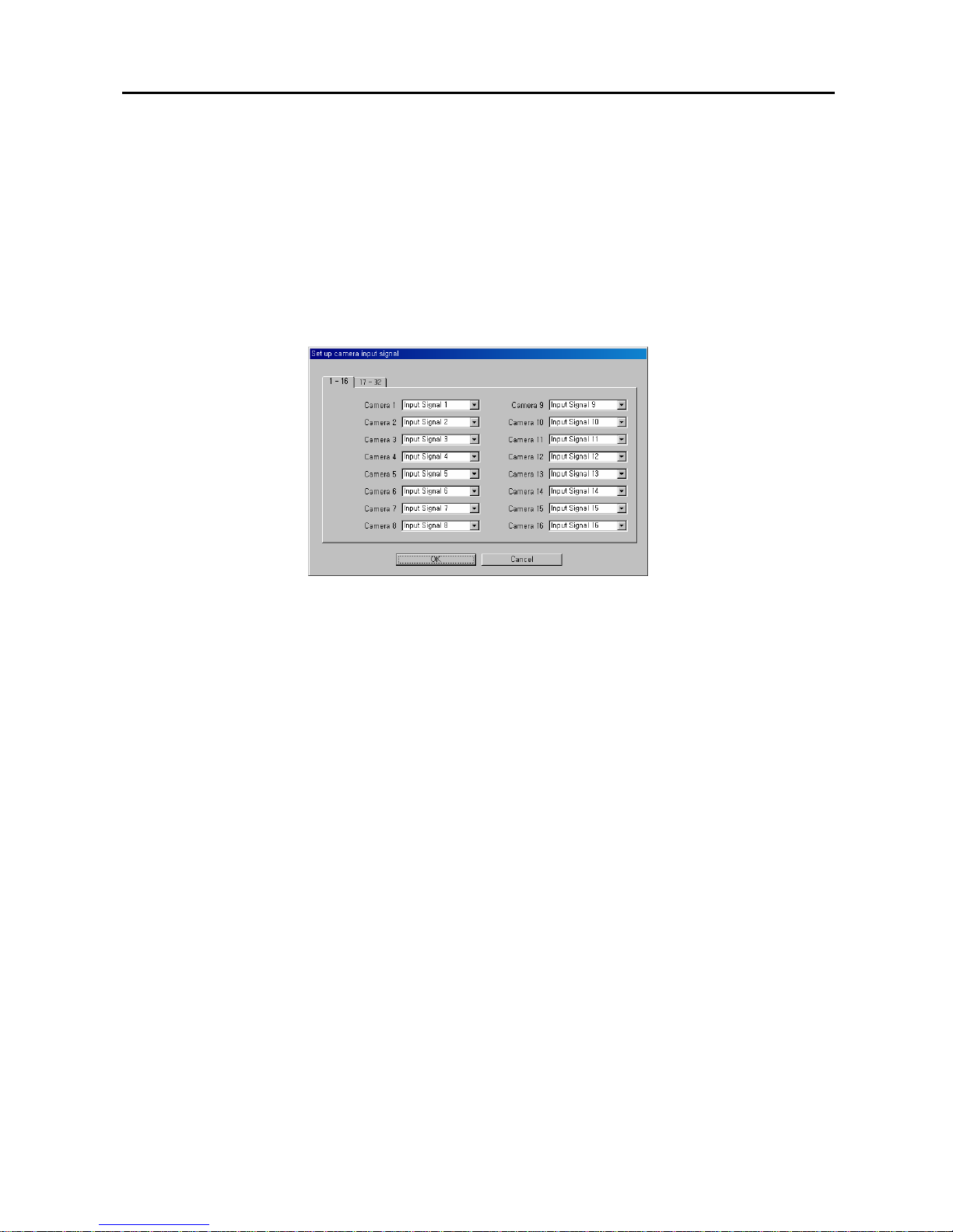
24. Click the Change Signal… button, and select the video input signal to each camera number (Camera 1 to
Camera 32) from a drop-down list (Input Signal 1 to Input Signal 16 for the camera numbers 1 to 16, and Input
Signal 17 to Input Signal 32 for the camera numbers 17 to 32).
25. Click the Note… button, and set up the note function. The user can add or delete notes. If you want to read the
note, select the line and click the View button. Click the Load button to load the saved note, the Save button to
save the current note, and the Text Save button to save the current note to the text file.
26. Click the Set up backup... button, and set up backup information. See the SmartBackup section.
27. Click the Set up pager... button, and set up pager information. See the SmartPager section.
NOTE: The Set up pager... button will be activated if you set up SmartPager to start in the SmartGuard setup.
28. Click the Set up Web Server... button, and set up an IIS (Internet Information Services) for the WebGuard
program.
29. Click the Load... button if you want to load typical settings. Click the Save... button if you want to save settings.
Click the Default button if you want to load default settings. You can save your changes by clicking the OK
button. Selecting Cancel exits the dialog box without saving the changes.
NOTE: Only the administrator level user can use the Load, Save and Default buttons.
User’s Manual
14
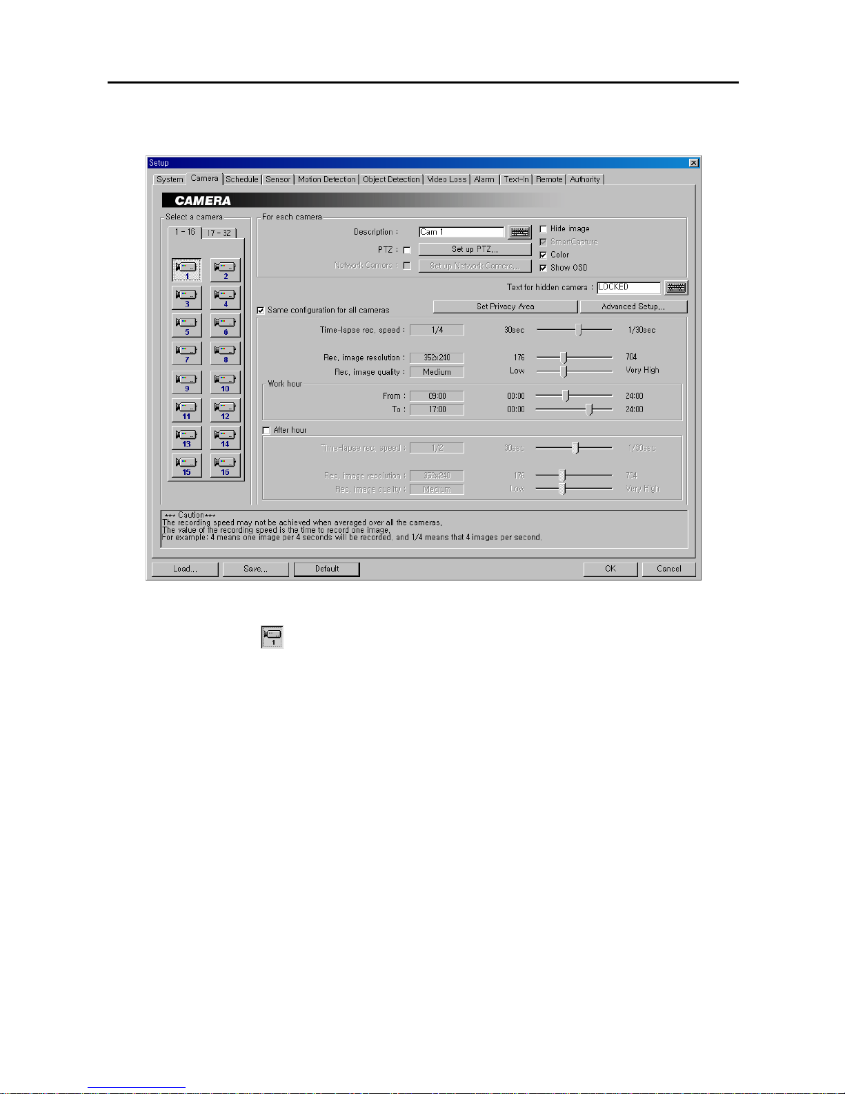
Setting Up Cameras
CAUTION: The recording speed may not be achieved when averaged over all the cameras.
1. Click the Camera icon.
NOTE: Selecting 1-16 tab displays camera channels 1 to 16 and selecting 17-32 tab displays 17 to 32. Select
17-32 tab to set up network cameras. (PDR32-HYB model only).
2. Click the text field beside Description, and enter a camera title such as "Front Door". You can use either the
actual keyboard or the virtual keyboard.
3. Move to PTZ, and check the box to enable pan, tilt and zoom functions. (Not available for network cameras)
NOTE: To control camera pan, tilt and zoom, you must attach a compatible RX device or dome camera to the
DVR. A list of supported RX devices and dome camera models can be found in the Set up PTZ dialog box.
When controlling a PTZ camera via RS485, use the RS485 port on the extension card.
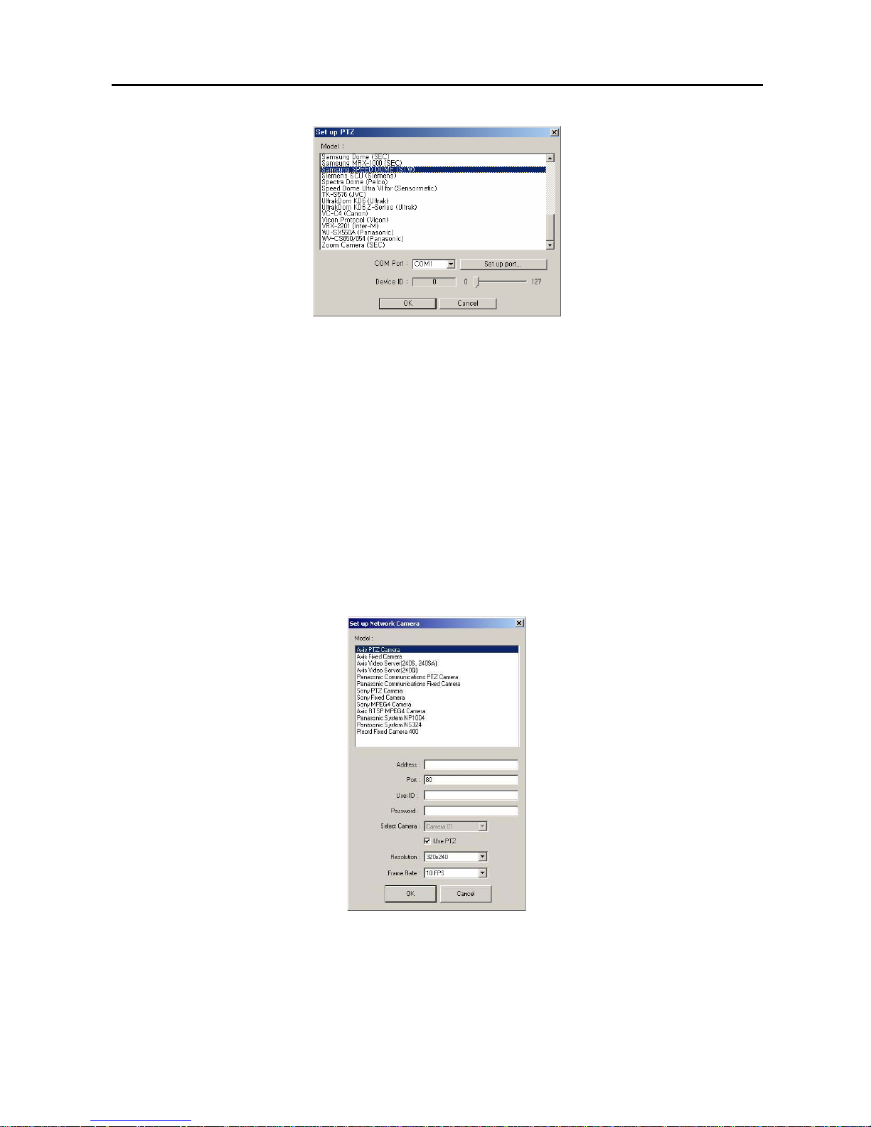
4. Click the Set up PTZ... button to display the Set up PTZ dialog box. Select the model of th e installed RX device
or dome camera from the Model list
Digital Video Recorder
15
y COM Port: Select the COM port to use from the drop-down list.
y Set up port…: Click the button to display the Set up COM port dialog box. Set the Baud rate from 300 to
256,000, select the Parity from None, Even or Odd parity, select the Data bit from 7 bit or 8 bit format, select
the Stop bit from 1 bit or 2 bits from the drop-down list.
y Device ID: Set the device ID number from 0 to 127 using the slide bar.
NOTE: When using the RS485 port on the extension card, select the given COM Port number. To check the
given COM port number, please refer to the installed card information displayed on the System Info. dialog box
by clicking the System Info. button..
5. Move to Network Camera, and check the box to use network cameras. (PDR32-HYB model only)
NOTE: When using all 16 camera channels, the recording speed might be decr eased depending on the network
conditions.
6. Click the Set up Network Camera… button to d isplay the Set up Network Camera dialog box. Select the type
(or model) of the installed network camera or video server from the Model list.
y Address / Port / User ID / Password: Enter the IP address, port number, user ID and password of the selected
model.
y Select Camera: Select the camera to display on the screen if the selected model is a network video server.
y Use PTZ: Select the box to use PTZ function if the selected network camera supports PTZ function.
y Resolution: Set the display resolution of the selected network camera.
y Frame Rate: Set the frame rate of the selected network camera.

User’s Manual
16
7. Move to Hide image, and check the box to hide the image of the selected camera on the monitor. If this box is
checked, the selected camera will not be displayed on the monitor, however, the images from the camera will be
recorded while in the record mode.
8. Click the text field beside Text for hidden camera, and enter the text to be displayed on the hidden camera using
the actual keyboard or the virtual keyboard. If you leave this box empty, the gray screen without any text will be
displayed for the hidden camera.
9. Move to SmartCapture, and check the box to use the SmartCapture technique.
NOTE: The DVR captures the images very quickly using a unique techn ique c alled Smart Capture. How ever, it
is possible that some PAL cameras will have shaky images when using this program. Do not check this box if
your cameras have shaky images.
10. Move to Color, and check the box when using a color camera. When using a B&W camera, make certain the box
is not checked. This will reduce noise, giving better recorded image quality.
NOTE: The PDR16-RMT-RT model supports 16-channel audio input. If y ou select Record Audio, recording
audio will be activated while the DVR is recording video. The Camera setup dialog box in this manua l is for the
32-channel DVR, the Record audio option has been disabled.
11. Move to Show OSD, and check the box if you w ant to show OSD informat ion on the im age of selected camera. If
you want to enable Show OSD function, the Show OSD option should be selected during the System setup.
12. Move to Same configuration for all cameras, and check the box to set all cameras with the same configuration.
13. Move to Time-lapse rec. speed, and set the recording speed for the time-lapse mode by holding down and
dragging the pointer. You can set the speed from 30 to 1/30 seconds. The value of the recording speed is th e time
to record one image. Therefore the lower the value, the more images are recorded during the same time. For
example: 30 means one image per 30 seconds will be recorded, 1 means one image per second, and 1/30 means
that 30 images per second.
NOTE: When the recording speed is set to higher than 1/2 sec. (less than two images per second), recorded
audio will NOT be played.
NOTE: The PDR16-RMT-X, PDR16-RMT-LIVE-X, PDR32-RMT and PDR32-RMT-X models have a maximu m
recording speed of 240 images per second (200 images for PAL) that will be applied globally depending on the
number of cameras recorded. However, this maximum recording speed can be decreased when using more
than eight cameras. The PDR16-RMT, PDR16-RMT-LIVE and PDR32-HYB models ha ve a maximum recording
speed of 120 images per second (100 images for PAL), and this maximum recording speed can be decreased
when using more than four cameras. See Appendix 11 – Specifications for the maximum recording speed of
each model.
14. Move to Rec. image resolution, and set the record image size recorded by holding down and dragging the
pointer.
NOTE: Higher resolution images require more storage space and w ill reduce the recording c apacity of the hard
disk drive. When set to 640x480 (704x480 (704x576 PAL) for PDR16-RMT-LIVE, PDR16-RMT-LIVE-X and
PDR16-RMT-RT models), video with lots of motion may have some artifacts.
NOTE: When recording the image of network cameras, the DVR will follow the display resolution estab lished i n
step 7 if Rec. image resolution is higher than the display resolution of network cameras preset.
15. Move to Rec. image quality, and set the record image quality by holding down and dragging the pointer. You
can select the resolution from Low, Medium, High or Very High.
NOTE: Higher quality images require more storage space and will reduce the recording capac ity of the hard disk
drive.
NOTE: The maximum record image size and quality of pre-event recording will be restricted to 320x240
(352x240(288) for PDR16-RMT-LIVE, PDR16-RMT-LIVE-X and PDR16-RMT-RT models) and Medium
regardless of setting values of Rec. image resolution and Rec. image quality in order to maximize the amount of
pre-event video to be stored.
Digital Video Recorder
17
16. Move to Work hour and set the start time (From) and end time (To) of working hours by holding down and
dragging the pointer.
NOTE: Work hour set in this menu is applied to the normal camera setup established in steps 10 to 12, and all
hours except the Work hours will be After hour.
17. Move to After hour, and check the box if you want to set up different recording option during the hours outside
hours established in Work hour. Then, set the Time-lapse rec. speed, Rec. image resolution and Rec. image
quality by holding down and dragging the pointer. Refer to the steps 10 to 12 for the available values for each
setting.
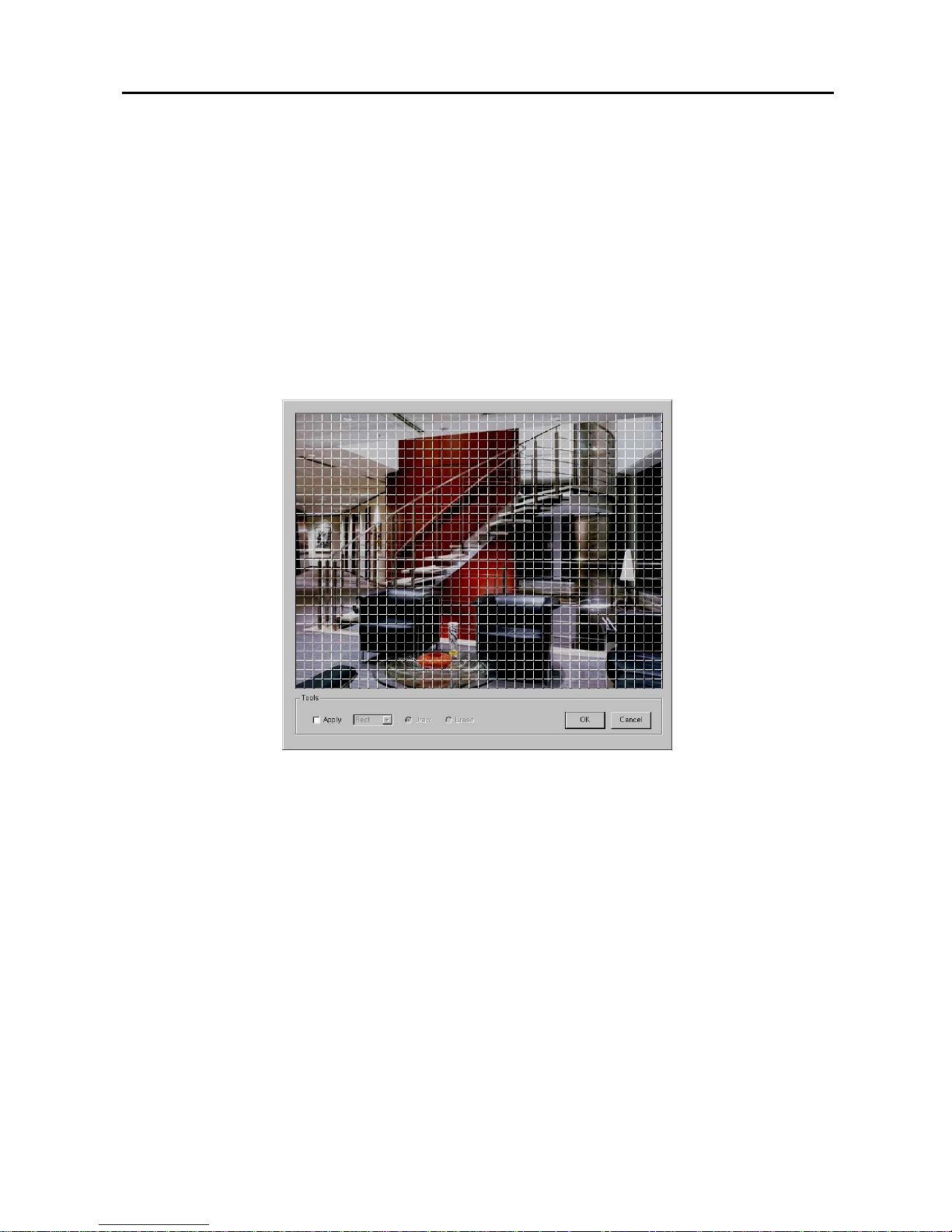
18. Click Set Privacy Area to set up the priva cy area on the image. The selected area set as Privacy Area will NOT
be displayed either in the live m ode or playback m ode. The DVR will display the s elected areas in black, and also
does NOT react to events detected within the area set as P rivacy Area. M ove to Apply and check box and then set
the privacy area zone.
19. The setup screen is made up of a 40x30 grid. First, click the Draw radio button and select a tool to use from the
drop-down list, and then set up the privacy area on the image. Use the tools as follows:
Point — Place the cursor on the image and click t he left mouse bu tton. A single bo x appears where the cursor is.
Line — This tool can be used to draw irregular shapes. Place the cursor where you want to start the line. Hold
down the left mouse button and drag the cursor to where you want the end of the line. Release the mouse button
and a group of boxes appears along the line you drew. You can draw lines around shapes by repeating this
process.
Rectangle — Hold down the left mouse button an d drag the curs or in an y direct ion. A re ctang le appears . Onc e
the rectangle is the size you want, release the mouse button and the rectangle fills with boxes.
Fill — When using the fill tool, clicking the mouse will fill that area of the imag e with boxes. I f a shape has b een
drawn with the line tool, clicking inside will fill the area with boxes. Clicking outside the area will fill the outer
area with boxes. If no shapes have been drawn, the entire screen will fill with boxes.
NOTE: When you select the Erase, you can use the tools as described above to delete boxes.
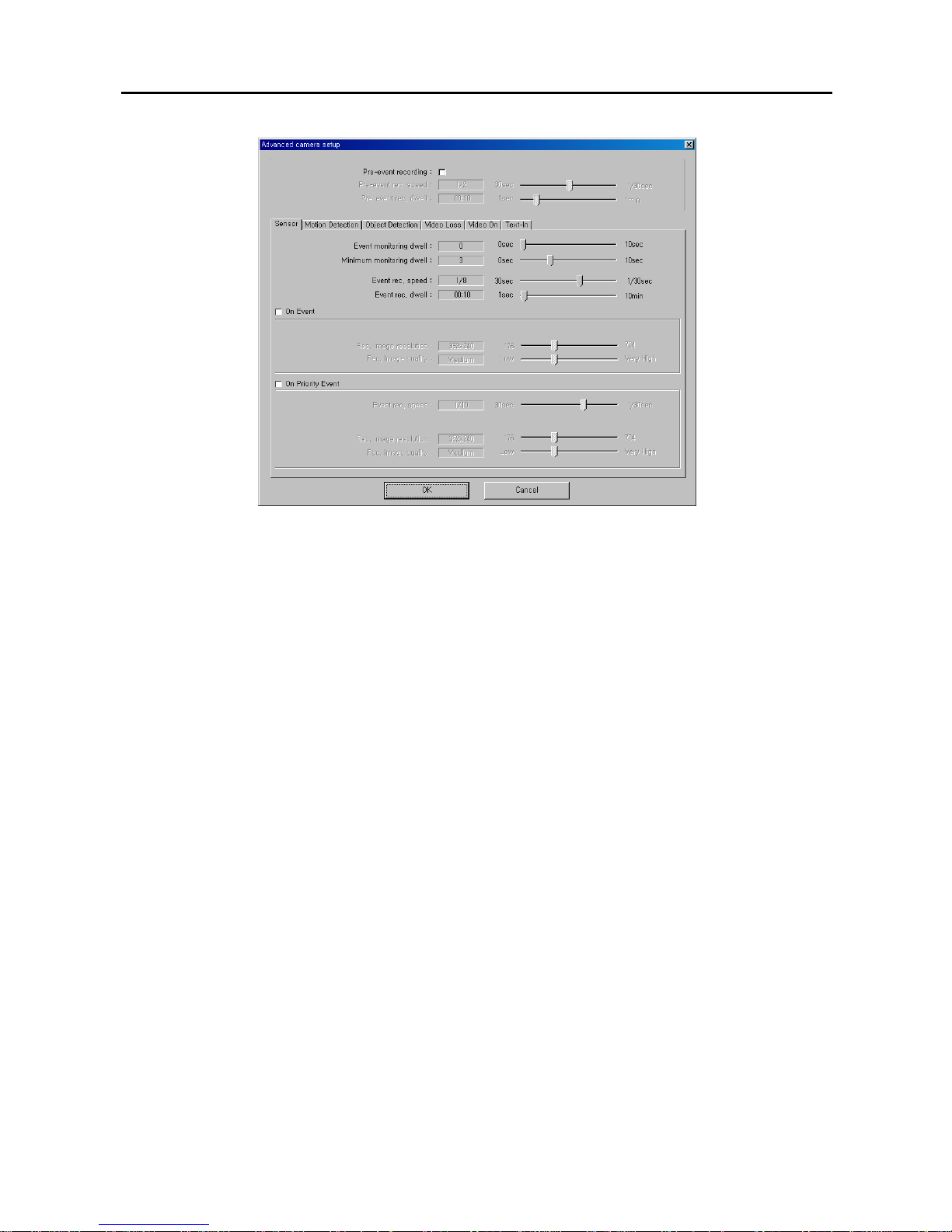
20. Click Advanced Setup... to select an advanced camera setup. You can set up the pre-even t record ing and ev ent
recording options for each event.
User’s Manual
18
21. Move to Pre-event recording, and check the box to enable the pre-event recording.
NOTE: Pre-event recording cannot be configured for cameras 17 to 32.
22. Move to Pre-event rec. speed, and set the recording speed for the pre-event mode by holding down and
dragging the pointer.
23. Move to Pre-event rec. dwell, and set the duration of pre-event recording by holding down and dragging the
pointer.
24. Select the event tab to set up and set the Event monitoring dwell, Minimum monitoring dwell, Event rec.
speed and Event rec. dwell for the event-driven mode by holding down and dragging the pointer.
25. Move to On event, and check the box if you want to use an advanced setup during event activation. Then, s et the
Rec. image resolution and Rec. image quality by holding down and dragging the pointer.
26. Move to On Priority event, and check the box if you want to use an advanced setup during high-priority event
activation. Then, set the Recording speed, Rec. image resolution and Rec. image quality by holding down and
dragging the pointer.
27. You can save your changes by clicking the OK button. Selecting Cancel exits the Advanced camera setup
dialog box without saving the changes.
NOTE: When the recording speed is set to higher than 1/2 sec. (less than two images per second), recorded
audio will NOT be played.
NOTE: The configuration of the Advanced camera setup is also set for all cameras when the Same configuration
for all cameras is selected.
Digital Video Recorder
19
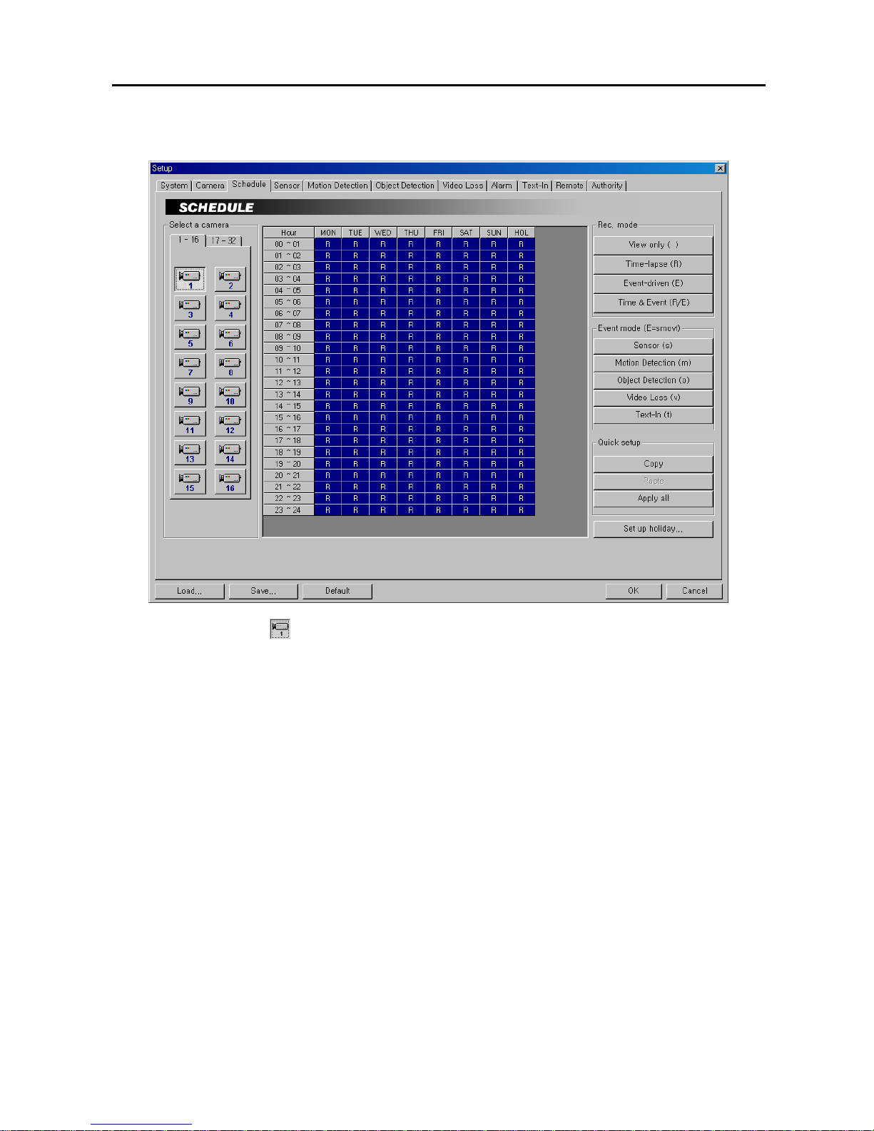
Setting Up Schedules
1. Click the Camera icon.
2. Move to the hour table, and set the recording schedule for each day (MON to SUN) and holidays (HOL). Select
the hours to record by holding down on the recording start time and dragging to recording finish time. The hour
selection will be made through both hours and days. The cells you select will be filled in blue.
3. Click the desired recording mode button under the Rec. mode. The recording modes are: View only (blank),
Time-lapse (R), Event-driven (E) or Time & Event (R/E). If you click the Time-lapse button, an R will
display in the selected cells. Nothing displays when selecting View only.
NOTE: The DVR provides four different recording modes. View only mode — No recording will be made during
selected hours. Time-lapse mode — Time-lapse recording will be made during selected hours.
Event mode — Event-driven recording will be made during selected hours. Time & Event mode — Time-lapse
recording will be made during selected hours and the DVR will go into the event-driven recording mode during
selected hours when an event occurs.
4. Click the desired event(s) button under the Event mode (E=smovt) to be associate with the event recording
mode. Click the event button to toggle On and Off. Various recording modes (e.g. R, R/s, s, mo, smov, R/smov,
R/E, etc) may display in the time table according to settings of user defined Event modes. If you select all
available events, and E will display in the selected cells.
NOTE: Video Loss (v) in Event mode includes both video loss and video obscuration detection.
5. Use the Quick setup to adjust the current settings of the selected camera to another camera. Click the Copy
button, and select another camera to be scheduled by clicking the camera icon in the same dialog box, and then
click the Paste button.
6. Click the Apply all button if you want to adjust the current settings to all cameras.
User’s Manual
20
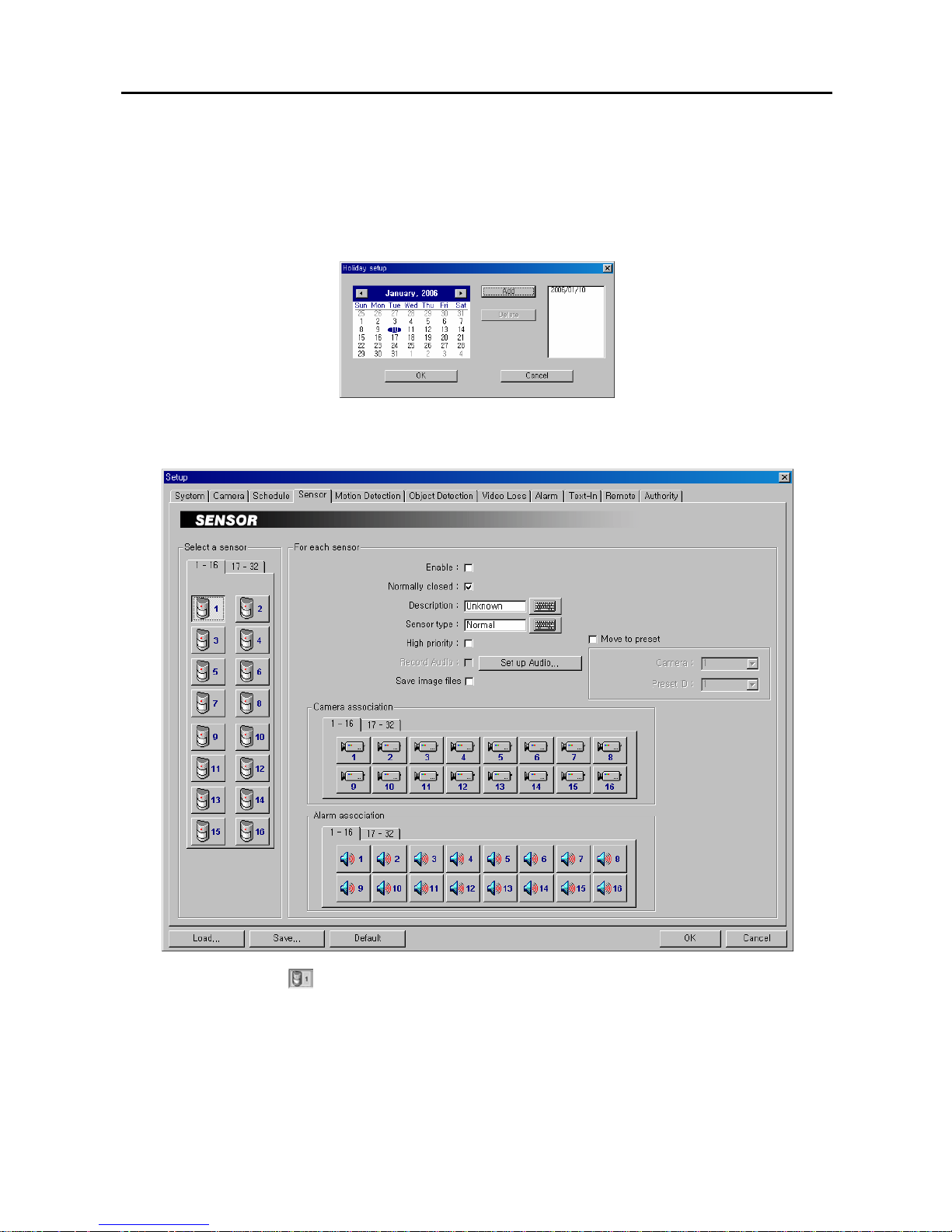
7. Click the Set up holiday... button to set up holidays. This function compensates for different holidays in
different countries. Click the date in the calendar you want as a holiday, and click the Add button. The selected
date will be displayed in the list next to the calend ar. If you want t o delete a holiday, cli ck the Delete button after
selecting the date in the list. Move to other months usi ng the arrow buttons located at the top of th e calendar. You
can save your changes by clicking the OK button. Selecting Cancel exits the Holiday setup dialog box without
saving the changes.
Setting Up Sensors
1. Click the Sensor icon.
NOTE: Selecting 1-16 tab displays sensor channels to 16 and select ing 17-32 tab displays 17 to 32.
2. Move to Enable, and check the box to enable the selected sensor.
3. Move to Normally closed, and set the sensor type to Normally closed (NC) or Normally open (NO). If this box
is checked, it is in the normally closed mode. If it is not checked, it is in the normally open mode.
Digital Video Recorder
21
4. Click the text field beside Description, and enter a sensor title such as "Front Door ". You can use either the actual
keyboard or the virtual keyboard.
5. Click the text field beside Sensor type, and enter a sensor type such as "magnet". You can use either the actual
keyboard or the virtual keyboard.
6. Move to High priority, and check the box to give high priority to the target sensor so the DVR will follow the
advanced camera setup when the target sensor is activated. See the Setting Up Cameras for configuring
advanced camera setup.
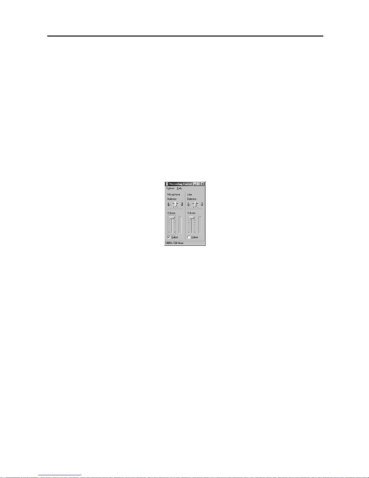
7. Move to Record Audio, and check the box to record audio when a selected s ens or is activated. Recording audio
will be activated when at least one camera is associated with the sensor and the DVR is recording video. When
checking the Record Audio box, click the Set up Audio... button. Select an audio input type from Microphone
or Line-in, and set its balance and volume in the Recording Control dialog box. (Not available for the
PDR16-RMT-RT model)
NOTE: The sound card provides two types of audio input, Microphone and Line-in. Microphone is for an
unamplified source while Line-in is for an amplified source. You must manually select the type of input.
NOTE: The voltages generated by microphones are very much smaller than those used in line level dev ices. If
you were to plug a Microphone into the soundcard Line in, you would never record anything.
8. Move to Save Image Files, and check the box to save the image as a JPG file when a selected sensor is activated.
The file will be saved in the temp/RecordExt under program installation folder automatically. The Save Image
files function operates regardless of the recording schedule.
NOTE: The hard disk drive for saving image files must have at least 700MB free space.
NOTE: The recording speed might decrease when the image files from multiple cameras are saved at the same
time.
9. Move to Move to preset, and check the box to move the target camera to the preset location when a selected
sensor is activated. Select the camera and preset ID from a drop-down list. Preset values can be set individually
by the user who logs in the system.
10. Move to Camera association, and click the camera icon to ass ociate it wi th a selected sensor. Up to 32 camer as
can be selected. Video from associated camera(s) will be recorded when a related sensor is activated.
NOTE: Selecting 1-16 tab displays camera channels 1 to 16 and selecting 17-32 tab displays 17 to 32.
11. Move to Alarm association, and click the alarm icon to be associated with a selected sensor. The alarm will go
off when a related sensor is activated.
NOTE: Selecting 1-16 tab displays alarm channels 1 to 16 and selecting 17-32 tab displays 17 to 32.
User’s Manual
22
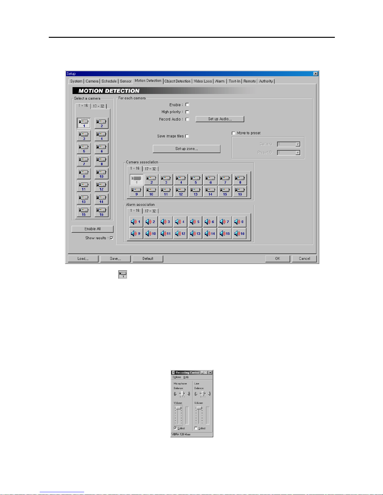
Setting Up the Motion Detection
1. Click the Camera icon.
2. Move to Enable All, and click the button to enable motion detection for all cameras.
3. Move to Enable, and check the box to enable motion detection for the selected camera.
4. Move to High priority, and check the box to give high priority to the target camera. The DVR will follow the
advanced camera setup when the target camera detects motion. See the Setting Up Cameras for configuring
advanced camera setup.
5. Move to Record Audio, and check the box to record audio when a selected camera detects motion. Recording
audio will be activated when the DVR is recording video. When checking the Record Audio box, click the Set
up Audio... button. Select an audio input type from Microphone or Line-in, and set its balance and volume in the
Recording Control dialog box. (Not available for the PDR16-RMT-RT model)
NOTE: The sound card provides two types of audio input, Microphone and Line-in. Microphone is for an
unamplified source while Line-in is for an amplified source. You must manually select the recording input type.

Digital Video Recorder
23
6. Move to Save Image Files, and check the box to save the image as a JPG file when a selected camera detects
motion. The file will be saved in the temp/RecordExt under program installation f older automatically. The Save
Image files function operates regardless of the recording schedule.
NOTE: The hard disk drive for saving image files must have at least 700MB free space.
NOTE: The recording speed might decrease when the image files from multiple cameras are saved at the same
time.
7. Move to Move to preset, and check the box to move the target camera to the preset location when a selected
camera detects motion. Select the camera and preset ID from a drop-down list. Preset values can be set
individually by the user who logs in the system.
8. Click the Set up zone... button, and a zone setup window appears.
9. The setup screen is made up of a 40x30 grid. First, click the Draw radio button and select a tool to use from the
drop-down list, and then set up the detection zone on the image. See the Setting Up Cameras – Set Privacy
area section for setting up the detection zone.
10. Move to Sensitivity, and set the motion detection sensitivity (1 to 5) by holding down and dragging the pointer.
NOTE: The higher the number, the more sensitive it is.
11. Move to Min. size, and set the minimum number of blocks (1 to 100). If you set the Min. size value to 10, the
DVR will only react to the motion when it detects motion (activity) in at least 10 connected blocks within the
selected zone established in step 9. The Min. size should not exceed the selected block numbers for detection.
NOTE: When selecting multiple detection area groups, the minimum number of blocks (Min. size) should not
exceed the block numbers of the smallest detection area.
12. Move to Max. size, and set the maximum number of blocks (from the preset Min. size value to 1200 ). If you set
the Max. size value to 100, the DVR will ignore the motion which exceeds the 100 blocks.
13. Move to View Result, and check the box to see detection results. You can check that sensitivity and minimum
size are set correctly using this feature. You can save your changes by clicking the OK button. Selecting Cancel
exits the dialog box without saving the changes.
14. Move to Show results, and check the box to show detection results on the monitoring image.
User’s Manual
24
15. Move to Camera association, and click the camera icon to associ ate it with the ca mera selected step 1. If motion
is detected by one camera, other cameras can be associated with it so that video will also be recorded from the
associated cameras.
16. Move to Alarm association, and click the alarm icon to associate it with a selected sensor. Th e alarm will go off
when a selected camera detects the motion.
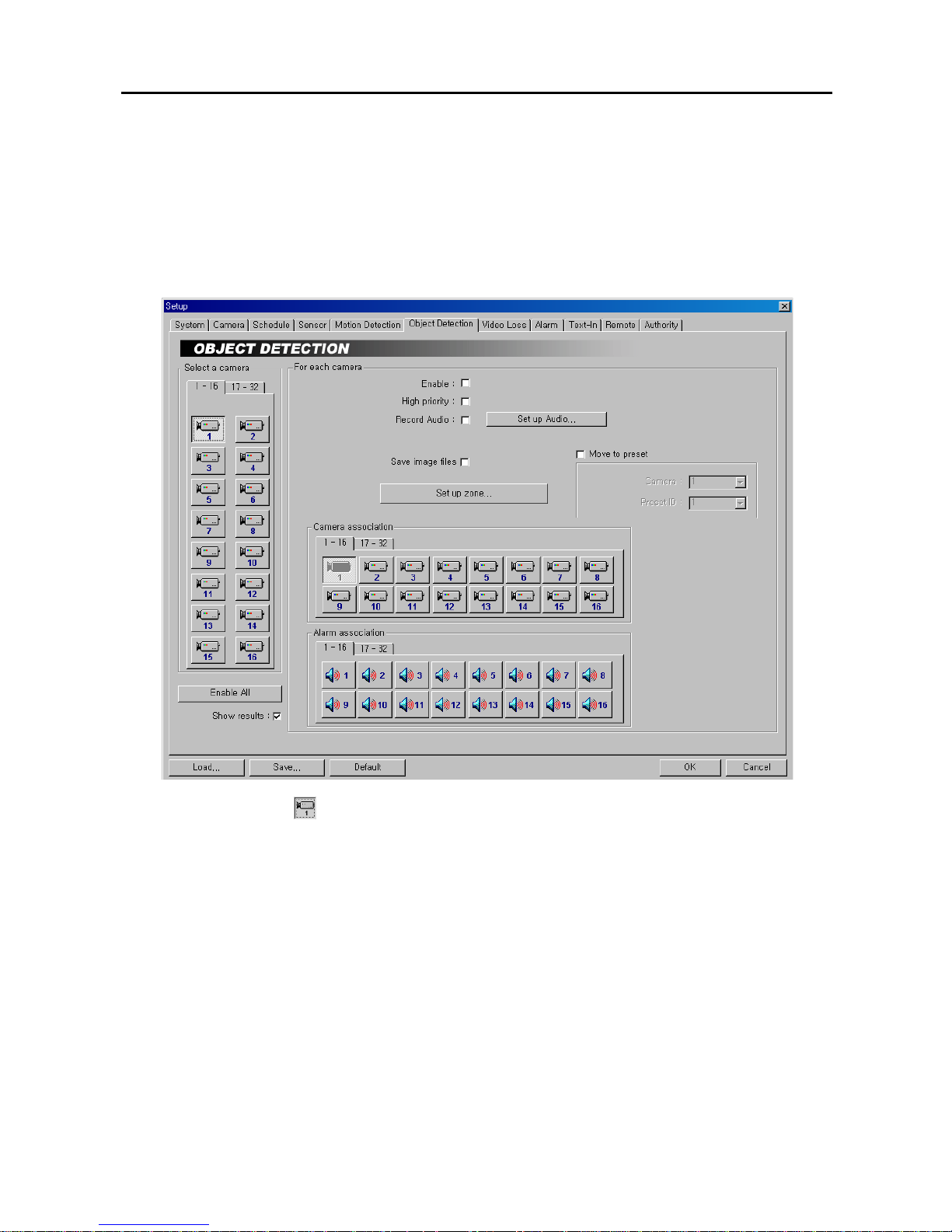
Setting Up the Object Detection
1. Click the Camera icon.
2. Move to Enable All, and click the button to enable Object Tracker function for all cameras.
3. Move to Enable, and check the box to enable Object Tracker function for the selected camera. If the Object
Tracker is selected, the DVR will detect the changes on the image compared to the reference image during the
preset dwell time.
4. Move to High priority, and check the box to give high priority to the target camera. The DVR will follow the
advanced camera setup when the object tracker detects changes on the image of the selected camera. See the
Setting Up Cameras for configuring advanced camera setup.
5. Move to Record Audio, and check the box to reco rd audio when a selected camera detects changes on the image.
Recording audio will be activated when the DVR is recording video. When checking the Record Audio box,
click the Set up Audio... button. Select an audio input type from Microphone or Line-in, and set its balance and
volume in the Recording Control dialog box. (Not available for the PDR16-RMT-RT model)
NOTE: The sound card provides two types of audio input, Microphone and Line-in. Microphone is for an
unamplified source while Line-in is for an amplified source. You must manually select the recording input type.
 Loading...