

Page 1
Page 2

Page 3
Digital Video Recorder
i
WARNING
RISK OF ELECTRIC SHOCK
DO NOT OPEN
WARNING: TO REDUCE THE RISK OF ELECTRIC SHOCK,
DO NOT REMOVE COVER (OR BACK).
NO USER-SERVICEABLE PARTS INSIDE.
REFER SERVICING TO QUALIFIED
SERVICE PERSONNEL.
The lightning flash with arrowhead symbol, within an equilateral triangle, is intended to alert
the user to the presence of uninsulated "dangerous voltage" within the product's enclosure
that may be of sufficient magnitude to constitute a risk of electric shock.
The exclamation point within an equilateral triangle is intended to alert the user to the presence
of important operating and maintenance (servicing) instructions in the literature accompanying
the appliance.
COMPLIANCE NOTICE OF FCC:
THIS EQUIPMENT HAS BEEN TESTED AND FOUND TO COMPLY WITH THE LIMITS FOR A CLASS A DIGITAL
DEVICE, PURSUANT TO PART 15 OF THE FCC RULES. THESE LIMITS ARE DESIGNED TO PROVIDE
REASONABLE PROTECTION AGAINST HARMFUL INTERFERENCE WHEN THE EQUIPMENT IS OPERATED IN
A COMMERCIAL ENVIRONMENT. THIS EQUIPMENT GENERATES, USES, AND CAN RADIATE RADIO
FREQUENCY ENERGY AND IF NOT INSTALLED AND USED IN ACCORDANCE WITH THE INSTRUCTION
MANUAL, MAY CAUSE HARMFUL INTERFERENCE TO RADIO COMMUNICATIONS. OPERATION OF THIS
EQUIPMENT IN A RESIDENTIAL AREA IS LIKELY TO CAUSE HARMFUL INTERFERENCE, IN WHICH CASE
USERS WILL BE REQUIRED TO CORRECT THE INTERFERENCE AT THEIR OWN EXPENSE.
WARNING: CHANGES OR MODIFICATIONS NOT EXPRESSLY APPROVED BY THE PARTY RESPONSIBLE
FOR COMPLIANCE COULD VOID THE USER’S AUTHORITY TO OPERATE THE EQUIPMENT.
THIS CLASS OF DIGITAL APPARATUS MEETS ALL REQUIREMENTS OF THE CANADIAN INTERFERENCE-
CAUSING EQUIPMENT REGULATIONS.
The information in this manual is believed to be accurate as of the date of publication. We are not responsible for any
problems resulting from the use thereof. The information contained herein is subject to change without notice. Revisions
or new editions to this publication may be issued to incorporate such changes.
Page 4
User’s Manual
ii
Important Safeguards
1. Read Instructions
All the safety and operating instructions should be read before the
appliance is operated.
2. Keep Instructions
The safety and operating instructions should be kept for future
reference.
3. Cleaning
Unplug this equipment from the wall outlet before cleaning it. Do
not use liquid aerosol cleaners. Use a damp soft cloth for cleaning.
4. Attachments
Never add any attachments and/or equipment without the approval
of the manufacturer as such additions may result in the risk of fire,
electric shock or other personal injury.
5. Water and/or Moisture
Do not use this equipment near water or in contact with water.
6. Accessories
Do not place this equipment on an unstable cart, stand or table. The
equipment may fall, causing serious injury to a child or adult, and
serious damage to the equipment. Wall or shelf mounting should
follow the manufacturer's instructions, and should use a mounting
kit approved by the manufacturer.
This equipment and cart combination should be moved with care.
Quick stops, excessive force, and uneven surfaces may cause the
equipment and cart combination to overturn.
7. Ventilation
Slots and openings in the cabinet and the back or bottom are provided
for ventilation, and to ensure reliable operation of the equipment and
to protect it from overheating. These openings must not be blocked
or covered. Do not block these openings or allow them to be blocked
by placing the equipment on a bed, sofa, rug, or bookcase. Ensure that
there is adequate ventilation and that the manufacturer’s instructions
have been adhered to.
8. Power Sources
This equipment should be operated only from the type of power source
indicated on the marking label. If you are not sure of the type of
power, please consult your equipment dealer or local power company.
9. Power Cords
Operator or installer must remove power and other connections before
handling the equipment.
10. Lightning
For added protection for this equipment during a lightning storm,
or when it is left unattended and unused for long periods of time,
unplug it from the wall outlet and disconnect the antenna or cable
system. This will prevent damage to the equipment due to lightning
and power-line surges.
11. Overloading
Do not overload wall outlets and extension cords as this can result
in the risk of fire or electric shock.
12. Objects and Liquids
Never push objects of any kind through openings of this equipment
as they may touch dangerous voltage points or short out parts that
could result in a fire or electric shock. Never spill liquid of any kind
on the equipment.
13. Servicing
Do not attempt to service this equipment yourself. Refer all servicing
to qualified service personnel.
14. Damage requiring Service
Unplug this equipment from the wall outlet and refer servicing to
qualified service personnel under the following conditions:
A. When the power-supply cord or the plug has been damaged.
B. If liquid is spilled, or objects have fallen into the equipment.
C. If the equipment has been exposed to rain or water.
D. If the equipment does not operate normally by following the
operating instructions, adjust only those controls that are covered
by the operating instructions as an improper adjustment of other
controls may result in damage and will often require extensive work
by a qualified technician to restore the equipment to its normal
operation.
E. If the equipment has been dropped, or the cabinet damaged.
F. When the equipment exhibits a distinct change in performance —
this indicates a need for service.
15. Replacement Parts
When replacement parts are required, be sure the service technician
has used replacement parts specified by the manufacturer or that have
the same characteristics as the original part. Unauthorized substitutions
may result in fire, electric shock or other hazards.
16. Safety Check
Upon completion of any service or repairs to this equipment, ask
the service technician to perform safety checks to determine that the
equipment is in proper operating condition.
17. Field Installation
This installation should be made by a qualified service person and
should conform to all local codes.
18. Telnet Communication Cable
Caution: To reduce the risk of fire, use only No. 26 AWG or larger
telecommunication line cord.
19. Danger of explosion if battery is incorrectly replaced. Replace
only with same or equivalent type recommended by manufacturer.
Discard used batteries according to the manufacturer’s instruction.
WEEE (Waste Electrical & Electronic Equipment)
Correct Disposal of This Product
(Applicable in the European Union and other European countries with separate collection systems)
This marking shown on the product or its literature, indicates that it should not be disposed with other household wastes at the
end of its working life. To prevent possible harm to the environment or human health from uncontrolled waste disposal, please
separate this from other types of wastes and recycle it responsibly to promote the sustainable reuse of material resources.
Household users should contact either the retailer where they purchased this product, or their local government office, for
details of where and how they can take this item for environmentally safe recycling.
Business users should contact their supplier and check the terms and conditions of the purchase contract. This product should
not be mixed with other commercial wastes for disposal.
Page 5

Digital Video Recorder
iii
Table of Contents
Chapter 1 — Product Information ............................................................................................ 1
Features .............................................................................................................................. 1
System Types ...................................................................................................................... 1
System Diagram .................................................................................................................. 1
Front Panel .......................................................................................................................... 2
Rear Panel ........................................................................................................................... 2
Turning On the DVR ............................................................................................................ 2
Turning Off the DVR ............................................................................................................ 2
Chapter 2 — SmartGuard ........................................................................................................ 3
Overview .............................................................................................................................. 3
Features .............................................................................................................................. 3
Main GUI ............................................................................................................................. 3
Logging In/Out the System ............................................................................................. 4
PTZ ................................................................................................................................. 5
Utility Buttons .................................................................................................................. 5
System Status ................................................................................................................. 5
SmartGuard Setup ............................................................................................................... 6
Setting Up the System .................................................................................................... 6
Setting Up Cameras ........................................................................................................ 9
Setting Up Schedules ................................................................................................... 12
Setting Up Sensors ....................................................................................................... 13
Setting Up the Motion Detection ................................................................................... 14
Setting Up the Video Loss ............................................................................................ 16
Setting Up the Alarm ..................................................................................................... 18
Setting Up the Text-In ................................................................................................... 19
Setting Up the Remote Access ..................................................................................... 20
Setting Up the Authority ................................................................................................ 22
Chapter 3 — SmartSearch ..................................................................................................... 25
Overview ............................................................................................................................ 25
Features ............................................................................................................................ 25
Main GUI ........................................................................................................................... 25
Image Adjustment ......................................................................................................... 26
Playback Control Buttons .............................................................................................. 26
Image Processing Buttons ............................................................................................ 27
Utility Buttons ................................................................................................................ 27
Search and Playback of Recorded Video .......................................................................... 27
Condition Search .......................................................................................................... 27
Time-Lapse Search ....................................................................................................... 29
Saving of Recorded Video ................................................................................................. 30
Save Current Image ...................................................................................................... 31
Save As Video File ........................................................................................................ 31
Save As Clip File ........................................................................................................... 32
Run CD/DVD Burner ..................................................................................................... 32
Clip Player ..................................................................................................................... 33
Printing Current Image ...................................................................................................... 35
Audio Playback .................................................................................................................. 35
Page 6

User’s Manual
iv
Checking Audio Recording Configuration ..................................................................... 35
Checking Audio Playback Configuration ....................................................................... 35
Playing Recorded Audio ............................................................................................... 36
SmartSearch Environment Setup ...................................................................................... 36
General ......................................................................................................................... 36
Network ......................................................................................................................... 37
About ............................................................................................................................. 37
Chapter 4 — SmartBackup .................................................................................................... 39
Manual Backup .................................................................................................................. 40
Setup ................................................................................................................................. 41
CD/DVD Burner ............................................................................................................ 41
Target files for CD/DVD burning ................................................................................... 42
Safeguards on Installing and Using the CD/DVD Burning Program ............................. 42
Chapter 5 — Remote Access ................................................................................................. 43
Recommended BASE System Requirements ................................................................... 43
BASE Program Installation ................................................................................................ 43
SmartBase ......................................................................................................................... 44
Main GUI ....................................................................................................................... 44
Remote Monitoring ........................................................................................................ 46
SmartBase Setup .......................................................................................................... 47
Remote Setup ............................................................................................................... 50
SmartSearch ...................................................................................................................... 50
Remote Playback of Recorded Video ........................................................................... 50
Local Playback of Recorded Video ............................................................................... 51
Remote and Local Playback of Backup Video .............................................................. 51
SmartBackup ..................................................................................................................... 51
Appendix 1 — Accessing Windows ........................................................................................ 53
Appendix 2 — SmartShell ...................................................................................................... 54
Appendix 3 — Network Setup (LAN) ...................................................................................... 55
Appendix 4 — WebGuard ...................................................................................................... 56
Appendix 5 — Time Synchronization ..................................................................................... 61
Appendix 6 — Text-In Query .................................................................................................. 63
Appendix 7 — Connector Pin Outs ........................................................................................ 65
Appendix 8 — Event Log Notices .......................................................................................... 66
Appendix 9 — Protocol for Remote Controlling DVR ............................................................. 67
Appendix 10 — Troubleshooting ............................................................................................ 71
Appendix 11 — Specifications ............................................................................................... 72
Page 7
Digital Video Recorder
1
Chapter 1 — Product Information
FEATURES
Compatible with color cameras and other standard video sources
Video synchronization not required
Pentaplex operation for simultaneous recording, multi-screen viewing, playback, remote monitoring and archiving
Versatile display formats for convenient user interface
Main and Spot monitor outputs
On-screen graphic display including camera title, location, recording status and mode display
Sequence mode available in all screen formats
Hardware watchdog timer function
Programmable motion detection for each camera input using graphic user interface
Various image enhancement functions
Remote monitoring, playback and control via Ethernet
User-friendly interface
Proprietary encryption scheme preventing video from alteration
16-channel alarm input and 1-channel alarm output
NOTE: See Appendix 11 — Specifications for the system specifications of each model.
SYSTEM TYPES
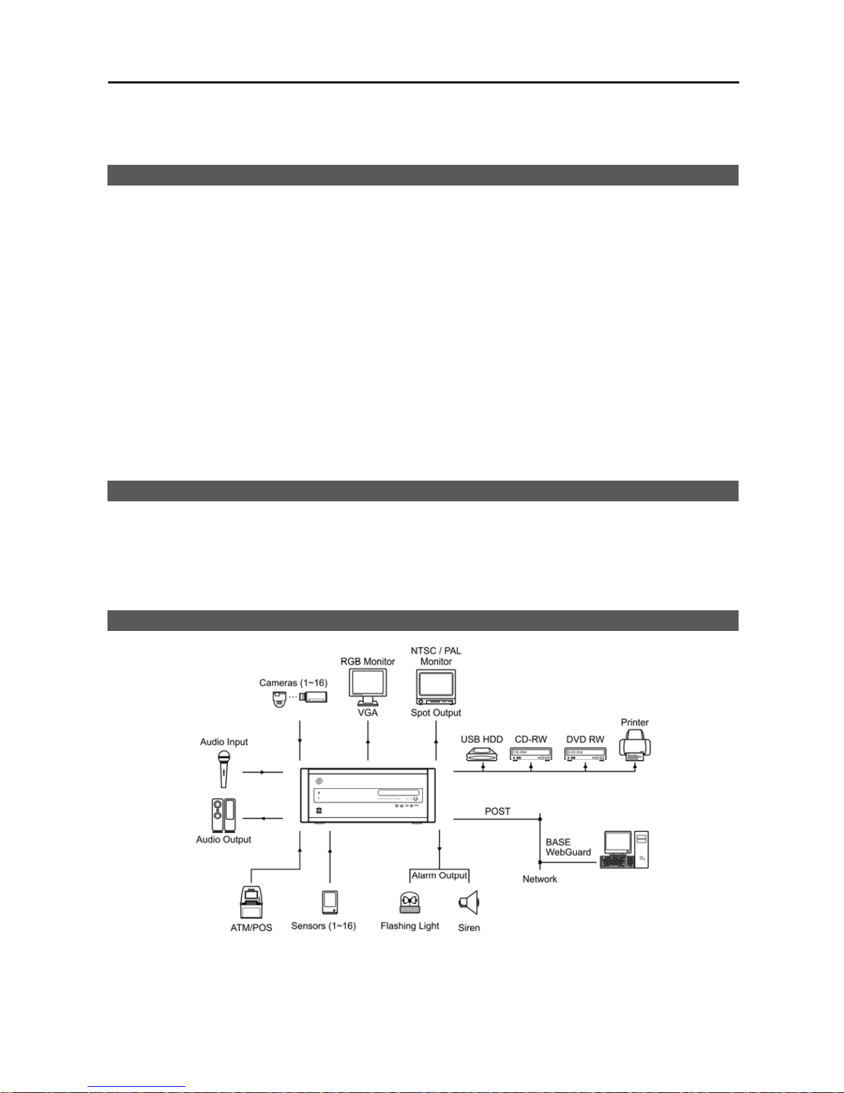
There are two system types: POST DVR system and BASE system. The POST is a complete DVR system with cameras,
and the BASE is a computer with software to access the POST DVR. The BASE can view live or previously recorded
video from the POST DVR. The POST DVR can access another POST DVR when they are networked via LAN,
however, it can only review previously recorded video and cannot view live video from the other POST DVR.
SYSTEM DIAGRAM
Page 8
User’s Manual
2
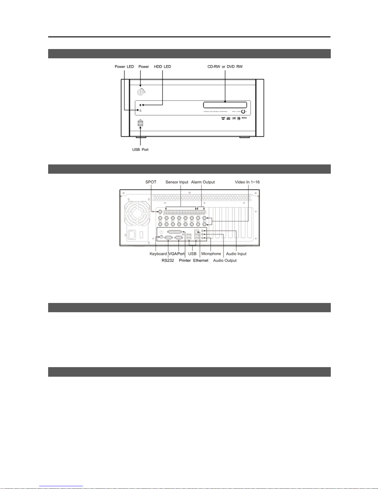
FRONT PANEL
REAR PANEL
NOTE: Windows may not operate properly when using the USB connectors on the front panel of the DVR, depending
on the model type of the USB device. In this case, connect the USB device after Windows boots properly or use
the USB connectors located on the rear panel.
TURNING ON THE DVR
Insert the key in the power switch on the front panel and rotate it count-clockwise. The switch can be left in the ON
position and the key removed. This way the DVR will power up when the ignition is turned.
CAUTION: The system will lock up if the monitor does not have high enough resolution. The DVR requires
1024x768 resolution.
TURNING OFF THE DVR
Click the Power button in the SmartGuard mode or rotate the power switch on the front panel clockwise to turn the
system off.
NOTE: When turning off the system, you must confirm that you want to turn off the unit. You will also be asked for
a user ID and password, or system quit procedure if the Shut Down option was selected for the user’s authorization
during the SmartGuard setup.
CAUTION: Follow the normal shutdown procedures as mentioned above when the system is operating
normally. Turning off the DVR without shutdown procedures can cause damage to the system.
Page 9
Digital Video Recorder
3
Chapter 2 — SmartGuard
OVERVIEW
SmartGuard is powerful surveillance software. It provides multiplexer functions, digital time-lapse recording and
event-driven recording. SmartGuard also provides motion detection, PTZ control and various image enhancement
functions.
NOTE: The first time you turn on the system, it will immediately begin recording. If you have less than 16 cameras,
you must enter the setup screen and deactivate any inputs to which cameras are not connected; otherwise, the
recording speed might be decreased somewhat.
FEATURES
16 channels
Max. 480 images/sec recording (400 images/sec PAL) (PDR16-PC-RT model)
User-friendly interface
Scheduling by camera and time
Time-lapse or event-driven recording
Motion detection function
Audio recording
PTZ control
NOTE: Refer to Appendix 11 — Specifications for the maximum recording speed of each model.
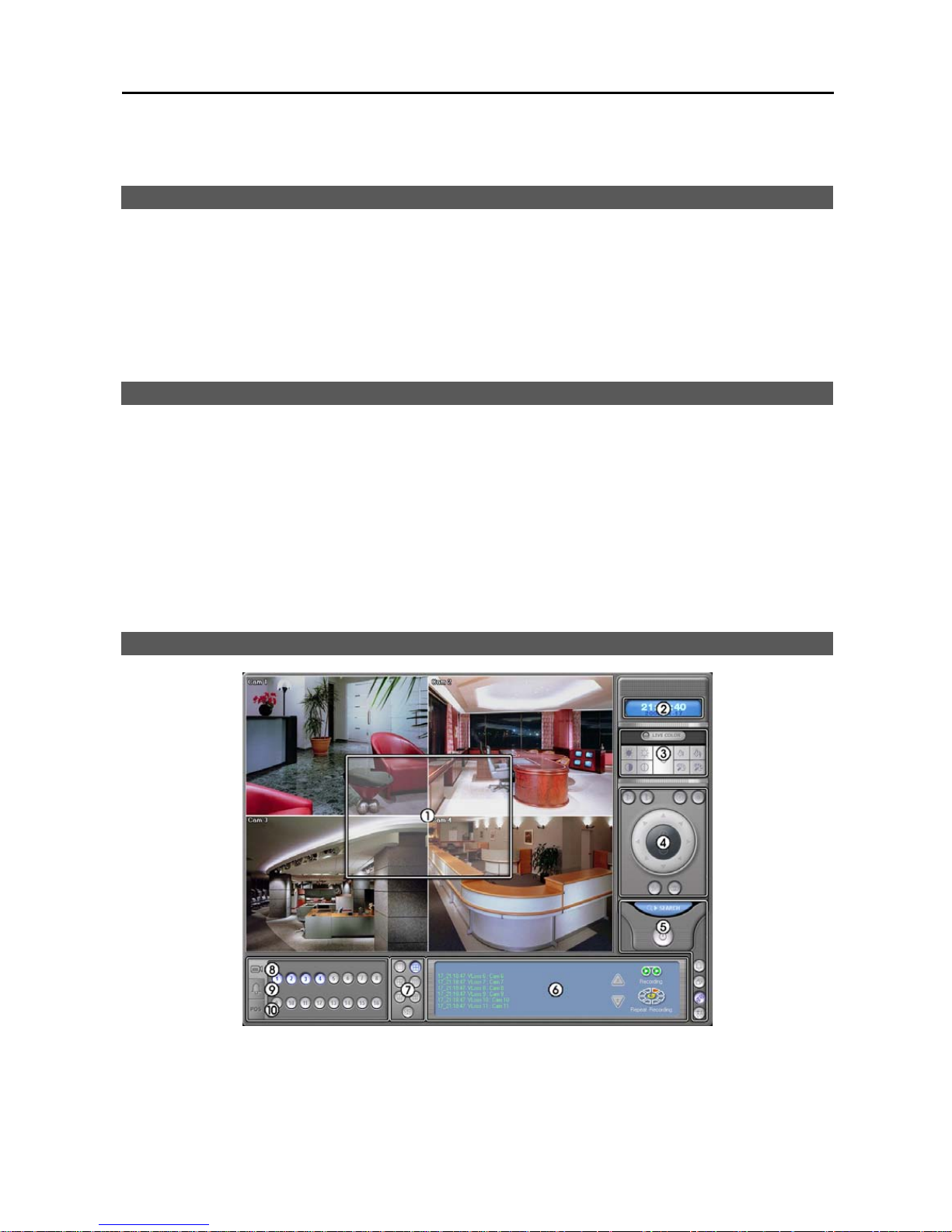
MAIN GUI
Page 10

User’s Manual
4
① Monitoring Screen: Displays monitoring video. Various display formats (single-screen, full-screen, quad, 3+4,
3x3, 2+8, and 4x4) are provided for convenient user interface. Each format can be selected by clicking the screen
buttons shown below. The camera groups for multi-screen formats are composed of cameras 1 to 16 in order. The
following camera groups are displayed on the monitor one at a time according to each display format: 1-4, 5-8, 9-12
or 13-16 in quad mode; 1-7 or 8-16 in 3+4 mode; 1-9 or 10-16 in 3x3 mode; 1-10 or 11-16 in 2+8 mode. The user
can select which camera group is displayed by clicking any camera button in a group from camera buttons shown
below. Information including camera title, recording mode, and recording status can be displayed on the image. Go
to Setting Up the System (p. 6) and Setting Up Cameras (p. 9) in the SmartGuard Setup section, and place
a check in the Show OSD box to display the OSD information.
② Clock: Displays date and time. Click the left mouse button on the clock area to set date display (MM-DD-YYYY/...)
and time display (12 Hours/24 Hours) formats. Click the right mouse button on the clock area to set date, time
and time zone.
CAUTION: If you change the time, images dated later than t he new date/time are deleted. Back up the im ages
if you want to save them.
③ Image Adjustment: Click to display image adjustment buttons. You can adjust the
brightness, contrast, hue and saturation of live or record image by clicking the designated
buttons. Click the Default button to reset them to the default settings. These adjustments
should not be used to correct improperly set cameras or monitors. Also, it is important
that images are properly adjusted. These adjustments cannot make up for improperly
adjusted images when the images are recorded.
④ PTZ: Displays PTZ control buttons. Refer to the PTZ section (p. 5) for details.
⑤ Utility Buttons: See the Utility Buttons section (p. 5) for details.
⑥ System Status: Displays operating mode, the remaining hard disk space and the type of hard disk usage, and also
displays system events. Refer to the System Status section (p. 5) for details.
⑦ Screen Mode Buttons: Click the desired screen mode. Move the cursor to that image and double click the left
mouse button to view a specific image in the single-screen mode. Click the left mouse button in the window to return
to the previous screen mode from the single-screen mode.
⑧ Camera Buttons: Click to display the camera buttons. Clicking the individual camera buttons displays the selected
camera.
⑨ Alarm Control: Click to display alarm control buttons. You can check the alarm status and control the alarm output.
Pressed alarm button is active mode, and released button is inactive mode. The user can active or inactive alarm
output manually by clicking the button when it is released or pressed. If the user disables the alarm during the Alarm
setup on the SmartGuard, the alarm button will be disabled.
⑩ POS: Click to display POS control buttons. The system status window will display the POS data. Click the right
mouse button on the window to toggle two display modes: POS data display mode, and event log including POS
data display mode. The POS button LED will be lit while the data is coming from the POS. If you do not want to
display the data from the POS, release the target POS number button. If the user disables the POS device during
the Text-In setup on the SmartGuard, the POS button will be disabled.
Logging In/Out the System
Log In: Click any function button on the main GUI of SmartGuard after logging out, the following User Login dialog
box appears. Enter the User ID and Password and then click the OK button if you want to log in the system.
Log Out: Click the Power button after logging in, the Quit dialog box appears. Select System quit to quit the program
or select logout to log out the system.
NOTE: When No local login is selected during the Setting Up the Authority setup section (p. 22), the DVR does
not ask login procedure.
NOTE: When you forgot the password, ask your dealer or distributor.
Page 11
Digital Video Recorder
5
PTZ
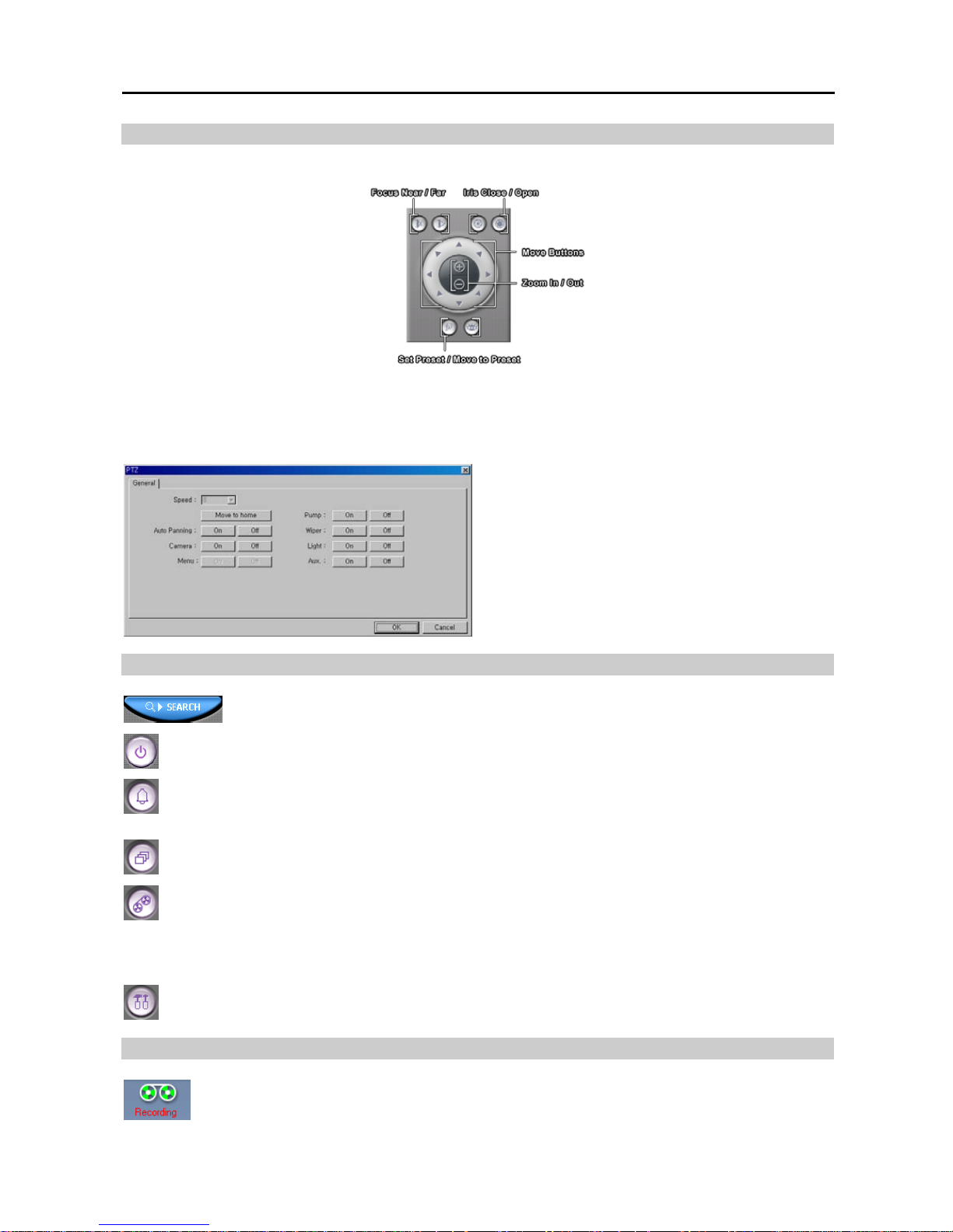
The DVR provides transmission functions, and you can control popular PTZ devices and dome cameras.
NOTE: Up to 128 presets can be set, depending on the specification of installed PTZ devices or dome cameras.
Make sure available preset numbers first to make the PTZ preset function work properly.
NOTE: If you want to set up the advanced PTZ control, place the cursor on the PTZ control panel, and click the
right mouse button. Depending on the camera specifications, some features may not be supported.
Speed: Set the pan/tilt speed (from 1 to 16). The
higher the number, the faster it moves.
Move to origin: Click the button if you want to move
the camera to the origin position.
Auto Panning: Enables or disables auto panning.
Camera: Turns on or turns off the camera.
Menu: Enables or disables the menu function.
Pump/Wiper/Light/Aux: Enables or disables pump,
wiper, light and other available functions.
Utility Buttons
Accessing SmartSearch: Click the button to run the SmartSearch.
Power: Click the button to quit or log out the system. Refer to the Logging In/Out the System section
(p. 4) for details.
Manual Alarm Output: In general, the alarm is activated automatically when any related sensor is activated.
However, the user can activate all the alarm output manually by clicking this button while it is released or
deactivate all the alarm output by clicking the button when it is pressed.
Auto Sequencing: Click the button to sequence the cameras in order. Whenever you click the button, it
toggles between On and Off. The switching interval can be set during the system setup.
Record: The record mode is selected when this button is clicked. SmartGuard returns to view only mode
automatically when it is unable to record (for example, when the hard disk is full).
NOTE: The DVR records only in accordance with the recording schedule, which can be set during the system setup.
Before you install the DVR, you need to fully understand the recording schedule. Note also that clicking this recording
mode button only prepares the DVR for recording. In this state, the DVR will follow the recording schedule.
Setup: Click the button to display a Setup dialog box. Refer to the SmartGuard Setup section (p. 6) for
details.
System Status
Mode Status: There are two operating modes – View only mode and Recording mode. The SmartGuard
records images only in the Recording mode.
Page 12
User’s Manual
6
HDD Indicator: Shows the remaining hard disk space and the type of hard disk usage. Go to the
SmartGuard Setup – Setting Up the System section (p. 6), and select between Once and
Recycle for HDD usage. Placing the mouse cursor on an image displays the total recording days.
NOTE: Once (displayed as Disk available: **%) records until the hard disk is full and then stops. Recycle (displayed
as Repeat Recording) records over the oldest images when the hard disk is full.
Event Logging: Displays the system events. To scroll up and down the list, hold down
the left mouse button on the list and move the cursor up and down, or roll the mouse
wheel on the list. Recorded events are underlined in the list, and clicking the underlined
event initiates the SmartSearch program and moves to the timetable allowing you to
play back the event-detected video. The display information of the event log is as
follows: ‘Date’_‘Time’ ‘Event type’ ‘Camera No.’ : ‘Camera title’
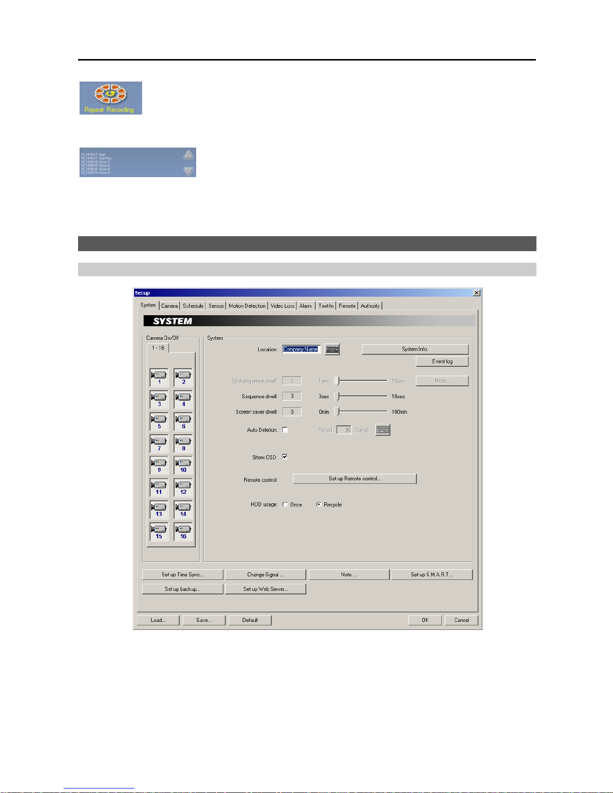
SmartGuard SETUP
Setting Up the System
Camera On/Off: Enables or disables the camera.
Location: If you have a keyboard attached to your unit, enter a location name such as “Main Office.” If you do not
have a keyboard connected to the unit, clicking the keyboard icon will display a virtual keyboard on which you can
type by clicking the letters.
Spot sequence dwell: Set the sequence dwell time for the Spot monitor by holding down and dragging the pointer.
If you set the value to 3 seconds, the camera display will sequence every three seconds on the Spot monitor.
Page 13
Digital Video Recorder
7
Sequence dwell: Set the sequence dwell time for the main monitor by holding down and dragging the pointer. If
you set the value to 3 seconds for the Sequence dwell, the camera display will sequence every three seconds on the
Main monitor.
Screen saver dwell: Set the screen saver dwell time for the display image. The screen saver will be activated if
there is no keyboard or mouse operation during the preset dwell time.
Auto Deletion: Check the box if you want to delete the video recorded earlier than user-defined period. When
checking the Auto deletion box, move to Period and set the period to keep the recorded video. e.g. If you check
the Auto deletion box, and set 30 days in the Period box, the DVR will automatically delete the video which is older
than 30 days from the current day.
Show OSD: Check the box if you want to display OSD information on the image. OSD information includes camera
title, recording mode, recording status and event detection status.
NOTE: A R indicates the target camera is in the Time-lapse recording schedule mode. An E indicates it is in the
Event-driven recording mode. A R/E indicates it is in the Time & Event recording mode. A R located at the bottom-
right corner indicates the DVR is recording video, and the blink rate of the R relates to the recording speed. A
icon displaying at the bottom-left corner indicates that motion detection event occurs.
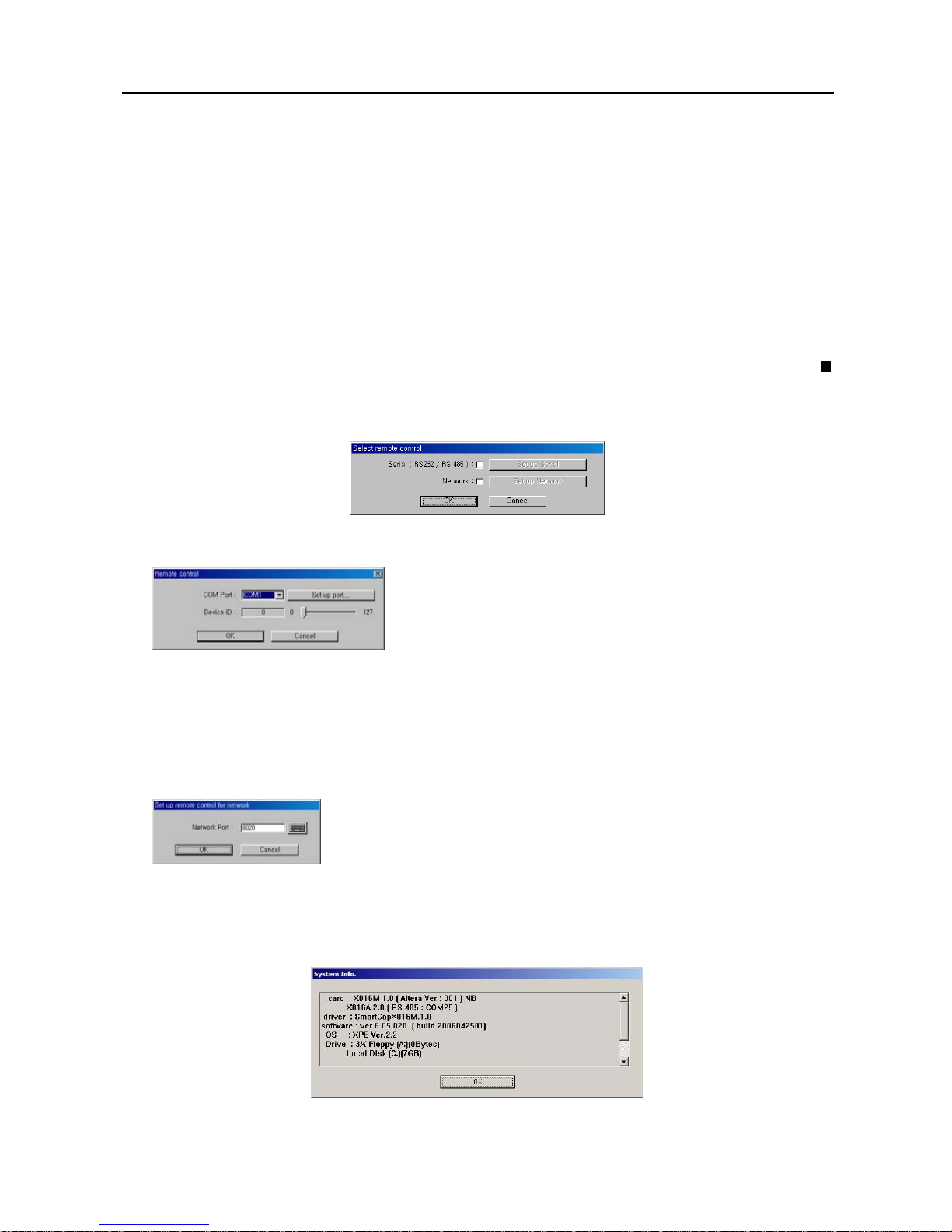
Remote control: Click the Set up Remote control... button when the DVR is controlled remotely using the serial
communication signals or via network connections.
– Serial (RS232/RS485): Check the box and click the Set up Serial when the DVR is controlled remotely using
the serial communication signals.
Select the DVR's COM port to use from the drop-down list. Click the
Set up port... button, and set the Baud rate from 300 to 256,000. Select
Parity from None, Even or Odd parity. Select Data bit from 7 bit or 8
bit format. Select Stop bit from 1 bit or 2 bits from the drop-down list.
Move to Device ID, and set the device ID number from 0 to 127 using the
slide bar. Refer to Appendix 9 — Protocol for Remote Controlling
DVR for details.
NOTE: When using the RS232 port, select COM 1 from the COM Port drop-down list. When using the RS485
port, select the given COM Port number. To check the given COM port number, please refer to the installed
card information displayed on the System Info. dialog box by clicking the System Info. button.
– Network: Check the box and click the Set up Network when the DVR is controlled remotely via network
connections. Enter the Network Port number.
NOTE: When selecting the Network remote control for the user’s authorization,
you can control the DVR remotely via network connections. Refer to the
Setting
Up the Authority
section (p. 22) for details.
HDD usage: Select either Once or Recycle. When Once is selected, the DVR stops recording when the hard disk
drive is full. When Recycle is selected, the DVR continues recording when the hard disk drive is full by overwriting
the oldest video.
System Info…: Click the button, and the System Info. dialog box displays the information of the installed cards,
driver, software, hard disk drive, OS and MAC address on the system.
Event log: Displays the event log list of the system.
Page 14
User’s Manual
8
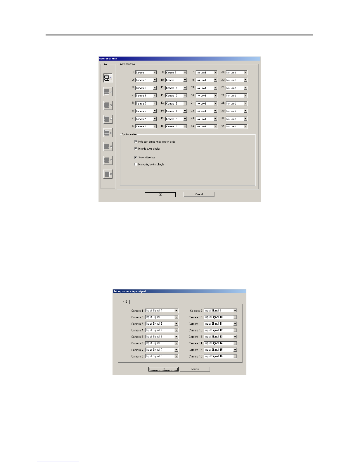
More…: Set up the spot sequence in detail. (PDR16-PC model only)
– Spot Sequence: Select the camera number for each number to sequence or Not Used from a drop-down list.
– Hold spot during single-screen mode: Check the box if you do not want the cameras sequence on the Spot
monitor while the main monitor is set to the single-screen display mode.
– Include event display: Check the box if you want to display any events during spot sequence.
NOTE: Event display will be enabled when you set up the event monitoring during the Camera advanced setup.
Refer to the
Setting Up Cameras section (p. 9) for details.
– Show video loss: Check the box if you want to show the video loss image during spot sequence.
– Monitoring without login: Check the box if you want to view video on the Spot monitor without login.
Set up Time Sync…: Set up the time synchronization if required. Refer to Appendix 5 — Time Synchronization
for details.
Change Signal…: Select the video input signal to each camera number from a drop-down list.
Note…: Set up the note function. The user can add or delete notes. If you want to read the note, select the line and
click the View button. Click the Load button to load the saved note, the Save button to save the current note, and
the Text Save button to save the current note to the text file.
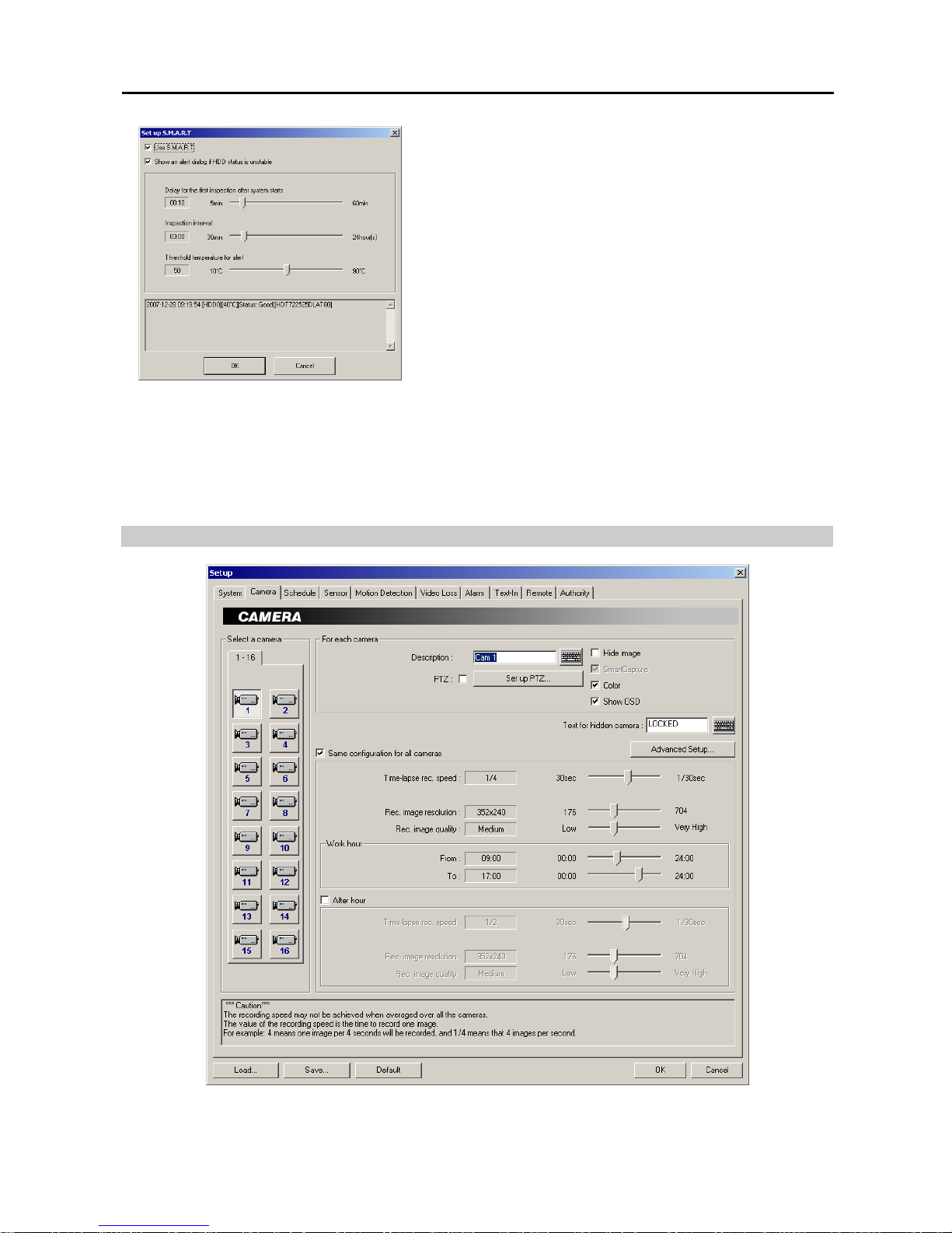
Set up S.M.A.R.T. …: Set up the S.M.A.R.T. function
when the installed hard disk drives support S.M.A.R.T. (Self-
Monitoring, Analysis and Reporting Technology) Monitoring program (Internal hard disk drives only).
Page 15
Digital Video Recorder
9
− Use S.M.A.R.T.: Check the box if you want to use S.M.A.R.T.
function.
− Show an alert dialog if HDD status is unstable: Check the box
if you want to display an alert message when the DVR senses that
the hard disk drive status is Poor. Once the alert message displays,
replacing the hard disk drive as soon as possible is recommended,
usually within 24 hours.
− Delay for the first inspection after system starts: Set the standby
time until the system performs the first inspection after the system
starts.
− Inspection interval: Set the inspection interval.
− Threshold temperature for alert: Set the threshold temperature
of hard disk drives. The DVR logs an event when the temperature
of hard disk drives exceeds the defined threshold.
Set up backup...: Set up backup information. Refer to Chapter 4 — SmartBackup for details.
Set up Web Server...: Set up an IIS (Internet Information Services) for the WebGuard program.
Click the Load... button if you want to load typical settings. Click the Save... button if you want to save the current
settings. Click the Default button if you want to load default settings. You can save your changes by clicking the OK
button. Selecting Cancel exits the dialog box without saving the changes.
NOTE: Only the administrator level user can use the Load, Save and Default buttons.
Setting Up Cameras
CAUTION: The recording speed may not be achieved when averaged over all the cameras.
Page 16
User’s Manual
10
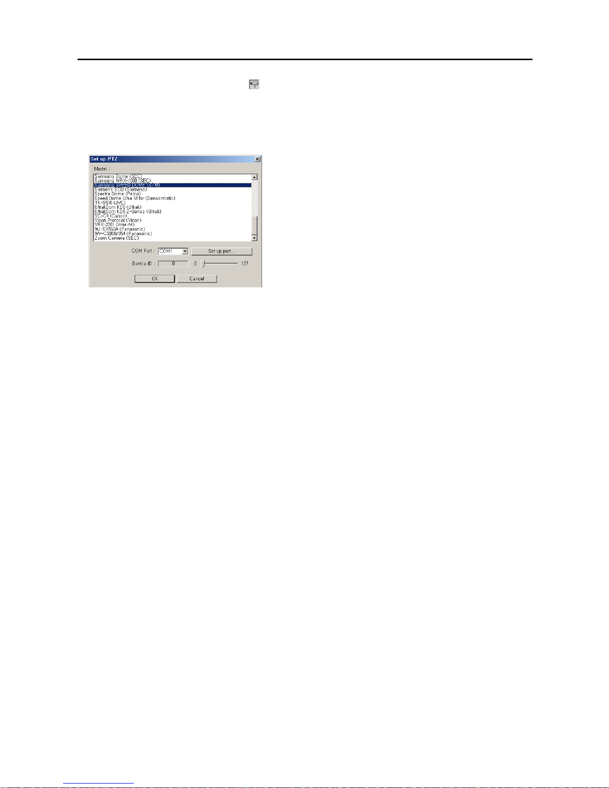
Select a camera: Select a camera icon to set up.
Description: Enter a camera title such as “Front Door”. You can use either the actual keyboard or the virtual keyboard.
PTZ: Check the box to enable pan, tilt and zoom functions. Click the Set up PTZ... button to display the Set up
PTZ dialog box. Select the model of the installed RX device or dome camera from the Model list.
NOTE: To control camera pan, tilt and zoom, you must attach a compatible RX device or dome camera to the DVR.
A list of supported RX devices and dome camera models can be found in the Set up PTZ dialog box.
− COM Port: Select the given COM port number from the drop-down
list. To check the given COM port number, please refer to the
installed card information displayed on the System Info. dialog
box by clicking the System Info. button.
− Set up port…: Click the button to display the Set up COM port
dialog box. Set the Baud rate from 300 to 256,000, select the Parity
from None, Even or Odd parity, select the Data bit from 7 bit
or 8 bit format, select the Stop bit from 1 bit or 2 bits from the
drop-down list.
− Device ID: Set the device ID number from 0 to 127 using the slide
bar.
Hide image: Check the box to hide the image of the selected camera on the monitor. If this box is checked, the
selected camera will not be displayed on the monitor, however, the images from the camera will be recorded while
in the record mode.
Text for hidden camera: Enter the text to be displayed on the hidden camera using the actual keyboard or the virtual
keyboard. If you leave this box empty, the gray screen without any text will be displayed for the hidden camera.
SmartCapture: Check the box to use the SmartCapture technique.
NOTE: The DVR captures the images very quickly using a unique technique called SmartCapture. However, it
is possible that some PAL cameras will have shaky images when using this program. Do not check this box if your
cameras have shaky images.
Color: Check the box when using a color camera. When using a B&W camera, make certain the box is not checked.
This will reduce noise, giving better recorded image quality.
Show OSD: Check the box if you want to show OSD information on the image of selected camera. If you want to
enable Show OSD function, the Show OSD option should be selected during the System setup.
Same configuration for all cameras: Check the box to set all cameras with the same configuration.
Time-lapse rec. speed: Set the recording speed for the time-lapse mode by holding down and dragging the pointer.
You can set the speed from 30 to 1/30 seconds. The value of the recording speed is the time to record one image.
Therefore the lower the value, the more images are recorded during the same time. For example: 30 means one image
per 30 seconds will be recorded, 1 means one image per second, and 1/30 means that 30 images per second.
NOTE: When the recording speed is set to higher than 1/2 sec. (less than two images per second), recorded audio
will NOT be played.
NOTE: The PDR16-PC model has a maximum recording speed of 120 images per second (100 images for PAL),
and this maximum recording speed can be decreased when using more than four cameras. Refer to Appendix 11
— Specifications for the maximum recording speed of each model.
Rec. image resolution: Set the record image size recorded by holding down and dragging the pointer.
NOTE: Higher resolution images require more storage space and will reduce the recording capacity of the hard
disk drive. When set to 640x480 (704x480 (704x576 PAL) for PDR16-PC-RT model), video with lots of motion may
have some artifacts.
Rec. image quality: Set the record image quality by holding down and dragging the pointer. You can select the
resolution from Low, Medium, High or Very High.
NOTE: Higher quality images require more storage space and will reduce the recording capacity of the hard disk drive.
NOTE: The maximum record image size and quality of pre-event recording will be restricted to 320x240 (352x240
(352x288 PAL) for PDR16-PC-RT model) and Medium regardless of setting values of Rec. image resolution and
Rec. image quality in order to maximize the amount of pre-event video to be stored.
Work hour: Set the start time (From) and end time (To) of working hours by holding down and dragging the pointer.
Page 17
Digital Video Recorder
11
NOTE: Work hour set in this menu is applied to the normal camera setup established in during the Time-lapse rec.
speed, Rec. image resolution and Rec. image quality setup, and all hours except the Work hours will be After hour.
After hour: Check the box if you want to set up different recording option during the hours outside hours established
in Work hour. Then, set the Time-lapse rec. speed, Rec. image resolution and Rec. image quality by holding
down and dragging the pointer. Refer to the Time-lapse rec. speed, Rec. image resolution and Rec. image quality
setup
for the available values for each setting.
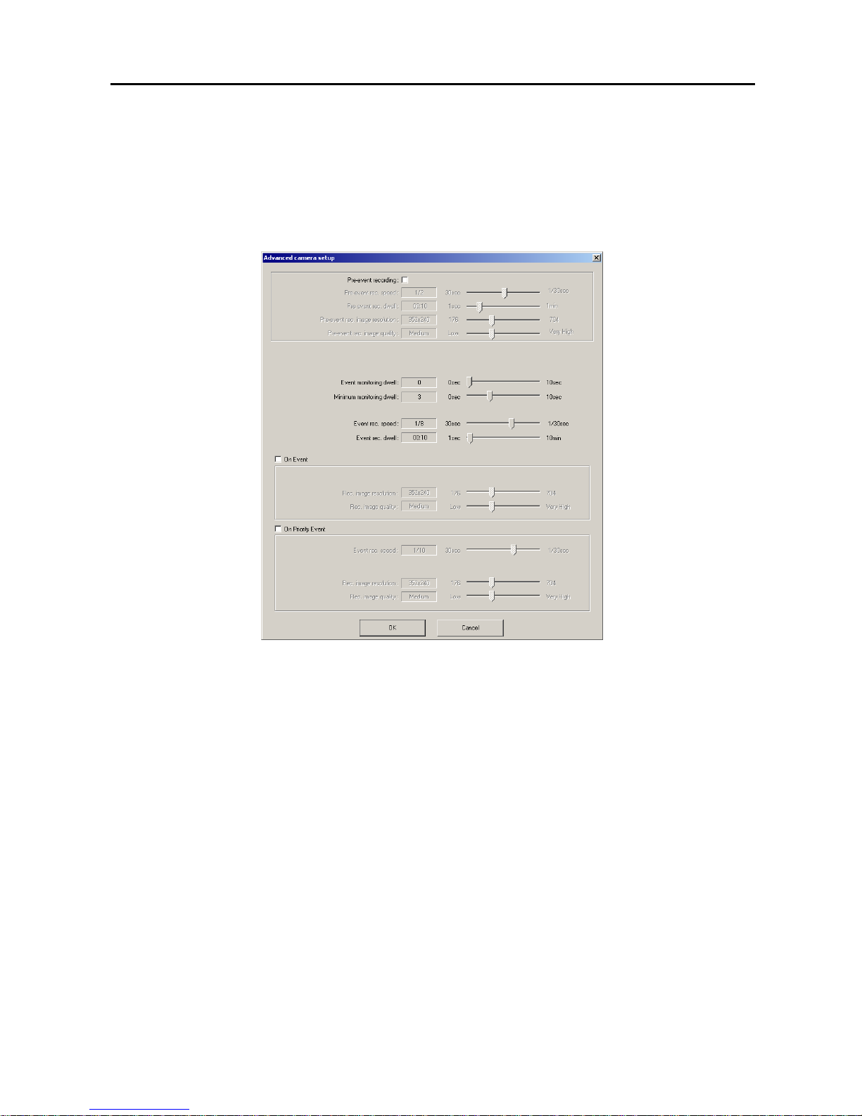
Advanced Setup...: Select an advanced camera setup. You can set up the pre-event recording and event recording
options for each event.
– Pre-event recording: Check the box to enable the pre-event recording.
– Pre-event rec. speed: Set the recording speed for the pre-event mode by holding down and dragging the pointer.
– Pre-event rec. dwell: Set the duration of pre-event recording by holding down and dragging the pointer.
– Pre-event rec. image resolution: Set the record image size by holding down and dragging the pointer.
– Pre-event rec. image quality: Set the record image quality by holding down and dragging the pointer.
– Event monitoring dwell / Minimum monitoring dwell / Event rec. speed / Event rec. dwell: Set the values
for the event-driven mode by holding down and dragging the pointer.
– On Event: Check the box if you want to use an advanced setup during event activation. Then, set the Rec. image
resolution and Rec. image quality by holding down and dragging the pointer.
– On Priority Event: Check the box if you want to use an advanced setup during high-priority event activation. Then,
set the Recording speed, Rec. image resolution and Rec. image quality by holding down and dragging the pointer.
You can save your changes by clicking the OK button. Selecting Cancel exits the Advanced camera setup dialog
box without saving the changes.
NOTE: When the recording speed is set to higher than 1/2 sec. (less than two images per second), recorded audio
will NOT be played.
NOTE: The configuration of the Advanced camera setup is also set for all cameras when the Same configuration
for all cameras is selected.
Page 18
User’s Manual
12
Setting Up Schedules
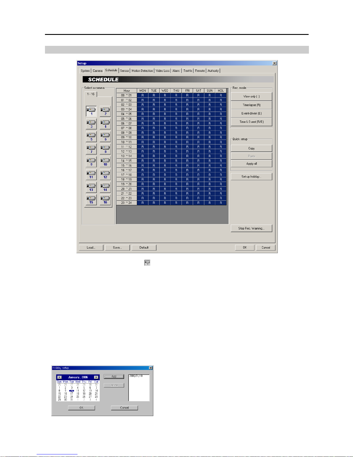
Select a camera: Select a camera icon
to set up.
Hour: Set the recording schedule for each day (MON to SUN) and holidays (HOL). Select the hours to record by
holding down on the recording start time and dragging to recording finish time. The hour selection will be made
through both hours and days. The cells you select will be filled in blue.
Rec. mode: Click the desired recording mode button. If you click the Time-lapse button, an R will display in the
selected cells. Nothing displays when selecting View only.
NOTE: The DVR provides four different recording modes. View only mode — No recording will be made during
selected hours. Time-lapse mode — Time-lapse recording will be made during selected hours. Event mode —
Event-driven recording will be made during selected hours. Time & Event mode — Time-lapse recording will be
made during selected hours and the DVR will go into the event-driven recording mode during selected hours when
an event occurs.
Quick setup: Select the desired button to adjust the current settings of the selected camera to another camera. Click
the Copy button, and select another camera to be scheduled by clicking the camera icon in the same dialog box, and
then click the Paste button. Click the Apply all button if you want to adjust the current settings to all cameras.
Set up holiday...: Set up holidays. This function compensates for different holidays in different countries.
Click the date in the calendar you want as a holiday, and click the
Add button. The selected date will be displayed in the list next to
the calendar. If you want to delete a holiday, click the Delete button
after selecting the date in the list. Move to other months using the
arrow buttons located at the top of the calendar. You can save your
changes by clicking the OK button. Selecting Cancel exits the
Holiday setup dialog box without saving the changes.
Page 19
Digital Video Recorder
13
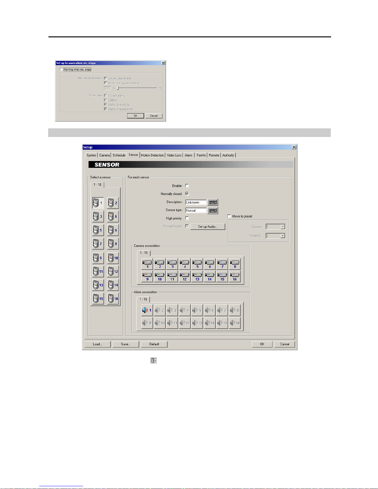
Stop Rec. Warning…: Click the button to notify when recording stops.
Check the Warning when rec. stops box.
− Rec. stoppage reason: Check the Click rec. stop button box to
notify when recording stops by clicking the Recording mode button.
Check the No rec. during specified time box to notify when the
DVR does not record during the preset time (1 to 24 hours).
− On rec. stop: Select how to notify when recording stops.
Setting Up Sensors
Select a sensor: Select a sensor icon
to set up.
Enable: Check the box to enable the selected sensor.
Normally closed: Set the sensor type to Normally closed (NC) or Normally open (NO). If this box is checked, it
is in the normally closed mode. If it is not checked, it is in the normally open mode.
Description: Enter a sensor title such as "Front Door". You can use either the actual keyboard or the virtual keyboard.
Sensor type: Enter a sensor type such as "magnet". You can use either the actual keyboard or the virtual keyboard.
High priority: Check the box to give high priority to the target sensor so the DVR will follow the advanced camera
setup when the target sensor is activated. Refer to the Setting Up Cameras section (p. 9) for configuring advanced
camera setup.
Record Audio: Check the box to record audio. The box will be activated when a camera is associated with the sensor.
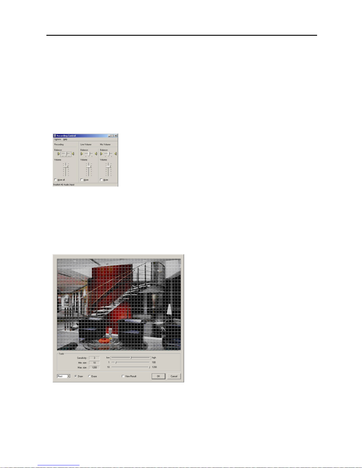
Click the Set up Audio... button, and the Recording Control dialog box appears.
Page 20
User’s Manual
14
Set the audio balance and volume in the Recording column. When checking the Mute
all box or the Mute box in the column of the connected audio input type (Line or Mic),
audio will not be recorded.
NOTE: Make certain you comply with all local and federal laws and regulations
when recording audio.
NOTE: Audio will be recorded while the DVR records video.
NOTE: The DVR provides two types of audio input, Microphone and Line-in.
Microphone is for an unamplified source while Line-in is for an amplified source.
NOTE: The hard disk drive for saving image files must have at least 700MB free space.
NOTE: The recording speed might decrease when the image files from multiple cameras are saved at the same time.
NOTE: Make certain you comply with all local and federal laws and regulations when recording audio.
Move to preset: Check the box to move the target camera to the preset location when a selected sensor is activated.
Select the camera and preset ID from a drop-down list. Preset values can be set individually by the user who logs
in the system.
Camera association: Click the camera icon to associate it with a selected sensor. Up to 16 cameras can be selected.
Video from associated camera(s) will be recorded when a related sensor is activated.
Alarm association: Click the alarm icon to be associated with a selected sensor. The alarm will go off when a related
sensor is activated.
Setting Up the Motion Detection
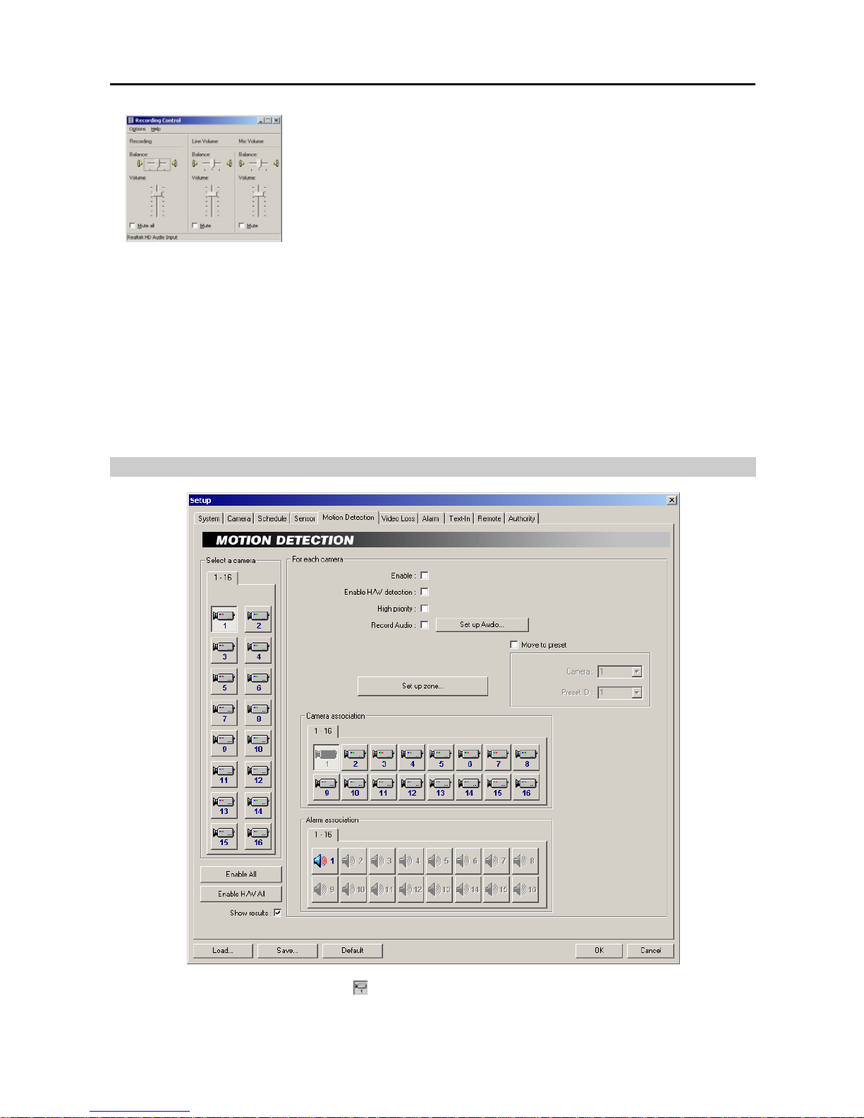
Select a camera: Select a camera icon
to set up.
Enable All: Click the button to enable motion detection for all cameras.
Enable H/W All: Click the button to enable hardware motion detection for all cameras. (PDR16-PC-RT model)
Page 21
Digital Video Recorder
15
NOTE: Using hardware motion detection will increase system performance by decreasing a system load; however,
hardware motion detection might be less sensitive than general motion detection.
Show results: Check the box to display detection results on the monitoring image for all cameras set to enable motion
detection. If you want to use the Show results, the Show OSD option should be selected during the System setup.
Enable: Check the box to enable motion detection for the selected camera.
Enable H/W detection: Check the box to enable hardware motion detection for the selected camera. (PDR16-PC-RT
model)
High priority: Check the box to give high priority to the target camera. The DVR will follow the advanced camera
setup when the target camera detects motion. Refer to the Setting Up Cameras section (p. 9) for configuring
advanced camera setup.
Record Audio: Check the box to record audio when a selected camera detects motion. Click the Set up Audio...
button, and the Recording Control dialog box appears.
Set the audio balance and volume in the Recording column. When checking the
Mute all box or the Mute box in the column of the connected audio input type (Line
or Mic), audio will not be recorded.
NOTE: Make certain you comply with all local and federal laws and regulations
when recording audio.
NOTE: Audio will be recorded while the DVR records video.
NOTE: The DVR provides two types of audio input, Microphone and Line-in.
Microphone is for an unamplified source while Line-in is for an amplified source.
NOTE: The hard disk drive for saving image files must have at least 700MB free space.
NOTE: The recording speed might decrease when the image files from multiple cameras are saved at the same time.
NOTE: Make certain you comply with all local and federal laws and regulations when recording audio.
Move to preset: Check the box to move the target camera to the preset location when a selected camera detects
motion. Select the camera and preset ID from a drop-down list. Preset values can be set individually by the user
who logs in the system.
Set up zone...: Set up the motion detection zone, and the motion detection zone setup window appears.
The setup screen is made up of a grid. First, click the
Draw radio button and select a tool to use from the dropdown list, and then set up the detection zone on the image.
Use the tools as follows:
− Point: Place the cursor on the image and click the left
mouse button. A single box appears where the cursor is.
− Line: This tool can be used to draw irregular shapes.
Place the cursor where you want to start the line. Hold
down the left mouse button and drag the cursor to where
you want the end of the line. Release the mouse button
and a group of boxes appears along the line you drew.
You can draw lines around shapes by repeating this
process.
− Rect (Rectangle): Hold down the left mouse button and
drag the cursor in any direction. A rectangle appears.
Once the rectangle is the size you want, release the mouse
button and the rectangle fills with boxes.
− Fill: When using the fill tool, clicking the mouse will
fill that area of the image with boxes. If a shape has been
drawn with the line tool, clicking inside will fill the area
with boxes. Clicking outside the area will fill the outer
area with boxes. If no shapes have been drawn, the entire
screen will fill with boxes.
NOTE: When you select the Erase, you can use the tools as described above to delete boxes.
Page 22
User’s Manual
16
– Sensitivity: Set the motion detection sensitivity from 1 to 5 (1 to 10 for hardware detection) by holding down and
dragging the pointer.
NOTE: The higher the number, the more sensitive it is.
– Min. size: Set the minimum number of blocks from 1 to 100 (1 to 60 for hardware detection). If you set the Min.
size value to 10, the DVR will only react to the motion when it detects motion (activity) in at least 10 connected
blocks within the selected detection zone. The Min. size should not exceed the selected block numbers for detection.
NOTE: When selecting multiple detection area groups, the minimum number of blocks (Min. size) should not
exceed the block numbers of the smallest detection area.
– Max. size: Set the maximum number of blocks from the preset Min. size value to 1200. If you set the Max. size
value to 100, the DVR will ignore the motion which exceeds the 100 blocks.
– View Result: Check the box to see detection results. You can check that sensitivity and minimum size are set
correctly using this feature. You can save your changes by clicking the OK button. Selecting Cancel exits the
dialog box without saving the changes.
– Camera association: Click the camera icon to associate it with the camera selected during the Select a camera
setup. If motion is detected by one camera, other cameras can be associated with it so that video will also be recorded
from the associated cameras.
– Alarm association: Click the alarm icon to associate it with a selected sensor. The alarm will go off when a
selected camera detects the motion.
Setting Up the Video Loss
NOTE: When any camera loses video (Video Loss) or it detects video again after video loss (Video On), the DVR
considers both Video Loss and Video On as video loss events.
Page 23
Digital Video Recorder
17
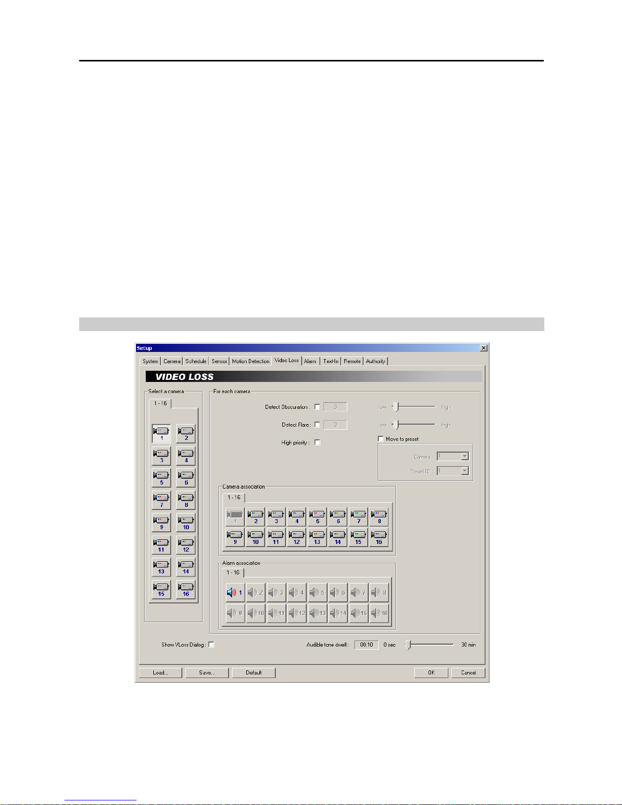
Select a camera: Select a camera icon to set up.
Detect Obscuration: Check the box to use the obscuration detection. And then set the obscuration level from 0% to
50% by holding down and dragging the pointer. The higher the percentage, the more sensitive it is. If the obscuration
detection is selected, the DVR will check the obscuration of the target camera, and consider the obscuration on the
images as video loss.
Detect Flare: Check the box to use the flare detection. And then set the flare level from 0% to 50% by holding
down and dragging the pointer. If the flare detection is selected, the DVR will check the brightness of the target
camera, and consider the flare on the image as video loss.
High priority: Check the box to give high priority to the target camera. The DVR will follow the advanced camera
setup when the target camera detects video loss. Refer to the Setting Up Cameras section (p. 9) for configuring
advanced camera setup.
NOTE: The hard disk drive for saving image files must have at least 700MB free space.
NOTE: The recording speed might decrease when the image files from multiple cameras are saved at the same time.
Move to preset: Check the box to move the target camera to the preset location when a selected camera has lost
video. Select the camera and preset ID from a drop-down list. Preset values can be set individually by the user who
logs in the system.
Camera association: Click the camera icon to associate it with the camera selected during the Select a camera
setup. If video loss is detected by one camera, other cameras can be associated with it so that video will also be
recorded from the associated cameras.
Alarm association: Click the alarm icon to associate it with a selected sensor. The alarm will go off when an associated
sensor is activated.
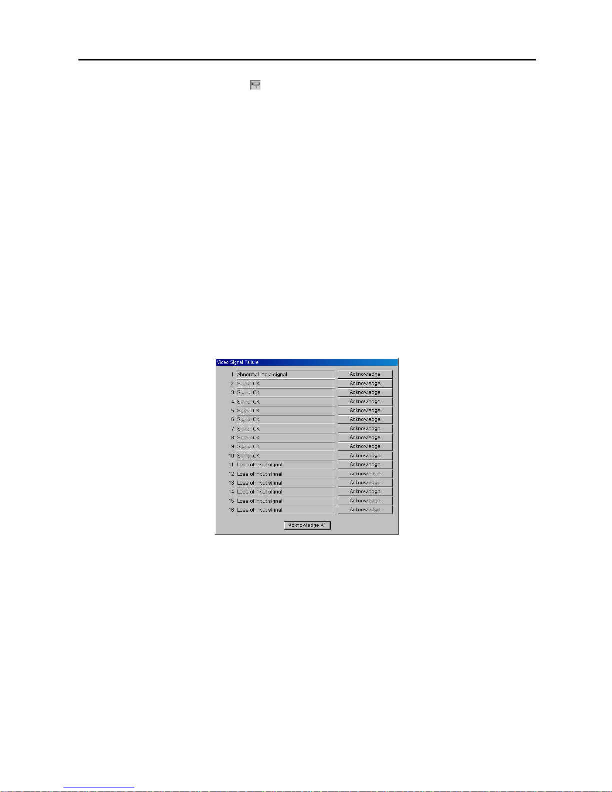
Show video loss dialog: Check the box if you want to show the following Video Signal Failure dialog box on the
screen when the video loss is detected. Click the Acknowledge or Acknowledge All button to close the dialog box.
Audible tone dwell: Set the dwell time of alarm output. The alarm output will be activated during the preset dwell
time when the video loss is detected.
NOTE: The alarm output can be reset during alarm activation only by clicking the Acknowledge or Acknowledge
All button in the Video Signal Failure dialog box.
Page 24
User’s Manual
18
Setting Up the Alarm
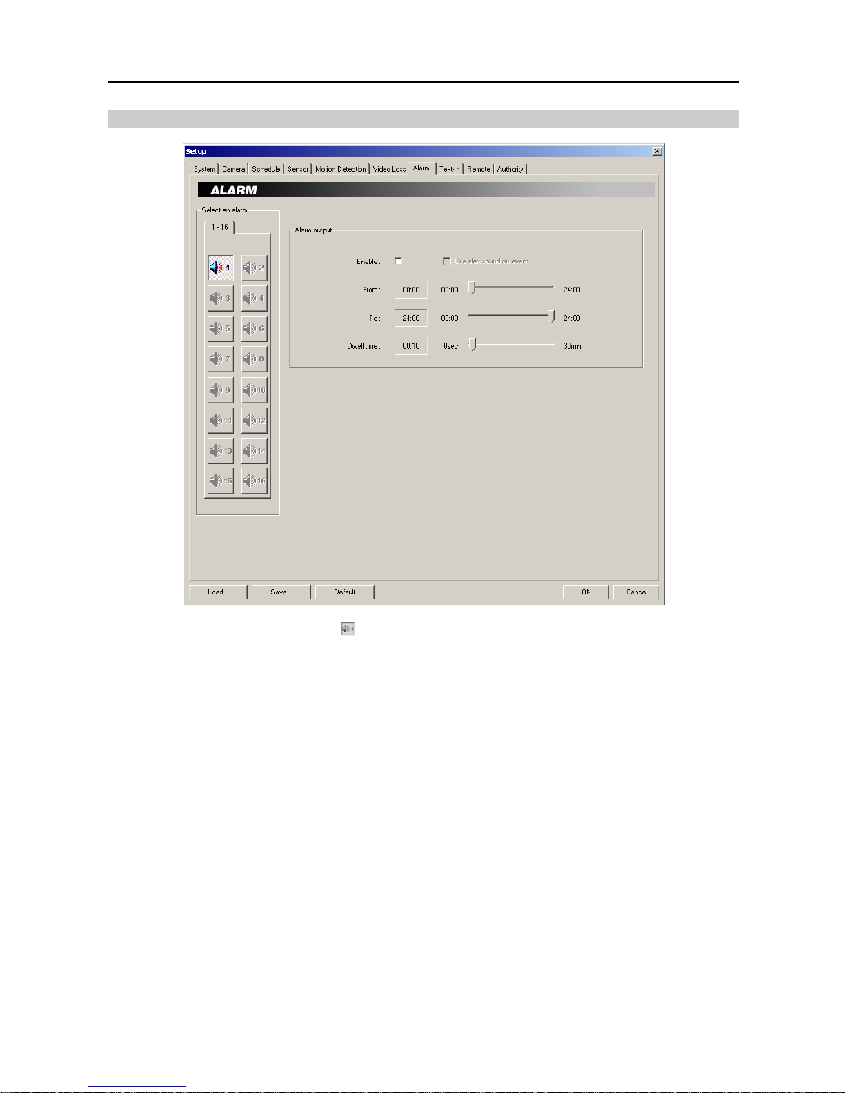
Select an alarm: Select an alarm icon
to set up.
Enable: Check the box to enable the selected alarm. When selecting Use alert sound on event, the DVR will
play alert sound through the attached speaker during alarm output. You can set up the DVR to play different alert
sounds for each type of event. Create sound files (.wav) for each type of event under program installation folder and
name the sound files: sensor.wav for alarm-in, motion.wav for motion detection and vloss.wav for video loss.
From / To: Set the beginning and ending time (00:00 to 24:00) of alarm activation by holding down and dragging
the pointer.
NOTE: In cases where the From hour is later than the To hour, the alarm will be activated at the From time of the
current date until next day's To time. If you set To: 08:00 and From: 18:00, this means the alarm will be active over
night from 6:00 p.m. until 8:00 a.m. the following day.
Dwell time: Set the alarm output duration (0 seconds to 30 minutes) by holding down and dragging the pointer.
Page 25
Digital Video Recorder
19
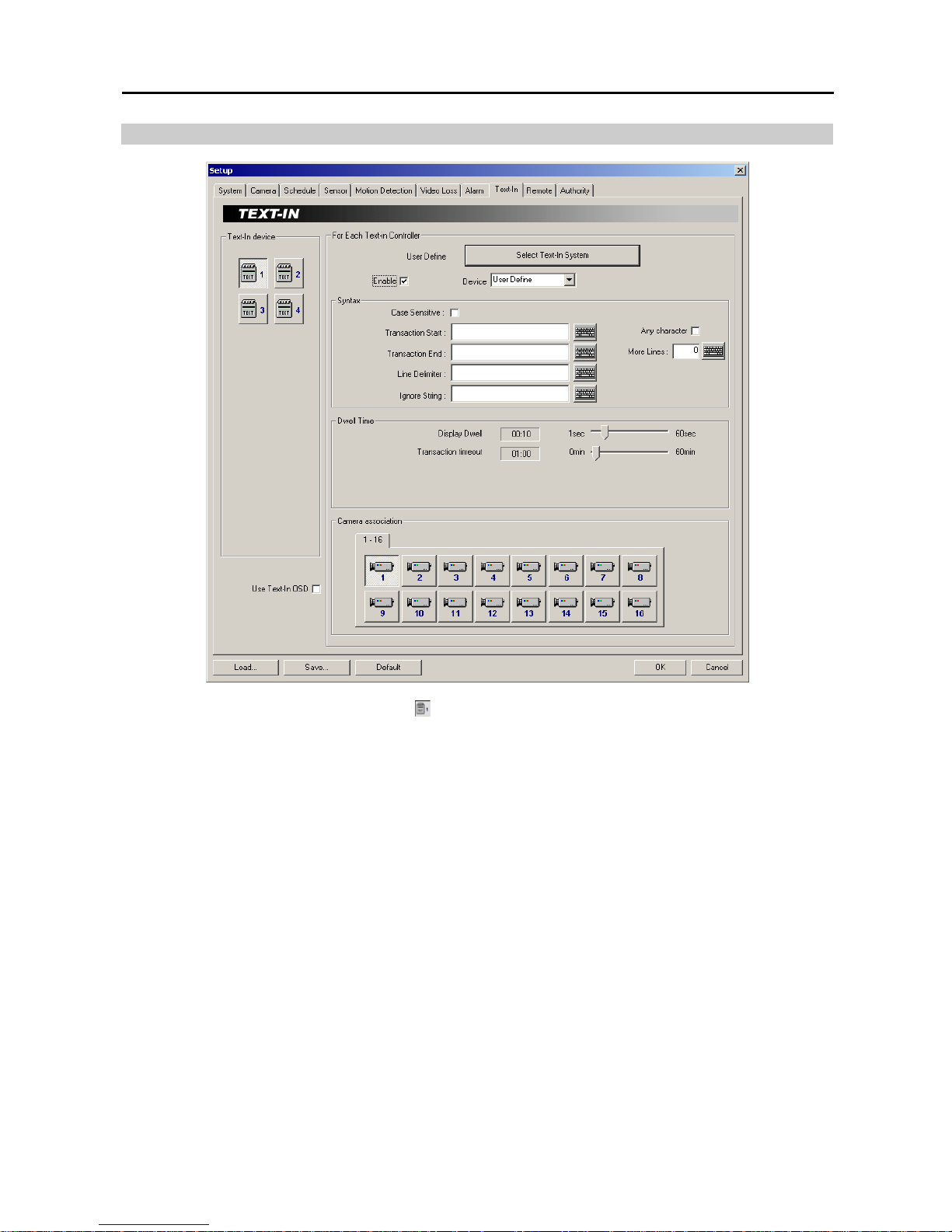
Setting Up the Text-In
Text-In device: Select a text-in device icon
to set up.
NOTE: Up to 4 text-in channels are available using the WIBU key.
Use Text-In OSD: Check the box if you want to display text-in information on the image. The box will be activated
when a camera is associated with the text-in device.
Enable: Check the box to enable to use the selected text input device.
Select Text-In System: Set up the text-in device. Select the model of installed text-in system from the Text-In
Model list, and the COM port to use from the drop-down list. Click the Set up port… button to display the Set up
COM Port dialog box. Set the Baud rate from 300 to 256,000, select the Parity from None, Even or Odd parity,
select the Data bit from 7 bit or 8 bit format, select the Stop bit from 1 bit or 2 bits from the drop-down list. You
can save your changes by clicking the OK button. Selecting Cancel exits the dialog box without saving the changes.
Device: Select the type of text-in device to use.
NOTE: Each type of text-in device (User Define, GnomeII and so on) has different setup options which can be
defined by the user.
NOTE: When using the RS232 port, select COM 1 from the COM Port drop-down list. When using the RS485
port, select the given COM Port number. To check the given COM port number, please refer to the installed card
information displayed on the System Info. dialog box by clicking the System Info. button.
NOTE: The hard disk drive for saving image files must have at least 700MB free space.
NOTE: The recording speed might decrease when the image files from multiple cameras are saved at the same time.
Syntax
– Case Sensitive: Check the box to distinguish between capital letters and small letters from text-in data.
– Transaction Start: Enter the character string to be considered as transaction start. If the Any character box is
checked, preset any character will be considered as transaction start.
Page 26
User’s Manual
20
– Transaction End: Enter the character string to be considered as transaction end.
NOTE: Entering multiple keywords for Transaction Start/End are supported. Use a semi-colon (;) to delimit each
keyword. When the semi-colon is included in Transaction Start/End itself, use a double semi-colon (;;).
– More Lines: Set the line count after preset character string for transaction end. The DVR will include preset line
count in one transaction.
– Line Delimiter: Enter the character string that divides each text-in line.
– Ignore String: Enter the character string. The DVR will ignore the text-in line including the string which is set
in this field.
Dwell Time
– Display Dwell: Set the dwell time to display the text-in information by holding down and dragging the pointer.
– Transaction Timeout: Set the duration to wait for a new text input. The DVR will consider the transaction is
ended if there is no text input during preset timeout after the last text input.
Camera association: Click the camera icon to be associated with a selected text-in device. Multiple cameras can
be selected. The text-in information will be displayed on the screen when the associated camera is displayed in the
single-screen mode.
Setting Up the Remote Access
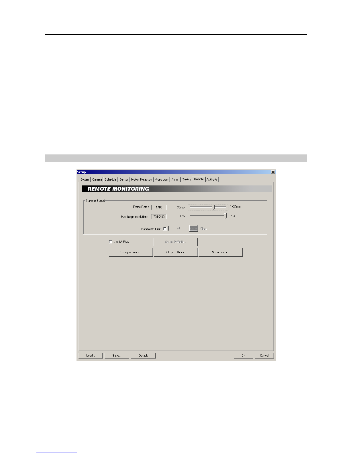
Transmit speed: Set the Frame Rate and Max image resolution by holding down and dragging the pointer. Check
the Bandwidth Limit box if you want to control the network bandwidth, and then enter the bandwidth limit (kbps)
using either actual keyboard or the virtual keyboard.
NOTE: The transmit speed is the number of images that can be transmitted for each camera. Therefore the lower
the value, the more images are transferred during the same time. For example, when using one camera, the value
30 means one image per 30 seconds will be transmitted. 1 means one image per second, and 1/30 means that
30 images per second.
Page 27
Digital Video Recorder
21
NOTE: For example, if the available maximum recording speed is 480 images per second and you have 16 cameras,
the transmit speed for each of the 16 camera can be maximum 1/30 sec (30 images per second). Even if you set
the transmit speed settings to more than 480 images per second for the 16 cameras, the DVR cannot transmit more
than 480 images per second. When this happens, the cameras will share the 480 images per second capacity.
Refer to Appendix 11 — Specifications for the available maximum recording speed of each model.
NOTE: If the VGA card of a BASE system does not support the overlay function, the transmit speed can slow down
somewhat.
NOTE: The DVR will convert the image resolution according to setting values of Max image resolution when
transmitting the image with the higher resolution than preset resolution. If you set 320x240 (352x240 (352x288
PAL) for PDR16-PC-RT model) for the Max image resolution, the image with 640x480 (704x480 (704x576 PAL)
for PDR16-PC-RT model) resolution will be converted to the one with 320x240 (352x240 (352x288 PAL) for
PDR16-PC-RT model) before transmitting to the remote site.
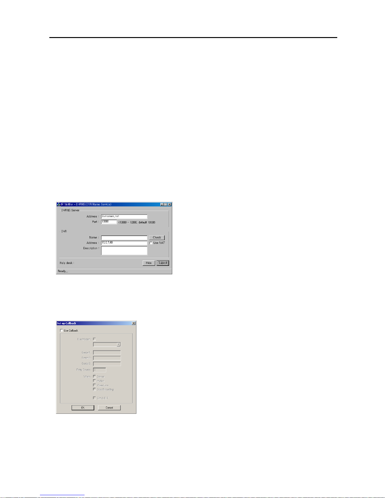
Use DVRNS: Check the box to use DVRNS (DVR Name Service) server. Click the Set up DVRNS… button
displays the IP Notifier – DVRNS (DVR Name Service) dialog box allowing you to set details about DVRNS.
NOTE: The DVRNS (DVR Name Service) allows you to connect to the DVR from remote sites using either the
dynamic IP addresses or the domain name. For the DVRNS feature to work properly, the DVR should be registered
on the DVRNS server, and the DVRNS server settings should match the settings registered on the DVRNS server.
Any changes on the DVRNS server might cause improper operation.
NOTE: The DVRNS registration is limited to only one DVRNS server. The DVR cannot be registered to multiple
DVRNS servers.
− DVRNS Server: Enter the IP address (or domain name) and
port number of the DVRNS server.
− DVR: Enter the unit name to be registered on the DVRNS server
and enter the DVR Description. Clicking the Check button next
to the Name box allows you to check if the name you entered
can be used. The Address displays the IP address of the DVR.
When using the NAT (Network Address Translation) device,
check the Use NAT box.
− Help desk: Displays the information registered on the DVRNS
server.
You can save your changes, register the DVR information on the DVRNS server by clicking the Change button,
and hide the IP Notifier – DVRNS (DVR Name Service) dialog box by clicking the Hide button.
Set up network...: Set up the network. Refer to Appendix 3 — Network Setup for details.
Set up Callback…: Set up the callback function. The DVR can be set up to notify the target server running the
SmartBase when certain events occur.
− Use Callback: Check the box to enable the callback function.
− Center: Enter the IP address of each server. A maximum of three servers
can be set.
− Retry Counts: Enter the number of times you would like the DVR to try
contacting the server if the connection fails.
− When: Select the target event. The DVR will call when the selected events
occur. Multiple selections are available. You can save your changes by clicking
the OK button. Selecting Cancel exits the Set up Callback dialog box without
saving the changes.
NOTE: Callback messages will be displayed on the system status window
of the target server. They include event type, event detection time, and system
location entered during the System setup.
Page 28
User’s Manual
22
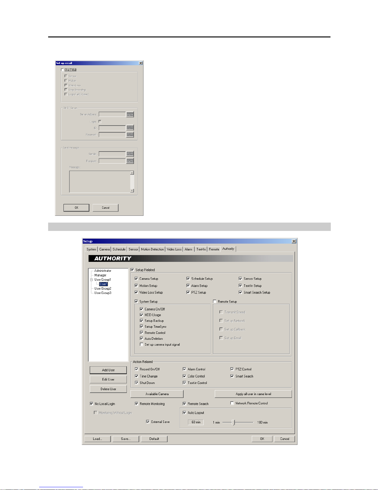
Set up Email…: Set up the e-mail notification. Each event can be set individually for e-mail notification.
− Use Email: Check the box to enable e-mail notification function.
− SMTP Server: Enter an SMTP server IP address. Check the Login box if
you want to connect to the SMTP server that requires login procedure, and
enter the IP and password for login.
− Email message: Click the text field beside Sender. And then enter a
sender’s e-mail address. Click the text field beside Recipient, and enter a
recipient’s e-mail address. Click the text field under Message, and type
in the e-mail message.
NOTE: If you want to send the e-mail to multiple recipients, enter a “,” or
“;” between e-mail addresses in the Recipient box.
Setting Up the Authority
Page 29
Digital Video Recorder
23
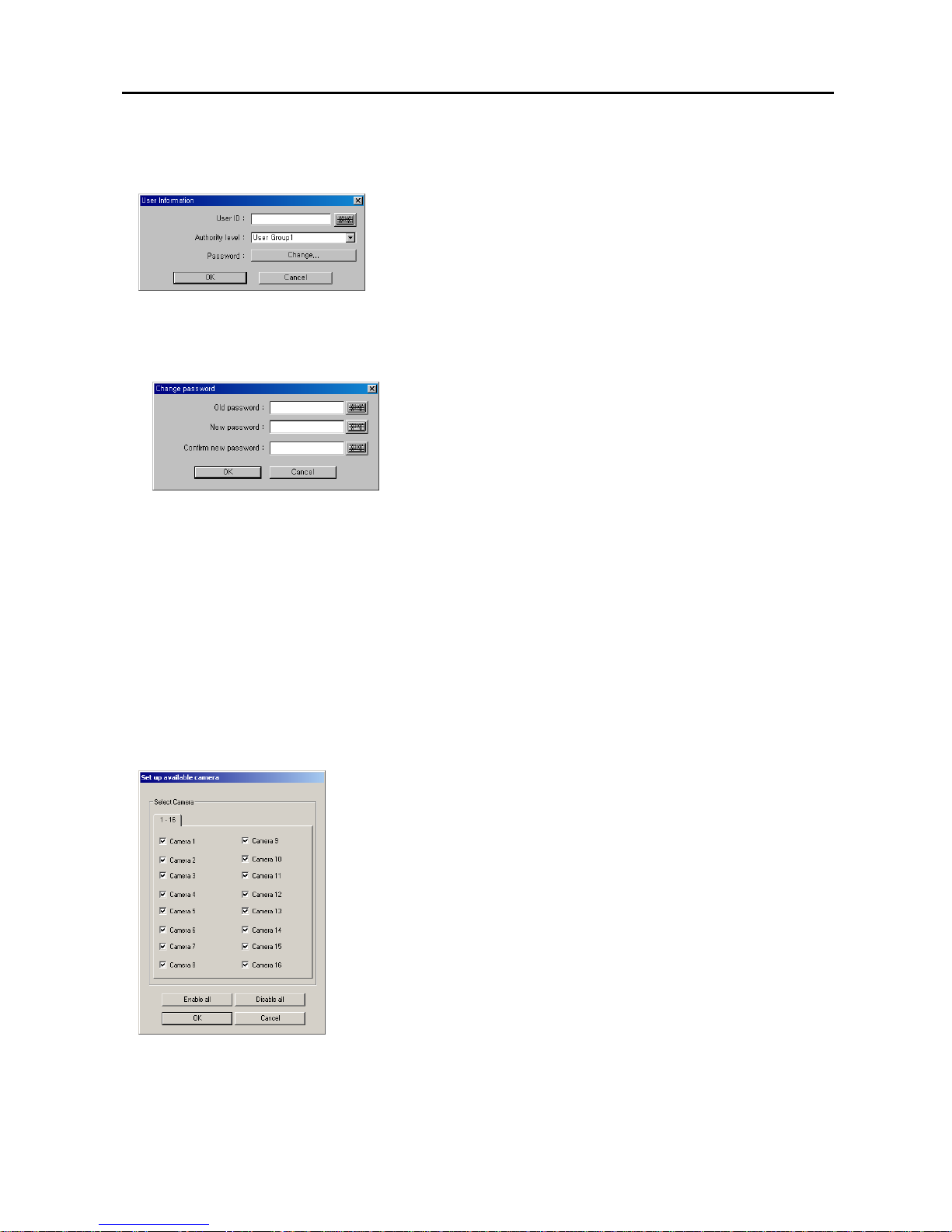
Add User: Click the button and the User Information dialog box appears. Set up the user information to register
a new user.
NOTE: Up to 256 users can be registered.
− User ID: Enter the user ID using either the actual keyboard or the virtual
keyboard.
− Authority level: Select the authority level from a drop-down list: User
Group (1-3), Manager, or Administrator.
NOTE: Only the administrator level user can change the Remote and
Authority setup
.
NOTE: The authority setup of the Administrator cannot be edited.
– Change...: Click the button and the Change password dialog box appears. Set up the password for a newly
registered user.
Click the text field beside New password and Confirm new password,
and enter the password using either the actual keyboard or the virtual
keyboard. The Old password may not be used when entering a password
for a newly registered user. After you have set up the password, you can
save your settings by clicking the OK button. Selecting Cancel exits the
dialog box without saving the changes.
NOTE: Up to eight characters may be used for a password.
NOTE: The password will not be saved when New password and Confirm new password do not match.
After you have set up the user information, you can save your settings by clicking the OK button. Selecting Cancel
exits the dialog box without saving the changes.
Edit User: Click the button to edit the established user information. If you want to delete the user, click the Delete
User button after selecting the user to delete in the list.
NOTE: The password will not be changed when the Old password does not match, or the New password and Confirm
new password do not match.
Setup Related / Action Related: Select a registered user in the list, and check the desirable option boxes to set
the user’s authorization.
NOTE: Only the administrator level user can edit the user’s information and their authority setup.
Available Camera: Click the button if you want to assign the camera number individually to each user.
Check the box beside the camera number to enable the user to monitor and review
that camera image. Clicking the Enable all or Disable all button enables or
disables all the cameras to the target user.
Apply all user in same level: Click the button if you want to apply the current authority settings to all users in the
same authority level.
No local login: Check the box if you do not want the login procedure. Otherwise, the User Login dialog box will
appear when clicking any function button and ask entering User ID and Password. Check the Monitoring without
login box if you want to monitor the image even while you are logged out.
Page 30

User’s Manual
24
Remote Monitoring: Select a registered user in the list and check the box if you want to allow the user to access
to the POST system from the BASE system.
Remote Search: Select a registered user in the list and check the box if you want to allow the user to play back
video recorded on the POST system in the BASE system.
Network Remote Control: Select a registered user in the list and check the box if you want to allow the user to
control the DVR remotely via network connections by using the network keyboard.
Auto Logout: Check the box and set the logout dwell time (from 1 to 180 minutes) if you want to log out the DVR
automatically when there is no keyboard or mouse operation during the preset dwell time.
External Save: Select a registered user in the list and check the box if you want to allow the user to save recorded
video as a bitmap, AVI or executable file or to burn a CD/DVD.
Page 31
Digital Video Recorder
25
Chapter 3 — SmartSearch
OVERVIEW
SmartSearch is a powerful tool for SmartGuard. It features playback and search functions for recorded data and consists
of Playback Screen, Timetable, Status Window and Utility Buttons. Each area displays or controls recorded information.
Click the Search button in the SmartGuard mode to get into the SmartSearch mode. To return to the SmartGuard mode,
click the Close button on the remote control in the SmartSearch mode.
NOTE: The playback speed can be slow when the DVR is recording images at its maximum recording speed). For
the normal playback speed, stop recording by clicking the Rec button in the SmartGuard mode.
FEATURES
Searches by camera and time
Provides recording status table
Various search functions
Zoom in/out function
Image enhancement functions
Print function
Remote playback function
Bookmark function
Saves to AVI file
Audio playback
MAIN GUI
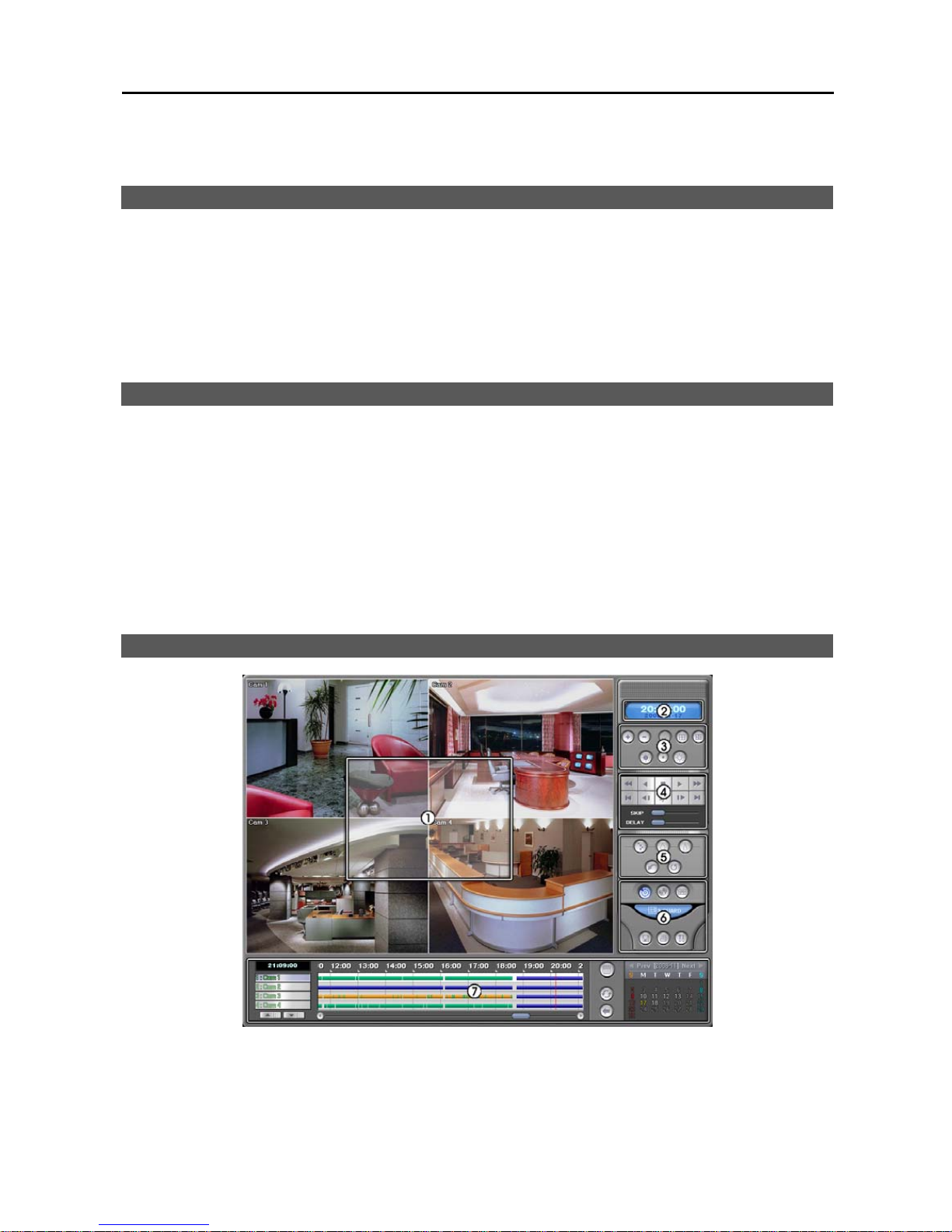
① Playback Screen: Displays the current playback image.
② Clock: Displays the date and time of the current playback image.
③ Image Adjustment Buttons: Click to change the brightness of the current image or enlarges or shrinks the current
image. Refer to the Image Adjustment section (p. 26) for details.
Page 32
User’s Manual
26
④ Playback Control: Click to display the playback control buttons. You can search and play back recorded video.
Refer to the Playback Control Buttons section (p. 26) for details.
⑤ Image Processing Buttons: Click the desired button to enhance played back images. Refer to the Image Processing
Buttons section (p. 27) for details.
⑥ Utility Buttons: See the Utility Buttons section (p. 27) for details.
⑦ Timetable: The timetable window consists of a record timetable, camera label and a calendar/bookmark. You will
see the bank file recording information. Various functions of the timetable window enable fast searches. Refer to
the Search and Playback of Recorded Video – Time-Lapse Search section (p. 29) for details of searching video
by using the timetable.
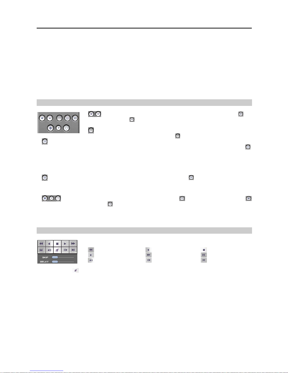
Image Adjustment
(Zoom): Enlarges or shrinks the current image. To enlarge the image, click . To
shrink the image, click
. This button works only in the single-screen mode. You can also
enlarge or shrink the image by rolling the mouse wheel on the image.
(Series): Displays images from one camera image by image. For series display, select a
camera button and a desired screen mode, and click
. Then, click any playback-related button.
(Screen Division): Every time this icon is clicked, the screen mode switches (single-screen → quad → 3x3 → 4x4).
For multi-screen playback, select a camera button from the timetable, and select a desired screen mode by clicking
.
Then click any playback-related button.
NOTE: 1-4, 5-8, 9-12, or 13-16 camera groups are displayed on the screen in quad mode, and 1-9 or 10-16 camera
groups in 3x3 mode. The user can select which camera group is displayed by clicking any camera button in a group
from the timetable.
(Full Screen): Display the recorded images in full-screen mode by clicking
during playback. To exit from
full-screen mode, click the left mouse button anywhere on the screen.
NOTE: Full-screen display cannot be supported if the VGA card of the system does not support the overlay function.
(Brightness): Changes the brightness of the current image. Click to make the image brighter, click
to make the image darker and click
to set the brightness to the default setting.
NOTE: Make certain that the cameras and monitor are adjusted properly before recording because this adjustment
should not be used to correct improperly recorded video.
Playback Control Buttons
Playback Control Buttons: Controls playback of recorded video.
Fast Backward Play Backward Play Stop
Play Fast Forward Play Go to First Image
Rewind One Image Forward One Image Go to Last Image
Search Button ( ): Searches for images according to the user-defined search condition (Single-screen mode only).
Refer to the Condition Search section (p. 27) for details.
SKIP: Sets the image number to be skipped by holding down and dragging the pointer while the DVR is in the Fast
Forward or Fast Backward playback mode.
DELAY: Sets the delay time for each image playback by holding down and dragging the pointer while the DVR is
in the Fast Forward or Fast Backward playback mode.
NOTE: Pressing the Fast Forward Play button and Fast Reverse Play button toggles the 2x, 4x and 8x forward
and backward speed.
NOTE: In the full screen mode, you can control playback of recorded video by using the Floating Playback Panel
window displayed when clicking the right mouse button on the screen. The window can be moved at any place
on the screen by dragging the mouse.
Page 33
Digital Video Recorder
27
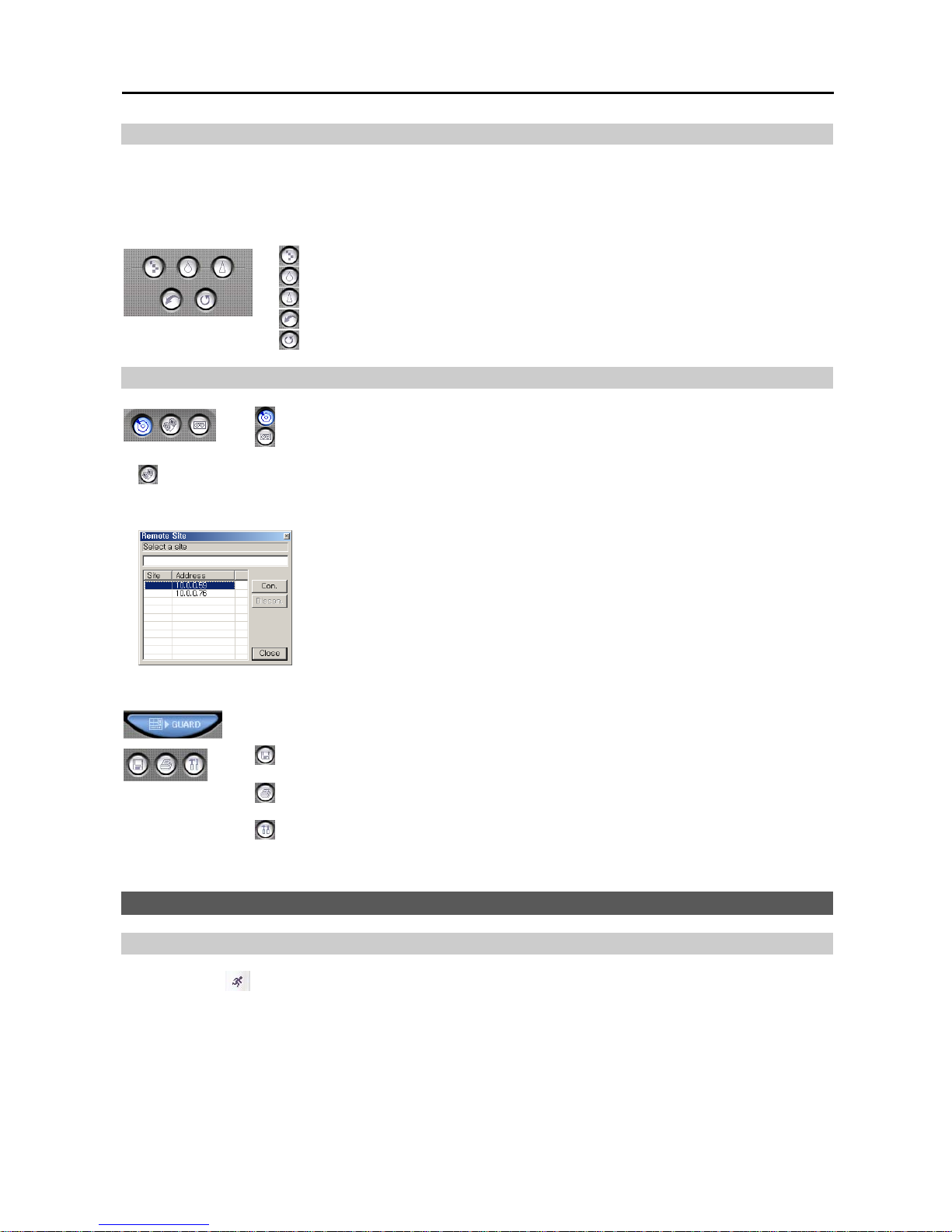
Image Processing Buttons
NOTE: The recorded video will be displayed on the playback window with 640x480 (704x480 (704x576 PAL) for
PDR16-PC-RT model) as default even though their resolution is 160x120 (176x120 (176x144 PAL) for PDR16-PC-RT
model) or 320x240 (352x240 (352x288 PAL) for PDR16-PC-RT model). At this time, the DVR will interpolate the
enlarged video automatically.
(Interpolation): Reduce the alias effect that occurs when using the zoom function.
(Blur): Blurs the image to reduce noise.
(Sharp): Sharpens an image.
(Undo): Cancels the last image processing operation.
(Revert): Cancels the image processing operation and reloads the original image.
Utility Buttons
(Local): Click the button to load recorded data from the local hard disk drive.
(Backup): Click the button to load backup data from the extra backup device (e.g. CD-RW,
DVD RW, USB hard disk drive).
(Remote): Click the button to load recorded data from the remote DVR via LAN. The following Remote Site
dialog box appears, and the remote site(s) you registered for remote playback is (are) displayed in the list box. Refer
to the Network section (p. 37) for details of registering remote sites for remote playback.
− Connecting to a remote site…: Click the site where you want to connect in the list box,
and then click the Con. button. You can also connect to a remote site quickly by double
clicking the site where you want to connect in the list box or by entering the site
address in the text field located under Select a site and pressing the enter key.
− Disconnecting a remote site…: Click the site where you want to disconnect in the list
box, and then click the Discon. button.
NOTE: If you want to arrange the site list in the descending orders, click the
Address headings on the list box.
NOTE: The DVR can only view recorded, not live video on another DVR.
Accessing SmartGuard: Click the GUARD button to quit SmartSearch and return to SmartGuard
.
(External Save): Click the button to save recorded video. Refer to the Saving of Recorded
Video section (p. 30) for details.
(Print): Click the button to print the current image. Refer to the Printing Current Image
section (p. 35) for details.
(Setup): Click the button to set up the SmartSearch. Refer to the SmartSearch Environment
Setup section (p. 36) for details.
SEARCH AND PLAYBACK OF RECORDED VIDEO
Condition Search
Click the Search
button on the Playback Control buttons. The following setup screen appears. Designate the find
range and set up the search condition in the Motion Detection, Event Detection or Text-In tab.
Page 34
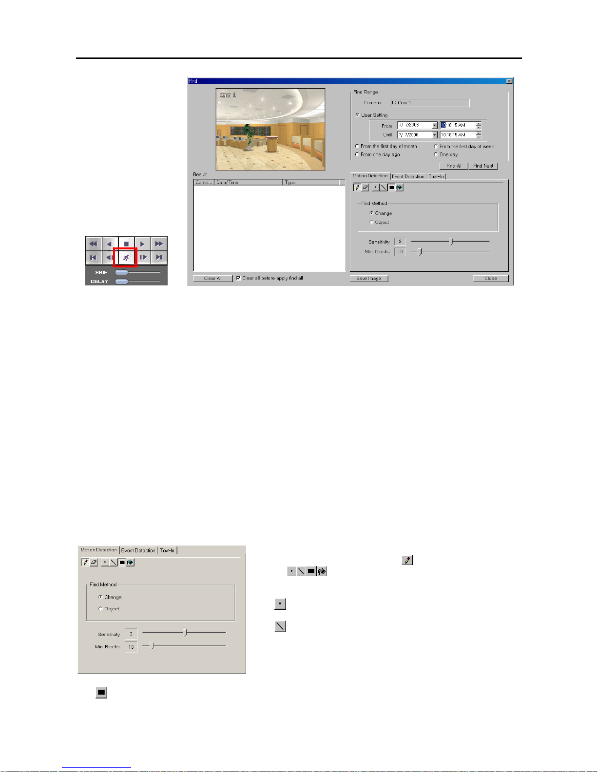
User’s Manual
28
Find Range: Set the find parameters.
– User Setting: Finds event logs between user-defined periods. Set the desired find beginning and ending date/
time in the From and Until boxes.
– From the first day of month: Finds event logs from the first day of this month.
– From the first day of week: Finds event logs from the first day of this week.
– From one day ago: Finds event logs from one day ago.
– One day: Finds event logs for one day.
Motion Detection / Event Detection / Text-In: Set up the search condition. Refer to the Motion Detection, Event
Detection and Text-In sections for details.
Save Image: Saves the current image of the result as a bitmap or JPEG file to the local hard disk drive or floppy disk.
Find All: Finds all event results within established find conditions and then display them in the Result list box.
Find Next: Finds one event at a time.
Result: Displays the search result.
– Video Screen: Displays the searched video at the top left in the setup screen. The image of the result can be displayed
by double clicking the target event in the Result list. You can play back searched video on the SmartSearch playback
screen when you exit the setup screen by clicking the Close button.
– Clear All: Removes all entries listed in the box.
– Clear all before apply find all: Check the box if you want to remove the results before applying Find All.
Save Config: Saves the current text-in related settings when selecting the Text-In tab.
Load Config: Loads the saved text-in related settings when selecting the Text-In tab.
Motion Detection: Select the Motion Detection tab to search for motion detected video.
Motion Detection Zone: Set up the detection zone using the area setup
icons. First, select the Draw mode
and then select one of four
tools
by clicking the target icon. Move the cursor on the
image of the selected camera displayed in a small window, and set
up the detection area using the selected tool. Use the tools as follows:
– (Point): Place the cursor on the image and click the left mouse
button. A single box appears where the cursor is.
– (Line): This tool can be used to draw irregular shapes. Place
the cursor where you want to start the line. Hold down the left mouse
button and drag the cursor to where you want the end of the line.
Release the mouse button and a group of boxes appears along the
line you drew. You can draw lines around shapes by repeating this
process.
–
(Rectangle): Hold down the left mouse button and drag the cursor in any direction. A rectangle appears. Once
the rectangle is the size you want, release the mouse button and the rectangle fills with boxes.
Page 35
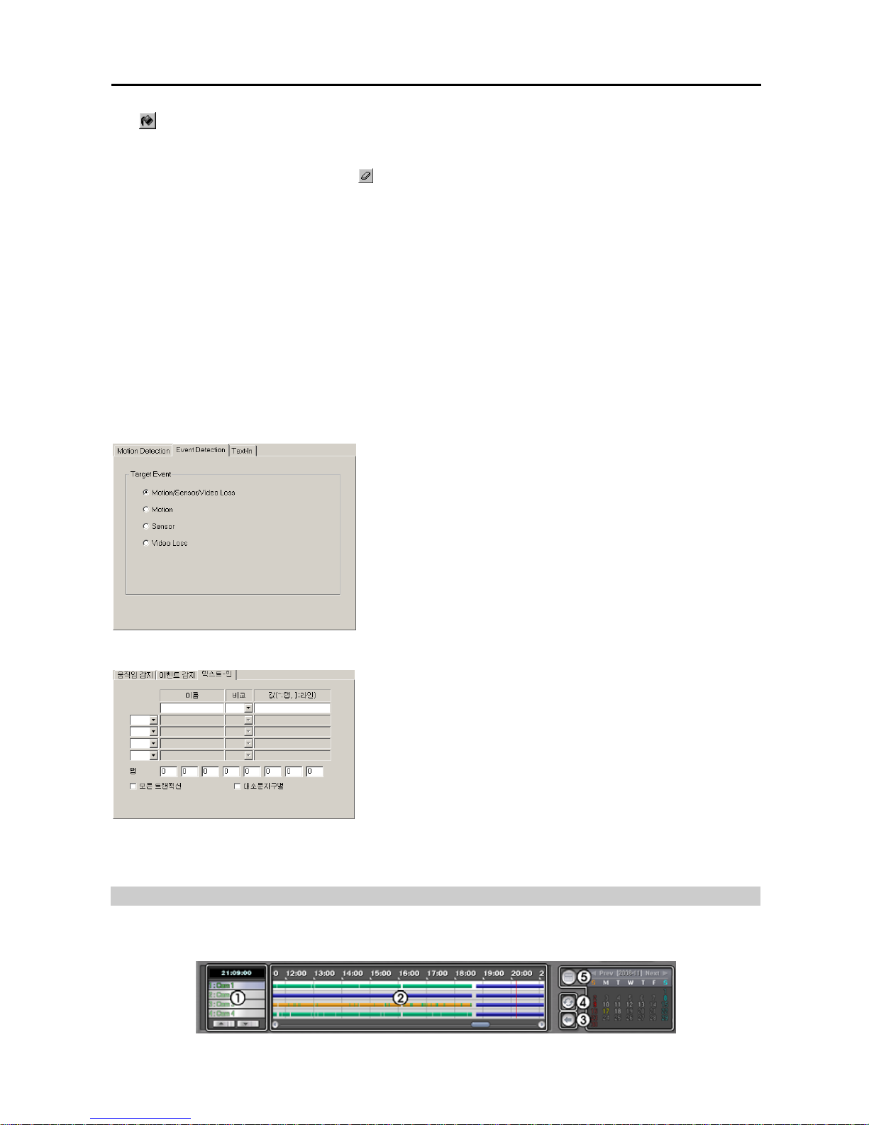
Digital Video Recorder
29
– (Fill): When using the fill tool, clicking the mouse will fill that area of the image with boxes. If a shape has
been drawn with the line tool, clicking inside will fill the area with boxes. Clicking outside the area will fill the
outer area with boxes. If no shapes have been drawn, the entire screen will fill with boxes.
NOTE: When you select the Erase mode , you can use the tools as described above to delete boxes.
Find Method: Select either Change or Object.
– Change: Detects changes at the user-defined motion detection zone between two consecutive images which are
usually motion. For example, if you want to detect if anyone passes through a door, you can draw a Change
detection around the door. The system will search through recorded data for any motion in the doorway.
– Object: Detects changes at the user-defined motion detection zone as compared with the image displayed currently
on the Video Screen when an object is removed or moved in an area where there is normally motion. For example,
you can draw a box around a painting hanging in a hallway. People walking by the painting will not be listed as
an event. However, if the painting is removed, this will be listed as an event.
Sensitivity: Set the sensitivity of the motion detection (1 to 5) by holding down and dragging the pointer.
Min. Blocks: S et the minimum number of blocks (1 to 100).
NOTE: The number of minimum blocks should be set less than the number of blocks within the motion detection
zone. If the user draws a rectangle with 25 blocks and sets the minimum blocks to 30, nothing will be detected
even though there is motion.
Event Detection: Select the Event Detection tab to search for event detected video.
Target Event: Select a desired event.
Text-In: Select the Text-In tab to search for text-in event detected video.
Name: Enter the text to find.
Comp: Enter the comparison operator.
Value: Enter the comparison value.
NOTE: The tab and line can be used for more specific search of the
text-in data. Use a symbol ‘^’ indicating the location of each individual
category, and ‘]’ indicating the line where the category is located. Refer
to Appendix 6 — Text-In Query for details.
Tab size: Enter the tab size. Up to eight tabs can be set.
All Transaction: Check this box to find all transaction results within
established find conditions.
Case Sensitive: Check this box to distinguish between capital letter
and small letters entered in the Name box.
Time-Lapse Search
The timetable window consists of a record timetable, camera label and a calendar/bookmark. You will see the bank
file recording information. Various functions of the timetable window enable fast searches.
Page 36
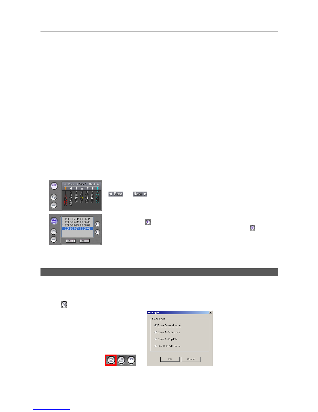
User’s Manual
30
① Camera Label Buttons: Shows camera information. You can change the current playback camera by clicking
the camera label button. The camera label buttons that do not have recorded data cannot be selected. Only four
camera labels are shown at a time. Use the up and down arrows to scroll through the list of cameras. The numbers
on the left side of the panel displays eight camera groups. When you check the Arrange cameras on the screen
manually box during the Environment Setup setting, you can arrange cameras manually at the desired location
of the playback screen. Click the camera button and click the button again, and the camera label’s color changes
to red. Click the screen at the desired location of the playback screen, and the playback image or the camera number
of the selected camera is displayed on the selected screen. You can arrange cameras differently depending on the
screen mode, and video of the selected camera is displayed on the screen in the single screen mode.
② Recording Status Bar: Shows recorded information on the recording status bar. You can search specific video
by clicking the mouse on the desired segment or scroll by moving the scroll key from left to right. The color of
the bar indicates different types of recording: Yellow for Pre-event, Cyan for Motion Detection, Red for Sensor,
Grey for Text-in, and Blue for Time-lapse. Every clicking the right mouse button on the timetable zooms the record
timetable in with three levels; one time (hour based time interval) in the first level, four times (30 minute based) in
the second level, and eight times (10 minute based) in the third level.
③ Refresh: Reloads recorded data from the local hard disk drive.
④ Go To: Goes to the specific dates and times directly. Select a date from the drop-down list, and set the time using
the arrow buttons. If you click the OK button after setting the conditions, the image meeting the established conditions
will be displayed on the playback screen. Selecting Cancel cancels the Go To operation and exits the dialog box
without saving the changes.
⑤ Calendar / Bookmark: Goes to the specific dates and times by using the button.
Select recorded data from the calendar. The calendar provides access to single day
recorded data. Click the date you want to search. Scroll through the months by clicking
and . Clicking the button again goes to the bookmark.
You can review the specific image fast and easily by adding bookmarks for recorded
images. Click the
button to bookmark the currently displayed image. If you want
to delete the bookmark, select the target information and then click the
button. A
bookmark lists the camera number, date and time, and bookmark description. The
bookmark description will be shown automatically when the mouse cursor is not moving
on a bookmark data for a while. Clicking the button again goes to the calendar.
NOTE: When adding bookmarks on the BASE system, the bookmarks are saved separately for each remote site.
SAVING OF RECORDED VIDEO
NOTE: The user can save recorded video when the user has an authority with External Save. The External Save
option should be selected during the SmartGuard – Authority setup. Refer to Chapter 2 — SmartGuard, Setting
Up the Authority for details.
Click the (External Save) button. The Save Type screen appears.
Page 37
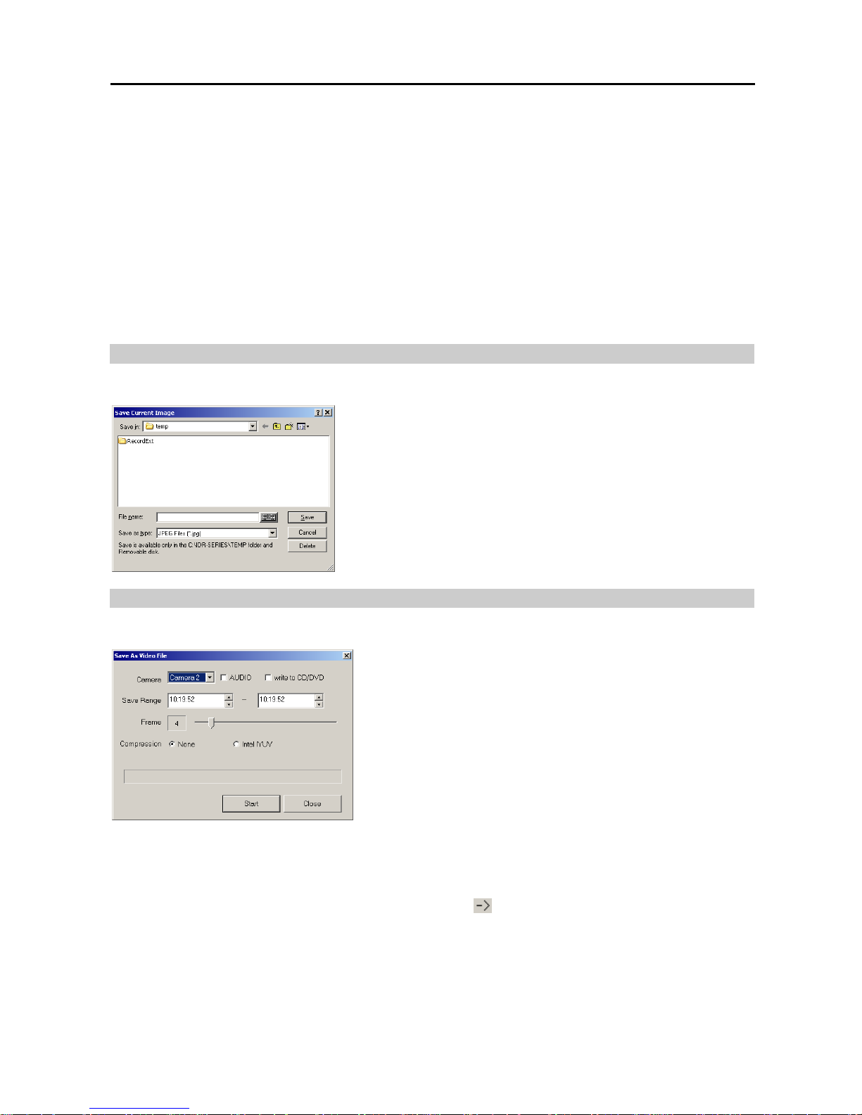
Digital Video Recorder
31
Save Current Image: Saves the current image as a bitmap or JPEG file to the local hard disk drive or floppy disk.
Refer to the Save Current Image section (p. 31) for details.
Save As Video File: Saves any video clip as an AVI file. Refer to the Save As Video File section (p. 31) for details.
Save As Clip File: Saves any video clip as an “.exe” file. Refer to the Save As Clip File section (p. 32) for details.
Run CD/DVD Burner: Saves the recorded data on the CD or DVD drive using the CD/DVD burning program.
Refer to the Run CD/DVD Burner section (p. 32) for details.
NOTE: When you save the current image as a bitmap file (*.bmp file format only) the watermark will be included
on the image, so you can check whether the saved image has been forged using the SmartWatermark (watermark
viewer program).
NOTE: Starting to burn a CD/DVD might interrupt DVR recording.
NOTE: The image and video clip can be saved only under the “C:\IDR-Series\temp” directory, on the removable
disk including floppy disk, CD-RW and DVD RW, or on the hard disk drive with no IBank was created such as external
hard disk drives.
Save Current Image
Click the Save Current Image radio button in the Save Type dialog box, and click the OK button.
Save in: Select the save location from the drop-down list.
File name: Enter the file name using either the actual keyboard or the
virtual keyboard.
Save as type: Select the file format from the drop-down list. The available
formats are bitmap and JPEG files.
Click the Save button to save the current image. Selecting Cancel cancels
the saving operation and closes the dialog box without saving the settings.
NOTE: If you want to delete the file or folder, select the target file or folder
then click the Delete button. You can delete the file or folder only saved
under the “C:\IDR-Series\temp” directory.
Save As Video File
Click the Save As Video File radio button in the Save Type dialog box, and click the OK button.
Camera: Select the camera number to save from the drop-down list.
AUDIO: Check the box to save audio with video.
Write to CD/DVD: Check the box if you want to save the video clip
on the CD or DVD drive directly.
Save Range: Set the range using the arrow buttons.
Frame: Set the frame rate by holding down and dragging the pointer.
You can set the frame from 1 to 30. When the AUDIO box is checked,
you cannot set the frame rate. It will be fixed at 30 frames in order
to synchronize the video and audio.
Compression: Select either None or Intel IYUV. Only Intel IYUV
is supported for compression. When None is selected, the file size
may be large but the image quality will be good.
Click the Start button to display the Save As dialog box. Designate a folder path and enter a file name. Selecting
Save saves video according to the settings. Selecting Close cancels the saving operation and closes the dialog box.
NOTE: When the write to CD/DVD box is checked, you need to select the CD or DVD recorder to use, and select
the folder name to save on the CD or DVD drive by clicking the
button. You can designate the folder path by
entering “/” between the directory name and file name. For example, if you enter "abank/test", a directory named
“abank” with an ‘.avi’ file named “test.avi” will be created.
NOTE: Writing on the DVD is available only on the Windows XP embedded version over 2.0.
NOTE: The target disk for saving AVI files must have at least 150MB (800MB in case of C:) free space.
NOTE: The total size of the AVI file to save must be less than 2GB because of Microsoft limitations.
Page 38
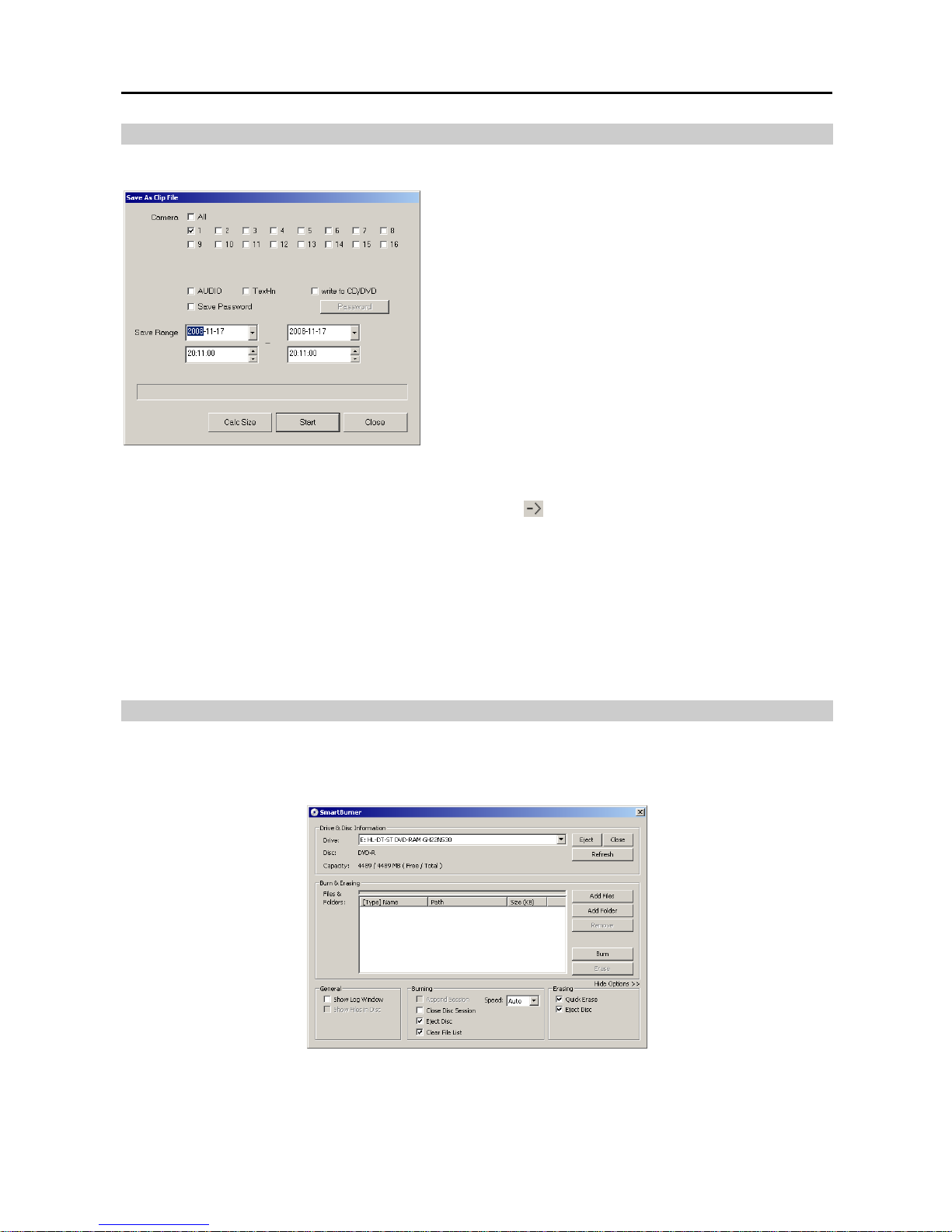
User’s Manual
32
Save As Clip File
Click the Save As Clip File radio button in the Save Type dialog box, and click the OK button.
Camera: Select the camera number to save.
AUDIO: Check the box to save audio with video.
Text-In: Check the box to save text-in data with video.
Write to CD/DVD: Check the box if you want to save the video
clip on the CD or DVD drive directly. The total file size of video
clips to save must be less than 2GB.
Save Password: Check the box and set up a password by clicking
the Password button if you want to ask the password for reviewing
the saved video clip.
Save Range: Set the saving range using the arrow buttons.
Calc Size: Calculates and preview the backup file size you are
saving.
Click the Start button to display the Save As dialog box. Designate
a folder path and enter a file name. Selecting Save saves video
according to the settings. Selecting Close cancels the saving operation
and closes the dialog box.
NOTE: When the write to CD/DVD box is checked, you need to select the CD or DVD recorder to use, and select
the folder name to save on the CD or DVD drive by clicking the
button. You can designate the folder path by
entering “/” between the directory name and file name. For example, if you enter "abank/test", a directory named
“abank” with an ‘.exe’ file named “test.exe” will be created.
NOTE: Writing on the DVD is available only on the Windows XP embedded version over 2.0.
NOTE: If the target disk for saving clip files is C:, it must have at least 800MB free space.
NOTE: When saving the video clips in the hard disk drive and the total file size reaches 2GB, you will be asked
to continue saving by creating multiple files in 2GB units. If you click the OK button, the system will continue saving
by creating multiple files in 2GB units.
NOTE: Refer to the Clip Player section (p. 33) for the reviewing the saved video clips.
Run CD/DVD Burner
Click the Run CD/DVD Burner radio button to initiate the CD/DVD burning program.
NOTE: The CD/DVD burning program will be selected during the SmartSearch Environment Setup. Refer to the
SmartSearch Environment Setup section (p. 36) for details.
Drive & Disc Information: Select the CD or DVD recorder to use. Click the Eject button if you want to eject the
media from the drive, and click the Close button if you want to close the drive door. Clicking the Refresh button
updates the list of connected recorder. Disc displays the disc information, and Capacity displays the disc capacity.
Page 39
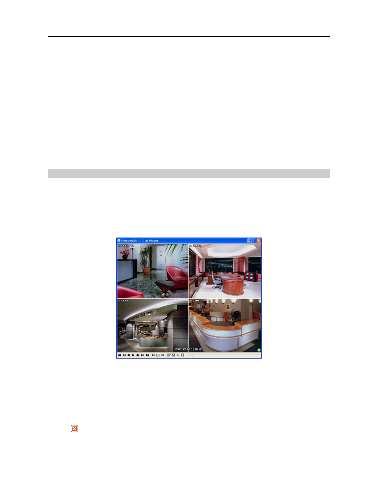
Digital Video Recorder
33
Burn & Erasing: Select the video files or folders to save after clicking the Add Files or Add Folder. Selected files
or folders will be displayed on the list. Clicking the Remove button deletes the selected files or folders. The capacity
bar above the list shows the data capacity. After selecting the files or folders to save, click the Burn button. Click
the Erase button to erase all data on the disc.
Options: Select Options to set up options required.
– General: Check the box beside Show Log Window to display the log list of the program, and check the box beside
Show Files in Disc to display files or folders saved on the selected disk.
– Burning: Check the box beside Append Session to save the new data subsequently following the previous data
session, and check the box beside Close Disc Session to complete the burning. Checking the box beside Clear
File List does not display the file or folder list. Select the burning speed from the Speed drop-down list. The
available speed options change depending on the CD/DVD burning program, and selecting Auto from the
drop-down list saves data in the fastest speed automatically.
– Erasing: Check the box beside Quick Erase to erase selected files more quickly, and check the box beside Eject
Disc to eject the disk automatically after completing burning or erasing.
NOTE: The burning might not be successful if the remaining space of the disk is not enough when saving the new
data subsequently following the previous data session.
Clip Player
You do not need to install any special software on your personal computer to review saved video clip. The file contains
a Player program. Double-clicking the target file starts the Player program.
NOTE: It is suggested that the computer used for the Player program has at least an 800MHz Pentium III. If your
CPU is slower than this, clip files recorded at maximum speed with very high image quality will be played back slowly.
NOTE: You will be asked to enter the password to initiate the Clip Player program if you select Save Password
option when saving recorded video.
NOTE: Proper image display depends on the display settings of your PC. If you are experiencing display problems,
click the right mouse button on the background screen and select Properties → Settings then set the Color quality to
“32 bit”. Then select Advanced → Troubleshoot, and then set the Hardware Acceleration to “Full”. Please make
sure that DirectX version 9.0 or higher has been installed if the display problem continues. To check the version of
DirectX, click Start → RUN and type “dxdiag” then hit the enter key which will display DirectX Diagnostic Tool dialog
box. Then move to the Display tab and make sure DirectDraw Acceleration is set to “Enabled”. Test DirectDraw
by selecting the DirectDraw Test button. Please check the driver version of the video card and update it to the
latest version available. If you still have display problems after changing all display settings as described above,
try replacing the video card. Video cards with an ATI chipset are recommended.
Clicking exits the Player program.
Playback Buttons: Plays back the current video on the screen.
Page 40
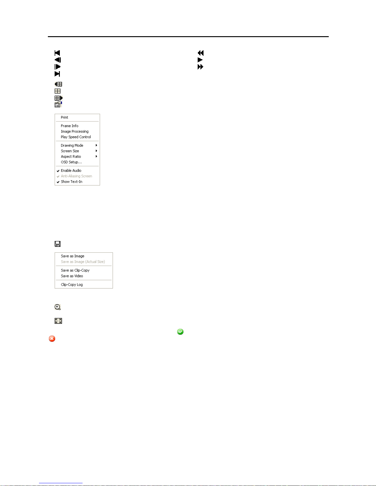
User’s Manual
34
Goes to the beginning of the video clip.
Plays the video clip in fast reverse.
Goes back one frame of the video clip.
Plays the video clip.
Goes forward one frame of the video clip.
Plays the video clip in fast forward.
Goes to the end of the video clip.
: Shows the previous camera group if there is recorded video in the previous camera group in the current screen mode.
: Cycles through the screen modes. It cycles through 2x2, 1+7, 3x3 and 4x4.
: Shows the next camera group if there is recorded video in the next camera group in the current screen mode.
: Sets up the Clip Player properties.
− Print: Prints the current image.
− Frame Info.: Displays Channel, Title, Time, Type, Size and Resolution information about
the image.
− Image Processing: Controls brightness, blur and sharpness of playback images. (Single
Screen Mode and Pause Mode Only)
− Play Speed Control: Changes the playback speed (Play) or fast forward/backward
playback speed (FF/RW).
− Drawing Mode: Selects the draw mode level. If you are not sure about the best draw mode
level for your system, try each level until the image displays properly.
− Screen Size: Changes the Clip Player screen size.
− Aspect Ratio: Changes the image aspect ratio displayed on each camera screen.
– OSD Setup…: Selects options to display on the screen.
– Enable Audio: Plays audio while playing back recorded video that has recorded audio. (Single Screen Mode Only)
– Anti-Aliasing Screen: Enhances image display quality on the screen by smoothing stair-stepping (aliasing) effects
in the enlarged image. If video plays slow because of your CPU’s slow speed, releasing the Anti-Aliasing Screen
option might improve playback speed.
– Show Text-In: Displays video with text-in data if the video was recorded with text-in data. (Single Screen Mode
Only)
: Saves clip images.
− Save as Image: Saves the current image as a bitmap or JPEG file.
− Save as Image (Actual Size): Saves the current video frame as a bitmap or JPEG
file in its actual size. (Single Screen Mode Only)
− Save as Clip-Copy: Saves video of desired time range as an executable file.
− Save as Video: Saves video of desired time range as an AVI file.
− Clip-Copy Log: Saves the clip copy log information as a text file. The user information
about Save As Clip Copy will be logged as “Internal-Copy.”
: Select from Normal and Double screen views (Single Screen Mode Only). You can move the enlarged image
by clicking the left mouse button and dragging.
: Displays the image full screen.
Encryption icons display in the bottom-right corner. displays when the clip file has not been tampered with, and
displays and playback stops when the system has detected tampering.
NOTE: If the VGA card or monitor does not support 800x600 video resolution, Full Screen might not display
properly. If this happens, press the ESC key on your PC keyboard to return to the normal screen mode.
Click the slider bar and move it left or right to move through the video clip.
Placing the mouse cursor on an image and clicking will cause that image to display full frame.
Page 41
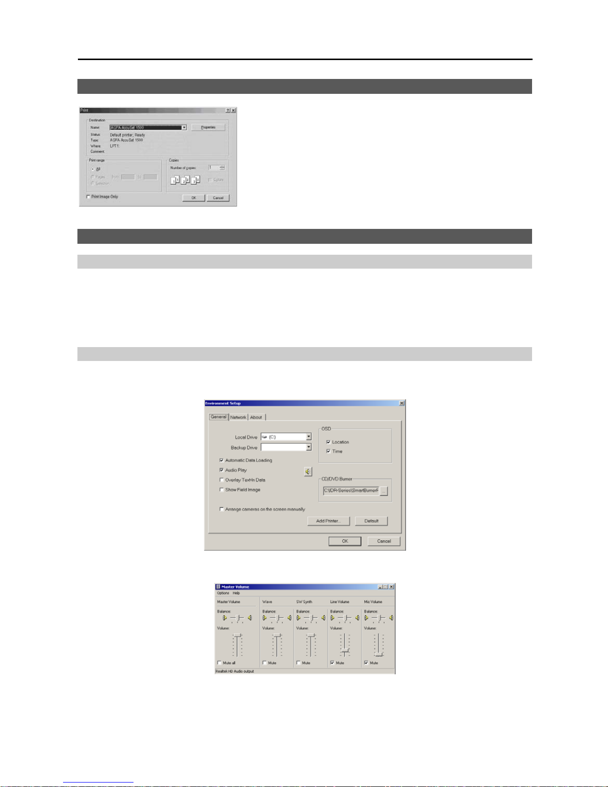
Digital Video Recorder
35
PRINTING CURRENT IMAGE
Name: Select an installed printer to use from the drop-down list.
Print range: Do not change the setting.
Copies: Set the number of copies using arrow buttons.
Print Image Only: Check the box if you want to print the image without
text information.
Click the OK button to print the current image. Selecting Cancel cancels
printing operations and closes the dialog box without saving the settings.
AUDIO PLAYBACK
Checking Audio Recording Configuration
1. Click the Guard button to access to the SmartGuard mode.
2. Click the Setup button on the main GUI of SmartGuard.
3. Move to the Sensor tab and/or Motion Detection
4. Check that Record Audio is selected.
5. Click the Setup Audio... button, and check that the audio input type is properly set.
Checking Audio Playback Configuration
1. Click the Search button on the main GUI of SmartGuard to return to the SmartSearch mode.
2. Click the Setup button on the main GUI of SmartSearch, and the Environment Setup screen appears.
3. Move to the General tab, and check that Audio Play is selected. Click the speaker icon, and check that the volume
in the Wave column is set properly.
Page 42
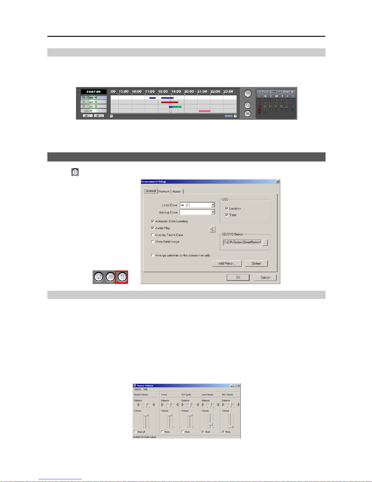
User’s Manual
36
Playing Recorded Audio
Click a playback button on the main GUI of SmartSearch. An Audio-play icon in the shape of a speaker will display
at the top left in the small playback screen if the target camera has recorded audio information. The recorded audio
time bar is located below camera 16, and its information is shown on the recording status bar in pink.
NOTE: Audio is played only in the single-screen mode and forward playback mode.
NOTE: Audio will NOT be played when the target camera was recorded less than two images per second.
SmartSearch ENVIRONMENT SETUP
Click the
(Setup) button in the Utility Buttons, and the Environment Setup screen appears.
General
Local Drive: Select the location of the local drive from the drop-down list. In most cases, the local drive is C:. Even
if the software is installed on more than one hard disk drive, the local drive will be C:, assuming that the operating
system (Windows) and the DVR program have been installed on the C: drive.
NOTE: It is recommended that you keep the C: drive as the default unless you are using the DVR for the test purposes.
Backup Drive: Select the folder path of the backup video to be played from the drop-down list.
Automatic Data Loading: Check the box to automatically load recorded data from the previous data loading path
when SmartSearch is initiated. If this box is not checked, you will need to select the data loading path manually by
clicking the Local, Remote or Backup buttons whenever initiating SmartSearch.
Audio Play: Check the box to listen to recorded audio in the playback mode. Click the speaker icon, and adjust
the volume in the Wave column if you want to set the volume of an installed speaker.
Page 43
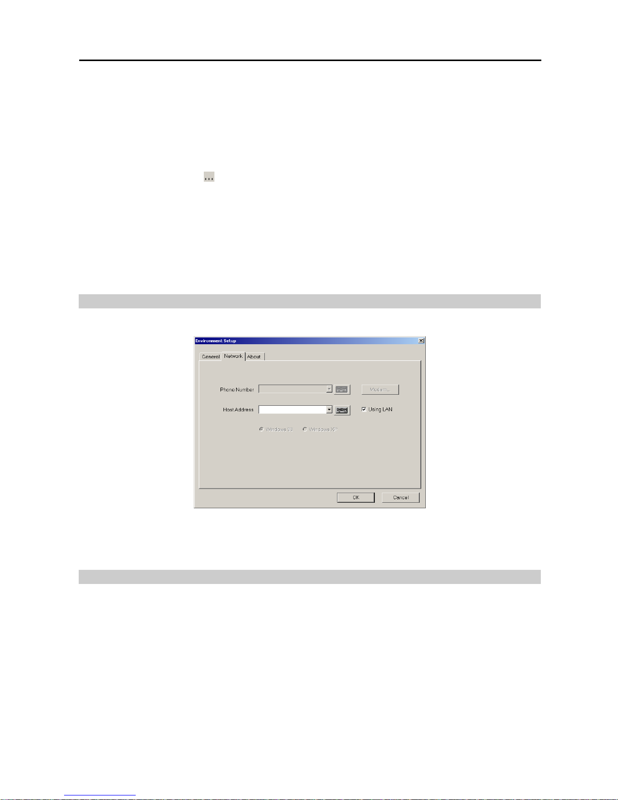
Digital Video Recorder
37
Overlay text-in data: Check the box to display the text-in information on the image. If this box is not checked,
the text-in information will be displayed on another dialog box.
Show Field Image: Check the box to display recorded video with 640x480 (704x480 (704x576 PAL) for PDR16-PC-RT
model) resolution as the field image not the frame image. This option may help to reduce distorted patterns that might
occur on frame images.
Arrange cameras on the screen manually: Check the box to arrange cameras manually at the desired location
of the playback screen. Refer to the Time-Lapse Search – Camera Label Buttons section (p. 30) for details.
OSD: Select the OSD information to be displayed on the playback image by checking the box next to desired options.
CD/DVD Burner: Click the
button to register the location where the CD/DVD burning program is. When using
the program provided by the CD/DVD burning manufacturer, select SmartBurnerPlus.exe in the C:\IDR-Series
folder. Recorded data can be saved on the CD or DVD drive by using the SmartBackup program. Refer to Chapter 4
— SmartBackup for details of the SmartBackup program.
NOTE: If the operating system version is lower than Windows XP Embedded 2.0, select SmartBurner.exe instead
of SmartBurnerPlus.exe. However, SmartBurner.exe will not support saving recorded data on the DVD drive.
Add Printer...: Set up the printer. Follow the instructions to install and set up the printer.
Default: Reset the system to default values. After you have changed all the settings, you can save your changes by
clicking the OK Button. Selecting Cancel exits the dialog box without saving the changes.
Network
Select the Network tab and set up network information for remote playback function.
Using LAN: Check the box when searching recorded images of other DVRs using a LAN.
Host Address: Click the arrow button and select the blank field. Enter the IP address using either the actual keyboard
or the virtual keyboard. You will need to get the appropriate IP address for the DVR you want to connect from your
network administrator.
About
Select the About tab and software version information is displayed.
Page 44

User’s Manual
38
Page 45
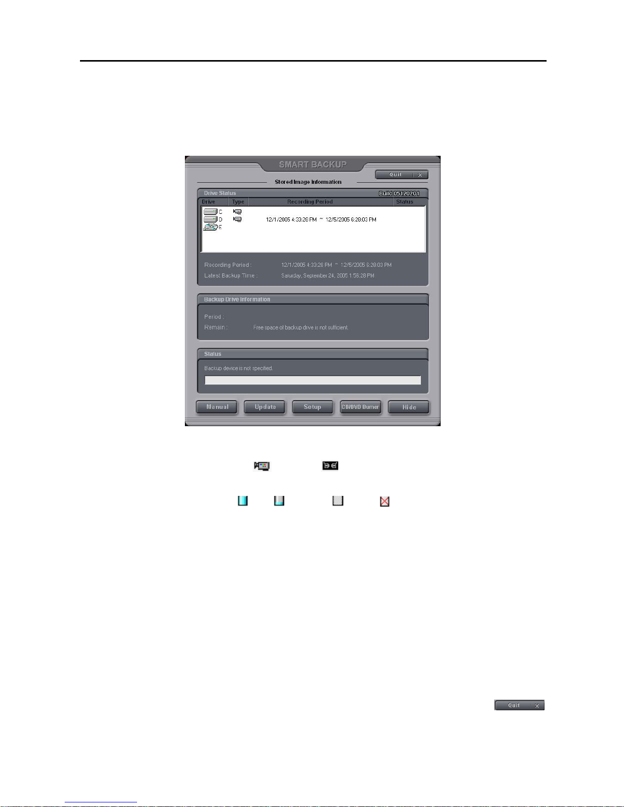
Digital Video Recorder
39
Chapter 4 — SmartBackup
To initiate the SmartBackup program, click the Setup button in the SmartGuard mode. Move to the System tab, and
click the Set up backup... button. The following SmartBackup dialog box appears.
Drive Status
– Drive: Shows all attached storage devices including hard disk drive(s), CD-RW and DVD RW drive.
– Type: Shows the usage of each drive (
: Recording, : Backup). When the drive is used for both recording
and backup, backup icon will be displayed.
– Recording Period: Shows the recording period contained on each (source or target) drive.
– Status: Shows the drive's status ( : Full, : Available, : Empty, : Not initialized).
– Recording Period: Shows the recording period contained on the recording drive.
– Latest Backup Time: Shows the latest backup date and time of the target drive.
Backup Drive Information
– Period: Shows the recording period contained on the backup drive.
– Remain: Calculates and shows the remaining space on the backup drive.
Status: Shows
backup drive status and a progress bar for the auto/manual backup.
Manual: Starts the manual backup mode. When the DVR is set to Auto Backup mode, this button will be inactivated.
Release the auto backup mode during the SmartBackup Setup if you want to set up the manual backup. Refer to the
Manual Backup section (p. 40) for setting up the manual backup.
Update: Updates the values in the SmartBackup dialog box. Recording Period, Latest Backup and Backup
Drive Information will be updated any time this button is selected.
Setup: Set up the backup information. Refer to the Setup section (p. 41) for details.
CD/DVD Burner: Save the backup data on the CD or DVD media using the CD/DVD burning program.
NOTE: The user can save recorded video when the user has an authority with External Save. The External Save
option should be selected during the SmartGuard – Authority setup. Refer to Chapter 2 — SmartGuard, Setting
Up the Authority for details.
Hide: Hides the SmartBackup dialog box. To close the dialog box and exit from the SmartBackup, click
at the top-right hand corner.
Page 46
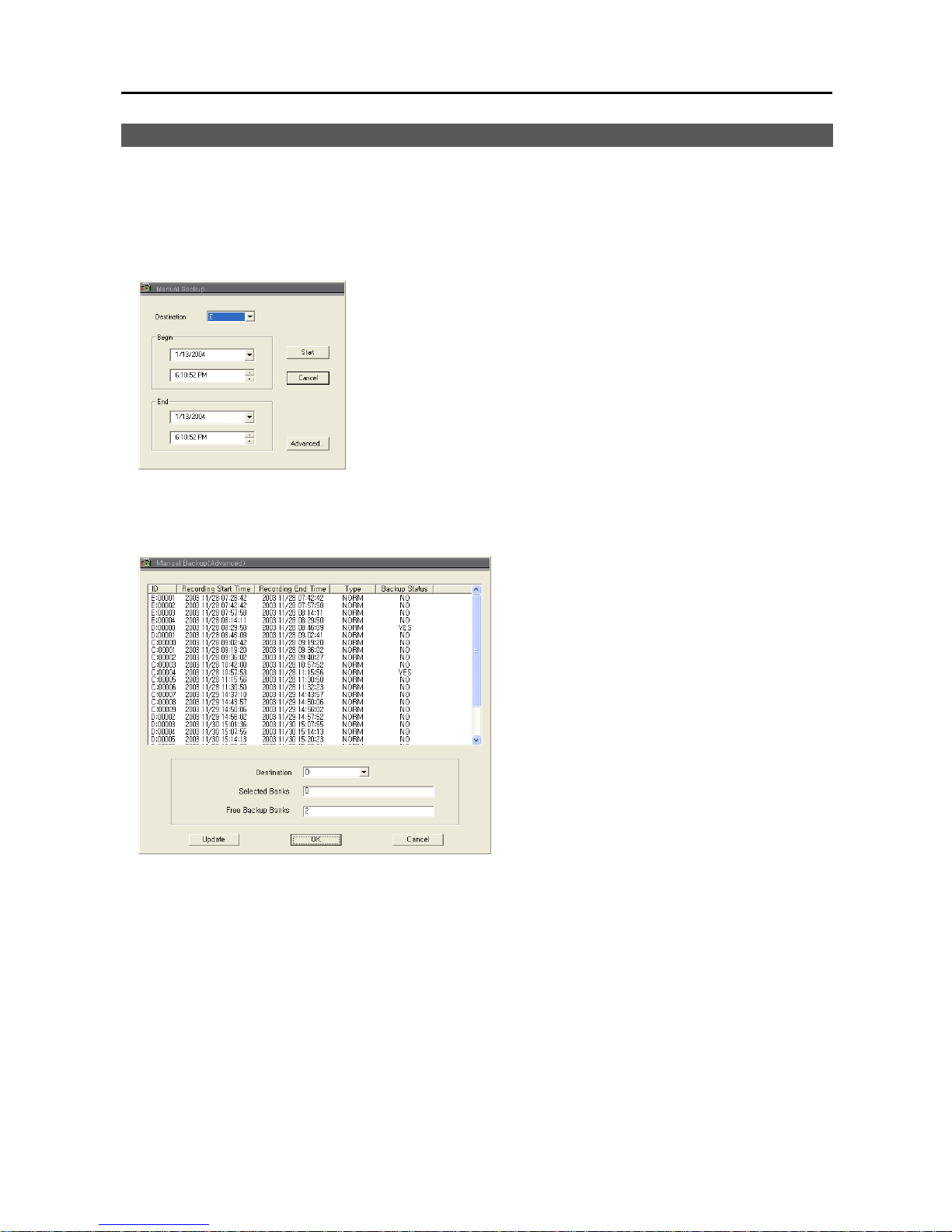
User’s Manual
40
MANUAL BACKUP
Click the Manual... button in the SmartBackup dialog box to start the manual backup mode. The following Manual
Backup dialog box appears. There are two ways to back up data manually; backup by time and backup by list.
CAUTION: Executing manual backup might decrease the recording speed or stop recording.
Manual Backup by Time
− Destination: Select a backup drive from a drop-down list.
− Begin: Set the backup beginning date and time. Select the beginning date
from the drop-down list, and set the beginning time using the arrow buttons.
− End: Set the backup ending date and time. Select the ending date from the
drop-down list, and set the ending time using the arrow buttons.
− Advanced: Manual Backup (Advanced) dialog box appears.
Click the Start button to start the manual backup by time. The DVR backs up
the recorded data from the established beginning date and time to the established
ending date and time. Only time-lapse mode recorded data will be backed up.
Selecting Cancel exits the dialog box without saving the settings.
NOTE: Backup of audio data, pre-event images, and text-in data can only be done by using the Manual Backup
by List. See the following Manual Backup by List section.
Manual Backup by List
Click the Advanced... button in the Manual Backup
dialog box.
− ID: Displays the serial number of the record banks.
− Recording Start Time / Recording End Time:
Displays the recording beginning date/time and ending
date/time of each bank.
− Type: Displays the type of record bank. Normal
means time-lapse recording, and PRExx means the
pre-event recording.
− Backup Status: Displays whether a target bank has
already been backed up or not.
− Destination: Select a backup drive from a drop-down
list.
− Selected Banks: Displays the number of selected
banks.
− Free Backup Banks: Displays the number of banks
that are available for backup.
Select the bank to back up by clicking the target bank in the list box. Multiple banks can be selected by using the
Ctrl or Shift keys on the actual keyboard. Click each bank to be backed up while pressing and holding the Ctrl key.
If you want to select all banks in a specific range, click the first and last banks to be backed up within the range while
pressing and holding the Shift key.
Click the Update button to update the record bank information. After you have set up the Manual Backup by List,
click the OK button. Selecting Cancel exits the dialog box without saving the settings.
NOTE: The BANK is the basic unit for the database used by the DVR system.
Page 47
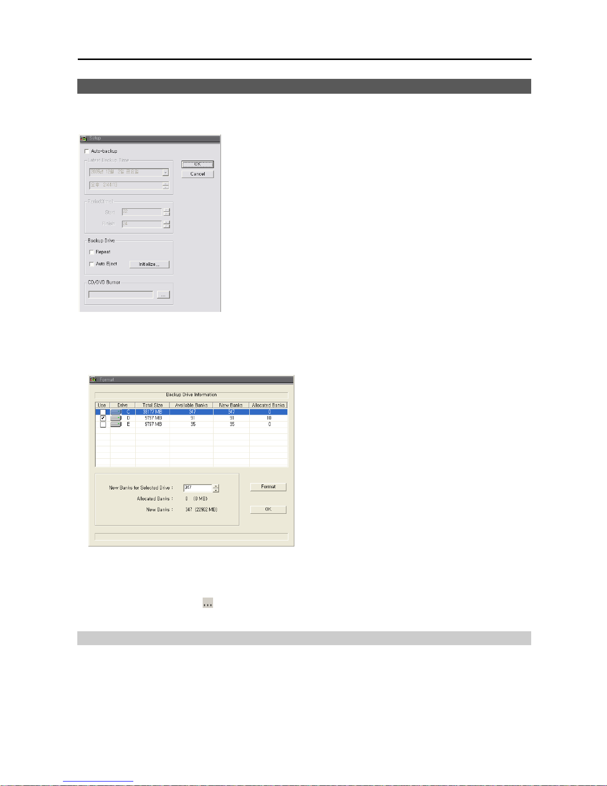
Digital Video Recorder
41
SETUP
Click the Setup... button in the SmartBackup dialog box to set up the backup information. The Setup dialog box
appears.
Auto-backup: Check the box to set up auto backup. If this box is checked,
the DVR will back up automatically according to the established auto backup
settings. If Auto-backup is not selected, the DVR is in the manual backup
mode and follows the established manual backup settings. Refer to the Manual
Backup section (p. 40) for setting up the manual backup.
NOTE: During Auto Backup, event recording data of camera channels that
are set under pre-event recording mode will NOT be backed up.
Latest Backup Time: Shows the latest backup date and time. When the
DVR is set to Auto Backup mode, only the banks recorded after Latest Backup
Time will be backed up.
Period (time): Set the backup beginning time in Start, and ending time in
Finish using the arrow buttons. If you set the value to 0 for the Start and to
24 for the Finish, the DVR will back up from 0:00 to 24:00 automatically
with checking out the bank periodically.
Backup Drive: If you want to recycle all the backup drive, click the Repeat box. If the Repeat box is not checked,
the DVR stops backing up when all the backup drive is full. Click the Auto Eject box to use the auto eject feature
of the backup drive if the drive is so equipped. Clicking the Initialize… button displays the following Format screen
and you can initialize the backup space. The backup drive should be initialized before backing up.
− Use: Check the box beside the drive to select it as a
backup drive. Multiple drives can be selected. Drive
displays the drive location, Total Size displays the total
size of the installed backup drive, and Available Banks
displays the number of available banks for backup.
− New Banks for Selected Drive: Set the number of
banks to be used for backup by using the arrow buttons.
− Allocated Banks: Will display the number of allocated
banks for backup after initializing.
− New Banks: Will display the number of banks to add.
− Format: Starts initializing the backup space of the
selected drive and allocates the banks according to the
setting.
NOTE: Repeat and Auto Eject cannot be selected at the same time.
NOTE: Active menus under the Backup Drive will vary depending on the type of media used.
NOTE: Any bank contents stored on the drive will be deleted when you initialize the backup drive.
CD/DVD Burner: Click the button. Register the CD/DVD burning program location to use. When using the
program provided by the CD/DVD burning manufacturer, select SmartBurnerPlus.exe in the C:\IDR-Series folder.
CD/DVD Burner
Click the CD/DVD Burner button in the SmartBackup dialog box to initiate the CD/DVD burning program registered
during the SmartBackup setup. Refer to the Run CD/DVD Burner section (p. 32) for the instructions on CD/DVD
burning.
NOTE: CD/DVD burning is not available during the automatic backup.
Page 48

User’s Manual
42
Target files for CD/DVD burning
Image files saved in SmartSearch mode.
Video files saved in SmartSearch mode.
Clip files saved in SmartSearch mode.
Whole ibbank directory on the drive used for backup.
Image files saved in the C:\IDR-Series\temp\RecordExt folder.
NOTE: The size of the ibbank directory should be smaller than the capacity of the CD or DVD drive. When using
the 650MB CDR or CDRW media, you must not exceed two backup banks.
Safeguards on Installing and Using the CD/DVD Burning Program
Do not install the DirectCD or HP-DLA programs for the system safety when installing the CD burning program.
Select the Buffer underrun prevention option when initiating the CD or DVD burning program. Selecting this option
can be different depending on the installing program.
Refer to the manual provided with the CD or DVD drive for instructions on burning the media.
Page 49
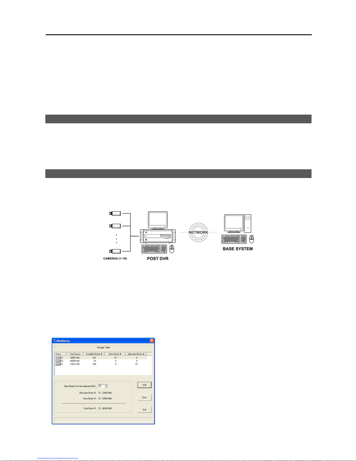
Digital Video Recorder
43
Chapter 5 — Remote Access
You can view video or control the DVR remotely via modem or LAN. For remote access, we provide the SmartBase
program. It has three major functions; remote monitoring, remote playback and remote control.
NOTE: A BASE system can view live video or review recorded video on POST systems. The POST system can
only review recorded video on other POST systems when they are networked via LAN.
RECOMMENDED BASE SYSTEM REQUIREMENTS
Operating System: Microsoft
®
Windows® XP x86 (32 Bit) (SP2 or higher), Microsoft® Windows® Vista x86 (32 Bit)
CPU: Intel Pentium IV or faster
RAM: 512MB or higher
VGA: Video RAM 16MB or higher (1024x768, 24bpp or higher)
BASE PROGRAM INSTALLATION
At least one POST DVR and a system for BASE are needed for using the remote access function. The POST is the
system to which the camera cables connect directly, and the BASE is the system which is installed at another site for
remote access. Install the BASE software at the remote site after installing the DVR.
CAUTION: If an older version of BASE software is installed on your computer, you should uninstall the
older version first.
NOTE: It is highly recommended to install the BASE software with the same or higher version than the POST system
software version.
1. Insert the installation CD.
2. Run the setup file (.exe) in the IDR Setup/Base folder, and install the software following the instructions.
3. When the IBankSetup screen appears, allocate banks to the BASE system to record images from the POST system.
NOTE: The BANK is the basic unit for the database used by the POST system and BASE system.
− Storage Table: Select the drive to allocate banks. Drive displays
the drive location, Total Space displays the total size of the
installed recording drive, and Available IBank # displays the
number of available banks for recording.
− New IBank # of the selected HDD: Set the number of banks
to be used for recording by using the arrow buttons.
− Allocated IBank #: Displays the number of allocated banks for
recording in all drives in the list.
− New IBank #: Displays the number of banks to add.
− Total IBank #: Displays the total number of allocated banks and
new banks in all drives in the list.
− Add: Creates a bank folder (IIBank) for recording in the selected
drive.
Page 50
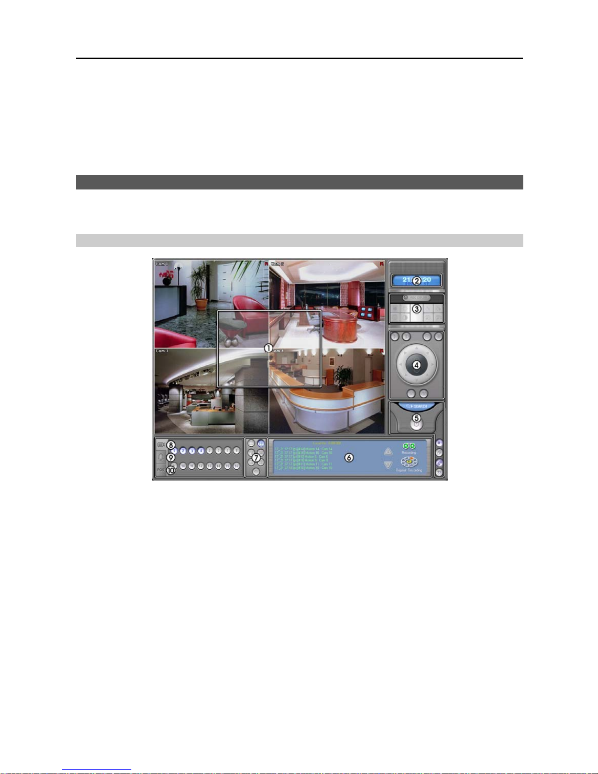
User’s Manual
44
– Clear: Starts initializing the bank of the selected drive and deletes all recorded data.
– Exit: Closes the IBankSetup screen.
NOTE: You can change the bank allocation for recording by running the IBankSetup program after completing the
BASE program installation (Go to the Start menu from the task bar
→ Programs → IDR-Series BASE → IBankSetup).
4. Run the SmartBase program after completing installation (Go to the Start menu from the task bar → Programs →
IDR-Series BASE → SmartBase).
SmartBase
SmartBase is remote monitoring and recording software. It allows remote monitoring of live camera images via network
connections and remote control of the PTZ cameras including the remote setup.
Main GUI
NOTE: If you do not use the overlay display mode on the SmartBase system, you can move the SmartBase window
at any place on the monitor by dragging the mouse.
① Monitoring Screen: Displays monitoring video. Various display formats (single-screen, full-screen, quad, 3+4,
3x3, 2+8, and 4x4) are provided for convenient user interface. The camera groups for multi-screen formats are
composed of cameras 1 to 16 in order. The user can select which camera group is displayed by clicking any camera
button in a group from camera buttons. Information including camera title, recording mode, and recording status
can be displayed on the image. Go to Setting Up the System and Setting Up Cameras in the SmartBase Setup section,
and place a check in the Show OSD box to display the OSD information.
② Clock: Displays date and time. Click the left mouse button on the clock area to set date display (MM-DD-YYYY/...)
and time display (12 Hours/24 Hours) formats. Click the right mouse button on the clock area to set date, time and
time zone.
CAUTION: If you change the time, images dated later than t he new date/time are deleted. Back up the im ages
if you want to save them.
③ Image Adjustment: Click to display image adjustment buttons. You can adjust the brightness, contrast, hue and
saturation of playback image by clicking the designated buttons. Click the Default button to reset them to the default
settings. Only the administrator can adjust the image. These adjustments should not be used to correct improperly
set cameras or monitors. Also, it is important that images are properly adjusted. These adjustments cannot make
up for improperly adjusted images when the images are recorded.
Page 51
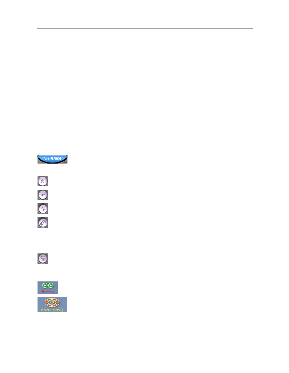
Digital Video Recorder
45
④ PTZ: Displays PTZ control buttons. Controlling PTZ from the SmartBase mode changes the PTZ setup of the remote
DVR. Only the administrator and authorized users for PTZ control can change PTZ setup from a remote site.
⑤ Utility Buttons: Refer to the Utility Buttons section below for details.
⑥ System Status: Displays operating mode, the remaining hard disk space and the type of hard disk usage, and also
displays system events. Refer to the System Status section below for details.
⑦ Screen Mode Buttons: Click the desired screen mode. Move the cursor to that image and double click the left
mouse button to view a specific image in the single-screen mode. Click the left mouse button in the window to return
to the previous screen mode from the single-screen mode..
⑧ Camera Buttons: Click to display the camera buttons. Clicking the individual camera buttons displays the selected
camera.
⑨ Alarm Control: Click to display alarm control buttons. You can check the alarm status and control the alarm output
remotely. Pressed alarm button is active mode, and released button is inactive mode. The user can active or inactive
alarm output manually by clicking the button when it is released or pressed. If the user disables the alarm during
the Alarm setup on the SmartGuard, the alarm button will be disabled. Only the administrator can control the alarm
output from a remote site.
⑩ POS: Click to display POS control buttons. The user can watch the text data coming from the POS remotely.
Utility Buttons
Accessing SmartSearch: Click the button to run the SmartSearch. If the SmartBase is connected
to the remote site, the SmartSearch will log in the same site automatically with the same login ID and
password.
Power: Click the button to quit or log out the system.
Connect: Click to connect to a remote site. Refer to the Remote Monitoring section (p. 46) for details.
Auto Sequencing: Click the button to sequence the cameras in order. Whenever you click the button, it
toggles between On and Off. The switching interval can be set during the system setup.
Record: The record mode is selected when this button is clicked. SmartBase returns to view only mode
automatically when it is unable to record (for example, when the hard disk is full).
NOTE: The BASE system records only in accordance with the recording schedule, which can be set during the
system setup. Before you install the BASE program, you need to fully understand the recording schedule. Note
also that clicking this recording mode button only prepares the BASE system for recording. In this state, the BASE
system will follow the recording schedule.
Setup: Click to connect to the remote DVR system or BASE system and to change settings. Refer to the
SmartBase Setup (p. 47) and Remote Setup (p. 50) sections.
System Status
Mode Status: There are two operating modes – View only mode and Recording mode. The
SmartBase records images only in the Recording mode.
HDD Indicator: Shows the remaining hard disk space and the type of hard disk usage. Click the
Setup button and move to the System tab in the setup dialog box. Select the between Once and
Recycle for HDD usage.
NOTE: Once (displayed as Disk available: **%) records until the hard disk is full and then stops. Recycle (displayed
as Repeat Recording) records over the oldest images when the hard disk is full.
Page 52
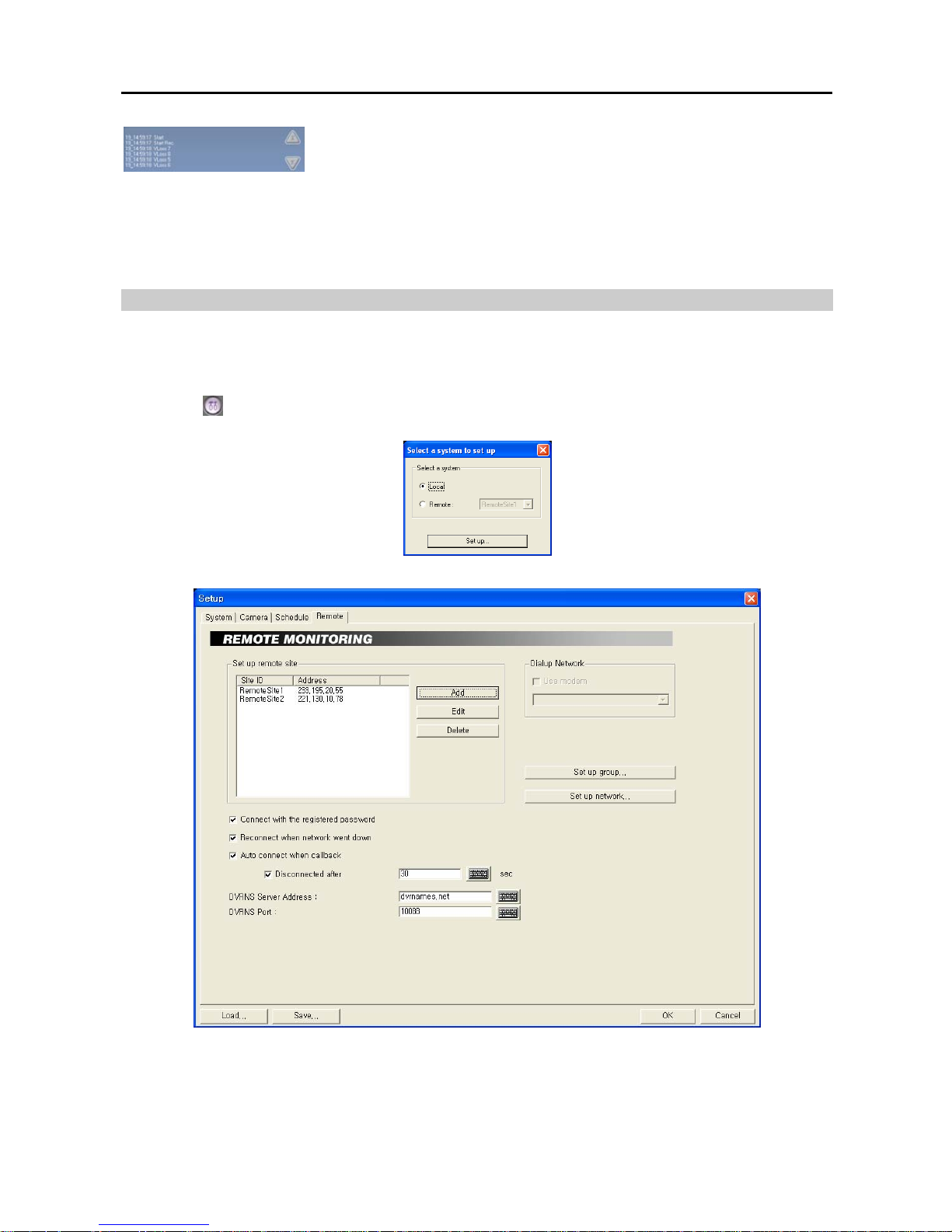
User’s Manual
46
Event Logging: Displays event logs and callback messages of the remote system.
To scroll up and down the list, hold down the left mouse button on the list and move
the cursor up and down, or roll the mouse wheel on the list. The display information
of the event log is as follows:
Event Log – ‘Date’_‘Time’ (User ID)
[Camera No. of the BASE system] ‘Event type’ ‘Camera No. of the POST system’ : ‘Camera title’
Callback Message – ‘Date’_‘Time’ (Callback)
‘Event type’ ‘Camera No. of the POST system’ : ‘Camera title’ (User ID)
Remote Monitoring
NOTE: Only the user who has an authority with Remote Monitoring can monitor live video on the remote DVR.
Check if the Remote Monitoring option for the user’s authorization is selected during the POST system setup. Refer
to
Chapter 2 — SmartGuard, Setting Up the Authority for details.
1. Click the
(Setup) button in the Utility Buttons on the main GUI of SmartBase, and the Select a system to set
up screen appears. Click the Local radio button and then click the Set up... button.
2. Select the Remote tab and add the desired remote sites.
Set up remote Site – Add: Register the remote site. Up to 256 sites can be registered.
Page 53
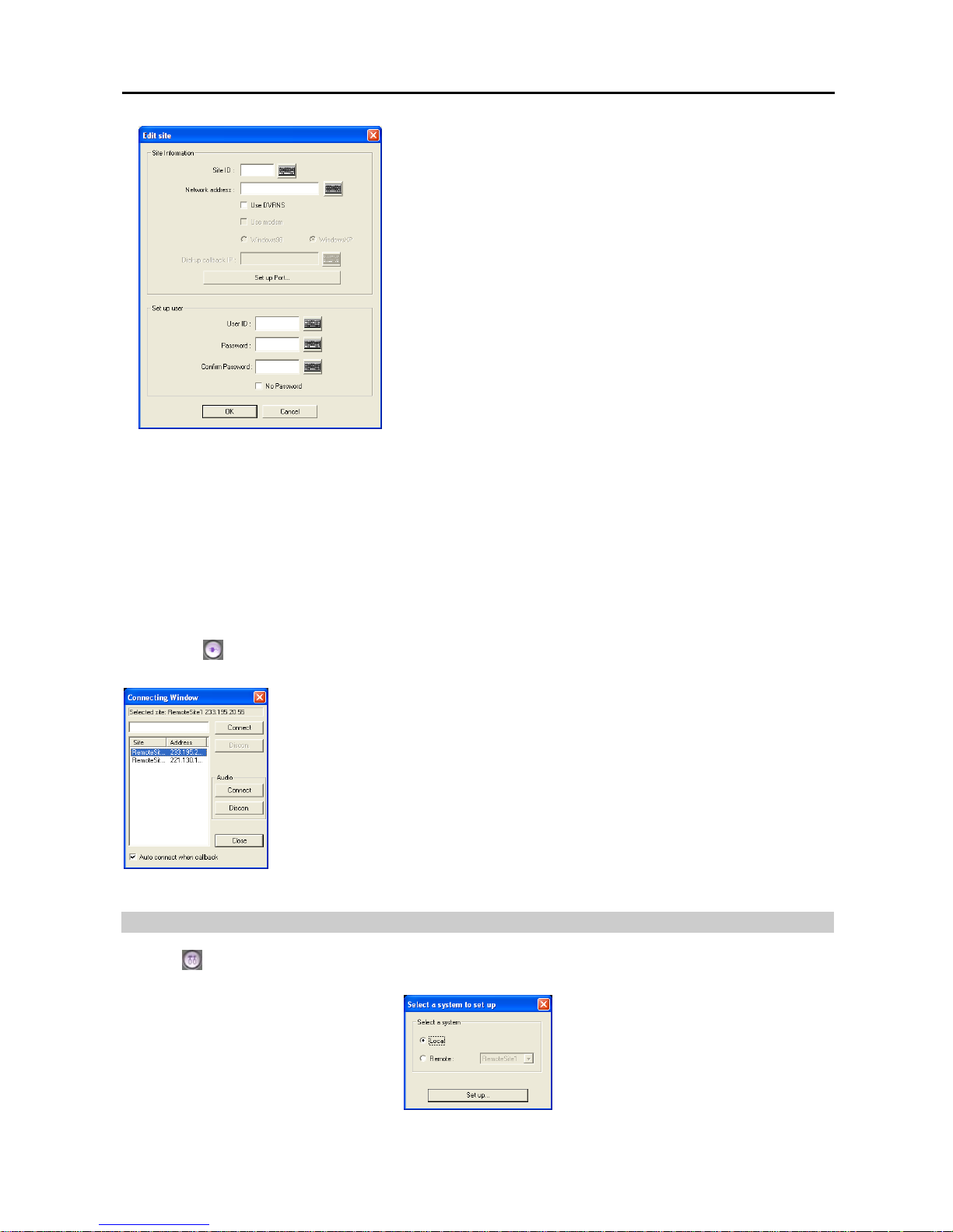
Digital Video Recorder
47
− Site ID: Enter the site name to register using either the actual keyboard
or the virtual keyboard.
− Network address: Enter the IP address of the remote DVR, acquired
from your network administrator. Move to Use modem, and check
the box when using a modem for remote access, and then select the
operating system on the BASE system; either Windows 98 or Windows
XP. For the remote connection via a modem, the dial-up networking
must be installed on the BASE system and the Phone number and
Dial-up callback IP should be entered.
− Set up Port…: Set up the port numbers. Click the text field beside
Remote Watch, Remote Search and Remote NetSound and enter
the appropriate port number of each program, acquired from your system
administrator to enable remote watch, remote search and two-way audio
communication between POST and BASE system. Clicking the Default
button resets all the port numbers to the default settings.
− User ID / Password: Enter the user ID (up to 16 characters) and
password (up to eight characters). Then click the text field beside
Confirm Password, and enter the user password again to confirm the
password. Move to No Password, and check the box when using a
User ID without a password.
Clicking the OK button saves the changes and returns to the Setup dialog box. Selecting Cancel exits the dialog box
without saving the changes.
NOTE: When using the DVRNS server, check the Use DVRNS box, and then enter the site name to register in
the Site ID field and the DVR name of the remote site in the Network ad dress field. The DVR name you enter should
match the DVR name set during the Remote Monitoring setup on the remote DVR.
NOTE: The same IP address entered during the dial-up callback setup on the POST system should be entered
on the BASE system. The independent IP address starting from 10.10.10.20 will be used to identify the remote
DVR systems.
3. Click the (Connect) button in the Utility Buttons on the main GUI of SmartBase, and the Connecting Window
screen appears.
A list of remote sites added in the Remote tab is displayed. Select a remote site to connect
from the list. You can also connect to a remote site by entering the site name or address in
the text field and then hitting the enter key. Click the Connect button under Audio if you
want to enable two-way (one-to-one) audio communication between POST and BASE.
Check the Auto connect when callback box if you want to connect to the remote site
automatically when receiving a callback message.
NOTE: If you want to arrange the site list in the descending orders, click the Site or Address
headings on the list box.
4. The live video of the connected remote site is displayed on the monitoring screen.
SmartBase Setup
Click the (Setup) button in the Utility Buttons on the main GUI of SmartBase, and the Select a system to set up
screen appears. Click the Local radio button and then click the Set up... button.
Page 54
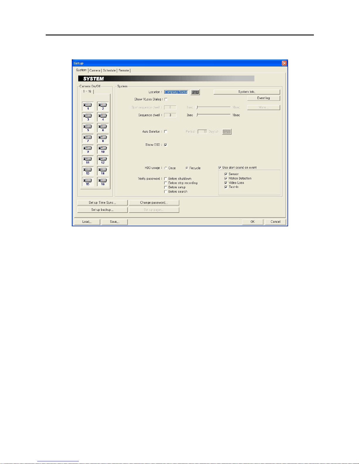
User’s Manual
48
Setting up System
Show VLoss Dialog: Check the box if you want to show the video loss acknowledge dialog when the video loss
is detected.
Event log: Displays the event log list of the BASE system.
Show OSD: Check the box if you want to show OSD information including camera title, recording mode, recording
status and event detection results on the image.
Verify password: Check the boxes to use a password Before shutdown, Before stop recording, Before setup,
and/or Before search.
Use alert sound on event: Check the box if you want the system to alert for the selected events when events occur.
You can set up the BASE system to play different alert sounds for each type of event. Create sound files (.wav) for
each type of event under program installation folder and name the sound files: sensor.wav for alarm-in, motion.wav
for motion detection, vloss.wav for video loss and textin.wav for text-in.
NOTE: The BASE system plays different alert sounds for each type of event when receiving a callback message
if you designate an alert sound for each type of event.
Change password…: Change the password. The default password is 111.
Page 55
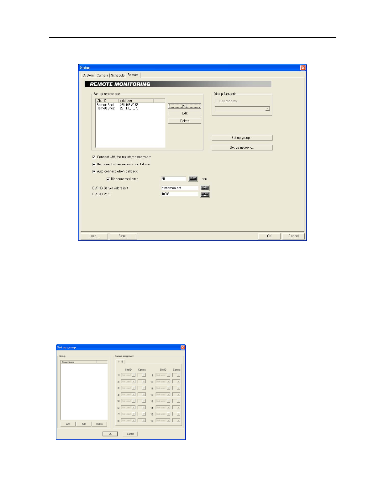
Digital Video Recorder
49
Setting up Remote
Connect with the registered password: If this box is checked, the remote DVR will be connected automatically
with registered user ID and password. If there is no registered password, the login dialog box will appear. The
connection fails when an incorrect password is entered.
Reconnect when network went down: Check the box if you want to reconnect the remote site automatically when
you are disconnected from the remote site for network problems.
Auto connect when callback…: Check the box if you want to connect the remote site automatically when the BASE
system receives a callback message. This auto callback connection can be disconnected automatically if you check
the Disconnect after box and set the desired disconnection time.
Dialup Network: Check the Use modem box when using a modem for remote access, and then select a modem
to use from the drop-down list.
Set up group...: Set up the group management. The BASE system can monitor up to 16 remote DVRs simultaneously.
For the effective management of the remote DVRs, the user can register multiple remote DVRs in one group. Up
to 64 groups can be registered.
− Group: Set up the group information. Click the Add button
to register a new group, and enter the name of the group to
register.
− Camera assignment: Select the target remote site from
the Site ID drop-down list and camera number from the
Camera drop-down list.
NOTE: If you want to edit the established group information,
click the Edit button after selecting a registered group from
the list. Then, edit the group information. If you want to
delete a registered group, click the Delete button after
selecting a registered group from the list.
Set up network...: Set up the network. Refer to Appendix 3 — Network Setup.
Page 56
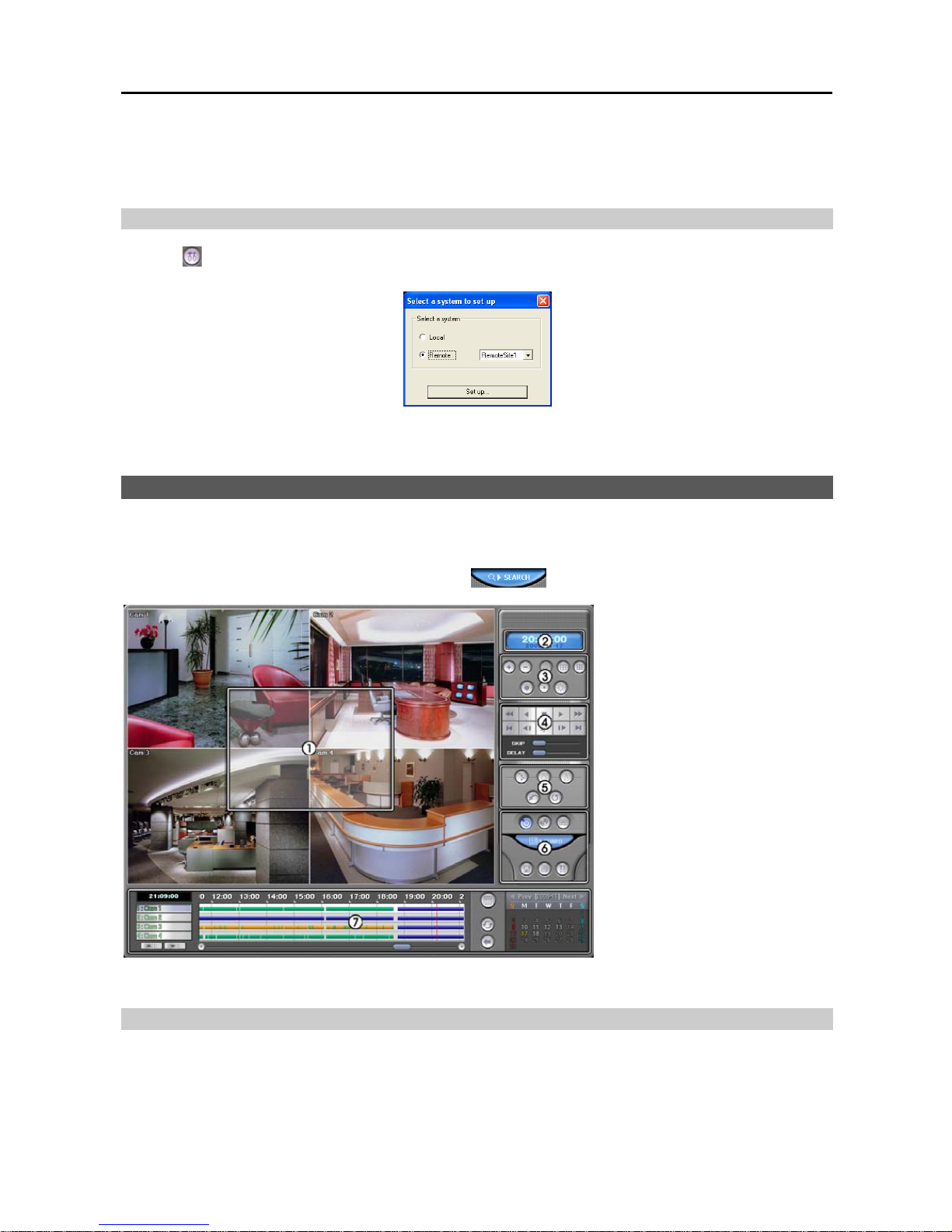
User’s Manual
50
After you have changed the settings, you can save your changes by clicking the OK button. Selecting Cancel exits
the dialog box without saving the changes.
NOTE: Refer to the Chapter 2 — SmartGuard section for setting up Camera and Schedule menus.
Remote Setup
Click the (Setup) button in the Utility Buttons on the main GUI of SmartBase, and the Select a system to set up
screen appears. Click the Remote radio button and select a remote site to connect from the list.
NOTE: Refer to the Chapter 2 — SmartGuard section for setting up each menu.
SmartSearch
SmartSearch is remote and local playback software. It allows playing back video recorded or backed up in the remote
DVR system or BASE system.
The user can access the SmartSearch mode by clicking the
(Search) button on the main GUI of SmartBase.
① Playback Screen
②
Clock
③ Image Adjustment Buttons
④ Playback Control
⑤ Image Processing Buttons
⑥ Utility Buttons
⑦
Timetable
NOTE: See Chapter 3 — SmartSearch for details on each button and its function.
Remote Playback of Recorded Video
You can play back video recorded in the remote DVR system.
NOTE: Only the user who has an authority with Remote Search can play back video recorded in the remote DVR.
Check if the Remote Search option for the user’s authorization is selected during the POST system setup. Refer to
Chapter 2 — SmartGuard, Setting Up the Authority for details.
Page 57
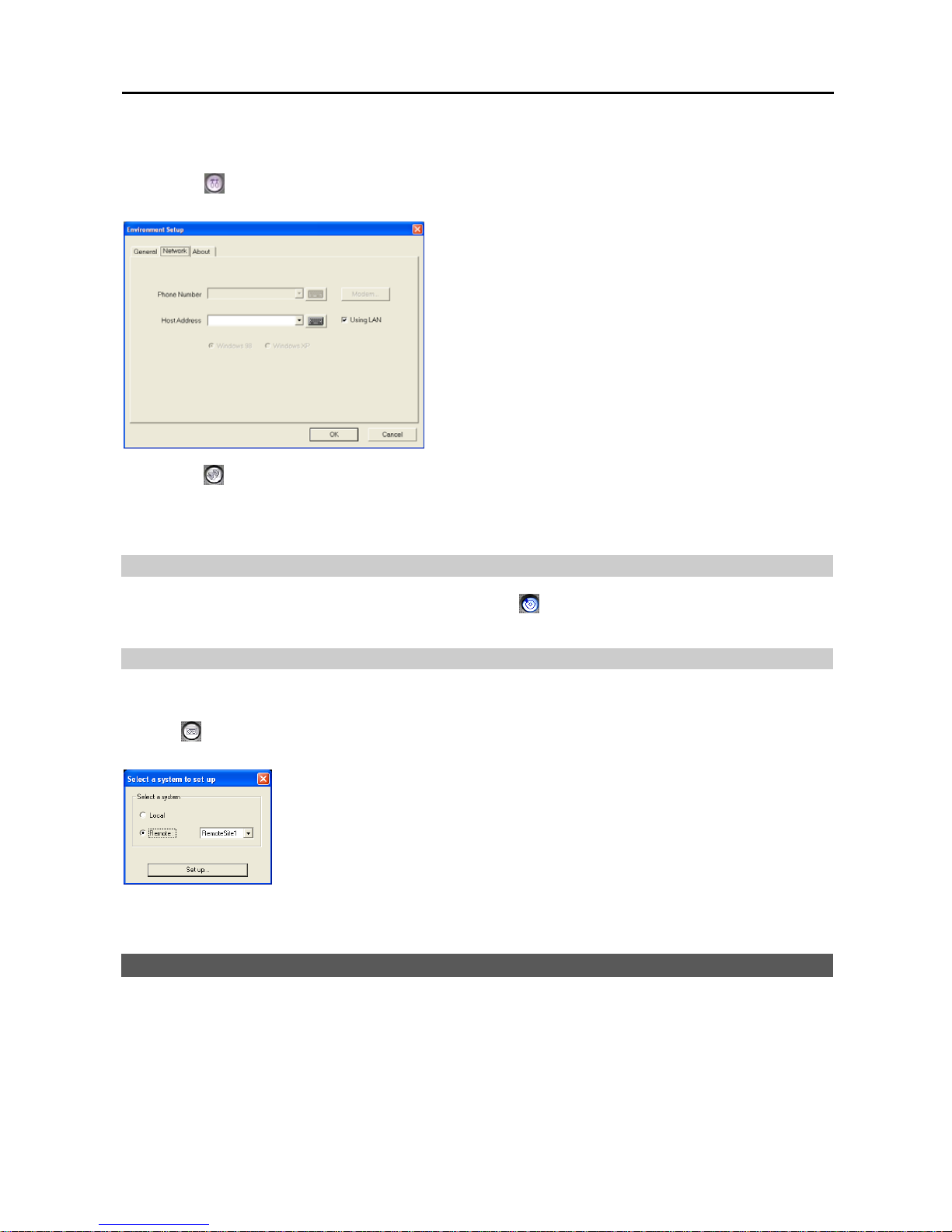
Digital Video Recorder
51
NOTE: During the remote playback on the BASE system, the information about recorded audio will be shown on
the timetable.
1. Click the
(Setup) button in the Utility Buttons on the main GUI of SmartSearch, and the Environment Setup
dialog box appears. Set up the network information for remote playback.
Using LAN: Check the box when searching recorded or backup
images of other DVRs using a LAN.
Host Address: Click the arrow button and select the blank field.
Enter the IP address using either the actual keyboard or the virtual
keyboard. You will need to get the appropriate IP address for
the DVR you want to connect from your network administrator.
2. Click the
(Remote) button in the Utility Buttons on the main GUI of SmartSearch, and the Remote Site dialog
box appears. Select a remote site to connect from the site list added for remote monitoring and click the Con. button.
Video recorded in the connected site is displayed on the playback screen. Refer to Chapter 3 — SmartSearch,
Utility Buttons for details.
Local Playback of Recorded Video
You can play back video recorded in the BASE system. Click the
(Local) button in the Utility Buttons on the main
GUI of SmartSearch, and video recorded in the BASE system is displayed on the playback screen.
Remote and Local Playback of Backup Video
You can play back video backed up in the remote DVR system or BASE system.
Click the
(Backup) button in the Utility Buttons on the main GUI of SmartSearch, and the Select a system dialog
box appears.
Local: Searches for video backed up in the BASE system.
Remote: Searches for video backed up in the remote DVR system. A list of sites added
during SmartBase – Remote Monitoring, Set up remote site setup is displayed in the drop-
down menu.
NOTE: See Chapter 3 — SmartSearch for setting up and using the SmartSearch.
SmartBackup
SmartBackup is backup software. It allows you to back up video recorded in the BASE system. See Chapter 4 —
SmartBackup for setting up and using the SmartBackup.
Page 58

User’s Manual
52
Page 59
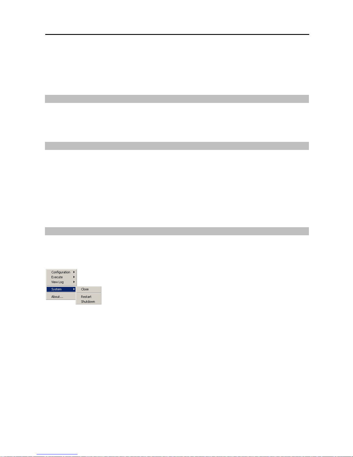
Digital Video Recorder
53
Appendix 1 — Accessing Windows
Since the DVR is new technology, it might be unfamiliar to many users. Many problems can occur from incorrect
Windows settings. The DVR requires specific Windows settings for optimal performance. That is why the Windows
mode has been blocked. This section describes the steps to get into the Windows mode.
The Relationship Between "Accessing Windows" and "SmartShell"
The SmartShell is the only way to get into the Windows mode. See Appendix 2 — SmartShell. To access Windows,
you must be in the SmartShell mode because the DVR will shut down when you click the POWER button in the
SmartGuard mode. Use the following instructions to change the Automatic Shutdown mode so that you will to be able
to access Windows.
How to Access the Automatic Shutdown Hidden Dialog Box
1. Double click the logo (or empty space) located above the Rec button in the SmartGuard mode. The splash window
appears.
2. Type idisman and press the Enter key on the keyboard. A small dialog box appears.
3. Move to Automatic Shutdown, and check the box to shutdown the DVR when you end SmartGuard. If this box
is not checked, the DVR will enter the Windows mode via the SmartShell when shutting down SmartGuard.
4. You can save your changes by clicking the OK button. Selecting Cancel exits the dialog box without saving the
changes.
CAUTION: Do NOT chang e other opti ons and kee p the fact ory default setti ng. Ask y our system admi nistrator
about other options in the hidden dialog box.
How to Access Windows
If you release the Automatic Shutdown mode in the hidden dialog box, clicking the POWER button in the SmartGuard
mode causes the DVR to enter the SmartShell mode. Click the right mouse button in the SmartShell mode. The following
Menu dialog box appears.
Click System to open options, and select Close. The DVR will enter the Windows mode.
To return to the DVR programs, click the Start button on the Task Bar, move the cursor to
Programs, and then to DVR to open the program list. Select SmartShell. The DVR will
enter the SmartGuard mode via the SmartShell.
Page 60
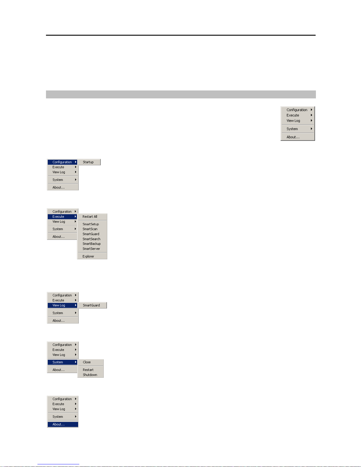
User’s Manual
54
Appendix 2 — SmartShell
SmartShell is very easy and dependable software for maintaining your DVR. The software will help the DVR recover
from unexpected system failures. SmartShell is also the only way to access Windows.
How to Access SmartShell
If you release the automatic shutdown mode in the hidden dialog box, clicking the POWER button
in the SmartGuard mode enters the SmartShell mode. Click the right mouse button in the SmartShell
mode. The following Menu dialog box appears.
Configuration Menu
Startup: Configures the startup programs of the DVR.
Execute Menu
Restart All: Restarts the programs.
SmartSetup: Enters the SmartSetup program to set up the IBank, the database of the
DVR. Ask your system administrator for details about the IBanks setup.
SmartScan: This is invisible software that scans the hard disk drive for recording.
SmartGuard: Enters the SmartGuard program.
SmartSearch: Enters the SmartSearch program.
SmartBackup: Enters the SmartBackup program.
SmartServer: This is invisible software that prepares images for transmitting to remote
sites via modem or LAN.
Explorer: Initiates Explorer without accessing Windows.
View Log Menu
SmartGuard: Displays the log file that logs every operation of the DVR.
System Menu
Close: Closes SmartShell and accesses Windows.
Restart: Restarts the DVR.
Shutdown: Shuts down the DVR.
About... Menu
About...: Displays the software version information.
Page 61
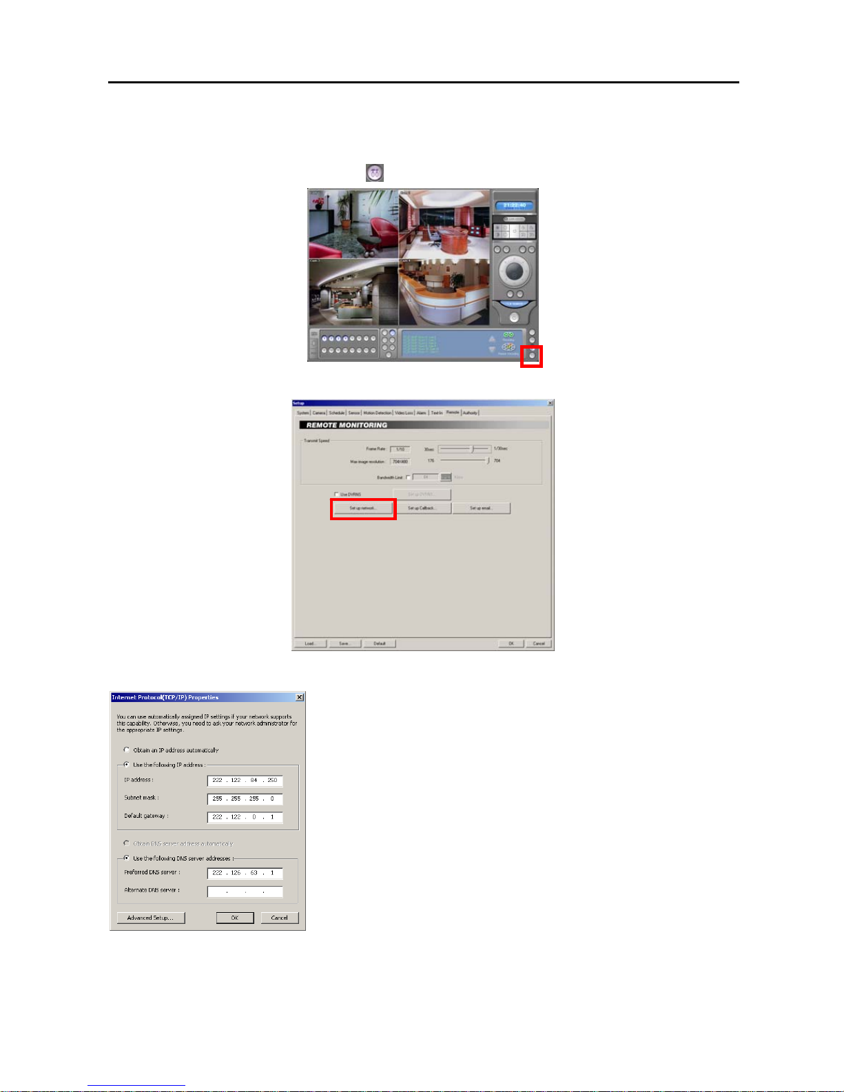
Digital Video Recorder
55
Appendix 3 — Network Setup (LAN)
1. Run the SmartGuard program and click the
(Setup) button on the main GUI.
2. Select the Remote tab and the Remote Monitoring setup screen appears. Click the Set up network… button.
3. Clicking the Set up network… button displays Internet Protocol(TCP/IP) Properties screen.
Select Obtain an IP address automatically or Use the following IP address
depending on your network environment. When selecting Obtain an IP address
automatically, the DNS server address is set up automatically. When selecting
Use the following IP address, enter the IP address, Subnet mask, Default
gateway and DNS server address acquired from your network administrator.
Page 62
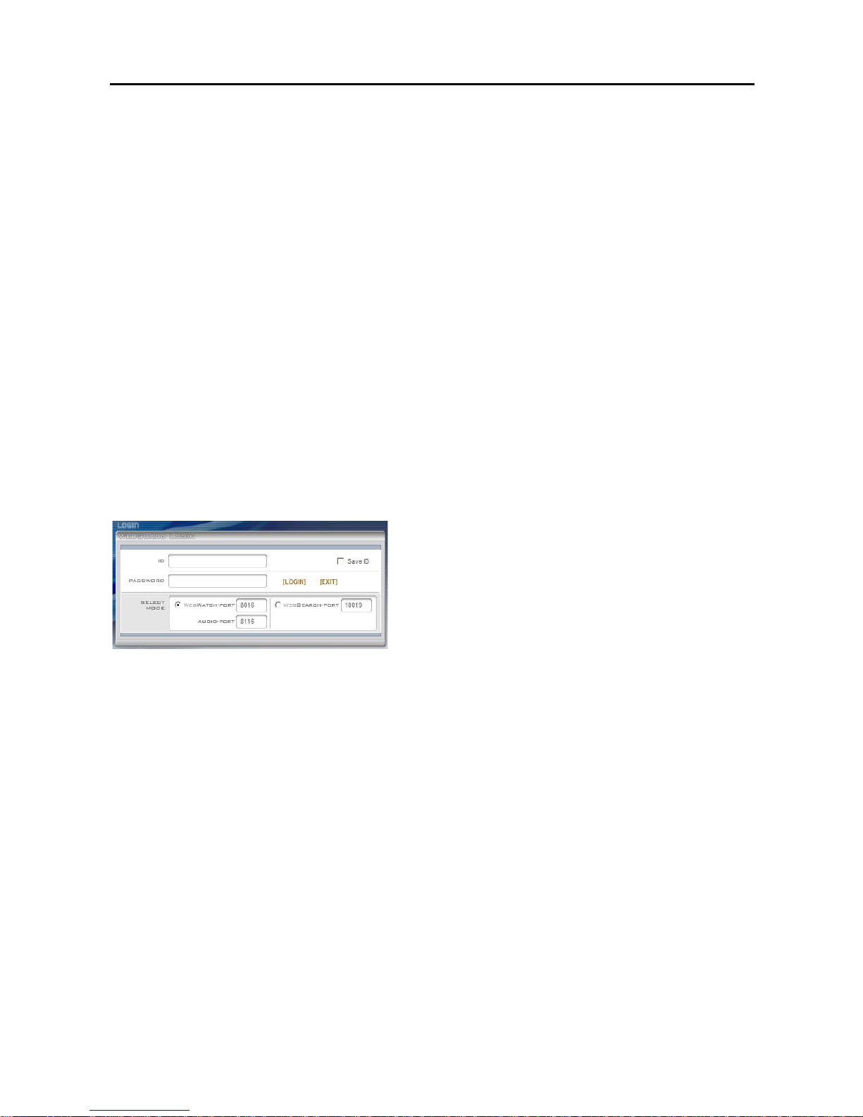
User’s Manual
56
Appendix 4 — WebGuard
WebGuard allows you to access a remote DVR, monitor live video images and search recorded video using Internet
Explorer web browser anytime from virtually anywhere.
Computer system requirements for using the WebGuard program are:
Operating System: Microsoft
®
Windows® 2000, Microsoft® Windows® XP or Microsoft® Windows® Vista
CPU: Intel Pentium III (Celeron) 600MHz or faster
RAM: 128MB or higher
VGA: 8MB or higher (1024x768, 24bpp or higher)
Internet Explorer: Version 6.0 or later
Start Internet Explorer on your local PC. You can run the WebGuard program by entering the following information
in the address field.
– “http://IP address” (The DVR IP address)
– Or, “http://DVRNS server address/DVR name” (The DVRNS server address and the DVR name registered on the
DVRNS server)
– Or, “http://www.dvronline.net” (Entering the DVR IP address or the DVR name will be required when logging in)
NOTE: You will need to get the appropriate IP address for the DVR you want to connect from your network
administrator.
NOTE: WebGuard only works with Microsoft Internet Explorer and will NOT work with other web browsers.
Select between the WEBWATCH (Web monitoring) and
WEBSEARCH (Web search) modes and enter the appropriate
port number of the program. Entering ID and PASSWORD and
clicking the [LOGIN] button logs in using the selected mode.
Selecting Save ID saves the ID you entered.
You will need to enter the DVR IP address in the DVR ADDRESS field when running the WebGuard program by
entering http://www.dvronline.net. Selecting the Use DVRNS option allows you to enter the DVR name registered
on the DVRNS server instead of the IP address. It is required to enter the DVRNS server address and port number
during the SETUP setting when selecting the Use DVRNS option.
NOTE: You will need to get the appropriate port number for each program from your system administrator.
NOTE: When running the updated WebGuard for the first time, Internet Explorer might occasionally load the information
from the previous version. In this case, delete the temporary Internet files by selecting Tools → Internet Options →
General tab, and then run WebGuard again.
NOTE: There might be a problem with the bottom of WebGuard page being cropped caused by the address or
status bars in Microsoft Internet Explorer 7.0. In this situation, it is recommended that websites open windows
without address or status bars by changing Internet setting. (Go to Tools and Internet Options, and then the Security
tab → Click the Custom level… button → Select Enable for the Allow websites to open w indows without address
or status bars option).
NOTE: When running WebGuard in the Microsoft Windows Vista operating system, it is recommended to start
Internet Explorer with elevated administrator permissions. Click the right mouse button on the Internet Explorer
icon and select the Run as administrator option from the context menu. Otherwise, some functions of the WebGuard
might be limited to use.
Page 63
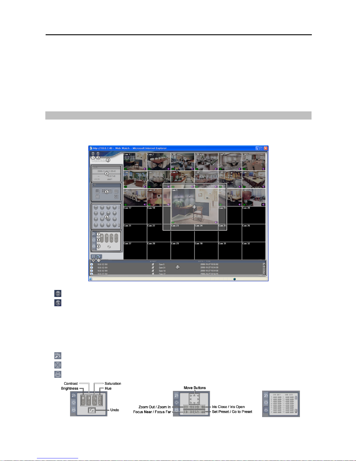
Digital Video Recorder
57
NOTE: There might be a problem with screen display or screen update due to low image transmission speed when
using the Microsoft Windows Vista operating system. In this situation, it is recommended that you disable the Auto
Tuning capability of your computer.
Run the Command Prompt with elevated administrator permissions (Go to the Start Menu and Accessories,
and then Command Prompt → Click the right mouse button and select the Run as administrator option). Then
enter “netsh int tcp set global autotuninglevel=disable” and press the enter key. Restart your computer to apply
the changes.
If you want to enable the Auto Tuning capability again, enter “netsh int tcp set global autotuninglevel=normal” after
running the Command Prompt with elevated administrator permissions. Restart your computer to apply the changes.
Web Monitoring Mode
WebWatch is a remote web monitoring program that allows you to monitor live video transmitted in real-time from
the remote DVR.
① : Click to log out the WebGuard program.
② : Click to access to the web search mode.
③ Position the mouse pointer on the WebWatch logo to see the version of the WebGuard program.
④ The DVR information window displays the login information of WebGuard.
⑤ Click the screen format to select the desired display mode. When changing the screen format, the selected camera
on the current screen will locate at the first cell of the layout to be changed.
⑥ Click the camera button to select the camera to be viewed.
⑦ : Click to adjust the brightness, contrast, saturation and hue of monitoring image.
⑧ : Click to control pan, tilt and zoom of the camera from a remote site.
⑨ : Click to control alarm out devices at the remote site.
Page 64
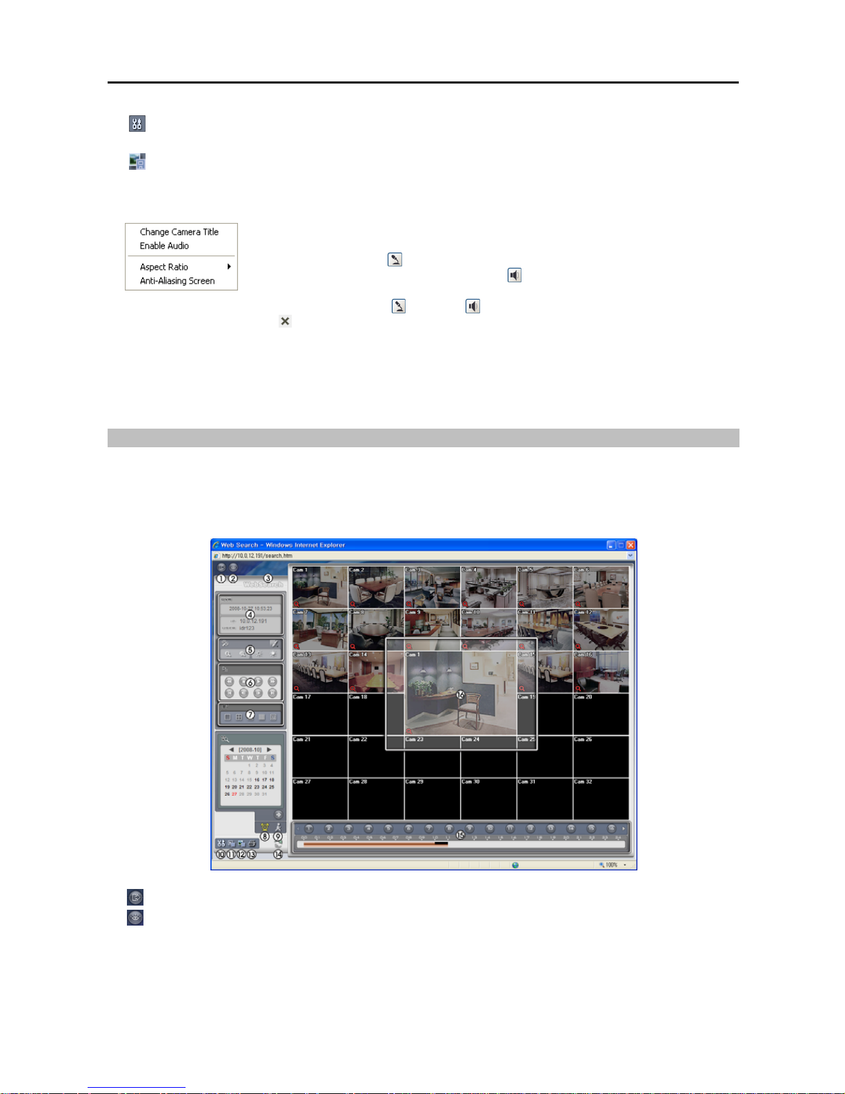
User’s Manual
58
⑩ : Click to set up the image drawing mode and OSD display. You can adjust the display speed by changing the
image drawing mode, and select OSD information to be displayed on the screen.
⑪ : Click to save the current image as a bitmap or JPEG file format.
⑫ The event status window at the bottom displays a list of events that were detected from the remote site.
⑬ Selecting a camera on the screen and clicking the right mouse button displays the text menu screen.
Change Camera Title: Changes the camera name.
Enable Audio: Enables audio communication with the remote site. When the audio control
panel displays, click the
button to send audio to the connected remote site and click the
button again to stop sending audio. Click the
button to monitor live audio from the
connected remote site through the attached speaker and click the button again stop monitoring
live audio. Clicking both button and button allows two-way communication. Clicking
the
button disables audio communication.
Aspect Ratio: Changes the image aspect ratio.
Anti-Aliasing Screen: Enhances image display quality by eliminating stair stepping (aliasing)
effects in the enlarged image.
NOTE: A camera name change in the Web Watch mode does not affect the camera name set up on the remote
site. Leaving the Camera Title blank causes the camera name set up on the remote site to display.
Web Search Mode
WebSearch is a remote web search program that allows you to search recorded video on the remote DVR.
NOTE: The remote site connection on the Web Search screen will automatically be disconnected if there is no
activity for 30 minutes.
①
: Click to log out the WebGuard program.
②
: Click to access to the web monitoring mode.
③ Position the mouse pointer on the WebSearch logo to see the version of the WebGuard program.
④ The DVR Info. window displays the time information of recorded data on the remote DVR and login information
of WebGuard.
Page 65
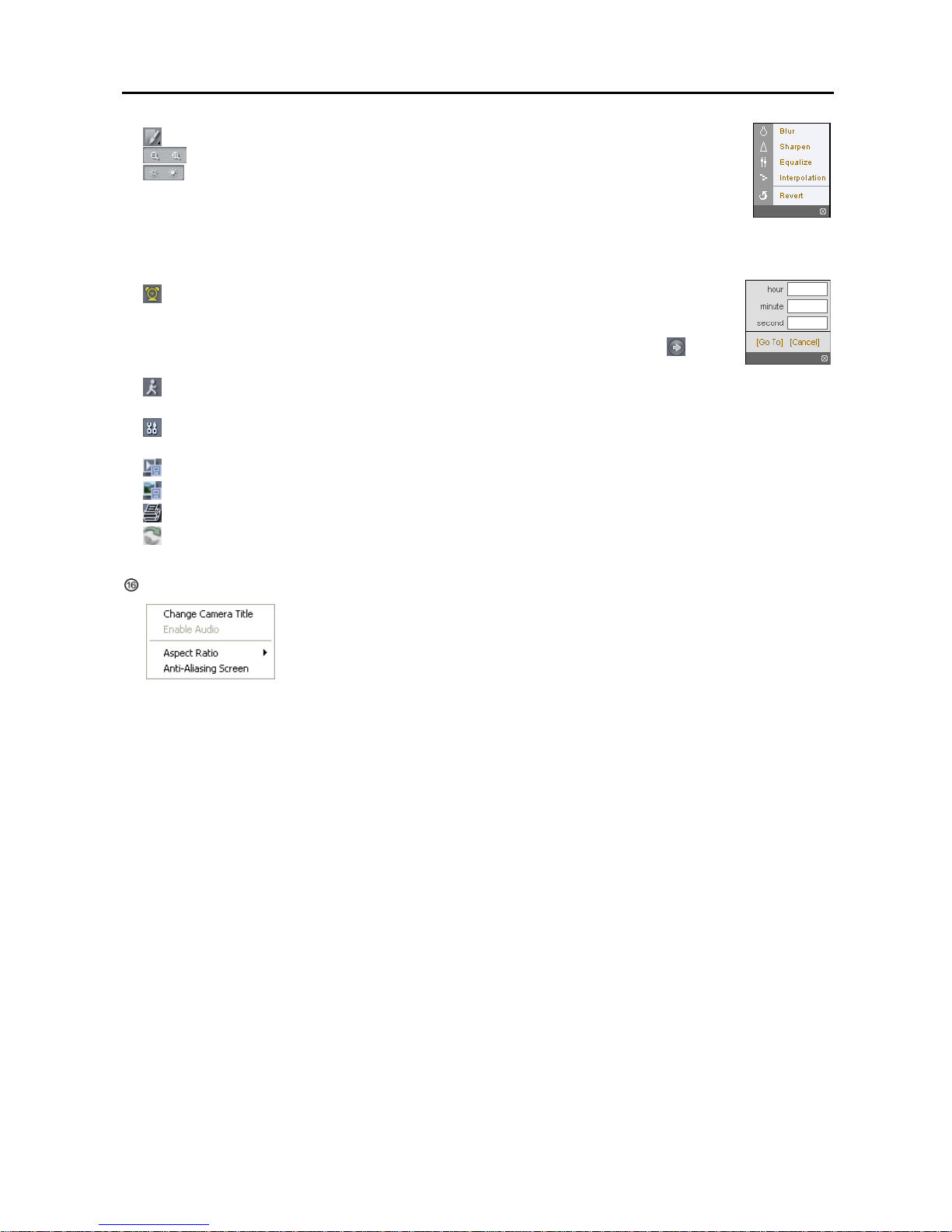
Digital Video Recorder
59
⑤ : Click to blur, sharpen, equalize and interpolate playback images.
: Click to zoom out or zooms in the recorded image.
: Click to adjust the brightness of the recorded images.
NOTE: Image processing works only in the pause mode.
⑥ The playback function buttons include fast backward, pause, play, fast forward, go to the first image, go to the previous
image, go to the next image, and got to the last image.
⑦ Click the screen format to select the desired display mode.
⑧
: Click to enter the time-lapse search mode which allows you to search for recorded data by
time and then play back images found within the time parameters. The Timetable window located
at the bottom displays the time information for the image of the date selected on the calendar.
Clicking a specific time displays the image recorded at that time on the screen. Selecting
allows
you to display an image from a specific time.
⑨
: Click to enter the event search mode which allows you to search for event log entries using specific conditions
and play back the images associated with those event entries.
⑩ : Click to set up the image drawing mode and OSD display. You can adjust the display speed by changing the
image drawing mode, and select OSD information to be displayed on the screen.
⑪ : Click to save any video clip of recorded data as an executable file.
⑫
: Click to save the current image in a bitmap or JPEG file format.
⑬
: Click to print the current image on a printer connected to your computer.
⑭
: Click to reload the recording data.
⑮ The Timetable displays recorded data of the selected camera by time (in hour segments).
Selecting a camera on the screen and clicking the right mouse button displays the text menu screen.
Change Camera Title: Changes the camera name.
Aspect Ratio: Changes the image aspect ratio.
Anti-Aliasing Screen: Enhances image display quality by eliminating stair stepping
(aliasing) effects in the enlarged image.
NOTE: A camera name change in the Web Search mode does not affect the camera name set up on the remote
site. Leaving the Camera Title blank causes the camera name set up on the remote site to display.
Page 66
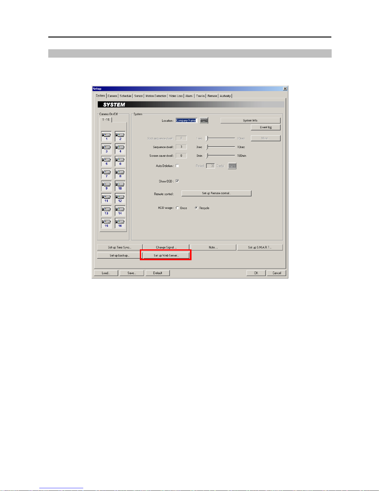
User’s Manual
60
Web Server Setup
The DVR includes a personal web server. If you do not want to run a web server, turn it off by clicking the Set up
Web Server... button under the System tab of the Setup dialog box in the SmartGuard mode and follow the instructions.
Page 67
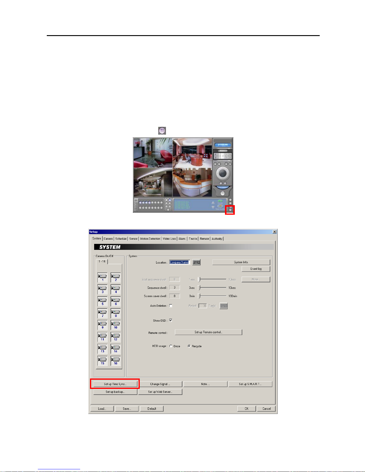
Digital Video Recorder
61
Appendix 5 — Time Synchronization
In general, each DVR system may have a different time because of the accuracy of its internal clock. The Time
Synchronization function synchronizes the time between POST systems and any time server when they are networked.
Any POST system or BASE system can run as a time server. Also you can use a standard time server provided by each
country.
NOTE: Visit http://www.eecis.udel.edu/~mills/ntp/clock1.htm for finding a standard time server.
NOTE: The BASE system cannot run as a time server in the Microsoft Windows Vista operating system.
1. Run the SmartGuard program and click the
(Setup) button on the main GUI.
2. Select the System tab.
Page 68
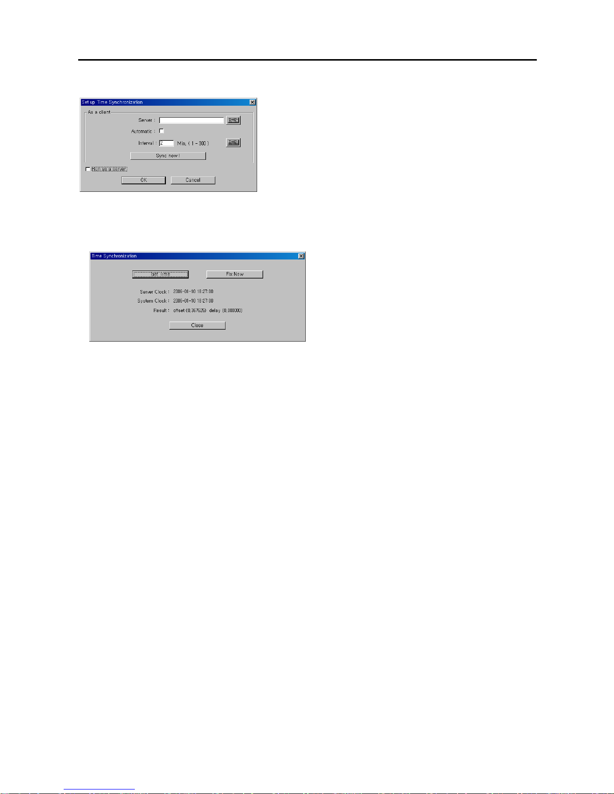
User’s Manual
62
3. Click the Set up Time Sync… button.
Server: Enter the IP address of target time server.
Automatic: Check the box if you want to synchronize the time
between the POST system and a time server automatically, and enter
the synchronization interval (1 to 300 minutes).
NOTE: When selecting Automatic (automatic time synchronization),
the system time will synchronize with the server time at a fixed time
every hour. If there is more than a 0.5 second gap between the
system and the server, the system time will be changed, and the
event will be recorded on the system log if there is more than a 1.0
second gap.
Sync now…: Click the button to synchronize the time manually.
Run as a server: Check the box if you want the DVR to run as a time server, and the Time Synchronization dialog
box appears.
− Get Time: Click the button to display the time
information of the target server.
− Fix Now: Click the button to change the system time
to the server time. If the server time is earlier than the
current DVR time, you must delete images dated later
than the server time. If you do not delete images, the
time cannot be reset.
NOTE: When setting up time synchronization for the first time, set the time between the system and the time server
manually because the system and the server might have wide time gap.
Page 69
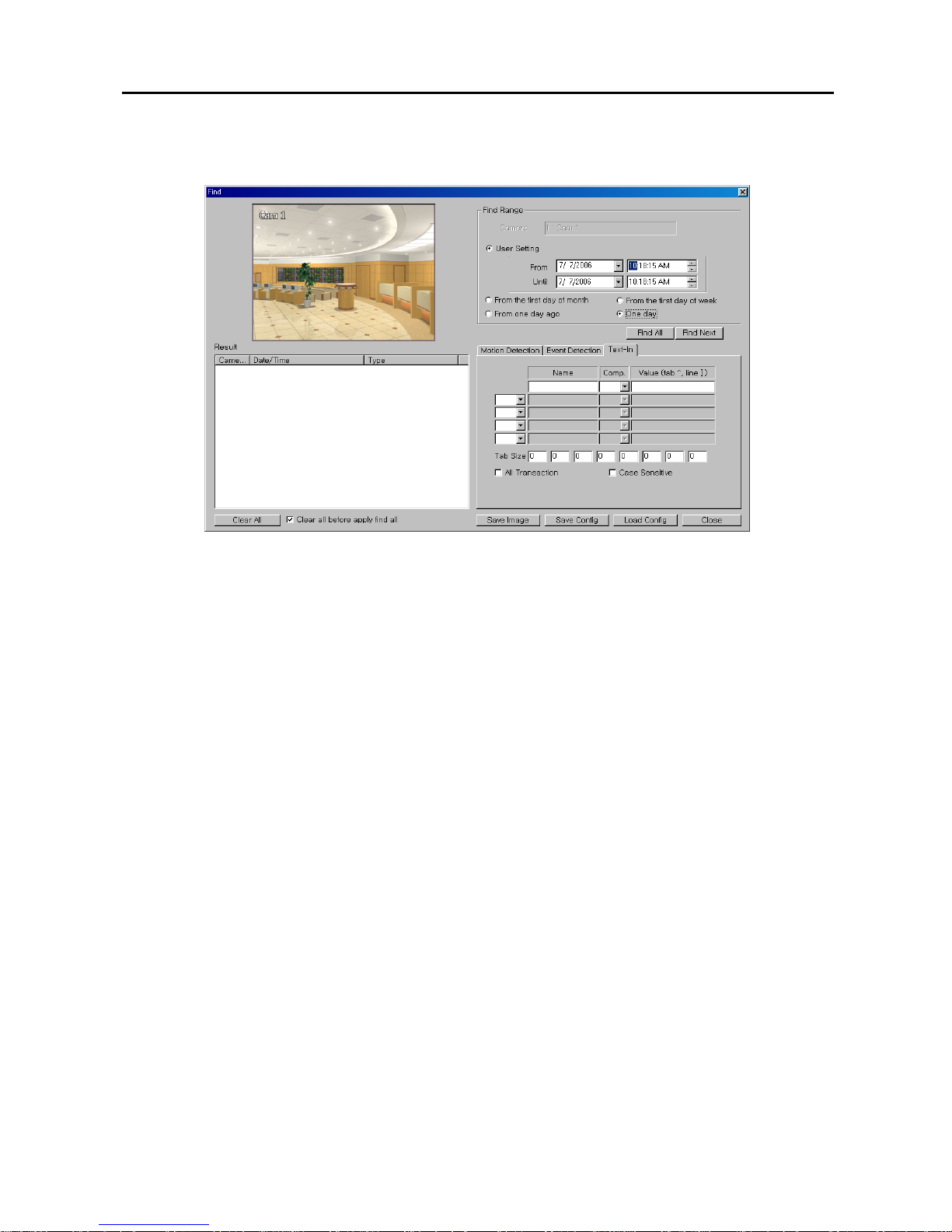
Digital Video Recorder
63
Appendix 6 — Text-In Query
Set up the find condition of text-in.
Name: Enter the text to find.
Comp: Enter the comparison operator.
Value: Enter the comparison value.
NOTE: The tab and line can be used for more specific search of the text-in data. Use a symbol ‘^’ indicating the
location of each individual category, and ‘]’ indicating the line where the category is located. See the following
examples for details.
Tab size: Enter the tab size. Up to eight tabs can be set.
All Transaction: Check this box to find all transaction results within established find conditions.
Case Sensitive: Check this box to distinguish between capital letter and small letters entered in the Name box.
Query Example I
1 2 3 4 5 6
123456789012345678901234567890123456789012345678901234567890
Item Unit price Qty amount
==================================================
Coke | $ 2.20 | 1(s) | $ 2.20
Fanta | $ 2.20 | 1(s) | $ 2.20
Hotdog | $ 3.50 | 3(s) | $ 10.50
Pepsi | $ 1.95 | 1(s) | $ 1.95
==================================================
total : $ 16.85
Thank you~~
Page 70

User’s Manual
64
In the above text-in data, you can find that the comparison value is located at 17th (Unit price, $ mark will be ignored
automatically), 28
th
(Qty) and 40th (amount) characters (including spaces) from the left. In this case, you can enter
“17”, “28” and “40” in each Tab size box, and enter the tab symbol “^” in the Value box (^ for Unit price, ^^ for Qty,
and ^^^ for amount).
For example, if you want to search for Coke with a Qty(Quantity) of more than 1 and Hotdog with an amount totaling
over $8, the following find condition can be set.
Coke > ^^1
and Hotdog > ^^^8
Query Example II
1 2 3 4 5 6
123456789012345678901234567890123456789012345678901234567890
Item Unit price Qty amount
==================================================
Coke | $ 2.20 | 1(s)
$ 2.20
Fanta | $ 2.20 | 1(s)
$ 2.20
Hotdog | $ 3.50 | 3(s)
$ 10.50
Pepsi | $ 1.95 | 1(s)
$ 1.95
==================================================
total : $ 16.85
Thank you~~
In the above text-in data, you can find that the comparison value is located at 17
th
(Unit price, $ mark will be ignored
automatically), 28th (Qty) and 40th (amount) characters (including spaces) from the left, but the value of amount category
is located at the different line from Item. In this case, you can enter “17”, “28” and “40” in each Tab size box, and
enter the tab symbol “^” and line symbol “]” in the Value box (^ for Unit price, ^^ for Qty, and ^^^ for amount / ] for
the next line).
For example, if you want to search for Coke with a Qty(Quantity) of more than 1 and Hotdog with an amount totaling
over $8, the following find condition can be set.
Coke > ^^1
and Hotdog > ]^^^8
Page 71
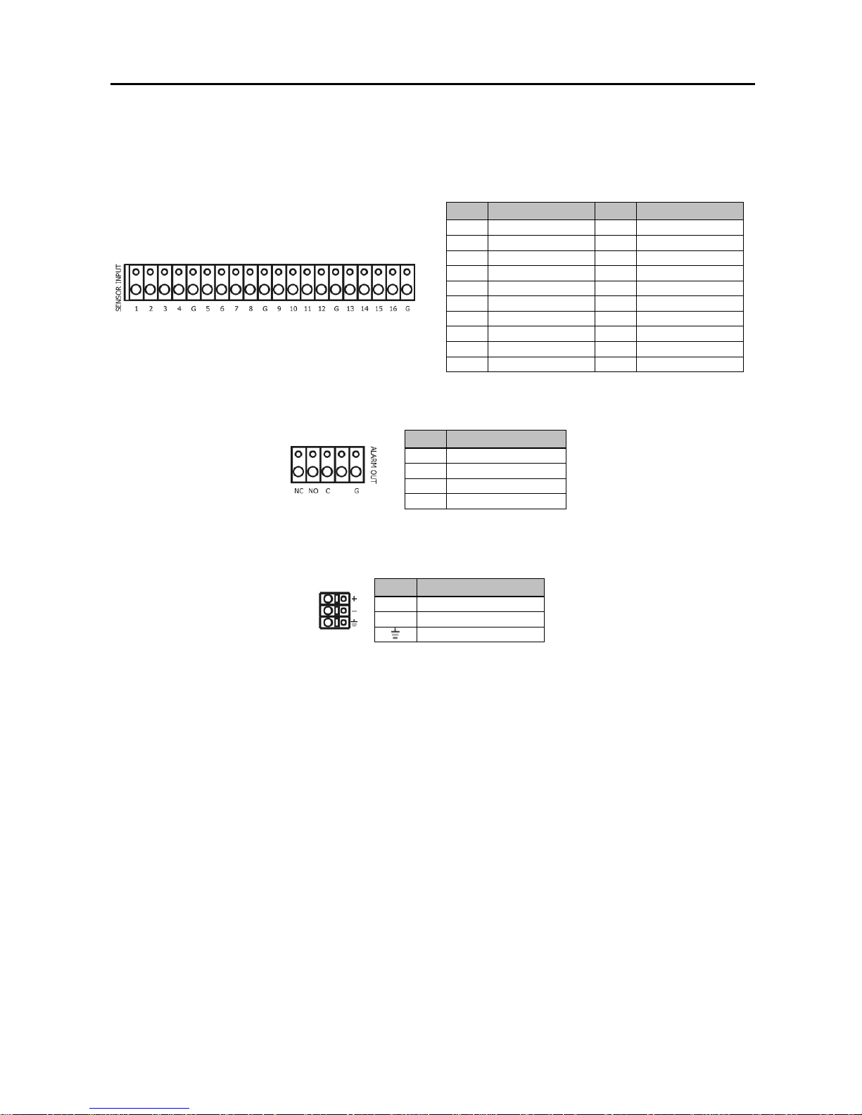
Digital Video Recorder
65
Appendix 7 — Connector Pin Outs
Sensor Input
No. Connector No. Connector
1 S1 (Sensor 1) 9 S9 (Sensor 9)
2 S2 (Sensor 2) 10 S10 (Sensor 10)
3 S3 (Sensor 3) 11 S11 (Sensor 11)
4 S4 (Sensor 4) 12 S12 (Sensor 12)
G GND (Ground) G GND (Ground)
5 S5 (Sensor 5) 13 S13 (Sensor 13)
6 S6 (Sensor 6) 14 S14 (Sensor 14)
7 S7 (Sensor 7) 15 S15 (Sensor 15)
8 S8 (Sensor 8) 16 S16 (Sensor 16)
G GND (Ground) G GND (Ground)
Alarm Output
No. Connector
NC NC (Normal Close)
NO NO (Normal Open)
C COM (Common)
G GND (Ground)
Remote Control Device (RS-485)
No. Connector
+
TRX+ (Send data)
–
TRX- (Receive data)
GND (Ground)
Page 72

User’s Manual
66
Appendix 8 — Event Log Notices
Start
Start Rec.
Stop Rec.
Begin Backup
End Backup
Sensor
Motion
Video Loss
Video On
Text-In
User ID : User Login Fail
User ID : Login Fail (3 times)
User ID login
User ID logout
[Remote] User ID login
[Remote] User ID logout
[Remote] User Login Fail
Stop saving image files, not enough disk space
HDD No. / HDD name
HDD No. / °C / Poor
HDD No. / °C / Good
Configuration file was broken, failed to load.
Warning: Rec. was stopped!!
Page 73
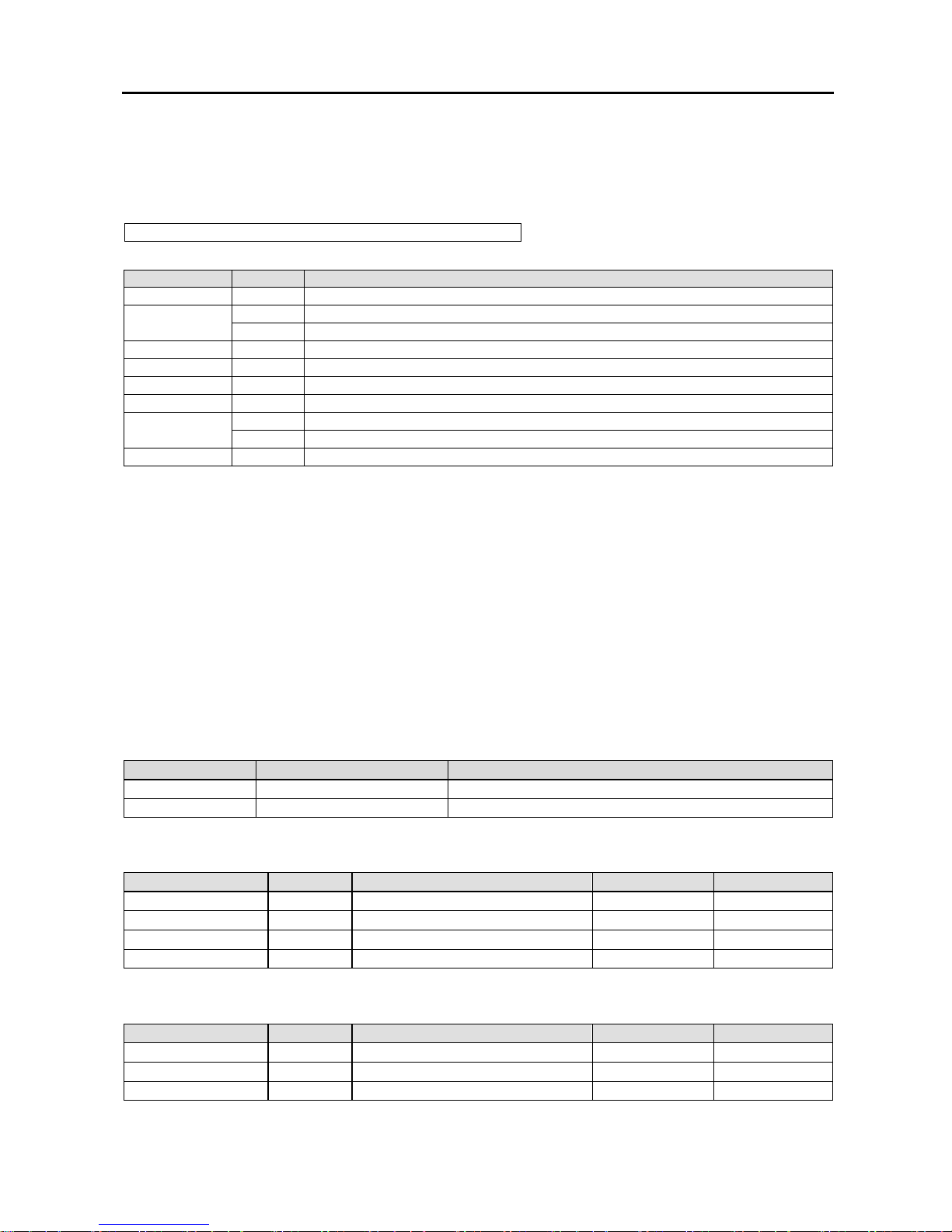
Digital Video Recorder
67
Appendix 9 — Protocol for Remote Controlling DVR
Message Format
<BOM><ID>:<Class>:<Code>[:Operands]:<Checksum>[EOM]
where
Symbol Value Description
: : Field delimiter
<BOM> @ Beginning of message (for command)
< Beginning of message (for reply)
<ID> 00~99 Device ID
<Class> DR Device Class (“DR” for DVR systems)
<Code> AA~zz Op-code (see below)
<Operands> Optional operands defined for each operation
<Checksum> 00~99 Checksum (sum of ASCII codes before checksum discarding overflow) i
* No checksum
[EOM] ^J^M End of message (optional: only for convenience of users using general terminal)
*All digits are used in decimal format.
*Example
buffer = “@01:DR:SF:0:”;
buffer + = checksum(buffer);
*Letters are case sensitive.
Control Flow
Every transaction consists of one command and one reply.
Characters transmitted before <BOM> are ignored.
The format of operands is defined independently for each op-code.
The <BOM> received before <Checksum> of the previous message resets interpretation: i.e., discards the previous
message. EXCEPTION: in case of text input, none of characters within specified length has special interpretation.
Common Reply
Reply code Reply data Description
ok
er 0000~9999 Error: return error number
General Functions
Function Code Operands ii Reply Reply data
Power Off PO
Time Setting TM YYYYMMDDHHMMSS
iii
LogIn LI 01~16:****:01~08:****iv
LogOut LO
v
Cursor Control
Function Code Operands Reply Reply data
Tab TB F/B(direction)
Enter EN
Text Input TI 01~99(length):string vi
Page 74
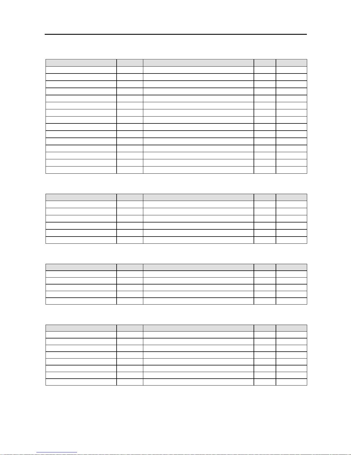
User’s Manual
68
Multiplexer (Display/Audio) Functions
Function Code Operands Reply Reply data
Screen Format SF 0~9
vii
Set Screen Format/Group FG 01~99
viii
(format):01~99(group)
Prev/Next Format NF -/+(prev/next)
Prev/Next Group NG -/+(prev/next)
Full Screen FS Y/N/T(on/off/toggle)
Camera Selection CS 00~99(camera)
Spot Camera SC 00~99(spot):00~99(camera)
Spot Sequence SS 00~99(spot):Y/N/T(on/off/toggle)
Sequence SQ Y/N/T(on/off/toggle)
Change OSD mode OS 0~9(mode) (0:off, 1:on)
Image Brightness IB +/0/-(direction):Y/N(step)
Image Contrast IC +/0/-(direction):Y/N(step)
Image Hue IH +/0/-(direction):Y/N(step)
Image Saturation IS +/0/-(direction):Y/N(step)
Image Default ID
Recorder (Player) Functions
Function Code Operands Reply Reply data
Recording On/Off RO Y/N/T(on/off/toggle)
Panic PN Y/N/T(on/off/toggle)
Playback PL F/B(direction):1~9(speed)
Playback (Still) PS A/Z/F/B/P/S
i
x
Screen Mode (Search) PM
Show Search PR
Alarm Functions
Function Code Operands Reply Reply data
Alarm Mute x AU 00~99/AA(id)
xi
:Y/N/T (on/off/toggle)
Alarm Out
xii
AO 00~99/AA(id)
Alarm Reset
xiii
AR 00~99/AA(id)
Alarm In AI 00~99/AA(id)
Reset Event-Recording RR 00~99/AA(id)
xiv
Telemetry Functions
Function Code Operands Reply Reply data
Pan & Tilt PT +/0/-(Pan dir.):+/0/-(Tilt):Y/N(step)
PTZ Preset PP 00~99(preset number)
PTZ Goto Preset PG 00~99(preset number)
PTZ Zoom PZ +/0/-(direction):Y/N(step)
PTZ Focus PF +/0/-(direction):Y/N(step)
PTZ Iris PI +/0/-(direction):Y/N(step)
PTZ Set Speed PX 01~16 (speed)
PTZ AutoPan PA Y/N
Page 75
Digital Video Recorder
69
Telemetry Extended Functions
Function Code Operands Reply Reply data
PTZ Select Camera PE 00:00~99 (camera number)
PTZ Pan Speedy Left PE 01:00~16(Speed 00 is “Stop”):Y/N(step)xv
PTZ Pan Speedy Right PE 02:00~16(Speed 00 is “Stop”):Y/N(step)
PTZ Tilt Speedy Up PE 03:00~16(Speed 00 is “Stop”):Y/N(step)
PTZ Tilt Speedy Down PE 04:00~16(Speed 00 is “Stop”):Y/N(step)
PTZ Zoom Speedy Tele PE 05:00~16(Speed 00 is “Stop”):Y/N(step)
PTZ Zoom Speedy Wide PE 06:00~16(Speed 00 is “Stop”):Y/N(step)
PTZ Focus Speedy Near PE 07:00~16(Speed 00 is “Stop”):Y/N(step)
PTZ Focus Speedy Far PE 08:00~16(Speed 00 is “Stop”):Y/N(step)
PTZ IRIS Speedy Close PE 09:00~16(Speed 00 is “Stop”):Y/N(step)
PTZ IRIS Speedy Open PE 10:00~16(Speed 00 is “Stop”):Y/N(step)
PTZ Power On/Off PE 50:Y/N/T (on/off/toggle)
PTZ Home Position PE 51
PTZ Auto Pan PE 52:00~16 (00 means “stop”)
PTZ Tour PE 53:00~16 (00 means “stop”)
PTZ Pattern PE 54:00~16 (00 means “stop”)
PTZ Menu On/Off PE 55:Y/N/T (on/off/toggle)
PTZ Alarm Reset PE 56
PTZ Alarm Out Control PE 57:00~99:Y/N/T(on/off/toggle)
PTZ Light On/Off PE 58:Y/N/T(on/off/toggle)
PTZ Pump On/Off PE 59:Y/N/T(on/off/toggle)
PTZ Wiper On/Off PE 60:Y/N/T(on/off/toggle)
PTZ Aux. On/Off PE 61:Y/N/T(on/off/toggle)
xvi
Getting Information from DVR
Function Code Operands Reply Reply data
Read Time tm tm YYYYMMDDHHMMSS
Read Alarm In ai ai 01~99:00…~FF… (alarm data)
Read Alarm Out ao ao 01~99:00…~FF… (alarm data)
Read Disk Usage du du 000~100
xv
ii
Read Recording ro ro Y/N
Read Panic Recording pr pr Y/N
Read Playback mode pm pm S/P/</>/R/F
xv
iii
Read Screen Format sf sf 0~9
Read Sequence sq sq Y/N
Error code
Error Code
Unclassified error 0000
Unsupported command 0001
Page 76

User’s Manual
70
Revision History
May 5, 2003 (Version 1.2)
– Added ss command for getting the status of system
– Added ao command for getting the status of alarm out
October 6, 2003 (Version 1.3)
– Added PX for specifying the speed at which PTZ moves
– Added PE for specifying the extended PTZ functions
November 5, 2003 (Version 1.4)
– Change SC, SS command to have 2 digit number for specifying spot monitor.
– Added PA for auto pan, which is different from PE:52 in PE:52 can specify the type of auto pan.
November 7, 2003 (Version 1.5)
– Add LI, LO, PM, PR commands.
July 22, 2008 (Version 1.6)
– Added FG, NF, NG command for 32ch control.
i
For DVR sample code for Checksum is followed.
int GetCheckSum(char *msg, int len)
{
DWORD sum = 0;
BYTE *p = (BYTE*)msg;
while (len > 0) {
sum += DWORD(*p++);
len--;
}
return int(sum%100);
}
void AddCheckSum(char* msg)
{
int len = strlen(msg);
int checksum = GetCheckSum(msg, len);
sprintf(msg+len, "%02d", checksum);
}
ii
Notation:
– (..): explanation only: do not include in the message.
– /: single selection from list of possible symbols.
– ~: for interval.
– …: the length is not fixed but determined by preceding operand
iii
Only 24hour format is supported: ex) 20000603135030
iv
Only support for Lan Control. ID can be up to 16 characters and password can be up to 8 characters.
v
Only support for Lan Control.
vi
The text can include special characters.
vii
Next(0), Full(1), 2x2(2), 3+4(3), 3x3(4), 2+8(5), 1+12(6), 4x4(7), PIP(8)
viii
1(full), 2(2x2), 3(3+4), 4(3x3), 5(2+8), 6(1+12), 7(4x4), 8(PIP), 9, 10(Not used on IDR), 11(5x5), 12(1+32)
ix
A/Z/F/B/P/S: first, last, forward, backward, pause, stop
x
Alarm Mute : alarm out is off while Alarm Mute is on regardless of alarm status
xi
00~99/AA(id) : 00~99 for each alarm, or AA for all alarms
xii
Alarm Out: generate alarm out, which is automatically turned off after the programmed dwell time
xiii
Alarm Reset: clear alarm out
xiv
Reset Event-Recording: resets event-driven recording associated with alarm-in of the given id.
xv
00 means stop, 01 is the minimum speed and 16 is the maximum speed. All stop commands of left, right, up, down by this
speed operand call same internal function of DVR – ‘MovingStop’.
xvi
Turn on or off the auxiliary function supported the PTZ or Dome.
xvii
Percentage
xviii
S/P/</>/R/F : stop/pause/backward playback/forward playback/rewind/fast forward
Page 77

Digital Video Recorder
71
Appendix 10 — Troubleshooting
Following are some frequent problems and solutions related to the DVR. Read this section before calling the dealer
or installer.
Problem: There is no image on the screen.
Solution: Check the camera cables. If the background of the DVR system is blue, something is wrong with the camera
cable or power.
Problem: How do I access Windows?
Solution: To protect unnecessary system crashes, Windows is blocked. See Appendix 1 — Accessing Windows.
Problem: I have upgraded the software. How do I reinstall it?
Solution: There are three steps to reinstall the software.
1. Uninstall the old version.
– Go to My Computer. Select Control Panels and the Add/Delete program, and then select the DVR model.
– The Delete button will be activated. Click Delete.
2. Scan the hard disk with the System tools under Programs/Accessories in Windows.
3. Install the new software.
Problem: The IDIS logo appears and then freezes. Sometimes the screen is black.
Solution: There is a problem with the Main Board. Reboot the DVR. If it happens often, call your dealer or installer.
Problem: The Display setup is not correct error message appears and opens up in the Windows mode
when OK is clicked.
Solution: The DVR requires 1024x768 resolution and true color. This message will be printed on the screen when
the requirements are not met. Access Display Setup and change the values for the DVR and then reboot the system.
Problem: I am trying to change the display setup, but I cannot choose True color. The resolution
keeps jumping to a lower value.
Solution: Some VGA cards require a few steps. Set up the resolution first. Do not worry about the color palette. Then
access Display Setup and choose True color. If it happens again, the VGA card does not support the 1024x768 resolution
and True color. Change the VGA card.
Problem: The USB-serial converter has been connected to the DVR for the POS installation, however,
the dialog box asking the device driver appears.
Solution: When connecting the POS device to the DVR using the USB-serial converter, connect the converter while
the DVR is operating. If not, the converter driver may not be operating properly and display the dialog box asking
the device driver during the system boot. However, it does not have any effect on the DVR operation. Remove the
converter, and reboot the DVR and then connect the converter again.
Page 78
User’s Manual
V2.8
72
Appendix 11 — Specifications
VIDEO
Signal Format NTSC or PAL (programmable)
Video Input Composite: 16 inputs, 1 Vp-p, 75 Ohms termination)
Monitor Outputs
Composite: One, 1 Vp-p, 75 Ohms
S-Video: One, 1 Vp-p, 75 Ohms (PDR16-PC-RT model only)
VGA
: One
Recording Resolution
PDR16-PC model: 640x480, 640x240, 320x240, 160x120
PDR16-PC-RT model: 704x480, 704x240, 352x240, 176x120
(704x576, 704x288, 352x288, 176x144 for PAL)
Display / Record Speed
(images per second)
PDR16-PC model: max. 120ips / 120ips (100ips / 100ips for PAL)
PDR16-PC-RT model: max. 480ips / 480ips (400ips / 400ips for PAL)
INPUTS/OUTPUTS
Alarm Input 16 TTL, NC/NO programmable
Alarm Output 1 relay, 1A@5V
Audio Input One, “line in” or “mic” programmable
Audio Output One, “line”
CONNECTORS
Video Input Composite: 16 BNC
Monitor Output
Composite: 1 BNC
S-Videoi: 1, 4-Pin Mini DIN (PDR16-PC-RT model only)
VGA
: 1 VGA
Audio In Line in or microphone
Audio Out Line out
Alarms Terminal block
Ethernet Port
ii
RJ-45
RS232 Serial Port DB9 (P)
RS485 Serial Port Terminal block on the extension card
USB Port 6 USB connectors
Parallel Port 25 (P) D-Sub
STORAGE
Primary Storage
SATA hard disk drive (Expandable up to 3 with 2 EIDE and 1 SATA hard disk drives
or with 3 SATA hard disk drives)
Secondary Storage USB hard disk drives
Backup Storage CD-RW or DVD RW
GENERAL
Dimensions (W x H x D) 17.3" x 7.0" x 18.9" (440mm x 177mm x 462mm)
Unit Weight 28.0 lbs. (12.7kg)
Shipping Weight 38.4 lbs. (17.4kg)
Shipping Dimensions
(W x H x D)
23.2" x 13.8" x 27.6" (590mm x 350mm x 700mm)
Operating Temperature 41°F to 104°F (5°C to 40°C)
Operating Humidity 0% to 90%
Power AC 100-240V~, 50/60 Hz, 3.0-1.5A
Approvals FCC, CE, UL
iii
i
Direct connection of a cable longer than three meters may result in noisy video image.
ii
The network connector is not designed to be connected directly with cable or wire intended for outdoor use.
iii
CAUTION: Risk of Explosion if Battery is replaced by an Incorrect Type. Dispose of Used Batteries According to the Instructions. This
equipment is indoor use and all the communication wiring are limited to inside of the building.
Specifications are subject to change without notice.
 Loading...