

Page 1
PAC-C-EB20IRVF-2.8-12-GY
PAC-C-EB20IRVF-2.8-12-WH
Vandalproof IR Dome Camera
User Manual
Issue
V1.0
Page 2
Introduction
This Vandalproof IR dome camera has state of the art technology to give the very
best image quality. It meets the demands of new age camera technology in the
CCTV market, with both Analog SD and HD Camera applications.
Guide
Model Features:
· 2.0 Megapixel HD camera
· 500 Meter Coaxial cable distance
· Programmable AE/AWB/AF detection
· 3D-NR(Noise Reduction)
· Defog DWDR
· Dead pixel compensation(live/static)
· User defined OSD
· HD Technology
· 1/3”2.0MP CMOS
· Up To 500 Meters
· 3D DNR
· BNC Video Output
· Dual Voltage DC12V/AC24V Operation
· IR LED for Night Vision
· True Day/Night ICR
■ WARNING !
To avoid electrical shock, do not open the casing. Refer servicing to qualified
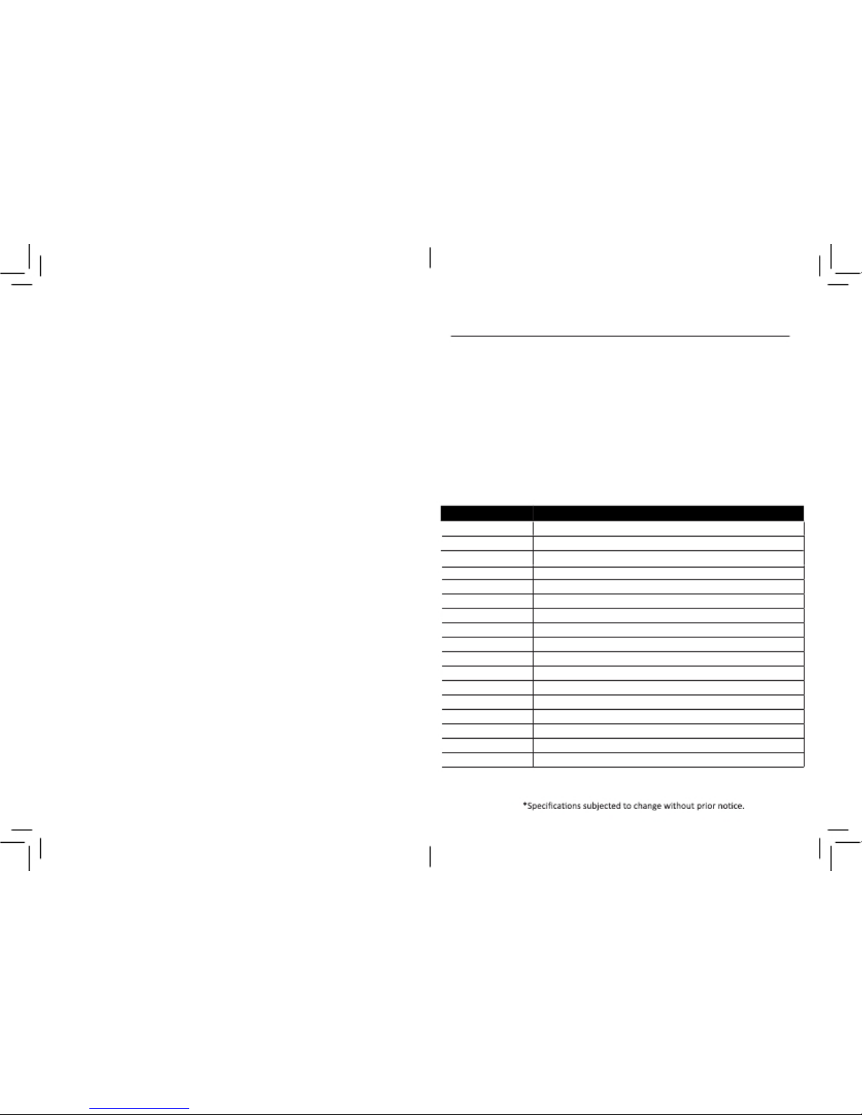
Solution General Specifications
personnel only.
General
■ NOTE !
Model
PAC-C-EB20IRVF-2.8-12-GY
PAC-C-EB20IRVF-2.8-12-WH
Before Use
1. Do not lift the camera by only holding the cables.
Operating or Storage Location
Avoid operating or storing the camera in the following locations:
1. Extremely hot or cold places(o peratin g tem per atur e : -20°C to +55°C).
2. Close to heating equipment (e.g., near heaters)
3. Close to sources of strong magnetism.
4. Close to sources of powerful electromagnetic radiation, such as radios or
TV transmitters.
5. Locations subject to strong vibration or shock.
6. Locations subject to steam or high humidity.
7. Locations subject to strong wind ,such as high places.
8. Locations where corrosive gas or flammable gas is emitted, or where salt
damage may occur.
9. Location subject to condensation and high humidity.
1O. Location subject to soot or oil stains.
■ Camera setting
Don't touch the PCB Board by hand directly .
■ Ventilation
IR LED
Resolution
Min. Illumination
Lens
Lens mount
ACG / BLC
WB
Sync System
E-Shutter
Video output
S/N Ratio
Video output
Ingress
Power Consumption
Operating temperature
Operating humidity
15 pcs IR LED(distance = 15m)
2MP(1920X1080@ 25fps)
0.01 Lux@F1.2(AGC On),0 Lux IR LED On
Varifocal 2.8-12 mm Lens models
Fixed mount
Auto
AWB
Internal
1/25s~1/500,000s
1 channel SD or HD video output
More than 48dB (AGC OFF)
BNC Connector
IP66
DC 12V/AC 24V, Max 4.5W
-20°C ~ +55°
0-90% (non-condensing)
1
To prevent heat buildup, do not block air circulation around the camera
2
Page 3
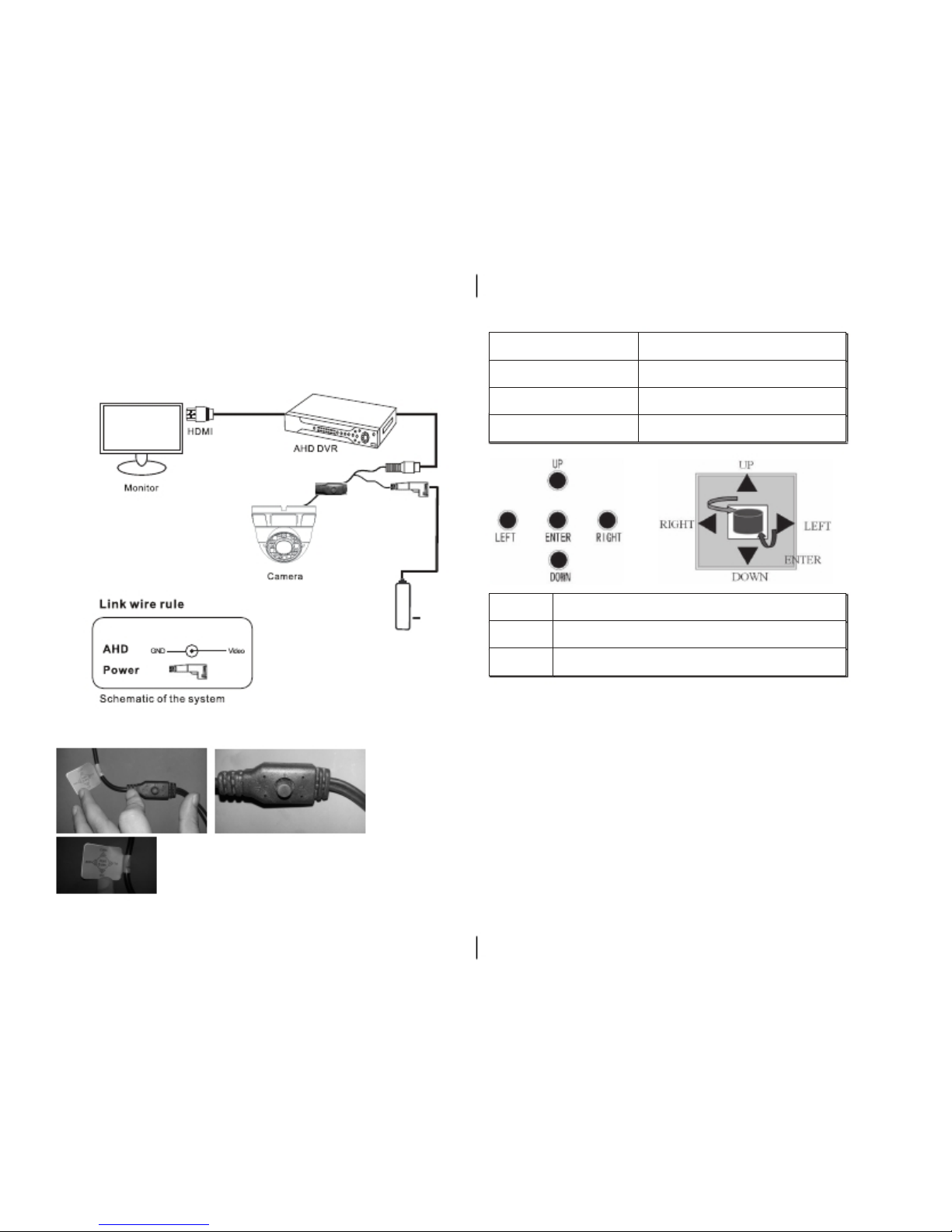
Push UP for 5 seconds
The camera will output with the Analog signal
Push DOWN for 5 seconds
The camera will output with the HD-CVI signal
Push LEFT for 5 seconds
The camera will output with the HD-AHD signal
Push RIGHT for 5 seconds
The camera will output with the HD-TVI signal
ENTER Push down onto the joystick to use Enter function.
UP/DOWN Push the joystick up and down.
LEFT/RIGHT
Push the joystick left or right to modify the menu,parameters. Push right again
to enter into the next menu option.
Introduction
Schematic of the System
BNC Output
3
OSD Menu Function
OSD Menu
DC 12V/AC 24V
4
Page 4

,
OSD
Method 1. Press the "Enter" key to display the main menu. The main menu
will disappear if no further commands are made after 30 seconds.
(1)Electronic Shutter:User can set both slow and high-speed shutter.( The
speed can be set as auto, from 1 / 25 ~ 1 / 500000, FLKX2~X30. The user
can set the specific speed according to the specific surroundings. The default
value is auto. )
(2)AGC:This function not only increases the brightness of camera images,
but also increases the image noise, in accordance to the surroundings.
Adjustable limites are 0-15.
(3)Sens-Up
(4)Brightness: 0~100 adjustable.
(5)D-WDR:Digital Wide Dynamic Range:Off/On,if turned on, adjustable level are 0-8
(6)Defog:In foggy weather,you can setup this function to see the object
behind fog.choose Auto to adjust position/size.
(7)Return
Back Light Compensation
(1)BLC
Lens
DC/Manual -Camera is set to Manual due to lens type
Exposure
(2)HSBLC
5
6
Page 5

NR
Switch to Hight/Middle/Low and OFF to enable or disable noise reduction on dynamic
recordings.
White Balance
Is used to restore the authenticity of the color affected by the change of color
temperature.
White balance options include:
Manual/AWB/ATW/AWC/Indoor/Outdoor.
Special
Day&Night
The Day & Night Switch is specifically designed for different surroundings.
There are 3 kinds of modes as follows:
EXT mode, Auto mode, Color mode, B/W mode
(1)D&N EXT
( 1 )Cam Title
( 2 )D-Effect
(2) D&N Auto
(a)Freeze:On/Off.
7
(3) Color Mode:Always Color
(4) B/W Mode:Always Black and White
(b)Mirror:Mirror/V-Flip/Rotate/Off.
(c)Neg_Image:On/Off.
(d)Return
8
Page 6

( 3 )Motion:Select motion areas,Display,Sensitivity,Color,Trans,Alarm.
1.Sharpness:Auto/Off.
2.Monitor:LCD/CRT.
3.LSC:Off/On.
4.Video.Out:PAL/NTSC
5.Return
Exit
When all settings are complete, press "Up", "Down" to move the cursor to "Exit", select
"Save&End "(save the changes of parameters and then exit the menu) or "Reset" (
recovers factory settings ) or "Not Saved"(Doesn't save the settings and exits the
menu).
(4)Privacy:Select privacy areas,Display,Color,Trans.
(5) Language
Simplified Chinese,traditional Chinese,Germany,French,Italian,Spanish,Polish,
Russian, Portuguese,Turkish.
(6) Defect:Press to select the DPC(Defective Pixel Correction)level of defect.
Please do not use this function without covering the lens.
(7)Return
Adjust
9
10
Page 7

Installation
Mechanical Drawing Installation Information(General Overview
1
3
2
4
Accessories
1 Open package, take out the camera, unscrew the camera compression ring,
and disassemble the camer a .
Wall Mount Bracket
S84187 PAC-BK323-WH
S84188 PAC-BK323-GY
Universal Junction Box(Options)
S46544 PAC-JB-EYEBALL
(Not Included)
2 Drill mounting holes on the ceiling or wall, using the camera mounting base
as a template. Also drill a cable entry hole as required to suit the position.
of the camera. Figure 1 shows the dimension of the camera mounting base.
3 Install the plastic inserts in to the drilled holes, and fix the camera mounting base
to the ceiling (or wall) by use of self-tapping screws.
4
Install the compression ring, the dome shell, and the dome shell fixed base on
the camera mounting base. Figure 2 shows camera installation.
5 Turn the main body, adjust the lens direction, and note the position
NOTE:Make sure youdon’t have any missing parts before you make the installation.
Incorrect installation could void the warranty if instructions are not followed correctly.
Please call technical for assistance if you are unsure about any procedures.
11
of the dome cover window.
6 Adjust view angle and focal length by using the adjusting tool, as shown in Figure 4.
12
Page 8

13
Trouble and Solution
1.No picture after connecting the camera?
Please check the power supply to ensure power is connected. Also check that
all associated connections e.g connection to the monitor are firmly pushed in.
2. Picture distortion. Eliminate interference by possibly filtering the power supply.
NOTES
14
 Loading...