


00
GIGABIT
LAN EXPANSION MODULE
P/N 20-0162-03 Rev B

DISCLAIMER
THIS MANUAL IS PROVIDED "AS IS" WITHOUT ANY EXPRESS OR
IMPLIED WARRANTY OF ANY KIND INCLUDING WARRANTIES OF
MERCHANTABILITY, NONINFRINGEMENT OF INTELLECTUAL
PROPERTY, OR FITNESS FOR ANY PARTICULAR PURPOSE. IN NO EVENT
SHALL PACKETEER, INC. OR ITS SUPPLIERS BE LIABLE FOR ANY
DAMAGES WHATSOEVER (INCLUDING, WITHOUT LIMITATION,
DAMAGES FOR LOSS OF PROFITS, BUSINESS INTERRUPTION, LOSS OF
INFORMATION) ARISING OUT OF THE USE OF OR INABILITY TO USE THIS
MANUAL, EVEN IF PACKETEER, INC. HAS BEEN ADVISED OF THE
POSSIBILITY OF SUCH DAMAGES. BECAUSE SOME JURISDICTIONS
PROHIBIT THE EXCLUSION OR LIMITATION OF LIABILITY FOR
CONSEQUENTIAL OR INCIDENTAL DAMAGES, THE ABOVE LIMITATION
MAY NOT APPLY TO YOU. Packeteer, Inc. and its suppliers further do not warrant
the accuracy or completeness of the information, text, graphics, links or other items
contained within this manual or for incidental, indirect, special or consequential
damages in connection with the furnishing, and performance of this manual.
Packeteer, Inc. may make changes to this manual, or to the products described herein,
at any time without notice. Packeteer, Inc. makes no commitment to update this
manual. You may not use or export this document in violation of U.S. export laws and
regulations.
COPYRIGHT/TRADEMARKS
Packeteer, the Packeteer logo, combinations of Packeteer and the Packeteer logo as
well as PacketShaper and PacketSeeker are trademarks or registered trademarks of
Packeteer, Inc. in the United States and other countries. Other product and company
names used in this document are used for identification purposes only and may be
trademarks of other companies and are the property of their respective owners.
Copyright © 1996 - 2006 Packeteer, Inc. All rights reserved. No part of this document
may be reproduced, photocopied, stored on a retrieval system, transmitted, or
translated into another language without the express written consent of Packeteer, Inc.
U.S. GOVERNMENT RESTRICTED RIGHTS
The Packeteer Software is comprised of "commercial computer software" and
"commercial computer software documentation" as such terms are used in 48 C.F.R.
12.212 (SEPT 1995) and is provided to the Government (i) for acquisition by or on
behalf of civilian agencies, consistent with the policy set forth in 48 C.F.R. 12.212; or
(ii) for acquisition by or on behalf of units of the Department of Defense, consistent
with the policies set forth in 48 C.F.R. 227-7202-1 (JUN 1995) and 227.7202-3 (JUN
1995). Packeteer, Inc. software is provided with "RESTRICTED RIGHTS." Use,
duplication, or disclosure by the Government is subject to restrictions as set forth in
FAR 52.227-14 and DFAR 252.227-7013 et seq. or its successor. Use of Packeteer,
Inc. products or software by the Government constitutes acknowledgment of
Packeteer Inc.'s proprietary rights in them and to the maximum extent possible under
federal law, the Government shall be bound by the terms and conditions set forth in
Packeteer, Inc.'s end user agreement.
Packeteer®, Inc.
10201 North De Anza Drive, Cupertino, CA 95014
http://www.packeteer.com
PRINTING HISTORY
October, 2006 20-0162-03 Revision B
SAFETY AND REGULATORY COMPLIANCE
For information on safety and regulatory compliance, see "Safety and Regulatory
Information" in Appendix A.

TABLE OF CONTENTS
Chapter 1: When to Use a LAN Expansion Module
Gigabit LAN Expansion Module Requirements ................................ 1-2
Installing a Gigabit LAN Expansion Module .....................................1-3
Chapter 2: Install into a 6500 Model
Installing the LEM ..............................................................................2-2
Verify the Installation..........................................................................2-7
Configure the LEM module ................................................................2-8
Connect the Unit to a Router.............................................................2-9
Managing Traffic with Three LANs ............................................... 2-12
Problems?..........................................................................................2-13
Chapter 3: Install into a 8500/9500/10000 Model
Installing the LEM ..............................................................................3-2
Verify the Installation..........................................................................3-6
Configure the LEM module ................................................................3-7
Connect the Unit to a Router...............................................................3-8
Managing Traffic with Three LANs .................................................3-11
Problems?..........................................................................................3-12
Appendix A: Safety and Regulatory Information


1-1
CHAPTER 1: WHEN TO USE A LAN EXPANSION MODULE
Packeteer’s PacketShaper, PacketSeeker and AppVantage
offer visibility into network application performance and the
ability to control it when needed. They monitor and manage
traffic at WAN access links, ensuring a smooth flow that
maximizes throughput and speeds critical traffic. A
LEM2-1000M-T and LEM2G-1000M-T LAN Expansion
Module extends these benefits to topologies that incorporate
multiple LANs.
The following scenarios are examples of situations that
require a Lan Expansion Module:
• You want to manage a single WAN link and your
network includes a firewall/router that splits your
network into two separate LANs: a protected segment
and a DMZ segment.
• You want to manage a single WAN link and your
network includes a router with multiple LAN
segments.
• You have a single WAN link and your network
includes a router with two LANs; one segment may
connect to the LAN through a firewall and the other to
a VPN tunnel management device.
• Your network includes branch offices with two or
three separate LANs that you manage, and only one
WAN link.

Chapter 1: Introduction
1-2
Gigabit LAN Expansion Module Requirements
The software for the LEM2-1000M-T Gigabit LAN Expansion
Module is included in PacketWise version 6.1.0 and all later
versions. The RoHs-compliant LEM2G-1000M-T requires
PacketWise 7.x or later.
✍ Note: The PacketShaper 10000, PacketSeeker 10000 and
PacketShaper/ISP 10000 are only compatible with LEM2G1000M-T and later-generation LEM2-1000M-T LAN
Expansion Modules. These newer LEM2-1000M-T LEMs
can be identified by their serial numbers, which have values
of 006-10010001 or higher. For details, see “Problems?” on
page 3-12.
LANs connected to this copper-connector LEM module must use
10BaseT, 100BaseT, or 1000BaseT RJ-45 Ethernet ports or use
fiber optic conversion units for fiber optic networks.
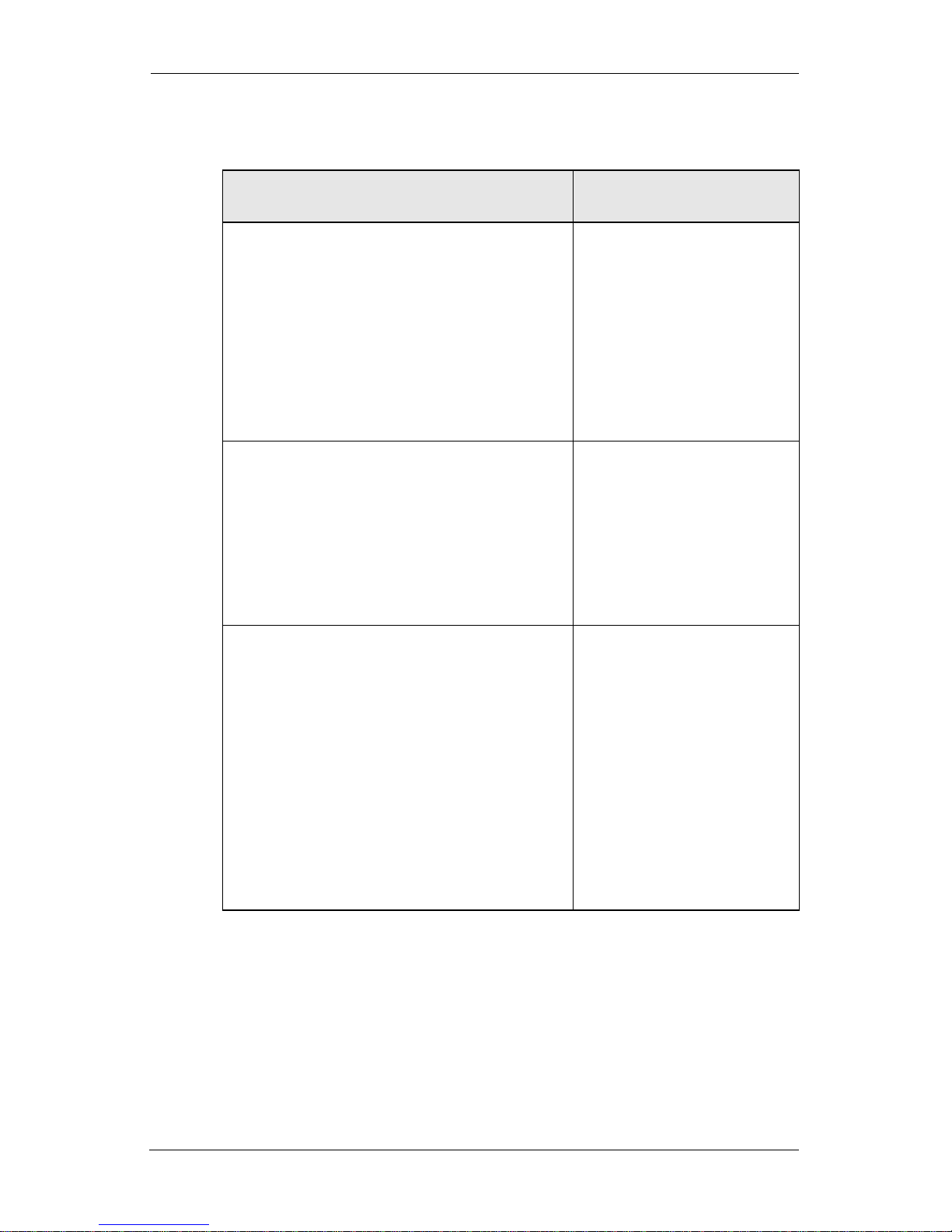
LED
Indicators
The front panel of the LEM has the following LED indicators
beside each port.
LED
Indicator
Description
Link Illuminated when the network cable is
properly connected
Tx/Rx Illuminated when network cable is properly
connected; flickers when the unit is
transmitting and receiving data
Speed When properly installed, the speed LED
color on the LEM module indicates that the
LEM is operating at the following speeds:
• amber = 1GB
• green = 100MB
•off = 10MB

Chapter 1: Introduction
1-3
Installing a Gigabit LAN Expansion Module
The connectors on your Packeteer unit look like one of the four
illustrations below. Follow the instructions that match your unit.
If your unit looks like this, follow the installation directions in
Chapter 2, "Install into a 6500 Model."
If your unit looks either one of these, follow the installation
directions in Chapter 3, "Install into a 8500/9500/10000 Model."
FAULT
POWER
STATUS
Tx/Rx
100
LINK
Tx/Rx
100
OUTSIDEINSIDE
LINK
CONSOLE
FAULT
POWER
STATUS
CONSOLE
INSIDE OUTSIDE
LINK
Tx/Rx
SPEED
LINK
Tx/Rx
SPEED
FAULT
POWER
STATUS
CONSOLE
OUTSIDE
INSIDE OUTSIDE
LINK
Tx
Rx
LINK
Tx
Rx
FAULT
POWER
STATUS
CONSOLE
OUTSIDE
INSIDE OUTSIDE
LINK
Tx
Rx
LINK
Tx
Rx
BYPASS CTRL
INSIDE
OUTSIDE
SX/LX
Tx/Rx
Link
SX/LX
Tx/Rx
Link

Chapter 1: Introduction
1-4

Chapter 2: Install into a 6500 Model
2-1
CHAPTER 2: INSTALL INTO A 6500 MODEL
This chapter describes how to install a LEM2G-1000M-T or LEM21000M-T Gigabit LAN Expansion Module (LEM) into
PacketShaper 6500, PacketShaper 6500/ISP, or
PacketSeeker 6500. The directions in this chapter apply only to
these models, which are hereafter collectively referred to as a
“6500 model.”
The following illustration shows a unit with two LEMs installed,
for a total of three LANs using one 6500 model. This is a maximum
configuration; you can install only one module if you wish.
Directions begin on the next page.
FAULT
POWER
STATUS
Tx/Rx
100
LINK
Tx/Rx
100
OUTSIDE
INSIDE
LINK
CONSOLE
WAN Router
INPUT
100-240 MAX
50-60Hz
INSIDE OUTSIDE
INSIDE OUTSIDE
LAN B
LAN C
LAN A
WAN
LINK
Tx/Rx
SPEED
LINK
Tx/Rx
SPEED
LINK
Tx/Rx
SPEED
LINK
Tx/Rx
SPEED

Chapter 2: Install into a 6500 Model
2-2
Installing
the LEM
To install the LEM into a 6500 model:
1. Disconnect the system from any telecommunication links,
networks, or modems, and then turn off the system power
source. WA RN IN G: Failure to do so before you open the
system or do any procedures can result in personal injury or
equipment damage.
2. Ground yourself. WAR NI NG : Electrostatic discharge
(ESD) can damage system components. If an ESD station is
not available, wear a wrist strap attached to a metal part of
the system. If you don’t have a strap, touch some metal part
of the box to ground yourself.
3. Remove the rackmount ears (if present) from the 6500
model, then remove the screws from the back of the unit.

Chapter 2: Install into a 6500 Model
2-3
4. Remove the unit cover.
5. Remove the screw that holds one of the slot covers in place.
To install two modules, remove both slot covers.
INSIDE OUTSIDE

Chapter 2: Install into a 6500 Model
2-4
6. Remove the screws holding the C-shaped mounting bracket
from the module, then remove the bracket.
7. Attach the other bracket supplied with the LEM by aligning
the screw holes on the bracket tabs directly above the screw
holes on the module, then inserting the screws from below.
WA RN IN G: Using an incorrect bracket can damage the
module or the 6500 model.
SPEED
Tx/Rx
LINK
SPEED
Tx/Rx
LINK
OUTSIDE
10/100/1000MB
Ethernet
INSIDE
SPEED
Tx/Rx
LINK
OUTSIDE
INSIDE
SPEED
Tx/Rx
LINK

Chapter 2: Install into a 6500 Model
2-5
8. If the unit is or will be using the standby function, remove
the jumpers from the module as shown below.
✍ Note: Do not discard the jumpers; you will have to replace
them if you later wish to disable the standby function. For
additional information on enabling or disabling standby, refer
to the latest Getting Started Guide for your Packeteer unit,
available at http://support.packeteer.com/documentation.
9. Locate the expansion slots on the riser card in the interior of
the 6500 model.
LINK
Tx/Rx
SPEED
Tx/Rx
LINK
OUTSIDE
10/100/1000MB
Ethernet
INSIDE
SPEED
Tx/Rx
LINK
OUTSIDE

Chapter 2: Install into a 6500 Model
2-6
10.Insert the LEM completely into the opening, then push it
toward the expansion slots on the riser card until it snaps
into the slots. Be careful not to push the riser card so hard
that it disconnects from the motherboard. Note that there are
extra pins on the LEM that are not used on a 6500 model.
These extra pins will not attach to the riser card.
11.If you are installing two LEMs, repeat steps 6-10 for the
other module.
12.Replace the screw(s) that holds the expansion card(s) in
place, then replace the cover and cover screws.
SPEED
Tx/Rx
LINK
SPEED
Tx/Rx
LINK
OUTSIDE
INSIDE

Chapter 2: Install into a 6500 Model
2-7
Verify the Installation
Access the unit’s browser interface and check the setup tab to be
sure your card has been recognized by the system. It should look
something like the one below.
From the setup page, select one of the following NIC modes for
each LEM interface: 10BaseT half-duplex, 10BaseT full-duplex,
100BaseT half-duplex, 100BaseT full-duplex, 1000BaseT fullduplex. Auto-negotiate is the default network communication
selection.
✍ Note: Selecting 1000BaseT full-duplex causes the unit to
auto-negotiate per IEEE standard.
The screen above indicates that the built-in LEM card for this unit
is 100 Megabits, the lower slot contains a 100 Megabit LEM, and
the upper slot contains a Gigabit LEM.

Chapter 2: Install into a 6500 Model
2-8
Configure the LEM module
1. From the web browser interface, click the setup tab, then
choose the basic setup page. Set Site Router to none. If this
is set incorrectly, you may not be able to use the LEM.
2. To check security on this unit, select the setup tab, then
choose security from the drop-down box. The Outside and
Inside interface settings also apply to the LEM interfaces.
3. You can change security settings for all Inside and Outside
interface communication, if desired. Click the
Inside Interfaces: and Outside Interfaces: drop-down lists
to set access to all, none, or specified devices.
Setting Access Level
unsecure
(default)
Enables unlimited access over the specified
interface
secure Blocks all access from the specified interface
list Enables access to up to eight listed IP addresses,
separated by spaces and/or commas. To specify a
subnet, use the format: ipaddress:subnet_mask

Chapter 2: Install into a 6500 Model
2-9
Connect the Unit to a Router
Connect the Built-in Port
Use the following steps to cable the built-in port to a router:
1. On the router, disconnect the straight-through cable
connected to LAN A.
2. Reconnect this cable to the built-in port on the unit labeled
INSIDE.
3. Connect the unit's OUTSIDE port the router using the
orange cross-over cable.
FAULT
POWER
STATUS
Tx/Rx
100
LINK
Tx/Rx
100
OUTSIDE
INSIDE
LINK
CONSOLE
WAN Router
INPUT
100-240 MAX
50-60Hz
INSIDE OUTSIDE
INSIDE OUTSIDE
LINK
Tx/Rx
SPEED
LINK
Tx/Rx
SPEED
LINK
Tx/Rx
SPEED
LINK
Tx/Rx
SPEED
LAN A
WAN

Chapter 2: Install into a 6500 Model
2-10
Connect the First LEM
Use the following steps to cable the first LEM module to a router:
1. On the router’s second LAN port, disconnect the straightthrough cable connected to LAN B.
2. Reconnect this cable to the INSIDE port of the LEM.
3. Using the orange cross-over cable, connect the OUTSIDE
port to the router.
FAULT
POWER
STATUS
Tx/Rx
100
LINK
Tx/Rx
100
OUTSIDE
INSIDE
LINK
CONSOLE
WAN Router
INPUT
100-240 MAX
50-60Hz
INSIDE OUTSIDE
WAN
LAN A
LAN B
LINK
Tx/Rx
SPEED
LINK
Tx/Rx
SPEED

Chapter 2: Install into a 6500 Model
2-11
Connect the Second LEM
Use the following steps to cable the second LEM to a router:
1. On the router’s third LAN port, disconnect the straightthrough cable connected to LAN C.
2. Reconnect this cable to the INSIDE port of the second LEM.
3. Using the orange cross-over cable, connect the OUTSIDE
port to the router.
LINK
Tx/Rx
SPEED
LINK
Tx/Rx
SPEED
LINK
Tx/Rx
SPEED
FAULT
POWER
STATUS
Tx/Rx
100
LINK
Tx/Rx
100
OUTSIDE
INSIDE
LINK
CONSOLE
WAN Router
INPUT
100-240 MAX
50-60Hz
INSIDE OUTSIDE
OUTSIDE
LAN C
LAN A
LAN B
LINK
Tx/Rx
SPEED
LINK
Tx/Rx
SPEED
LINK
Tx/Rx
SPEED
LINK
Tx/Rx
SPEED
WAN

Chapter 2: Install into a 6500 Model
2-12
Managing Traffic with Three LANs
Traffic from all three LANs is now being tracked by one unit. The
traffic classes will reflect the combined traffic from all three LANs.
For example, POP3 will include POP3 traffic from LAN A, LAN
B, and LAN C.
If you wanted to manage the individual LAN traffic to/from the
WAN, you would create a class for each subnet and put classes
such as POP3 under each subnet class.
✍ Note: Even though traffic classes are combined, each LAN’s
traffic is an individual flow; 6500 models cannot route traffic
between LANs. For example, if one LAN has public servers
and the other does not, the security of the non-public LAN
will not be compromised.
Traffic between LANs (LAN A to LAN B for example) should not
be shaped by a 6500 model, as it may slow the WAN speed. By
default, units auto-discover such traffic as “sameside” and apply an
ignore policy.
Chapter 2: Install into a 6500 Model
2-13
Problems?
Problem: Possible Solution
One of these messages appears on the
Info page or in the LCD:
Upper_inside Interface Status: Down
(U-In Link Down)
Upper_outside Interface Status: Down
(U-OutLink Down)
The upper LAN
expansion module is not
configured correctly.
Check your cabling.
One of these messages appears on the
Info page or in the LCD:
Lower_inside Interface Status: Down
(L-In Link Down)
Lower_outside Interface Status: Down
(L-OutLink Down)
The lower LAN
expansion module is not
configured correctly.
Check your cabling.
Since I installed the LAN expansion
module, my unit cannot see the corporate
network at all.
Do you have two outside
ports connected to the
same hub? The two
outside ports must be
connected to different
LANs. Disconnect one of
the outside cables; this
should solve the problem
temporarily. Develop a
new strategy for
connecting to two LANs.

Chapter 2: Install into a 6500 Model
2-14

3-1
CHAPTER 3: INSTALL INTO A 8500/9500/10000 MODEL
This chapter describes how to install the LEM2G-1000M-T
or LEM2-1000M-T Gigabit LAN Expansion Module into the
following Packeteer units:
• PacketShaper 8500
• PacketSeeker 8500
• PacketShaper 8500/ISP
• PacketShaper 9500
• PacketSeeker 9500
• PacketShaper 9500/ISP
• PacketShaper 10000
• PacketSeeker 10000
• PacketShaper 10000/ISP
The directions in this chapter apply only to these models,
which are hereafter collectively referred to as an “8500/
9500/10000 model.”
The following illustration shows a unit with two Gigabit
LAN expansion modules, for a total of three LANs using one
8500/9500/10000 model This is a maximum configuration;
you can install only one module if you wish. Directions begin
on the next page.
FAULT
POWER
STATUS
CONSOLE
LINK
Tx/Rx
SPEED
INSIDE OUTSIDE
INSIDE
INSIDE
OUTSIDE
OUTSIDE
INSIDE
OUTSIDE
LINK
Tx/Rx
SPEED
LINK
Tx/Rx
SPEED
LINK
Tx/Rx
SPEED
LINK
Tx/Rx
SPEED
LINK
Tx/Rx
SPEED
WAN Router
INPUT
100-240 MAX
50-60Hz
WAN
LAN B
LAN A
LAN C

Chapter 3: Install into a 8500/9500/10000 Model
3-2
Installing
the LEM
To install this LAN Expansion Module into a 8500/9500/10000
model:
1. Disconnect the system from any telecommunication links,
networks, or modems, and then turn off the system power
source. WA RN IN G: Failure to do so before you open the
system or do any procedures can result in personal injury or
equipment damage.
2. Ground yourself. WAR NI NG : Electrostatic discharge
(ESD) can damage system components. If an ESD station is
not available, wear a wrist strap attached to a metal part of
the system. If you don’t have a strap, touch some metal part
of the box to ground yourself.
3. If they are present, remove the rackmount ears.
4. Remove the screws from the side door, then remove the
door.

Chapter 3: Install into a 8500/9500/10000 Model
3-3
5. Remove one of the blanks currently in an expansion slot. (If
you are installing two LEMs, remove both blanks.)
6. Before installing the Gigabit LEM into a 8500/9500/10000
model, ensure that the module has not been removed from its
default C-shaped bracket. WARN IN G: Using the incorrect
bracket can damage the LEM or the 8500/9500/10000
model.

Chapter 3: Install into a 8500/9500/10000 Model
3-4
7. If the unit is or will be using the standby function, remove
the jumpers from the module as shown below.
✍ Note: Do not discard the jumpers; you will have to replace
them if you later wish to the standby function. For additional
information on enabling or disabling standby, refer to the
latest Getting Started Guide for your Packeteer unit, available
at http://support.packeteer.com/documentation.
LINK
Tx/Rx
SPEED
OUTSIDE
INSIDE
LINK
Tx/Rx
SPEED
LINK
Tx/Rx
SPEED

Chapter 3: Install into a 8500/9500/10000 Model
3-5
8. Insert the LEM into the plastic guides then push it toward
the riser card until it snaps into place.
9. If you are installing two Gigabit LEMs, repeat steps 6 - 8 for
the second module.
10.Replace the door, then replace the door screws.
SPEED
Tx/Rx
LINK
SPEED
Tx/Rx
LINK
OUTSIDE
10/100/1000MB
Ethernet
INSIDE

Chapter 3: Install into a 8500/9500/10000 Model
3-6
Verify the Installation
Access the unit’s browser interface and check the setup tab to be
sure your card has been recognized by the system. It should look
something like the one below.
From the setup page, select one of the following NIC modes for
each LEM interface: 10BaseT half-duplex, 10BaseT full-duplex,
100BaseT half-duplex, 100BaseT full-duplex, 1000BaseT fullduplex. Auto-negotiate is the default network communication
selection.
✍ Note: Selecting 1000BaseT full-duplex causes the unit to
auto-negotiate per IEEE standard.
The screen above indicates that the built-in LEM card for this unit
is 100 Megabits, the lower slot contains a 100 Megabit LEM, and
the upper slot contains a Gigabit LEM.

Chapter 3: Install into a 8500/9500/10000 Model
3-7
Configure the LEM module
1. From the web browser interface, click the setup tab, then
choose the basic setup page. Set Site Router to none. If this
is set incorrectly, you may not be able to use the LEM.
2. To check security on this unit, select the setup tab, then
choose security from the drop-down box. The Outside and
Inside interface settings also apply to the LEM interfaces.
3. You can change security settings for all Inside and Outside
interface communication, if desired. Click the
Inside Interfaces: and Outside Interfaces: drop-down lists
to set access to all, none, or specified devices.
Setting Access Level
unsecure (default) Enables unlimited access over the
specified interface.
secure Blocks all access from the
specified interface
list Enables access to up to eight listed
IP addresses, separated by spaces
and/or commas. To specify a
subnet, use the format:
ipaddress:subnet_mask

Chapter 3: Install into a 8500/9500/10000 Model
3-8
Connect the Unit to a Router
Connect the Built-in Port
Use the following steps to cable the built-in connection to a router:
1. On the router, disconnect the straight-through cable
connected to LAN A.
2. Reconnect this cable to the built-in INSIDE port on the unit.
3. Using the orange cross-over cable, connect the unit's builtin OUTSIDE port to the router.
FAULT
POWER
STATUS
CONSOLE
LINK
Tx/Rx
SPEED
INSIDE OUTSIDE
INSIDE
INSIDE
OUTSIDE
OUTSIDE
INSIDE
OUTSIDE
LINK
Tx/Rx
SPEED
LINK
Tx/Rx
SPEED
LINK
Tx/Rx
SPEED
LINK
Tx/Rx
SPEED
LINK
Tx/Rx
SPEED
WAN Router
INPUT
100-240 MAX
50-60Hz
WAN
LAN A

Chapter 3: Install into a 8500/9500/10000 Model
3-9
Connect the First LEM
Use the following steps to cable the first LEM to a router:
1. On the router’s second LAN port, disconnect the straightthrough cable connected to LAN B.
2. Reconnect this cable to the LEM’s INSIDE port.
3. Using the orange cross-over cable, connect the LEM’s
OUTSIDE port to the router.
FAULT
POWER
STATUS
CONSOLE
LINK
Tx/Rx
SPEED
INSIDE OUTSIDE
INSIDE
INSIDE
OUTSIDE
OUTSIDE
INSIDE
OUTSIDE
LINK
Tx/Rx
SPEED
LINK
Tx/Rx
SPEED
LINK
Tx/Rx
SPEED
LINK
Tx/Rx
SPEED
LINK
Tx/Rx
SPEED
WAN Router
INPUT
100-240 MAX
50-60Hz
WAN
LAN B
LAN A

Chapter 3: Install into a 8500/9500/10000 Model
3-10
Connect the Second LEM
Use the following steps to cable a second LEM to a router:
1. On the router’s third LAN port, disconnect the straightthrough cable connected to LAN C.
2. Reconnect this cable to the LEM’s INSIDE port.
3. Using the orange cross-over cable, connect the LEM’s
OUTSIDE port the router.
FAULT
POWER
STATUS
CONSOLE
LINK
Tx/Rx
SPEED
INSIDE OUTSIDE
INSIDE
INSIDE
OUTSIDE
OUTSIDE
INSIDE
OUTSIDE
LINK
Tx/Rx
SPEED
LINK
Tx/Rx
SPEED
LINK
Tx/Rx
SPEED
LINK
Tx/Rx
SPEED
LINK
Tx/Rx
SPEED
WAN Router
INPUT
100-240 MAX
50-60Hz
WAN
LAN B
LAN A
LAN C

Chapter 3: Install into a 8500/9500/10000 Model
3-11
Managing Traffic with Three LANs
Traffic from all three LANs is now being tracked by one unit. The
traffic classes will reflect the combined traffic from all three LANs.
For example, POP3 will include POP3 traffic from LAN A, LAN
B, and LAN C.
If you wanted to manage the individual LAN traffic to/from the
WAN, you would create a class for each subnet and put classes
such as POP3 under each subnet class.
✍ Note: Even though traffic classes are combined, each LAN’s
traffic is an individual flow; 8500/9500/10000 models cannot
route traffic between LANs. For example, if one LAN has
public servers and the other does not, the security of the nonpublic LAN will not be compromised.
Traffic between LANs (LAN A to LAN B for example) should not
be shaped by a 8500/9500/10000 model, as it may slow the WAN
speed. By default, units auto-discover such traffic as “sameside”
and apply an ignore policy.

Chapter 3: Install into a 8500/9500/10000 Model
3-12
Problems?
Problem Possible Solution
One of these messages appears
on the Info page or in the LCD:
Upper_inside Interface
Status: Down
(U-In Link Down)
Upper_outside Interface
Status: Down
(U-OutLink Down)
The upper LAN expansion module
is not configured correctly. Check
your cabling.
One of these messages appears
on the Info page or in the LCD:
Lower_inside Interface
Status: Down
(L-In Link Down)
Lower_outside Interface
Status: Down
(L-OutLink Down)
The lower LAN expansion module
is not configured correctly. Check
your cabling.
Since I installed the LAN
expansion module, my unit
cannot see the corporate
network at all.
Are two outside ports connected to
the same hub? The two outside
ports must be connected to
different LANs. Disconnect one of
the outside cables; this should
solve the problem temporarily.
Develop a new strategy for
connecting to two LANs.

Chapter 3: Install into a 8500/9500/10000 Model
3-13
One or both of the following
messages appear on the LCD:
! Bad Upper LEM
! Bad Lower LEM
Packeteer 10000 series units are
only compatible with newergeneration LEMs. If your 10000
model does not recognize the
LEM, or you get one or both of the
LCD error messages shown
(opposite), you may have installed
an older LAN Expansion Module
into a Packeteer 10000 series.
Check the packaging for the LEM
module and verify its serial
number; the Packeteer 10000
series requires a LEM2G1000M-T or LEM2-1000M-T
with a serial number greater
than 006-10010001, or a
LEM2G-1000M-SX or
LEM2-1000M-SX with a serial
number greater than
007-10010001. If the LEM has a
smaller serial number, remove the
LEM from the unit and replace it
with a Packeteer LEM with a
compatible serial number.
Problem Possible Solution

Chapter 3: Install into a 8500/9500/10000 Model
3-14

A-1
APPENDIX A: SAFETY AND REGULATORY INFORMATION
Safety Warnings
SAFETY
ELECTRICAL NOTICES
WARNING: ELECTRIC SHOCK HAZARD
To prevent ELECTRIC shock, do not remove cover. This unit
contains HAZARDOUS VOLTAGES and should only be
opened by a trained and qualified technician. To avoid the
possibility of ELECTRIC SHOCK, disconnect electric power to
the product before connecting or disconnecting the LAN cables.
LIGHTNING DANGER
DANGER: DO NOT WORK on equipment or CABLES during
periods of LIGHTNING ACTIVITY.
CAUTION: POWER CORD IS USED AS THE MAIN
DISCONNECT DEVICE. Ensure that the socket outlet is
located/installed near the equipment and is easily accessible.
CAUTION: THIS UNIT MAY HAVE MORE THAN ONE
POWER SUPPLY CORD. Disconnect all power supply cords
before servicing, to avoid electric shock.
INSTALLATION
ELECTRICAL—TYPE CLASS 1 EQUIPMENT
THIS EQUIPMENT MUST BE GROUNDED. Power plug
must be connected to a properly wired earth ground socket
outlet. An improperly wired socket outlet could place hazardous
voltages on accessible metal parts.
CAUTION: Danger of explosion if battery is replaced with
incorrect type. Replace only with the same type recommended
by the manufacturer. Dispose of used batteries according to the
manufacturer’s instructions.
MOUNTING INSTRUCTIONS
CAUTION: Air vents must not be blocked and must have free
access to the room ambient air for cooling.

Appendix A: Safety and Regulatory Information
A-2
CAUTION: MECHANICAL LOADING—Mounting of the
equipment in the rack should be such that a hazardous condition is
not achieved due to uneven loading.
CAUTION: Packeteer 1200/1550/1700 have no operatorserviceable parts inside. Refer service issues to the manufacturer or
a factory-authorized service center.
When operating the unit in an equipment rack, ensure that:
• The ambient temperature around the unit (which may be
higher than the room temperature) is within the limit
specified for the unit
• There is sufficient airflow around the unit
• Electrical circuits are not overloaded — consider the
nameplate rating of all the connected equipment, and
make sure you have over current protection.
• The equipment is properly grounded
• No objects are placed on top of the unit
Operating Temperature
This product is designed for an ambient temperature of 32° to
104°F (0° to 40°C).
All Countries: Install product in accordance with local and
national electrical codes.
CAUTION: RISK OF ELECTRIC SHOCK. An improperly
wired socket outlet could place hazardous voltages on accessible
metal parts.
ENERGIE RAYONNEE
Ce matériel a été testé et est certifié conforme à la réglementation
américaine aux normes définies pour les appareils.
SECURITE
INFORMATIONS SUR L’ELECTRICITE
ADVERTISSEMENT: DANGER D’ELECTROCUTION
Pour empêcher les dangers d’ELECTROCUTION, ne pas enlever
le couvercle. L’équipement ne contient aucun élèment réparable
par l’utilisateur. Cet appareil comprend des TENSIONS
DANGEREUSES et ne doit être ouvert que par un technicien

Appendix A: Safety and Regulatory Information
A-3
dûment qualifié. Pour éviter tout risque d’ELECTROCUTION,
débrancher l’appareil de la prise de courant avant de connecter ou
de déconnecter les cables LAN.
DANGER DE FOUDRE
DANGER: NE PAS MANIER l’équipement ou les CABLES
pendant les périodes d’activité orageuse.
ATTENTION: CET APPAREIL COMPORTE PLUS D’UN
CORDON D’ALIMENTATION. Rafin de prévenir les chocs
électriques, debrancher les deux cordons d’alimentation avant de
faire le dépannage.
ATTENTION: Le cordon d’alimentation est utilisé comme
interrupteur général. La prise de courant doit être située ou
installée à proximité du matériel et être facile d’accès.
INSTALLATION
ELECTRICITE—EQUIPEMENT DE CLASSE 1
CET APPAREIL DOIT ETRE MIS A LA TERRE. La prise de
courant doit être branchée dans une prise femelle correctement
mise à la terre. Sinon, des tensions dangereuses risqueraient
d’atteindre les pièces métalliques accessibles à l’utilisateur.
ATTENTION: Pour ce qui est de la protection contre les courtscircuits (surtension), ce produit dépend de l’installation électrique
du local. Vérifier qu’on fusible ou qu’un disjoncteur de 15A/250V
est utilisé sur les circuits de CC.
ATTENTION: Il y a danger d’explosion s’il y a remplacement
incorrect de la batterie. Remplacer uniquement avec une batterie
du même type ou d’un type équivalent recommandé par le
constructeur. Mettre au rebut les batteries usagées conformément
aux instructions du fabricant.
INSTRUCTIONS DE MONTAGE
ATTENTION: Ne pas bloquer les fentes d’aération, ce qui
empécherait l’air ambiant de circuler librement pour le
refroidissement.
ATTENTION: REPARTITION DE LA CHARGE
MECANIQUE — Le montage des appareils dans le bâti doit être
effectué de telle manière que la répartition de la charge mécanique
ne pose aucun danger.

Appendix A: Safety and Regulatory Information
A-4
Temperature de Fonctionnement
Ce produit est capable de tolérer une température ambiante 0°–
40°C.
Pour tous pays: Installer le produit conformément aux normes
électriques nationales et locales.
Zur sicheren Trennung des Gerates vom Netz ist der Netzstecker
zu ziehen. Vergewissern Sie sich, das die Steckdose leicht
zuganglich ist.
Achtung. Explosionsgefahr wenn die Battery in umgekehrter
Polarität eingesetzt wird. Nur mit einem gleichen oder ähnlichen,
vom Hersteller empfohlenen Typ, ersetzen. Verbrauchte Batterien
müssen per den Instructionen des Herstellers verwertet werden.
Warning: Read the installation instructions before
connecting the system to the power source.
Attention: Avant de brancher le système sur la source
d’alimentation, consulter les directives
d’installation.
Warnung: Vor dem Anschließen des Systems an die
Stromquelle die Installationsanweisungen lesen.
Warning: This product relies on the building’s installation
for short-circuit (over current) protection. Ensure
that a fuse or circuit breaker no larger than 120
VAC, 15 A U.S. (240 VAC, 10 A international) is
used on the phase conductors (all current-carrying
conductors).

Appendix A: Safety and Regulatory Information
A-5
Attention: Pour ce qui est de la protection contre les
courtscircuits (surtension), ce produit dépend de
l’installation électrique du local. Vérifier qu’un
fusible ou qu’un disjoncteur de 120 V alt., 15 A
U.S. maximum (240 V alt., 10 A international) est
utilisé sur les conducteurs de phase (conducteurs
de charge).
Warnung: Dieses Produkt ist darauf angewiesen, daß im
Gebäude ein Kurzschluß- bzw. Überstromschutz
installiert ist. Stellen Sie sicher, daß eine Sicherung
oder ein Unterbrecher von nicht mehr als 240 V
Wechselstrom, 10 A (bzw. in den USA 120 V
Wechselstrom, 15 A) an den Phasenleitern (allen
stromführenden Leitern) verwendet wird.
Warning: The plug-socket combination must be accessible at
all times, because it serves as the main
disconnecting device.
Attention: La combinaison de prise de courant doit être
accessible à tout moment parce qu’elle fait office
de système principal de déconnexion.
Warnung: Vor dem Anschließen des Systems an die
Stromquelle die Installationsanweisungen lesen.
Warning: The unit has more than one power supply
connection; all connections must be removed to
remove all power from the unit.
Attention: Cette unité est équipée de plusieurs raccordements
d’alimentation. Pour supprimer tout courant
électrique de l’unité, tous les cordons
d’alimentation doivent être débranchés.

Appendix A: Safety and Regulatory Information
A-6
Warnung: Diese Einheit verfügt über mehr als einen
Stromanschluß; um Strom gänzlich von der
Einheit fernzuhalten, müssen alle Stromzufuhren
abgetrennt sein.
Warning: To prevent bodily injury when mounting or
servicing this unit in a rack, you must take special
precautions to ensure that the system remains
stable.
The following guidelines are provided to ensure
your safety:
•This unit should be mounted at the bottom of
the rack if it is the only unit in the rack.
• When mounting this unit in a partially filled
rack, load the rack from the bottom to the top
with the heaviest component at the bottom of
the rack.
• If the rack is provided with stabilizing
devices, install the stabilizers before mounting
or servicing the unit in the rack.
Attention: Pour éviter toute blessure corporelle pendant les
operations de montage ou de réparation de cette
unité en casier, il convient de prendre des
précautions spéciales afin de maintenir la stabilité
du système.
Les directives ci-dessous sont destinées à assurer la
protection du personnel:
• Si cette unité constitue la seule unité montée
en casier, elle doit être placée dans le bas.
• Si cette unité est montée dans un casier partiellement rempli, charger le casier de bas en
haut en plaçant l’élément le plus lourd dans le
bas.
• Si le casier est équipé de dispositifs stabilisateurs, installer les stabilisateurs avant de
monter ou de réparer l’unité en casier.

Appendix A: Safety and Regulatory Information
A-7
Warnung: Zur Vermeidung von Körperverletzung beim
Anbringen oder Warten dieser Einheit in einem
Gestell müssen Sie besondere Vorkehrungen
treffen, um sicherzustellen, daß das System stabil
bleibt.
Die folgenden Richtlinien sollen zur
Gewährleistung Ihrer Sicherheit dienen:
• Wenn diese Einheit die einzige im Gestell ist,
sollte sie unten im Gestell angebracht werden.
• Bei Anbringung dieser Einheit in einem zum
Teil gefüllten Gestell ist das Gestell von unten
nach oben zu laden, wobei das schwerste Bauteil unten im Gestell anzubringen ist.
• Wird das Gestell mit Stabilisierungszubehör
geliefert, sind zuerst die Stabilisatoren zu
installieren, bevor Sie die Einheit im Gestell
anbringen oder sie warten.

Appendix A: Safety and Regulatory Information
A-8
Electro-Magnetic Interference/Compatibility and
Safety Compliance
Overview The EMI/EMC emissions and safety compliance information for
Packeteer products is listed below.
United
States FCC
Statement
This product has been tested and found to comply with the limits
for a Class A digital device pursuant to Part 15 of the FCC rules.
These limits are designed to provide reasonable protection against
harmful interference when the equipment is operated in a
commercial environment.
This product generates, uses, and can radiate radio frequency
energy and, if not installed and used in accordance with the
instruction manual, may cause harmful interference to radio
communications. However, there is no guarantee that interference
Products EMI/EMC Standards Safety Standards
1200
1550
1700
2500
3500
6500
7500
9500
10000
AS/NZS 3548 Class A
AS/NZS 4252.1
ICES-003, Class A
EMC Directive 89/336/EEC
EMC Directive 73/23/EEC
EMC Directive 93/68/EEC
EN 55022:1998 Class A
EN 61000-3-2:1995_A1(98)
+A2(98), & prA14(00)
EN 61000-3-3:1995
EN 55024:1998
VCCI:2002, Class A
KN55022 Class A
KN6100-4-2,3,4,5,6,8,11
GOST-R 60950-2002
GOST-R 51318.22-99, .24-99
FCC 47 CFR part 15, subpart B,
Class A
CNS 13438 Class A
IEC 60950-1
EN 60950-1+A11
UL 60950-1: 03
CAN/CSA C22.2 No. 609501: 03
EN 60825-1,-2 Class I Laser

Appendix A: Safety and Regulatory Information
A-9
will not occur in a particular installation. If this equipment does
cause harmful interference to radio or television reception, which
can be determined by turning this equipment off and on, the user is
encouraged to try to correct the interference by one or more of the
following measures:
• Change the direction of the radio or TV antenna.
• To the extent possible, relocate the radio, TV, or other
receiver away from the product.
• Plug the product into a different electrical outlet so that
the product and the receiver are on different branch
circuits.
If these suggestions don’t help, consult your dealer or an
experienced radio/TV repair technician for more suggestions.
NOTE: This device complies with Part 15 of the FCC Rules.
Operation is subject to the following two conditions: (1) This
device may not cause harmful interference, and (2) this device
must accept any interference received, including interference that
may cause undesired operation.
CAUTION: Any modification to the equipment not expressly
approved by Packeteer could void your authority to operate the
equipment.
European
Union (CE)
Statement
This product is in conformity with the essential requirements of
EU directives, specifically EU Directives 89/336/EEC, 73/23/EEC
and 93/68/EEC, by applying the following standards EN55022:
1998, EN55024:1998, EN61000-3-2: 2001, EN61000-3-3: 1995
plusA1: 2001,EN60950-1: 2001
CLASS 1 LASER PRODUCT (except for Packeteer 1200 and
1550 series)
The Declaration of Conformity is available on the Internet at:
http://support.packeteer.com/documentation/conformity/
declaration.pdf
Appendix A: Safety and Regulatory Information
A-10
European
Union
CISPR 22
Statement
WARNING: This is a Class A product. In a domestic environment
this product may cause radio interference, in which case the user
may be required to take adequate measures.
Japan
VCCI
Statement
Class A ITE
This is a Class A product based on the standard of the Voluntary
Control Council for Interference by Information Technology
Equipment (VCCI). If this equipment is used in a domestic
environment, radio disturbance may arise. When such trouble
occurs, the user may be required to take corrective actions.
Internal access to Packeteer
®
devices is intended only for qualified
service personnel.
Canada
Complianc
e Statement
(Industry
Canada)
Cet appareil numérique respecte les limites bruits radioélectriques
applicables aux appareils numériques de Classe A prescrites dans
la norme sur le matériel brouilleur: “Appareils Numériques”,
NMB-003 édictée par le Ministre Canadien des Communications.
This digital apparatus does not exceed the Class A limits for radio
noise emissions from digital apparatus set out in the
interference-causing equipment standard entitled: “Digital
Apparatus,” ICES-003 of the Canadian Department of
Communications.
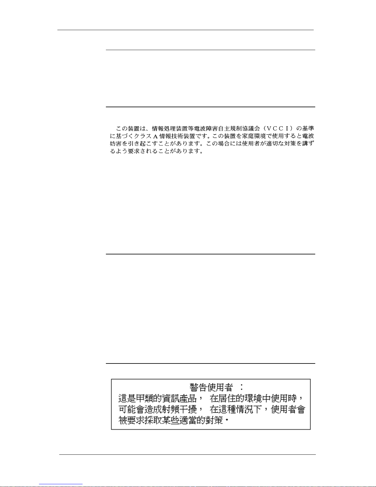
Tai wan
BSMI Class
A EMI
Statement

Appendix A: Safety and Regulatory Information
A-11
Australia
C-tick
Statement
WARNING
The system is designed to operate in a typical office environment.
Choose a site that is:
• Clean and free of airborne particles (other than normal
room dust)
• Well-ventilated and away from sources of heat including
direct sunlight
• Away from sources of vibration or physical shock
• Isolated from strong electromagnetic fields produced by
electrical devices
In regions that are susceptible to electrical storms, we
recommend you plug your system into a surge suppressor
and disconnect telecommunication lines to your modem
during an electrical storm.
• Provided with a properly grounded wall outlet
Do not attempt to modify or use the supplied AC power cord if it
is not the exact type required.
Ensure that the system is disconnected from its power source and
from all telecommunications links, networks, or modem lines
whenever the chassis cover is to be removed. Do not operate the
system with the cover removed.
Russia
Certification
The Packeteer 1200, 1550, 1700, 2500, 3500, 6500,
7500, and 10000 models are Russia GOST-R certified.

Appendix A: Safety and Regulatory Information
A-12
Proper Disposal of Packeteer Products
To reduce waste and to protect the environment from hazardous
materials, waste electrical equipment must be disposed of properly.
The crossed-out wheelie bin symbol pictured here and labeled on
Packeteer products (purchased after August 13, 2005) is a
reminder that electrical equipment should not be mixed in with
general trash or disposed of in a landfill. Once your Packeteer
product or component has reached its end-of-life, you should
dispose of it through a reputable, licensed hazardous materials
processor.
If you are located in one of the European Union Member States,
please refer to the product's end user license agreement for further
information regarding the proper disposal, reporting, and/or return
of the product to Packeteer.
For additional information and to obtain return instructions, please
go to the Packeteer website at http://www.packeteer.com/program/
recycling/.
RoHS Compliance
Packeteer supports the EU directive for Restriction of Hazardous
Substances (RoHS). PacketShaper models 1700, 3500, 7500, and
10000 Revision G are RoHS-compliant.
 Loading...