

Page 1

SX-8-EP
PoE-Powered Managed Gigabit Switch
with 8 Rear-Facing Ports
QUICK START GUIDE
Page 2

22
Page 3

33
Contents
Switch overview 4
Preparing to install the switch 5
Installation 5
Installing a rack bracket 6
Installating a wall mount 7
Logging in to the switch 8
Changing the IP address of the switch 9
Setting up Pakedge Zone & VLAN 10
Manually conguring VLANs 11
Console into the switch 13
Resetting IP address through the console 14
Factory defaulting through the console 14
Technical Support 16
Page 4

44
Switch overview
The SX Series switches are fully managed gigabit switches, designed to address a wide range
of networking needs. The SX Series switches are encased in high-end AV housings to appeal to
cutomers’ demand for aesthetics.
The following chart denes the features of the SX-8-EP:
Port speeds 10/100/1000 Mbps SFP Yes
Console port Yes SFP ports (dedicated) 1
Web GUI Yes Shared SFP No
Ethernet ports 8 PD port Port 1
Page 5

55
Preparing to install the switch
The SX-8-EP allows for multiple installation options. It is possible to mount it in an AV rack, mount
to a wall, or place on a desktop. When powering the SX-8-EP by PoE, installing is even easier since
proximity to an AC outlet is no longer a deciding factor to placement.
Tools required:
• Phillips screwdriver (if using rack-mount brackets)
• Computer with Ethernet interface and a modern web browser
• Optional: An integrated DB-9 port or USB-to-DB9 adapter may be necessary in order to use
the console interface.
• Ethernet cable
Installation
1 Remove the switch from the box.
2 Optional: If mounting the switch in a standard 19” AV rack, follow the instructions labeled
“Installing a rack bracket” on page 6. If wall-mounting the switch, follow the instructions
for “Installing a wall mount” on page 7. You may also use the included rubber feet to
place the switch on any desktop.
3 Connect power to the device.
4 Connect an Ethernet cable from your computer to any LAN port on the switch. You are now
ready to congure the switch with an IP address in your network range.
Page 6
66
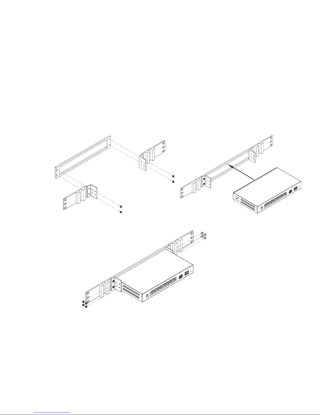
Installing a rack bracket
1 Secure the rack brackets to the faceplate bracket.
2 Slide the switch into the center opening of the faceplate bracket.
3 Secure the rack bracket/faceplate bracket assembly to the switch.
Page 7
77
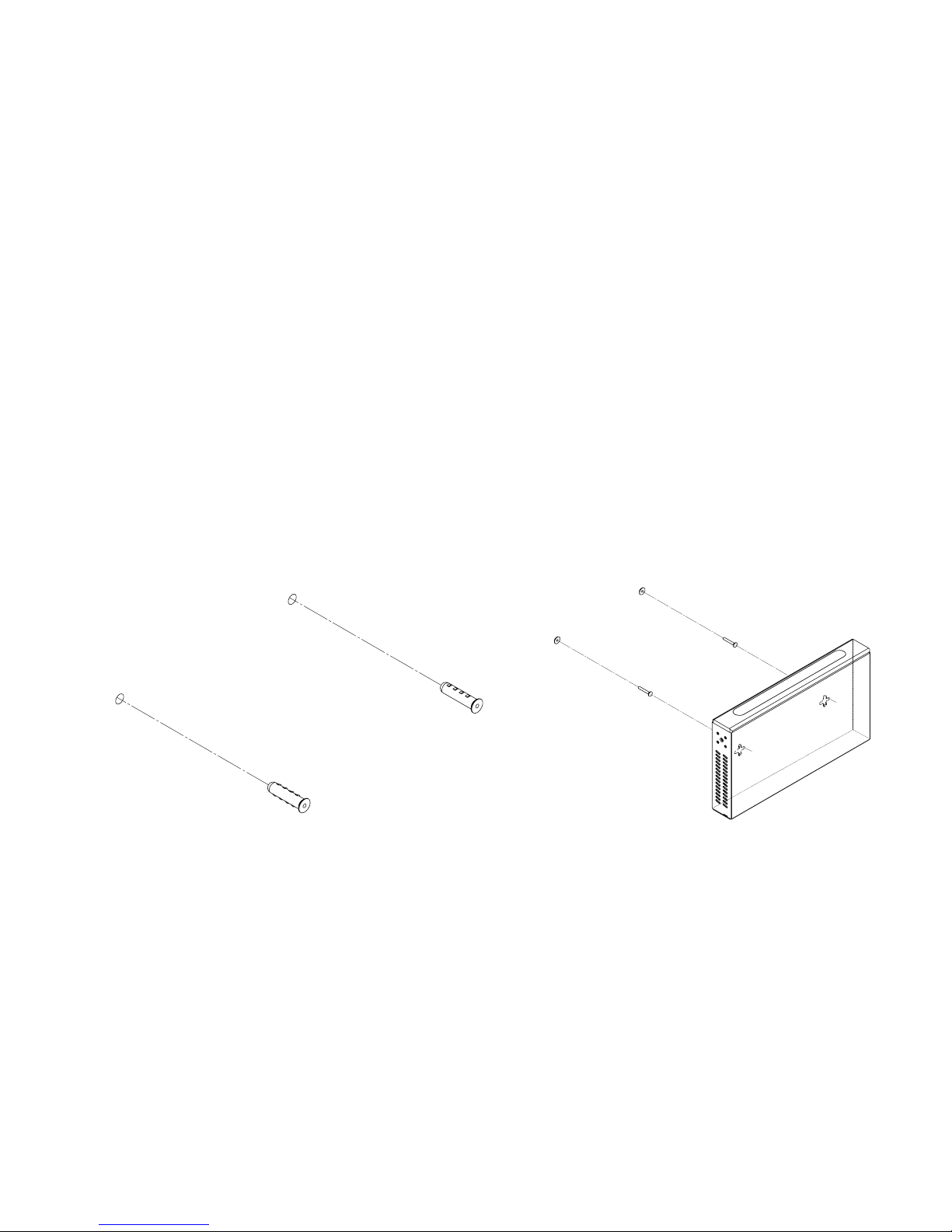
Installating a wall mount
1 Place the included template (rst and last page of this Quick Start Guide) at
the desired mounting location. Mark location of mounting points as noted on
template. The distance between the centerlines of the two mounting points
should be 5½ inches (140 mm).
2 Install the included drywall anchors at the marked locations. Screw the drywall
screws into the drywall anchors, leaving at least a 9/64 inch (3.5 mm) gap
between the top of the drywall screw head and wall.
3 Line the keyholes on the bottom of the switch with drywall screws, and mount the
switch onto the drywall screws.
Page 8
88
Logging in to the switch
1 Connect the SX switch to a power source. The PWR LED lights up and the fans start.
2 Connect a computer to any LAN port on the switch.
3 Congure the PC with a static IP address of 192.168.1.10 and subnet mask of
255.255.255.0 (Default Gateway and DNS can be left blank), and then open any browser.
4 In the browser, enter the switch’s default IP address of 192.168.1.205 into the address bar
and press Enter.
5 Enter the Username and Password. The default username is “pakedge” and the password is
“pakedges”.
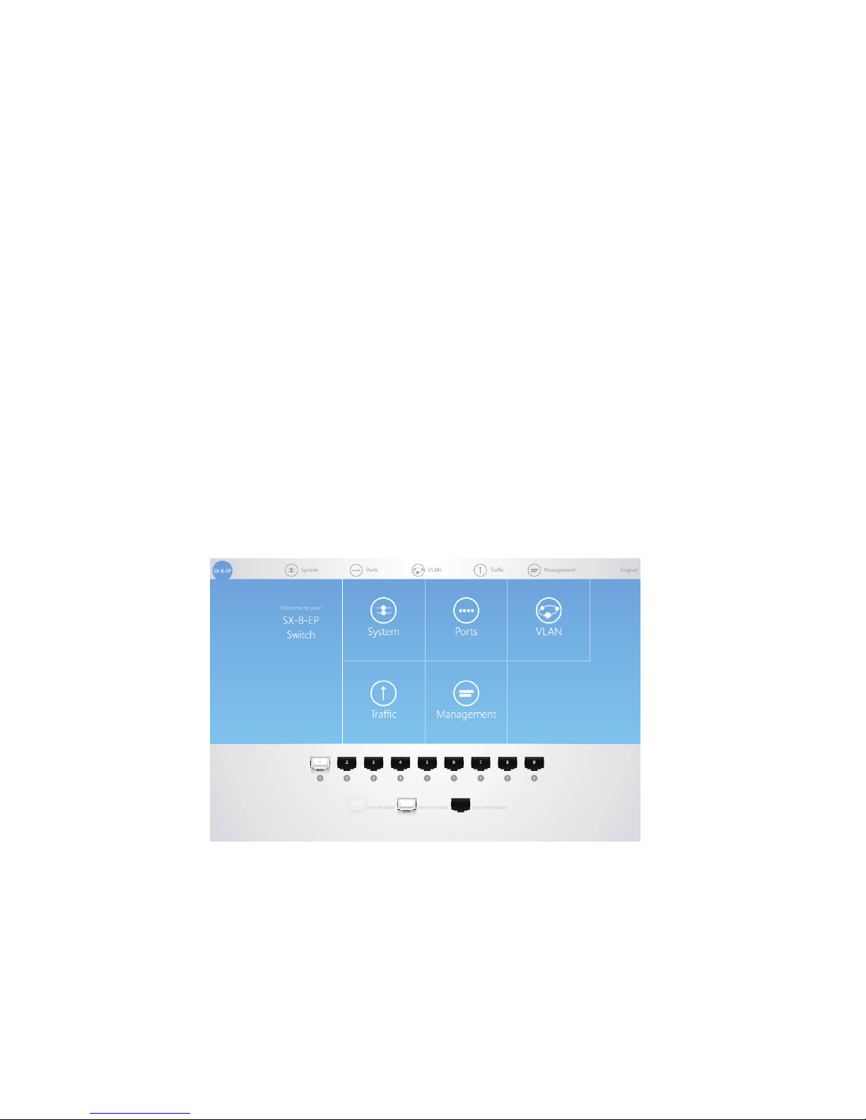
After you have logged in to the switch, you can access the GUI and make any changes you
want to. The following is an example of the switch dashboard.
Page 9

99
Changing the IP address of the switch
To congure the IP Address settings on the switch:
1 From the Dashboard, click System > System Settings > Basic Settings.
2 Enter the switch IP address in the box next to IP Address. By default, the switch IP address
is 192.168.1.205. You will also need to enter the Subnet Mask and Gateway settings for
your network. By default, on a Pakedge network the subnet mask is 255.255.255.0 and the
Gateway is 192.168.1.99.
3 Click Apply at the bottom of the page. The switch will be updated with the new IP settings.
If the IP address you have changed the switch to is in the same IP subnet range, you will be
redirected automatically. Otherwise, you will need to update your computer’s IP settings to
match the new IP address of the switch in order to access it again.
Page 10

1010
Setting up Pakedge Zone & VLAN
New to the SX Series switches are the Pakedge Zones. Pakedge Zones provide a simple way to
congure the switch to match the specialized VLAN settings of a Pakedge network.
This new VLAN conguration page allows for very quick implementation of VLAN settings across
all ports of the switch.
Page 11
1111
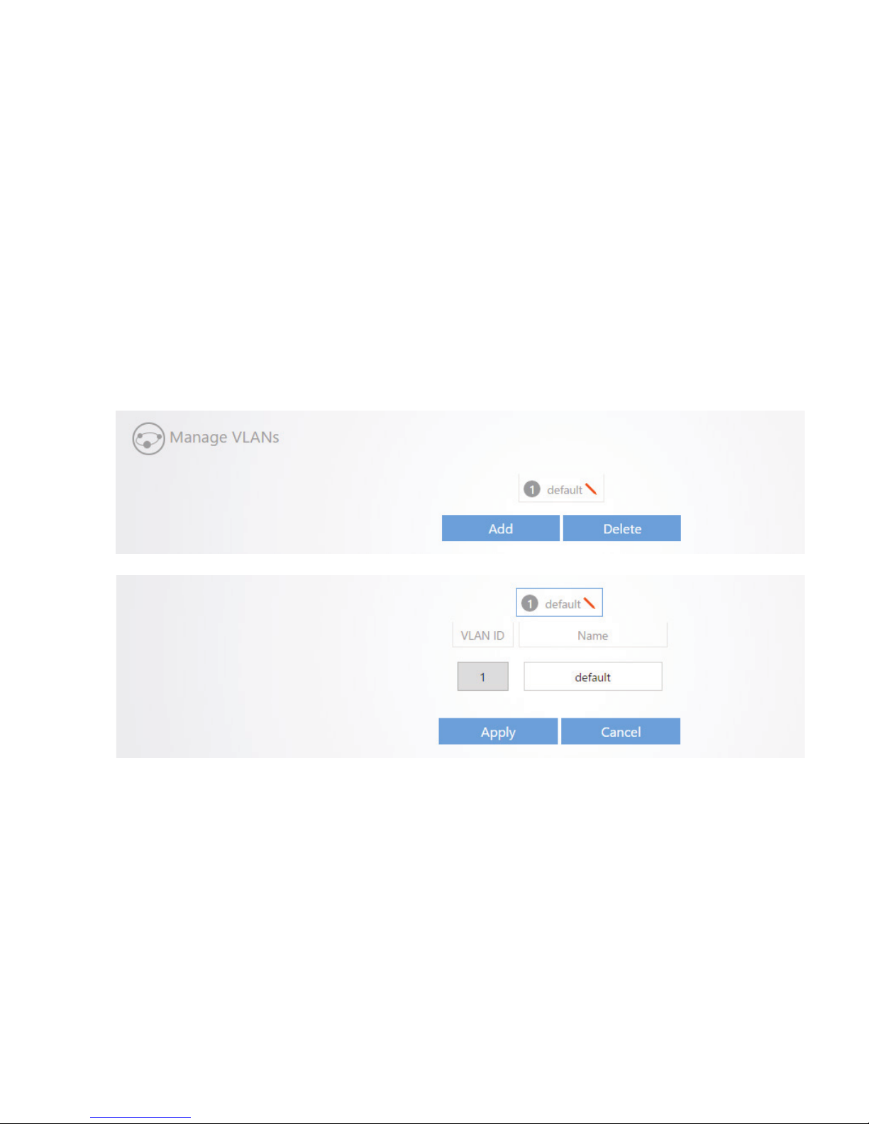
Manually conguring VLANs
1 To manually add and congure VLAN settings, go to VLAN > Conguration > Advanced.
2 Under the Manage VLANs section, click Add to input a new VLAN ID number and name,
then click Apply to save that VLAN to the switch. VLAN IDs 1-6 are color coded to match
the Pakedge Zones these are used for.
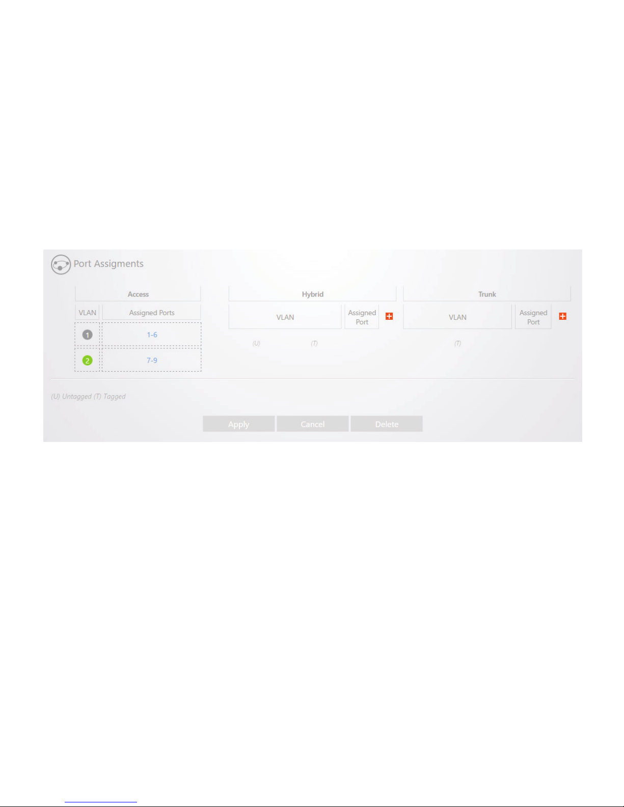
3 To congure ports as dierent VLANs, use the “Port Assignments” section.
Page 12
1212
4 To set ports with the ability to only access a single VLAN, click the VLAN you want to use
under Access, then click on the ports above you wish to set with that VLAN. After you have
the ports you want selected, click Apply at the bottom of the page to save those settings.
5 To set ports in Hybrid mode (one default VLAN and multiple tagged VLANs), click the “+”
symbol under Hybrid. You will then be in the Hybrid prole conguration mode.
6 Select the untagged default VLAN to be used on the port (normally VLAN1).
7 Select one or more other VLANs to be used for tagged VLAN trac.
8 Select the box under Assigned Port, then click on one of the ports above to set this prole
on a switch port.
9 Click Apply at the bottom of the page to save the settings.
Page 13

1313
Console into the switch
The SX Series switches have a console port to serve as a back-door entrance to the switch. This
can be benecial in case the switch is not functioning properly or if the incorrect IP address was
congured.
To console into the switch:
1 Connect the console cable to the console port on the back of the switch, then connect the
other end to your computer. If your computer doesn’t have a serial port, use a USB-to-serial
adapter.
On your computer, open PuTTY or Terra Term, enter the COM port that your computer is
using, then set the following:
Baud Rate: 115200
Character Size: 8
Parity Code: None
Stop Bits: 1
Flow Control: None
The following is an example if you are using PuTTY:
a. Click Session on the left side, select Serial for the connection type, then click Open
to initiate the console session.
b. After the connection is established, enter the switch username and password (default
is pakedge/pakedges). You now have console access into the switch.
Page 14

1414
Resetting IP address through the console
You can reset the switch’s IP address through the console. This can be helpful in case of
missconguration. You will rst need to console into the switch as previously described, then:
1 Type “show ip” and press Enter to see the current IP address.
2 Type “congure” and press Enter.
3 Type “interface vlan 1” and press Enter to edit the VLAN1 interface.
4 Type “ip address 192.168.1.205 mask 255.255.255.0” and press Enter.
5 Type “ip default-gateway 192.168.1.99” and press Enter (optional).
The switch should now be accessible on its default IP address.
Factory defaulting through the console
You can factory default the switch through console in case it is not functioning properly. You will
rst need to console into the switch as previously described, then:
1 Type “delete startup-cong” and press Enter.
2 Type “y” and press Enter.
3 Type “y” again to allow the switch to reboot.
The switch will now reboot and come back up at default settings.
Page 15

1515
Page 16

DOC-00225-C 2016-08-23 MS
Technical Support
For technical help:
www.pakedge.com/portal
(650) 385-8703
For non-technical inquires:
(650) 385-8701
For regulatory information:
www.pakedge.com/regulatory
11734 S. Election Road
Draper, UT 84020
www.pakedge.com
[email protected]
©2016 Pakedge Device & Software Inc. All rights reserved.
 Loading...