

Page 1
iDesign Disassembly Manual
Page 2
Required Tools
All disassembly procedures can be performed using the following tools:
Philips screwdriver
Disassembly Instructions
This document contains step-by-step disassembly instructions for the iDesign
(Epura) chassis. The instructions are clarified by images of the part that is being
removed or disassembled. Furthermore, the screws that are removed are shown
next to the image of the parts themselves.
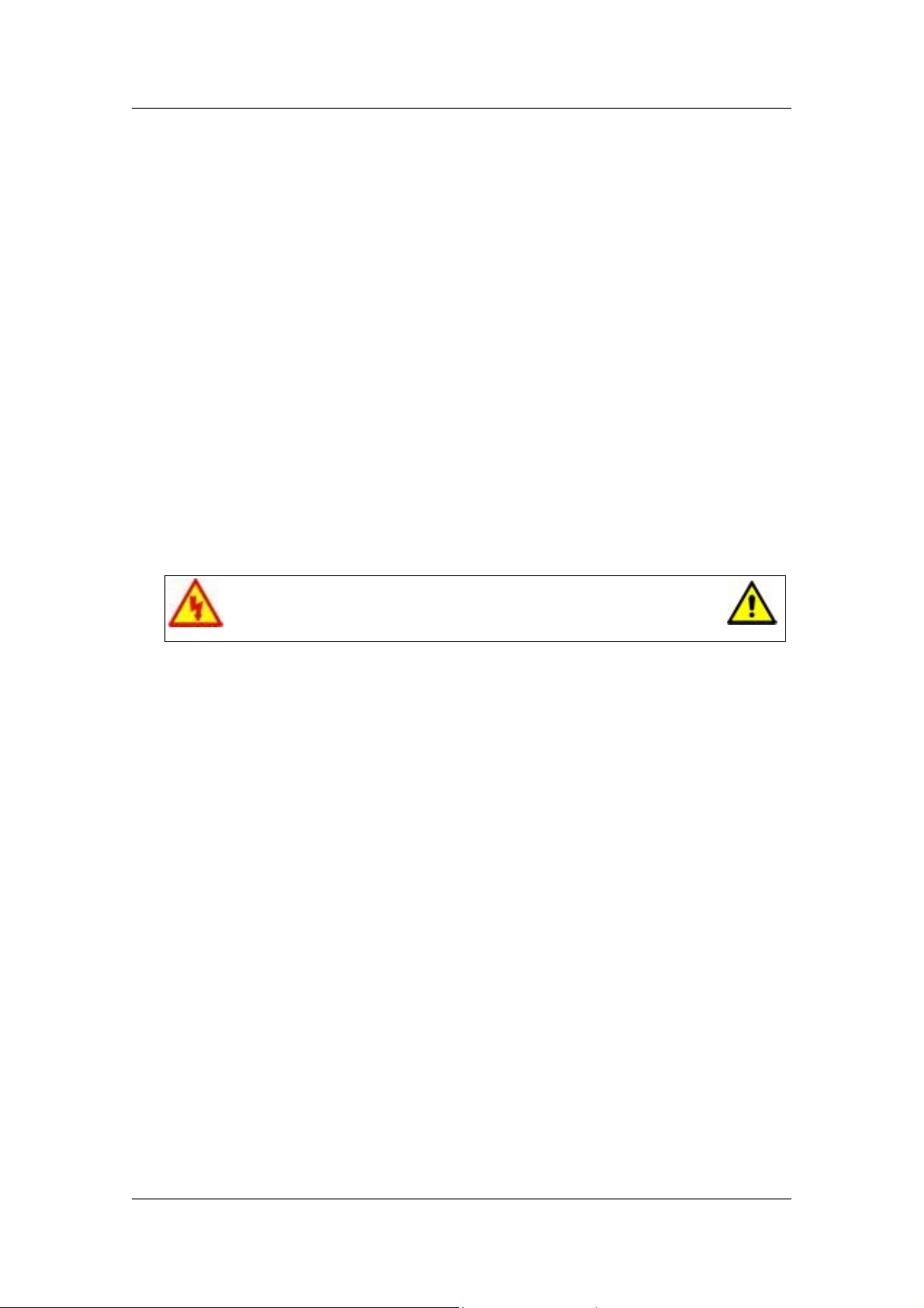
When disassembling the system unit, follow these general rules:
Do not disassemble the system into parts that are smaller than those specified
in the instructions.
Label all removed connectors. Note where the connector goes and in what
position it was installed.
Turn off the power and disconnect all power and all options.
Electrostatic discharge can damage computer components.
Discharge static electricity by touching a metal object before
removing the system unit cover.
Reassembly Instructions
Reassembly is the reverse of the disassembly process. Use care to ensure that all
cables and screws are returned to their proper positions.
iDesign Disassembly Manual - 2
Page 3
Opening the Chassis
Perform the following steps to open the chassis:
1. Disconnect all external data and power cables connected
to the computer.
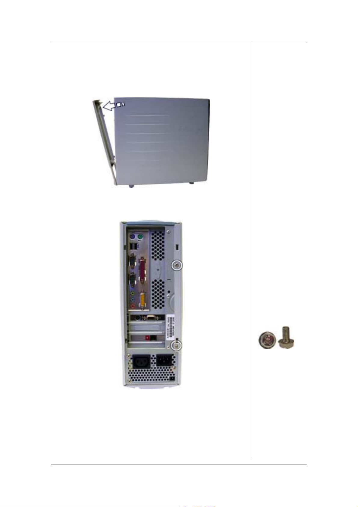
2. Gently pull the rear bezel diagonally from the chassis.
Fig. 1: Removing the rear bezel
3. Remove the screws that hold the side panel.
Fig. 2: Removing the side panel screws
4. Slide the side panel towards the back and pull it away from
the chassis.
iDesign Disassembly Manual - 3
Page 4
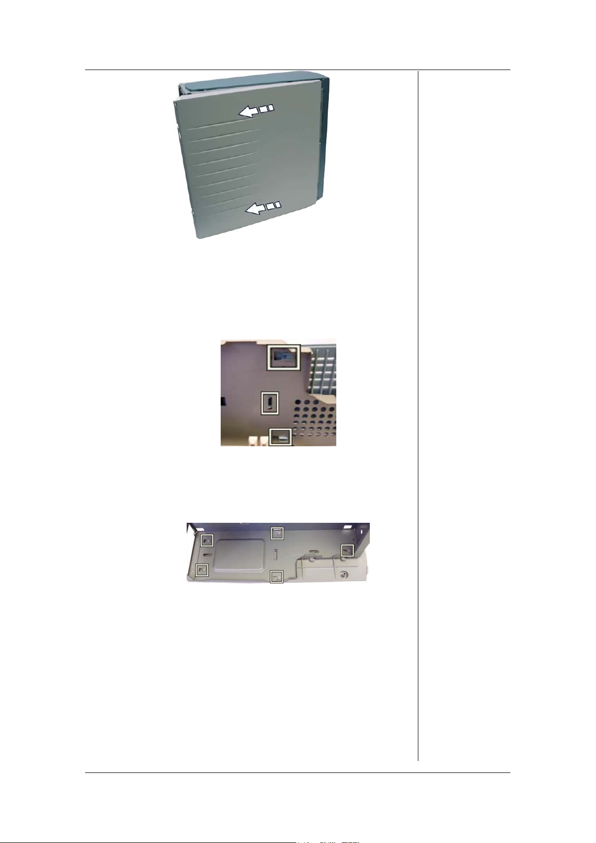
Fig. 3: Removing the side panel
5. If required, do the same with the other side panel.
6. If required, lay down the chassis on one side, carefully
slide the top bezel slightly backwards to unhook the
latches holding it in place, and lift the top bezel away from
the chassis.
Fig. 4: Removing the top bezel
7. If required, lay down the chassis on one side, carefully
slide the bottom bezel slightly backwards to unhook the
latches holding it in place, and remove the bottom bezel.
Fig. 5: Removing bottom bezel
Removing the Front Bezel
To remove the front bezel, open the chassis (see the section
Opening the Chassis) and continue as follows:
1. Gently unlock the three lateral latches that hold the front
bezel and pull it away to the opposite side.
iDesign Disassembly Manual - 4
Page 5

Fig. 6: Removing the front bezel
Removing the Drive Bracket
To remove the drive bracket containing the DVD/CD-ROM,
and the floppy disk drive, first open the chassis (see section
Opening the Chassis), remove the front bezel (see section
Removing the Front Bezel), and follow these steps:
1. Lay down the chassis on its side.
2. Disconnect all power and data cables from the drives
installed.
3. Remove the screws that hold the drive bracket to the
chassis.
Fig. 7: Removing the drive bracket
4. Slide the drive bracket out of the chassis.
Removing the DVD/CD-ROM Drive
To remove the DVD/CD-ROM drive, first open the chassis (see
section Opening the Chassis), remove the front bezel (see
section Removing the Front Bezel), remove the drive bracket
containing the DVD/CD-ROM and floppy disk drive (see the
section Removing the Drive Bracket), and follow these steps:
1. Remove the screws holding the DVD/CD-ROM drive.
2. Slide the DVD/CD-ROM drive out of the drive bracket.
iDesign Disassembly Manual - 5
Page 6

Fig. 8: Removing DVD/CD-ROM drive
Removing the Floppy Disk Drive
To remove the floppy disk drive, first open the chassis (see
section Opening the Chassis), remove the front bezel (see
section Removing the Front Bezel), remove the drive bracket
containing the DVD/CD-ROM and floppy disk drive (see the
section Removing the Drive Bracket), and follow these steps:
1. Remove the screws holding the floppy disk drive in the
drive bracket.
Fig. 9: Removing Floppy Disk Drive
2. Slide the floppy disk drive out of the drive bracket.
Removing the Hard Disk Drive
To remove the hard disk drive, first open the chassis (see
section Opening the Chassis), remove the front bezel (see
section Removing the Front Bezel), remove the drive bracket
(see section Removing the Drive Bracket), and follow these
steps:
1. Disconnect the power and data cable from the hard disk
drive.
2. Remove the screws in the front of the chassis holding the
hard disk drive bracket.
iDesign Disassembly Manual - 6
Page 7

Fig. 10: Removing the screws of the hard disk drive bracket
3. Slide the hard disk drive bracket out of the chassis.
4. Remove the screws that hold the hard disk drive in the
bracket and slide the hard disk drive out.
Fig. 11: Removing the hard disk drive screws
Removing Add-On Cards
To remove installed add-on cards, open the chassis (see
section Opening the Chassis), and follow these steps:
1. Disconnect all cables from the card to be removed.
2. Remove the screw holding the card in place.
Fig. 12: Removing the add-on cards
3. Carefully take out the card from the slot.
iDesign Disassembly Manual - 7
Page 8

Note
encounter an AGP slot with a special retention lock. Unlock the card
before taking it out from the AGP slot.
Depending on the motherboard (revision), you might
Fig. 13: AGP retention lock
Removing the SPDIF Assembly (If Present)
To remove the SPDIF card, open the chassis (see section Opening the
Chassis), then:
1. Disconnect the SPDIF assembly cable from the
motherboard.
Fig. 14: Disconnecting SPDIF assembly cable
2. Remove both screws holding the SPDIF assembly to the
back panel of the chassis and take out the SPDIF
assembly.
Fig. 15: Removing SPDIF assembly from chassis
Removing the Switch/USB Assembly
To remove the switch/USB assembly, open the chassis (see
section Opening the Chassis), remove the front bezel (see
section Removing the Front Bezel), remove the drive bracket
containing the DVD/CD-ROM and floppy disk drive (see the
iDesign Disassembly Manual - 8
Page 9

section Removing the Drive Bracket), then:
1. Disconnect the switch/USB assembly power cables from
the motherboard.
2. Remove both screws holding the switch/USB assembly to
the chassis.
Fig. 16: Removing the switch/USB assembly
3. Gently pull the cables through the orifice in the chassis.
Removing the Power Supply Unit
To remove the power supply unit, first open the chassis (see
section Opening the Chassis), then follow the steps below:
1. Lay the chassis down on one side.
2. Disconnect the power supply cables from all peripherals
and the motherboard.
3. Remove the screws at the back of the chassis.
Fig. 17: Removing the screws of the power supply unit
4. Carefully lift the power supply out of the chassis.
Removing the Motherboard
To remove the motherboard, open the chassis (see section
Opening the Chassis), remove the front bezel (see section
Removing the Front Bezel), remove the drive bracket
containing the DVD/CD-ROM and floppy disk drive (see the
section Removing the Drive Bracket), remove all add-on cards
iDesign Disassembly Manual - 9
Page 10

from their slots (see section Removing Add-On Cards),
remove the power supply unit (see Removing the Power
Supply Unit), then follow the steps below:
1. Disconnect all power and data cables connected to the
motherboard.
2. Remove any memory module installed (refer to the
motherboard documentation for instructions on how to
remove this component).
3. Remove the screws that hold the motherboard in place
and carefully take out the motherboard from the chassis.
Fig. 18: Removing the screws of the motherboard
Removing the System Fan (If Present)
To remove the system fan (if the system is equipped with one), open the
chassis (see section Opening the Chassis), remove the front
bezel (see section Removing the Front Bezel), remove the
drive bracket containing the DVD/CD-ROM and floppy disk
drive (see the section Removing the Drive Bracket), then
follow the steps below:
1. Disconnect the white system fan power connector on the
motherboard (the red/brown connector belongs to the CPU
fan).
Fig. 19: System fan connector
2. Pull the fan in the direction of the arrow on the image.
iDesign Disassembly Manual - 10
Page 11

Fig. 20: Removing the system fan
3. Unhook the system fan from the metal hooks on top of the
chassis and take it out of the system.
Fig. 21: Metal hooks on the chassis
Removing the Motherboard with Pentium 4
If the CPU installed is a Pentium 4, please perform these
additional steps before finally taking out the motherboard (see
section Removing the Motherboard):
1. Disconnect the power cable to the CPU cooler.
2. Remove the CPU cooler by unlocking the four latches.
Fig. 22: Removing the CPU fan
3. Remove the CPU cooler holder.
Fig. 23: Removing the CPU cooler holder
iDesign Disassembly Manual - 11
Page 12

4. Remove the CPU heatsink by removing the four screws.
Fig. 24: Removing the CPU heatsink
5. Remove the CPU heatsink bracket screws.
Fig. 25: Removing the CPU heatsink bracket
iDesign Disassembly Manual - 12
Page 13

iDesign Disassembly Manual - 13
 Loading...