


Model Two
®
HDCD
A/D Converter
D/A Converter
Digital Processor
User’s Manual
Ver sion 3.01
PN 9300-0020 Rev. C
®
Euphonix, Inc.
220 Portage Avenue, Palo Alto, CA 94306
Phone (650) 855-0400 Fax (650) 855-0410

Overview
Model Two HDCD® User’s Manual
2
This User’s Manual contains information needed to properly install an d operate the Mod el
Two. Please read the Installation section before connecting AC power! The In stallation
and Set Up & Operation secti on s o f this m anu al sh ould also be r ead befor e first use o f the
Model Two.
Model Two User’s Manual Versions correspond to Model Two Software Versions. Verify that
the Software Version listed on page one of this manual matches the Version listed in the
Software V ersion Men u accessible through th e Model T wo’s Graphic Display. For details, see
page 65 in the Reference Section. If the Versions do not match, please contact Euphonix
to obtain the correct User’s Manual, or update the Software Version.
Euphonix is committed to the ongoing support of our products and customers. If we can be of
assistance in any way, please call us at (650) 855-0400, Monday through Friday, between 9:00 AM
and 5:00 PM Pacific Time, or fax us at (650) 855-0410. You can also contact customer service by
visiting our Web site at www.euphonix.com. For additional information on HDCD products and technology, please visit www.hdcd.com.
©2002 Euphonix, Inc.
All rights reserved.
Rev. C - January 2002
PACIFIC MICROSONICS
INC.
®

Table of Contents
Model Two HDCD® User’s Manual
3
Installation
Model T wo Processor, 4
Model Two Power Supply, 4
DC Power Cable, 4
AC Power Cable, 4
Power Up, 5
Setting Analog Connector Pin Polarity, 5
Setting Analog Input Attenuation, 6
Analog Connections, 7
Analog Output Networks, 7
Digital Connections, 7
AES Signal Ground Isolators, 8
Model Two Processor Description, 9
Model Two Processor Front Panel Controls, 9
Model Two Processor Rear Panel, 10
Model Two Power Supply Description, 11
Setup & Operation
Model Two Rev. 3.01 Software Features, 12
Front Panel Controls and Displays, 13
Signal Level Meter, 13
Meter Source, 14
Meter Display Mode, 14
Peak Level Hold, 14
Signal Over Segments, 15
Peak Extension/HDCD Limiting Meters, 15
Meter Reset Button, 15
Meter Setup, 15
Monitoring, 16
Power Switch, 16
Graphic Display, 17
Menu Up and down Buttons, 17
Function Buttons, 17
Enter Button, 17
Rotary Control, 17
System Status Indicator, 18
Clock Indicators, 18
HDCD Indicator, 18
Operating Modes, 19-23
Presets, 24
Factory Preset Configurations, 24-25
Using the Model Two as a Master Word Clock Generator, 26
Setup for AD and DD Operating Modes, 26
Setup for AD and DD Multichannel Operation, 26-27
Recording From an Analog Source, 27
Setup for 44.1/48 kHz, 88.2/96 kHz
and 176.4/192 kHz A/D Conversion, 27-29
Setup for 44.1/48kHz A/D conversion
With Simultaneous D to D Processing, 29
Digital Post Production Processing, 30
Setup for 44.1 kHz Word Length Conversion
& HDCD 16-bit Encoding, 30
Setup for 88.2/96 kHz to 44.1/48 kHz Decimation
& Word Length Conversion, 30
Setup for 44.1/48 kHz to 88.2/96 kHz
Interpolation & Word Length Conversion, 31
Setup for 176.4/192 kHz to 44.1/48 kHz
Decimation & Word Length Conversion, 32
Setup for 44.1/48 kHz to 176.4/192 kHz
Interpolation & Word Length Conversion, 32
DAC-Monitoring System Performance Optimization, 32-33
Compact Disc Release Mastering, 33
HDCD Silence, 33
Processing HDCD 16-bit Signals, 33
A/D Conversion of Analog Tape Recordings, 34
Creating the 16-Bit HDCD Release Sound You Want, 35
HDCD16-bit Amplitude Encoding & Dither Options, 35
Peak Extension & HDCD Limiting, 35
DSP Gain, 36
Low Level Extension, 36
Operating Techniques, 37
HDCD 16-bit Dithers, 37
Limited Dynamic Range Pop or Rock, 37
Wide Dynamic Range Jazz or classical, 38
Reference
Menu Structure, 39
Menu T ree, 40
Menu Descriptions, 41
Operating Menu, 41
Second Operating Menu, 41
Monitor Source Menu, 42
Levels Menu, 42-44
Setup Menu, 44-45
44.1/48 Base Sample Rate Menu, 45
Operating Mode 1_X Modes Menu, 46
Operating Mode 2_X Modes Menu, 46
Operating Mode 4_X Modes Menu, 47
Digital Output Menu, 47-48
Digital Output 1 Word Length Menu, 48
Output 1 HDCD_16 Dither Menu, 48-49
Digital Output 2 Word Length Menu, 49
Output 2 HDCD_16 Dither Menu, 50
Digital Output Word Length Menu, 50
Digital Output Phase Invert Menu, 51
Digital Output HDCD Setup Menu, 51
Digital Output Format Menu, 52
Analog Input Menu, 52
A/D Reference Clock Menu, 53
A/D Filter Mode Menu, 53
Monitor Input HDCD Code Detect Menu, 54
Monitor Reference Clock Menu, 54
External Ref Clock Frequency Menu, 55
Monitor Digital Input Format Menu, 55
Digital Input Menu, 56
Digital Input HDCD Code Detect Menu, 56
Digital Input HDCD_16 Decoding Menu, 57
2X To 1X Filter Mode Menu, 57
Digital In Reference Clock Menu, 58
Digital Input Format Menu, 58
Recall Presets Menu, 59
System Menu, 59
Front Panel Display Menu, 60
Analog Polarity Menu, 60
DAC-System Optimize Men u, 60
Monitor Setup Menu, 61
Meter Setup Menu, 61
Meter Overload Light #1 M enu, 62
Meter Overload Light #2 M enu, 62
Store Presets Menu, 63
Store Preset Menu, 63
Rename Preset Menu, 64
Test Functions Menu, 64
Software Version Menu, 65
System Software Download, 65
Background, 65
Required Equipment, 65
Download Procedure, 66-67
Self-Test, 67
HDCD Overview, 68
16-bit Encoding, 68
16-bit Decoding, 68
HDCD Indicator, 69
Peak Extension and HDCD Limiting, 69
Low Level Extension, 70
Gain Scaling, 70
Processing HDCD 16-Bit Signals, 70
HDCD Silence, 70
Technical Specifications, 71-72
Appendix, 73-74
Rev. C - January 2002
PACIFIC MICROSONICS
INC.
®

Installation
Model Two HDCD® User’s Manual
4
Initial Configuration
PLEASE: Read the following installation instructions BEFORE connecting AC power!
Model Two Processor
The Processor should be placed in an area free from noise generating devices such as
power supplies and power amplifi ers . A t least six in ch es sh ould be pr ovi ded to the rear o f
the unit to allow for heat dissipation and airflow. A vibration isolated fan stabilizes the
Processor’s thermal environment. The Processor is designed for rack mounting, with four
front panel mounting holes and two rear rack mounting brackets, which must be used
unless the Processor is supported by a shelf. The rear brackets are included, but are not
installed on the unit when shipped.
A description o f the Processor is on pag e 9 and its I/O conn ection s are shown on pag e 10.
Model Two Power Supply
The Power Supply sh ould not sit dir ectly on top o f or un d ern eath th e Processor. Note that
the Power Supply does not have a power switch an d is active only when conn ected to th e
Processor unit via the DC power cable and the Processor power is turned on.
A description and illustration of the Power Supply is on page 11.
DC Power Cable
CAUTION: Do not connect or disconnect the DC power cable from the Processor or
Power Supply while the Power Supply AC power cable is plugged in. Always unplug
the AC power cable before connecting or disconnecting the DC power cable.
The receptacle (fem ale) end o f th e DC power cable is conn ected to th e DC P ower Input on
the back of the Processor, and the plug (male) end is connected to the DC Output on the
Power Supply. The connectors are keyed to en sure correct alignmen t an d have a silver d ot
at the “up” or 12 o’clock position.
AC Power Cable
CAUTION: Set the Power Supply AC Line Voltage before connecting the AC power
cable! Line Voltage settings are 100V, 120V, 220V, and 240V, 50/60 Hz, + 5% to - 10%.
Total power consumption is 200 Watts. If you are unsure of the actual line voltage,
measure it before connecting!
When connectin g to 120 volt AC power, use a grounded three pr ong IEC plug an d cord set.
When connectin g to 100, 220, or 240 volt AC power, use a proper grounded plug an d cor d
set for that application.
Rev. C - January 2002
PACIFIC MICROSONICS
INC.
®

Installation
Model Two HDCD® User’s Manual
5
AC power for th e Model T wo should be supplied by th e same circuit and pr eferably the same
power outlet group as the AC power source for other equipment, such as analog tape
machines or consoles , wh ose outputs will be conn ected to the M od el T wo’s an alog inputs .
This will minimize the possibility of ground loops.
Power Up
Press the Power Switch on the Processor front panel to turn on the Processor and Power
Supply. The System Status Indicator will be lit orange, the A/D and D/A Clock Indicators
will be lit green, and the HDCD Indicator will be lit purple. The Graphic Display will momentarily display th e following messag es: “HDCD BOOT VERSI ON”, “ST ARTING HDCD...” and
“Loading DSP#1..” through “#8”. The System and Clock Indicators will then usually indicate normal oper ation (green) an d the HDCD Indi cator will go dark or r emain lit depen ding
on system set up. Power up is complete when an Operating Menu appears on the Graphic
Display similar to the one shown below.
At power up all settings will remain as they were prior to power off. From the Operating
Menu, all Processor functions are accessible. Function buttons (see page 17) are used to
navigate thr ough menus an d select items within th e men us. Selected items becom e active
by pressing th e ENTER button, or by toggling between selecti ons. A t any time , the Oper ating Menu can be accessed by pressing and holding the MENU UP button.
Setting Analog Connector Pin Polarity
The Processor allows th e XLR connector pin polarity o f the an alog input and outputs to be
set to either pin 2 or 3 hot. Th e factory default settin g is pin 2 hot. T o verify or change the
polarity setting, go to th e Analog Polarity Menu. Fr om th e Operatin g Men u select (SETUP/
MORE.../SYSTEM/POLARTY). To chang e, use the functi on button s to select eith er PIN2HOT
or PIN3HO T , and press ENTER to activate . For additi onal inform ation, see the An alog Polarity Menu on page 60.
Rev. C - January 2002
PACIFIC MICROSONICS
®
INC.

Installation
Model Two HDCD® User’s Manual
6
Setting Analog Input Attenuation
Analog input attenuation is set in 1 dB steps allowing a peak input signal level over the
rang e of +24 dBu to +12 dBu to produ ce full scale digital recor d level. The Mod el Two is set
at the factory to +18 dBu, whi ch is a typi cal peak signal level (With an operatin g level of
+4 dBu, and headroom of 14 dB, the peak level will be +18 dBu.). Analog input level
attenuati on is set by placing jumpers on pins located behind a cover panel on th e Processor’s
rear panel, dir ectly above the XLR an alog input connectors. T o access th e jumpers, r emove
the two thumb screws holding the panel in place. The pins and jumpers are located as
follows:
+12 +12+18 +18+23 +23
Jumpers set for +12 dB
The twelve pairs of pin s on the left set Chann el 1 and th e twelve pairs of pin s on the ri ght
set Channel 2. Placing the jumpers on the outermost pair of pins on each side provides
maximum input sensitivity; a +12 dBu input signal will generate full scale record level.
Each position inwar d of the jumpers pr odu ces 1 dB of atten uati on. Placing th e jumpers on
the innermost pair of pins on each side produces 11 dB of attenuation, which will then
require a +23 dBu input signal for full scale record level.
+12 +12+18 +18+23 +23
Jumpers set for +23 dB
If no jumpers are in stalled, 12 dB of attenu ation is produ ced, requirin g a +24 dBu input for
full scale record level. The unused jumpers should be stor ed horizontally across two pins,
as shown below, to keep them secure.
+12 +12+18 +18+23 +23
Rev. C - January 2002
PACIFIC MICROSONICS
No Jumpers set for +24 dB
INC.
®

Installation
Model Two HDCD® User’s Manual
7
Analog Connections
Analog Input and Output connections on the Model Two are balanced, using 3-pin XLR
connectors with either pin 2 or 3 set as hot (software selectable) and pin 1 as ground.
Input impedance is ≥ 13 kΩ balanced (≥ 6.5 kΩ per leg); output impedance is 20 Ω
balanced (10 Ω per leg). If the audio source driving the Model Two is single ended, a
balanced interconnect cable should be used with the return wire tied to ground at the
sending en d. If th e au dio output fr om th e Mod el Two must d rive an unbalanced load , use
pin 2 as high, pin 1 as ground, and lift pin 3 at the load or use pin 3 as high, pin 1 as
ground, and lift pin 2 at the load. CAUTION: Never connect the unused low pin to
ground, (pin 1) as that will short circuit one side of the Model Two’s actively balanced, DC coupled, output amplifier, and seriously degrade performance.
Analog audi o conn ecti on s an d grounds should be isolated electri cally an d physically from
digital signals, power conduits, and other noise sources. Audio cables should have low
impedance grounds and one-hundred percent RF shielding. Cables using a foil shield and
drain wire construction should not be used. Th ey can produce voltages in the signal path
due to ground currents flowing between different pieces of equipment.
Analog Output Networks
HDCD Processor Analog Output Networks (AON’s) are designed to improve the high frequency impedan ce match between the Mod el Two’s D/A analog output imped ance , which is
about 10 Ω per leg, and the characteristic impedance of typical analog audio cables,
which is about 60 Ω. The improved impedance match better terminates reflected high
frequency energy in the cable, which can improve sonic clarity and purity. The AON’s are
design ed to be connected between the Model Two’s analog outputs, and the au dio cables
used to feed the monitoring system. Two AON’s are provided with each Model Two.
Use of the AON’s is optional. Depending on system variables, including the power bandwidth and type of monitor power amplifiers used, and the length of audio cables, the
sound quality of the Model Two’s D/A’s may be preferred with or without the AON’s. It is
best to experimen t by listening to a wide vari ety of different types o f source material, both
with and without the AON’s installed. Note: The AON’s should be used only with load
impedances that are greater than 4 kΩ balanced (2 kΩ per leg). The AON’s are designed
only for use with the Model Two. Use with other products is not recommended and may
result in unsatisfactory performance.
Digital Connections
The Digital Inputs an d Outputs use 3-pin XLR connectors with pins 2 an d 3 active , and pin
1 connected to chassis ground. Input and output impedances are 110 Ω balanced. The
signal format is AES3.
Rev. C - January 2002
PACIFIC MICROSONICS
INC.
®

Installation
Model Two HDCD® User’s Manual
8
For best performan ce, AES3 cables should have th e chassis ground path isolated by a series
100 Ω resistor. Use of a low capacitance isolation transformer at the Model Two’s AES
signal inputs, or the AES Signal Ground Isolator described below at both inputs and outputs is also recommen ded . Cables sending AES3 or syn chronizati on sign als from th e Mod el
Two to other equipment should have transformer isolation placed at the inputs of the
receiving equipm ent. If external tr ansformers ar e used they should always be at th e receiving end of the digital signal path and never at the transmitting end.
The W ord Clock Ref Input/Output uses a BNC conn ector with its shield isolated fr om chassis ground . An e xternal 75 Ω termin atin g r esistor m ust be used when Word Clock Ref is in
input mode. This allows a high impedance loop-through connection. When configured as
an output by selecting Referen ce Clock Master M od e (SETUP/INPUT/REFCLK/MASTER), th e
Word Clock Ref conn ector outputs a special AC coupled wor d clock. See pages 26 and 27 for
more inf ormati on. BNC wor d clock cables should not use low capacitance isolati on tr ansformers because they are unable to pass TTL level signals.
AES Signal Ground Isolators
Pacifi c Mi cr osoni cs AES Si gn al Gr oun d Isolators are desi gn ed to br eak gr ound loops which
can occur between the grounds of digital and analog signal cables when they are connected together by a single device that has both digital and analog signal connections,
such as the Mod el T wo HDCD Processor. If not properly isolated, noise curr ents on gr ounds
have the potential to seriously degrade A to D and D to A converter performance.
The AES Signal Ground Isolators should be connected to all AES digital signal inputs and
outputs at the Model Two whenever they are in use. The AES Isolators are designed to be
used in series with standard AES cables that are connected to digital recorders, editing
workstations, etc. Four Isolators are provided with each Model Two.
The AES Groun d Isolators consist of a n umber of turns of pr ecision 110 Ω balanced , shielded
cable fed through multiple ferrite cor es, each having a differen t selected permeability . The
cable is terminated with XLR-3 connectors . This construction pr ovides 160 µ H of indu ctive
filtering effective over a very wid e rang e of fr equencies . A 100 Ω resistor is also placed in
series with the pin 1 ground connection, providing further isolation.
Note: P acific Mi crosonics r ecomm ends that as g eneral pr acti ce , a 100 Ω resistor should be
installed in series with the pin 1 (shield) connection at the female connector end of all
AES cables to reduce the potential of digital ground loop noise.
Rev. C - January 2002
PACIFIC MICROSONICS
INC.
®

Installation
Model Two HDCD® User’s Manual
9
Model Two Processor Description
The Processor is contained in a 3 R.U. (5.25”) high, 19” wide X 19.25” deep, rack mount
enclosure with adjustable r ear rack ears. The Pr ocessor contains th e following subsystems:
Analog to Digital Converter (ADC), Digital Signal Input/Output (DIO), Digital Signal Processor (DSP), Digital to Analog Converter (D AC), and Fr ont Pan el Controller (FPC). Th e ADC
converts 2 channels of analog signals to digital at a sampling frequency of 192 kHz or
176.4 kHz. The DIO r eceives an d tran smits AES3 d ata, wor d clock, an d RS-232 serial d ata.
The DSP performs all HDCD encoding, decoding, frequency and word length conversion,
digital signal gain changes, etc., employing eight Motorola 56009 Digital Signal Processors and one P acifi c Microsoni cs PMD-100 HDCD Process Decod er ASIC. Th e DAC converts 2
channels of 24-bit to 16-bit di gital d ata to an alog si gn als . Th e FPC pr ovides the in terf ace
between the DSP and the front panel graphic display, signal level meters, and controls.
All Processor contr ols, e x cept the An alog Input A ttenu ator, are located on the front pan el
as shown below:
P A C I F I C
M I C R O S O N I C S
POWER
1
6
SYSTEM
7
CLOCK
A/D D/A
UP DOWN
MENU
2
8
9
10
3
11
METER
RESET
ENTER
4
1 “POWER” Switch 7 “CLOCK” Indicators
2 “MENU” “UP” and “DOWN” Buttons 8 “HDCD”Indicator
3 Function Buttons 1-5 (left to right) 9 Signal Level M eters
4 “ENTER” Button 10 Peak Extension Meters
5 Rotary Control 11 “METER RESET” Button
6 “SYSTEM” Status Indicator 12 Graphic Display
12
5
Rev. C - January 2002
PACIFIC MICROSONICS
INC.
®

Installation
Model Two HDCD® User’s Manual
Processor rear panel I/O connections and Analog Input Attenuator.
10
4a
PUSH
AES In
1
4b
PUSH
Analog Input
5
2
RS-232
AES In
2
+12 +12+18 +18+23+23
PUSH PUSH
1
65
7
PUSH
AES Out
1
2
AES Out
2
10
AES In
Ref
9
8
Word
Clock
Ref
1
Analog Output
5
3
1
2
1 DC Power Input Connects to the DC Output on the Power Supply using
(28-pin male) the supplied DC power cable.
2 Analog Input Left and right inputs accepting +12 to +24 dBu peak
(XLR balanced female) level analog signals. Pin polarity is selectable.
3 Analog Output Left and right outputs producing up to +24 dBu peak
(XLR balanced male) level analog signals. Pin polarity is selectable.
4a AES In 1 Two or one channel AES3 format digital signal
(XLR balanced female) input.
4b AES In 2 Two or one channel AES3 format digital signal
(XLR balanced female) input active only in certain modes.
5 RS-232 Serial data port for external computer loading
(D-Sub 9-Pin male) of system software.
6 AES Out 1 Two or one channel AES3 format digital signal
(XLR balanced male) output.
7 AES Out 2 Two or one channel AES3 format digital signal
(XLR balanced male) output.
8 AES In Ref AES3 format digital signal input used for external
(XLR balanced female) A/D clock sync reference.
9 Word Clock Ref I/O Square wave, AC coupled, digital signal input/output
(BNC) Unterminated used for word clock sync reference. Use as an input
requires external 75 Ω termination.
10 Analog Input Access panel for jumper selectable analog input
Attenuator attenuator.
Rev. C - January 2002
PACIFIC MICROSONICS
INC.
®

Installation
Model Two HDCD® User’s Manual
11
Model Two Power Supply Description
The Power Supply is contained in a 14” wide X 2.5” high X 12.25” long enclosure and
connects to the Pr ocessor using a 6 foot multi conductor DC power cable . T o prevent groun d
loops from occurring between the AC power ground and audio signal ground, there is no
ground connection between the Power Supply and the Processor. The Power Supply connects to a 100V to 240V, 50/60 Hz AC power source using a standard IEC grounded AC
power cord. The rear panel connections on the Power Supply are as shown below:
AC Line Voltage
Select
1 DC Output Connector Connects from the Power Supply to the DC Input on the
(28-pin female) Processor using the supplied DC power cable.
2 AC Line V oltag e Select Lin e voltag e selecti on: 100V, 120V , 220V, 240V, AC, 50/60
Hz. (USA units are preset to 120V) AC input voltage must
be within a + 5% to - 10% range of the selected voltage.
3 AC Power Fuse Requires 3A (100V-120V) or 1.5A (220V-240V) 3AG fast
blow fuse.
4 AC Input Connector Connects to AC power outlet using grounded IEC AC
(IEC 3-pin male) power cord.
Rev. C - January 2002
PACIFIC MICROSONICS
INC.
®

Setup & Operation
Model Two HDCD® User’s Manual
12
Model Two Rev. 3.01 Software Features
1. Precision M aster W ord Clock Output capability in all AD an d DD oper atin g mod es . This
feature greatly reduces audible D/A conversion distortion caused by digital input signal
time base jitter by allowing both the A/D and D/A converters to be clocked by th e Model
Two’s pr ecision in ternal clock. Th e M od el T wo can also gen er ate or lock to either 1X or 2X
reference clock frequencies in both AD and DD modes. See pages 26-27 for details.
2. Dual clock family operation at multiples of 44.1 kHz or 48 kHz, allowing A/D conversion, D/A conversion and digital processing at 192 kHz, 176.4 kHz, 96 kHz, 88.2 kHz,
48 kHz, and 44.1 kHz. Digital I/O is selectable between sin gle wire, double speed, or d u al
wire , single speed AES at 88.2 kHz and 96 kHz. Input and output settin gs are ind ependent.
3. HDCD for DVD-Audio, including automatic 24-bit, 20-bit, and 16-bit HDCD LSB code
insertion at all sampling frequencies to allow HDCD process detection by HDCD equipped
DVD-Audio playback equipment.
4. 44.1/48 kHz to 88.2/96 kHz and 176.4/192 kHz high resolution HDCD interpolation
filtering to provide very high accuracy for both D/A conversion and high sample rate
processing of 44.1/48 kHz signals.
5. HDCD Limiting, which is identical in function to Peak Extension, except that the
limiting curve is not undone during HDCD decoded playback.
6. DAC-System Optimize, which allows the operation of the Model Two’s D/A converters
to be precisely optimized to the performance characteristics of the monitor electronics
and power amplifier being used.
The Model Two has several new Operating Modes and Setup Menus to provide these capabilities. Descriptions of the Operating Modes and Menus are at the following locations:
Setup and Operation Reference
Operating Modes, pgs. 19-23 Menu Tree, pg. 40
Factory Preset Configurations, pgs. 24-25 Second Operating Menu, pg. 41
Using the Model Two as a Master System 44.1/48 Base Sample Rate Menu pg. 45
Word Clock Generator, pgs. 26-27 Operating Mode Menus, pg. 46
Recording From an Analog Source pgs. 27-30 Digital Output Format Menu, pg. 52
Digital Post Production Processing, pgs. 30-32 Analog Input Menus, pgs. 52-56
DAC-System Optimize, pg. 32 Digital Input Menus, pgs. 56-59
HDCD Limiting, pg. 35 DAC-System Optimize Menu, pg. 60
HDCD 16-bit Dithers, pg. 37
Rev. C - January 2002
PACIFIC MICROSONICS
INC.
®

Setup & Operation
Model Two HDCD® User’s Manual
13
Front Panel Controls and Displays
All Processor contr ols, e x cept the An alog Input A ttenu ator, are located on the front pan el
shown below:
P A C I F I C
M I C R O S O N I C S
POWER
1
6
SYSTEM
7
CLOCK
A/D D/A
UP DOWN
MENU
2
8
9
10
3
11
METER
RESET
ENTER
4
1 “POWER” Switch 7 “CLOCK” Indicators
2 “MENU” “UP” and “DOWN” Buttons 8 “HDCD”Indicator
3 Function Buttons 1-5 (left to right) 9 Signal Level Meters
4 “ENTER” Button 10 Peak Extension Meters
5 Rotary Control 11 “METER RESET” Button
6 “SYSTEM” Status Indicator 12 Graphic Display
12
5
Processor control and display functions are described below.
Note: Menu selections, startin g fr om th e Oper atin g M en u, to access a menu or feature ar e
shown in (parentheses).
Signal Level Meters
The Signal Level Meters consist of two, four color LED bar graphs which indicate program
level for each channel. The LED ranges by color are shown below:
Green = - ∞ to -11 dB
Yellow = -10 to -1 dB
Amber = 0 dB
Red = OVER
The ran ge of -60 to -40dB is indicated in 5 dB steps, -40 to -20dB in 2 dB steps, and -20
to 0dB in 1 dB steps. OVER indication has two dedicated segments with individually ad-
Rev. C - January 2002
PACIFIC MICROSONICS
®
INC.

Setup & Operation
Model Two HDCD® User’s Manual
14
justable parameters (see pag es 59 and 60 in th e Refer ence Section to set OVER indicati on
parameters). Meter brightness is set in the Front Panel Display Menu (SETUP/MORE.../
SYSTEM/PANEL).
Meter Source
Meter signal sources are selected in the Operating Menu. The source options are: OUT_1
(Digital Output 1), OUT_2 (Digital Output 2), DIG_IN (Digital Input 1), except AD+DD44
and AD+DD48 Operating Modes also have DIG_IN2 (Digital Input 2). 88.2 kHz, 96 kHz,
176.4 kHz and 192 kHz Operating Modes have OUTPUT and DIG_IN only.
Meter Display Mode
Meter display mod e options are selected in the Oper atin g M en u. The options are N ORMAL,
FINE, and BITS.
NORMAL Shows the full dynamic range of the metered signal with a bar displaying average signal level and a separate pip, which normally floats above the bar, indicating peak
level. A standard peak reading bar mode is also available by selecting PEAKBAR in the
Meter Display Menu (SETUP/MORE.../METER).
Off = No Signal Present
Green = - ∞ to -11 dB Signal
Yellow = -10 dB to -1 dB Signal
Amber = 0 dB Signal
Red = Over Signal
FINE Displays average signal level at .2 dB per segment resolution, with the selected
meter operating r eference level in dicated by the gr een to yellow LED transiti on point. Two
adjacent LED segments are lit in fine mode, therefore exact reference level is indicated
when both one green and one yellow segment are lit. Two lit green segments mean the
level is low, and two lit yellow segments mean the level is high. The meter operating
reference level is set in the Meter Setup Menu (SETUP/MORE.../METER).
BITS Displays bit activity of the digital audio word, indicating active word length. The
MSB and bits 16, 20, and 24 are labeled on the bargraph.
Peak Level Hold
Peak level hold modes are selectable in the Meter Setup Menu (SETUP/MORE.../METER).
Peak level hold may be set to NONE, SHORT (1.5 seconds), LONG (4 seconds), or HOLD
(until reset). The Meter Reset button clears held peak indications.
Rev. C - January 2002
PACIFIC MICROSONICS
INC.
®

Setup & Operation
Model Two HDCD® User’s Manual
15
Signal Over Segments
Each channel has two red Signal Over Segments labeled OVER. The threshold and hold
characteristics of each segment are independently selectable using the Meter Overload
Light Menus (SETUP/MORE.../METER/OVRLD_1 or 2). The threshold for over segment #1
can be set for 1 to 4 consecutive over samples . The thr eshold f or over segm ent #2 can be
set for 0 to 3 consecutive over samples beyond the segment #1 setting. When hold is
turned off, th e over segmen t has the sam e hold par am eters as the r est of th e meter. When
hold is turned on, the over segment is held until reset.
Peak Extension/HDCD Limiting Meters
The P eak Extensi on/HDCD Limitin g M eters ar e two rows o f six r ed LEDs whi ch indi cate th e
6 dB of extended range available when in HDCD Peak Extension or HDCD Limiting Mode.
The meters are only active when monitoring HDCD 16-bit signals using Peak Extension or
HDCD Limiting durin g recor din g, and si gnals with Peak Extensi on d uring playback. Th e six
LED’s illuminate from ri ght to left, with each LED indi cating 1dB of limitin g. The full r ange
of the P eak Extensi on/HDCD Limiting Meters will illuminate after th e amber 0 dB LED’s and
before the red Over LED’s on the Signal Level Meters.
For more inf ormation on P eak Extension an d HDCD Limiting, see “Creatin g the 16-bit HDCD
Release Sound Y ou W ant” on page 35 in this secti on and pag e 69 in the Referen ce section.
Meter Reset Button
The Meter Reset Button is used to reset a held meter indication such as peak level or
overload.
Meter Setup
Meter setup functi ons, ch oices, and selecti on men u locations ar e as follows. For ad ditional
information see pages 41, 61 and 62 in the Reference section.
Meter Function Choices Menu Location
Mode Normal, Fine, Bits Operating
Source Out 1, Out 2, Dig in 1, Dig in 2* Operating
Display Average/Peak or Peak Meter Setup
Peak Level Hold None, Short, Long, Hold Meter Setup
Overload Light Threshold Level, Hold On/Off Meter Overload Light
*Only in AD+DD44 and AD+DD48 Operating Modes
Rev. C - January 2002
PACIFIC MICROSONICS
INC.
®

Setup & Operation
Model Two HDCD® User’s Manual
16
Monitoring
In all Operating M odes , digital sign al monitorin g is available at the analog outputs . Monitor function setup choices are shown below. For more information see the Menu Descriptions in the Reference section, page 40.
Monitor Function Choices Menu Locations
Source Folwmtr*, Out 1, Out 2, Dig In Monitor Source
Level Stereo, Ch 1, Ch 2, -78 to +24 dBu** Levels
Phase Normal, Invert Monitor Setup
MONHD16 (HDCD 16-bit Auto, On, Off Mon.Set./Lvls/S.Op.
Amplitude Decoding)
Gain Scaling On, Off Mon. Setup/S.Op.
Input HDCD Code Detect 24-BIT, 20-BIT, 16-BIT Mon. Input HDCD
Code Detect
*Follow Meter
**-11.9 to +24 dBu at 88.2, 96, 176.4 and 192 kHz
Note: It is r ecommend ed that the M onitor Output Level be set close to +18 dBu to pr ovide
the best combination of digital resolution and analog output stage performance.
Power Switch
CAUTION: Follo w instructions in the Installation section bef or e switching po w er on.
The Power Switch toggles between power on and power off. When the Model Two is off,
pressing th e P ower Switch will turn th e Processor an d P ower Supply units on. A t power up
all system settings remain as they were before power off. When the Model Two is on,
pressing the Power Switch will call up the Power Off Menu:
POWER OFF MENU
PWR_OFF CANCEL
Pressing the button labeled (PWR_OFF) will display the following prompt, “Power down
HDCD unit? Press ENTER to confirm, or any other key to cancel”. Press ENTER to turn off
power, or press the button labeled (CANCEL), or any other button, to cancel.
Rev. C - January 2002
PACIFIC MICROSONICS
INC.
®

Setup & Operation
Model Two HDCD® User’s Manual
17
Graphic Display
The back lit Graphic Display has 7 lines of text with 40 characters per line. The display
shows the current system operational, setup, and selection menus. Menu display formats
are described in d etail in th e Refer en ce section, page 39. Display contr ast an d bri ghtness
are adjustable using th e Front P anel Display Menu. Fr om the Operating M enu select (SETUP/
MORE.../SYSTEM/P ANEL).
Menu Up and Down Buttons
These buttons are used to navigate up and down through the menu selections on the
Graphic Display. Press “UP” once to move up to the pr evi ously displayed m en u or “DOWN”
to move down to the next menu in the current selection path. Pressing and holding “UP”
will step up through each previ ously displayed men u until th e top level Oper ating Men u is
reached .
Function Buttons
The five Functi on Buttons are used to select men u options shown on th e Graphic Display.
Each function button selects th e menu item located directly above it on th e display . Active
menu items are displayed in
reverse
while selected items are
outlined
In some cases, a function button will operate as a toggle, selecting between multiple
choices displayed above it on the Graphic Display.
Enter Button
The Enter Button is used to activate selected (outlin ed) items on the Graphi c Display . Once
active, the item is displayed in reverse.
Rotary Control
The Rotary Control is used to make changes to the values of selected (outlined) items on
the Graphi c Display . Changes to values becom e active immediately an d may be canceled by
pressing UNDO or saved by pressing ENTER. If the Levels Menu is exited with the Rotary
Control active , it will remain active . T urning the Rotary Contr ol one step in either dir ection
will recall the Levels Menu with the Control still functioning.
Rev. C - January 2002
PACIFIC MICROSONICS
INC.
®

Setup & Operation
Model Two HDCD® User’s Manual
18
System Status Indicator
The System Status Indicator is a multi-color LED which shows system status. States displayed by the Indicator are shown below:
Off = System Off
Green = System Status Normal
Orange = Non Standard Operation
Red = Non Fatal Error
Flashing Red = Fatal Error
The most common causes of system errors involve system synchronization which will also
extinguish on e or more of th e clock indicators. For e xample, a f atal error will result fr om no
digital input source in digital input mode. Nonfatal errors may appear momentarily when
switching from analog input to digital input mode or when changing meter or monitor
sources. Nonstandard operation refers to certain setup configurations which are considered to be nonstandard operating conditions. For example, setup configurations such as
44.1 kHz A/D conversion and 88.2 kHz to 44.1 kHz sampling frequency conversion using
fixed decimation filtering, and Software Download are considered nonstandard.
System Status Indicator, Clock Indicator, and HDCD Indicator brightness are adjusted by
selecting STATUS in the Front Panel Display Menu (SETUP/MORE.../SYSTEM/PANEL).
Clock Indicators
The Clock Indi cators are two gr een LED’s which in dicate A/D an d D/A clock status. In dications are as follows:
Green = Locked
Off = Not Locked
HDCD Indicator
The HDCD Indicator con sists o f an LED back lit HDCD log o which li gh ts when a 24-bit, 20bit or 16-bit HDCD digital signal is detected. HDCD Indicator states are as follows:
Off = HDCD Code Not Detected
Blue = HDCD Code Detected.
Amber = HDCD 16-bit Code Detected with Monitor Amplitude Decoding Off.
Blue indicates HDCD cod e is d etected. Amber indicates HDCD 16-bit code is detected and
amplitude decoding at the monitor (D/A) output is turned off, or in a 44.1 kHz Digital
Input Mode , ther e is an HDCD 16-bit input si gnal, an d input amplitud e decodin g is turned
off. HDCD 16-bit monitor amplitude decoding (MONHD16) can be turned on or off in the
Levels Menu (LEVELS), the Second Operating Menu (OPS 2), or the Monitor Setup Menu
(SETUP/MORE.../MONIT OR). HDCD 16-bit input amplitude d ecoding can be turned on or off
in the Digital Input HDCD_16 Decoding Menu (SETUP/INPUT/HDCD_IN).
Rev. C - January 2002
PACIFIC MICROSONICS
INC.
®

Setup & Operation
Model Two HDCD® User’s Manual
19
Operating Modes
The Mod el Two has thirteen Operatin g Modes that operate at eith er m ultiples of 44.1 kHz
or multiples of 48 kHz, depending upon whether a base sample rate of 44.1_X or 48_X is
selected in the 44.1/48 Base Sample Rate Menu.
NOTE: The Operating Modes listed belo w and described on the following pages appear
in the Operating Mode Menus if the 44.1_X base sample rate is selected. If 48_X is
selected, the Operating Modes remain the same , ex cept multiples of 48 r eplace 44.1.
1. AD_44.1 (44.1 kHz, 24, 20, and 16-bit A/D conversion, 16-bit amplitu d e en coding )
2. DD_44-44 (44.1 kHz, 24, 20, and 16-bit word length conversion, level adjustment,
HDCD 16-bit amplitude encoding and decoding)
3. AD+DD44 (AD_44.1 A/D conversion cascaded with DD44-44 digital processing)
4. AD_88.2 (88.2 kHz, 24, 20, and 16-bit A/D conversion)
5. DD88-44 (88.2 kHz to 44.1 kHz sampling frequency conversion, 24, 20, and 16-bit
word length conversion, level adjust, and HDCD 16-bit amplitude encoding)
6. DD44-88 (44.1 kHz to 88.2 kHz sampling frequency conversion, 24, 20, and 16-bit
word length conversion, level adjustment, and HDCD 16-bit amplitude decoding)
7. DD88-88 (88.2 kHz, 24, 20, and 16-bit word length conversion, level adjustment,
and HDCD LSB code insertion)
8. AD176.4 (176.4 kHz, 24, 20, and 16-bit A/D conversion)
9. DD176.4 (176.4 kHz, 24, 20, and 16-bit word length conversion, level adjustment,
and HDCD LSB code insertion)
10. DD176-88 (176.4 kHz to 88.2 kHz sampling frequen cy conversion, 24, 20, and 16-bit
word length conversion, level adjust, and HDCD LSB code insertion)
11. DD176-44 (176.4 kHz to 44.1 kHz sampling frequen cy conversion, 24, 20, and 16-bit
word length conversion, level adjust, and HDCD 16-bit amplitude encoding)
12. DD88-176 (88.2 kHz to 176.4 kHz sampling frequen cy conversion, 24, 20, and 16-bit
word length conversion, level adjustment, and HDCD LSB code insertion)
13. DD44-176 (44.1 kHz to 176.4 kHz sampling frequen cy conversion, 24, 20, and 16-bit
word length conversion, level adjustment, and HDCD 16-bit amplitude decoding)
44.1 kHz or 48 kHz base sample rates are selected in th e 44.1/48 Base Sample Rate M enu
(SETUP/MODE/44.1_X or 48_X).
Operating M odes are selected in the Oper ating Mode M enus (SETUP/MODE/MORE...). Each
Operating M ode has specific features that ar e described below and shown in th e Menu T ree
on page 40. All meterin g functi ons an d analog si gnal m onitoring ar e available in all Operating Modes. Factory Presets that use an Operating Mode are listed at the end of the
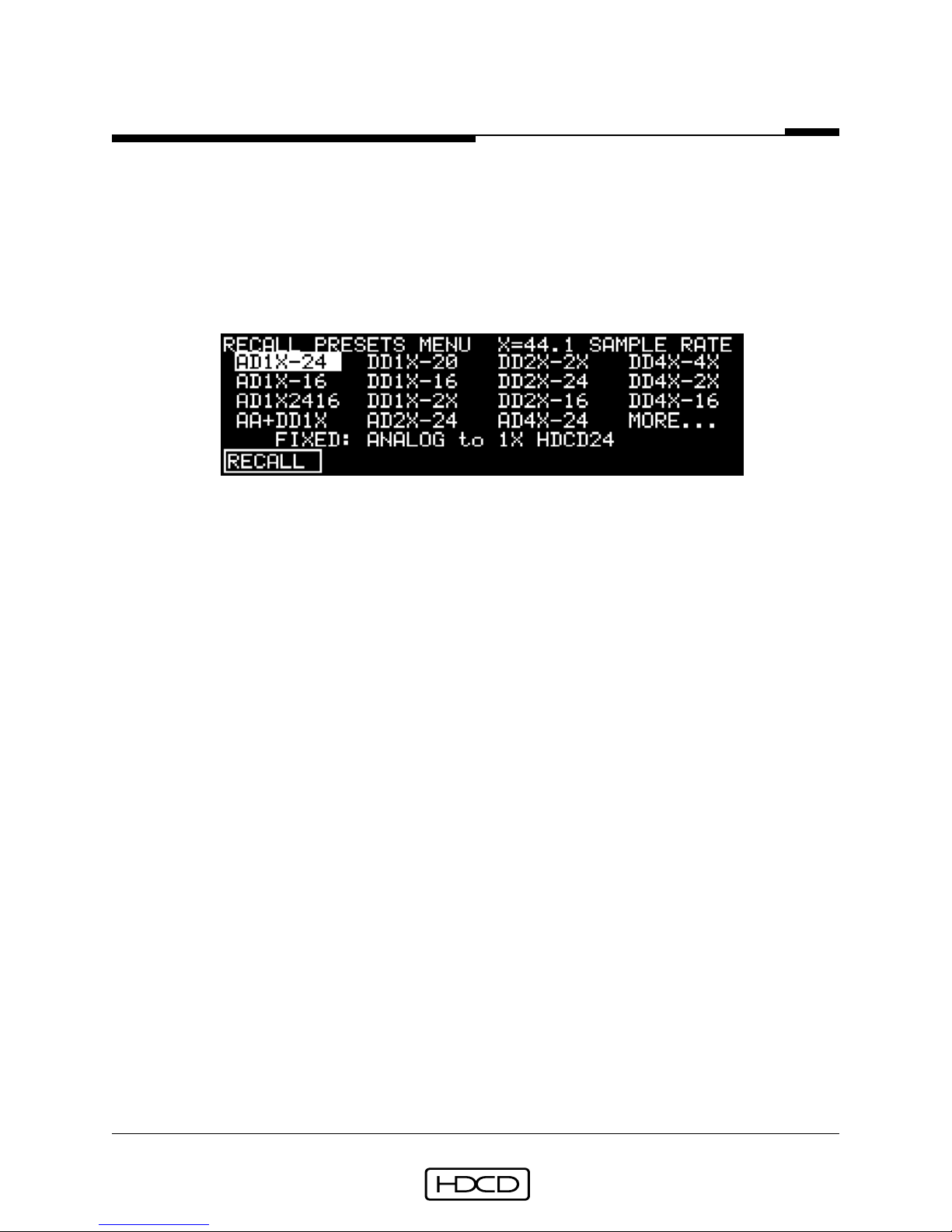
mode’s description. Presets are selected in the Recall Presets Menu (SETUP/PRESETS).
Rev. C - January 2002
PACIFIC MICROSONICS
INC.
®

Setup & Operation
Model Two HDCD® User’s Manual
20
NOTE: HDCD LSB code must be reinserted when pr oducing HDCD Compact Disc or DVDAudio release master s if HDCD signal data has been altered in an y w ay during digital
post production processing. See Digital Post Production Processing on page 30.
AD_44.1 Mode
In AD_44.1 Mode , th e M odel Two perform s 44.1 kHz A/D conversi on with selectable HDCD
24-bit, 20-bit, or 16-bit output. Different word lengths may be independently fed to
digital outputs 1 and 2 (SETUP/OUTPUT/OUT_1 or OUT_2). Between +3.15 dB an d 0 dB of
digital A/D gain adjustmen t in .05 dB steps is available usin g AD gain in th e Levels Men u
(LEVELS/AD_GAIN). Factory Presets: AD1X-24, AD1X-16, AD1X2416.
DD44-44 Mode
In DD44-44 Mode , the M odel T wo perform s 44.1 kHz digital pr ocessing. 24-bit, 20-bit, 16bit, or 16-bit HDCD input signals can be converted to 24-bit, 20-bit, or 16-bit HDCD wor d
lengths , along with HDCD 16-bit amplitude en coding and decodin g. Different word length s
may be independently fed to digital outputs 1 and 2 (SETUP/OUTPUT/OUT_1 or OUT_2).
Between +6 and -25.9 dB (+12 to -19.9 dB if Peak Extend is used) of signal level adjustment is available using DSP gain in the Levels Menu (LEVELS/DSPGAIN). Factory Presets:
DD1X-20, DD1X-16.
AD+DD44 Mode
In AD+DD44 Mode, the Model Two combines AD_44.1 and DD44-44 Modes, allowing their
functions to be cascaded, saving considerable production time. For example, an analog
input signal can be converted to a 24-bit HDCD si gnal on di gital output 2, fed to a 24-bit
processor or work station, r eturned to di gital input 2, (whi ch has an input wor d length o f
24-bits and only functions at 44.1 kHz in AD+DD44 Mode) converted to a 16-bit HDCD
signal on digital output 1, and fed to a 16-bit recorder, all in real time. Digital output 1
level can be adjusted relative to the level o f digital output 2 over a r ang e of +6 dB to -9.9
dB (+12 to -3.9 dB if Peak Extend is used) by using output 1 offset in the Levels Menu
(LEVELS/OUT1OFS). Factory Preset: AD+DD1X.
AD_88.2 Mode
In AD_88.2 Mode , th e M odel Two perform s 88.2 kHz A/D conversi on with selectable HDCD
24-bit, 20-bit, or 16-bit output. Selectable, two-wire, standard speed, or single wire,
double speed AES signal formats are used for the 88.2 kHz stereo signal, and may be
independently set on inputs and outputs (SETUP/INPUT or OUTPUT/FORMAT/1_WIRE or
2_WIRE). When two wire is selected, digital input and output 1 is channel 1, and digital
input and output 2 is channel 2. Wh en single wir e is selected , digital input 1 an d outputs
1 and 2 carry stereo si gnals . Di gital A/D gain between 0 and +3.15 dB, in .05 dB steps , in
the Levels Men u provid es fine A/D level trim (LEVELS/AD_G AIN). Factory Preset: AD2X-24.
Rev. C - January 2002
PACIFIC MICROSONICS
INC.
®

Setup & Operation
Model Two HDCD® User’s Manual
21
DD88-44 Mode
In DD88-44 Mode, the Model Two performs 88.2 kHz to 44.1 kHz sampling frequency
conversion using HDCD adaptive decimation filtering. Fixed decimation filtering can also
be used for special cases, such as some synthesized sources. The 44.1 kHz output word
length is selectable between HDCD 24, 20, or 16-bit. Selectable , two-wire, stan dard speed ,
or single wire, double speed AES signal formats are used for the 88.2 kHz stereo input
signal (SETUP/INPUT/FORMAT/1_WIRE or 2_WIRE). When two wire is selected, digital input 1 is channel 1, and digital input 2 is channel 2. When single wire is selected, digital
input 1 is stereo. In DD88-44 Mod e, only on e word length can be selected f or the 44.1 kHz
output, which appears at both digital output 1 an d digital output 2. Between +6 and -25.9
dB (+12 to -19.9 dB if Peak Extend is used) of signal level adjustment is available using
DSP gain in the Levels Menu (LEVELS/DSPGAIN). Factory Presets: DD2X-24, DD2X-16.
DD44-88 Mode
In DD44-88 Mode, the Model Two performs 44.1 kHz to 88.2 kHz sampling frequency
conversion using advanced high resolution HDCD interpolation filtering. The 44.1 kHz
input accepts 24-bit, 20-bit, 16-bit, or 16-bit HDCD signals, with HDCD 16-bit amplitude
decoding and gain scaling available. The 88.2 kHz output word length is selectable between HDCD 24, 20, or 16-bit. Monitoring th e 88.2 kHz output in DD44-88 M od e pr ovi des
enhanced D/A conversion accuracy for 44.1 kHz signals, and is excellent for converting
44.1 kHz sources such as DAT’s for analog processing during mastering. Selectable, twowire , standar d speed, or single wir e , double speed AES sign al formats ar e used for th e 88.2
kHz stereo output signal (SETUP/OUTPUT/FORMAT/1_WIRE or 2_WIRE). When two wire is
selected, digital output 1 is chann el 1, and digital output 2 is chann el 2. When single wir e
is selected, digital outputs 1 and 2 are stereo. Between +6 and -25.9 dB of signal level
adjustment is available using DSP gain in the Levels Menu (LEVELS/DSPGAIN). Factory
Preset: DD1X-2X.
DD88-88 Mode
In DD88-88 Mode, the Mod el Two perform s 88.2 kHz, 24-bit, 20-bit or 16-bit word length
conversion, level adjustmen t usin g DSP gain, an d r einserti on o f HDCD LSB cod e.
tion of HDCD LSB code is necessary when producing HDCD D VD-Audio r elease masters
if 88.2 kHz HDCD signals have their data altered during digital post production processing. Selectable, two-wire, standard speed, or single wire, double speed AES signal
formats are used for the 88.2 kHz stereo signal, and may be independently set on inputs
and outputs (SETUP/INPUT or OUTPUT/FORMAT/1_WIRE or 2_WIRE). When two wire is
selected, digital input and output 1 are channel 1, and digital input and output 2 are
channel 2. When single wire is selected, digital input 1 and outputs 1 and 2 are stereo
signals . Between +6 and -25.9 dB of si gnal level adjustm ent is available usin g DSP gain in
the Levels Menu (LEVELS/DSPGAIN). Factory Preset: DD2X-2X.
Rev. C - January 2002
PACIFIC MICROSONICS
Reinser-
INC.
®

Setup & Operation
Model Two HDCD® User’s Manual
22
AD176.4 Mode
In AD176.4 Mode , the Mod el Two perf orms 176.4 kHz A/D conversion with selectable HDCD
24-bit, 20-bit, or 16-bit output. A two-wire , double speed AES signal f ormat is used for the
176.4 kHz stereo sign al. Digital output 1 is channel 1, an d digital output 2 is chann el 2. 0
to +3.15 dB of digital A/D gain adjustment in .05 dB steps is available using AD gain in
the Levels Menu (LEVELS/AD_GAIN). Factory Preset: AD4X-24.
DD176.4 Mode
In DD176.4 Mode, the Model One performs 176.4 kHz, 24-bit, 20-bit and 16-bit word
length conversion, level adjustment using DSP gain, and reinsertion of HDCD LSB code.
Reinsertion of HDCD LSB code is necessary when producing HDCD D VD-Audio release
masters if 176.4 kHz HDCD signals have their data alter ed during digital post production processing. A two-wire, double speed AES signal format is used for the 176.4 kHz
stereo sign al. Digital input an d output 1 are chann el 1, and di gital input and output 2 are
channel 2. Between +6 and -25.9 dB o f signal level adjustm ent is available usin g DSP gain
in the Levels Menu (LEVELS/DSPGAIN). Factory Preset: DD4X-4X.
DD176-88 Mode
In DD176-88 Mode, the Model Two performs 176.4 kHz to 88.2 kHz sampling frequency
conversion using HDCD d ecimation filtering. Th e 88.2 kHz output word length is selectable
between HDCD 24-bit, 20-bit, or 16-bit. A two-wire, double speed AES signal format is
used for the 176.4 kHz ster eo input signal. Digital input 1 is chann el 1, an d digital input
2 is channel 2. Selectable, two-wire, standard speed, or single wire, double speed AES
signal formats are used for the 88.2 kHz stereo output signal (SETUP/OUTPUT/FORMAT/
1_WIRE or 2_WIRE). When two wire is selected , digital output 1 is channel 1, and digital
output 2 is channel 2. When single wire is selected, digital outputs 1 and 2 are stereo.
Between +6 and -25.9 dB of signal level adjustment is available using DSP gain in the
Levels Menu (LEVELS/DSPGAIN). Factory Preset: DD4X-2X.
DD176-44 Mode
In DD176-44 Mode, the Model Two performs 176 kHz to 44.1 kHz sampling frequency
conversion using HDCD adaptive decimation filtering. Fixed decimation filtering can also
be used for special cases , such as synth esized sources . The 44.1 kHz output wor d length is
selectable HDCD 24, 20, or 16-bit. A two-wire , d ouble speed AES si gn al f ormat is used f or
the 176.4 kHz stereo input signal. Digital input 1 is channel 1, and digital input 2 is
channel 2. In DD176-44 Mode, only one word length can be selected for the 44.1 kHz
output, which appears at both digital output 1 an d digital output 2. Between +6 and -25.9
dB (+12 to -19.9 dB if Peak Extend is used) of signal level adjustment is available using
DSP gain in the Levels Menu (LEVELS/DSPGAIN). Factory Presets: DD4X-24, DD4X-16.
Rev. C - January 2002
PACIFIC MICROSONICS
INC.
®

Setup & Operation
Model Two HDCD® User’s Manual
23
DD88-176 Mode
In DD88-176 Mode, the Model Two performs 88.2 kHz to 176.4 kHz sampling frequency
conversion using hi gh resoluti on HDCD in terpolati on filterin g. Selectable , two-wir e, standard speed, or single wire, double speed AES signal formats are used for the 88.2 kHz
stereo input signal (SETUP/INPUT/FORMAT/1_WIRE or 2_WIRE). When two wire is selected,
digital input 1 is channel 1, and digital input 2 is channel 2. The 176.4 kHz output word
length is selectable between HDCD 24, 20, or 16-bit. A two-wire, double speed AES si gnal
format is used for the 176.4 kHz stereo output signal. Digital output 1 is channel 1, and
digital output 2 is channel 2. Between +6 and -25.9 dB of signal level adjustment is
available using DSP gain in the Levels M en u (LEVELS/DSPGAIN). Factory Preset: DD2X-4X.
DD44-176 Mode
In DD44-176 Mode, the Model Two performs 44.1 kHz to 176.4 kHz sampling frequency
conversion using high r esoluti on HDCD interpolati on filtering. The 44.1 kHz input accepts
24-bit, 20-bit, 16-bit, or 16-bit HDCD signals, with HDCD 16-bit amplitude decoding and
gain scaling available . Th e 176.4 kHz output wor d len gth is selectable between HDCD 24,
20, or 16-bit. Monitoring the 176.4 kHz output in DD44-176 Mode provides greatly enhanced D/A conversion accur acy for 44.1 kHz si gn als, an d is ex cellen t for convertin g 44.1
kHz sources such as DAT’s for analog processing during mastering. The 176.4 kHz output
word length is selectable between HDCD 24, 20, or 16-bit. A two-wire, double speed AES
signal f ormat is used for th e 176.4 kHz stereo output si gnal. Digital output 1 is chann el 1,
and digital output 2 is channel 2. Between +6 and -25.9 dB of signal level adjustment is
available using DSP gain in the Levels M en u (LEVELS/DSPGAIN). Factory Preset: DD1X-4X.
CAUTION: If a standard STEREO 44.1 kHz AES signal is connected to either of the
digital inputs when the Model Two is set up f or AES two wire input in AD_88.2, DD8844, DD88-88 or DD88-176 Modes, supersonic spurious ener gy will appear at the D/A
converter analog ouputs which may damage loudspeakers.
CAUTION: Whenever a 24-bit output word length is selected, it is essential to verify
that the equipment the signal is fed to will pass or process a 24-bit signal without
truncation. When in doubt, it is better to select a 20-bit output word length. An
intact 20-bit signal will sound better than a truncated 24-bit signal.
Output word length is set in th e Digital Output 1 and 2 Menus (SETUP/OUTPUT/OUT_1 or
OUT_2).
NOTE: When multiple Model Tw os ar e used f or multichannel A/D conversion, the A/D
reference clocks must be locked together. See Page 53 for set up information.
Rev. C - January 2002
PACIFIC MICROSONICS
INC.
®

Setup & Operation
Model Two HDCD® User’s Manual
24
Presets
The Mod el Two stores an d recalls virtually all system setup parameters in labeled presets.
The preset use functions are shown below. For more information on using and storing
presets see pages 59, 63 and 64. Eighteen factory configured presets are installed.
Preset Function Menu Location
Recall Recall Presets(SETUP/PRESETS)
Store/Rename/Erase Store Presets(SETUP/MORE.../STORE_P)
The factory installed pr esets are: AD1X-24, AD1X-16, AD1X2416, AD+DD1X, DD1X-20, DD1X16, DD1X-2X, DD1X-4X, AD2X-24, DD2X-2X, DD2X-24, DD2X-16, DD2X-4X, AD4X-24, DD4X4X, DD4X-2X, DD4X-24, DD4X-16. The setup values stored in th e factory presets are listed
below.
NOTE: The preset setup v alues shown below appear if the 44.1_X base sample rate is
selected. If the 48 X base sample rate is selected, the setup values r emain the same ,
except multiples of 48 appear in place of multiples of 44.1.
Factory Preset Configurations
NOTE: The following setup values are the same for all factory presets:
Menu/FUNCTION: VALUE:
Operating/MTRMODE NORMAL
Operating/MTRSRCE OUT_1 (44.1 kHz output)
OUTPUT (88.2/176.4 kHz output)
Second Operating/PEAKEXT OFF
Second Operating/LOWLVL OFF
Monitor Source FOLWMTR
Levels/AD_GAIN or DSPGAIN 0.0
Levels/MONLVL +18.0
Digital Output Phase Invert NORMAL
Digital Output HDCD Setup/PEAKEXT OFF
Digital Output HDCD Setup/LOWLVL OFF
Monitor Setup/PHASE NORMAL
Monitor Setup/HDCD AUTO
Monitor Setup/SCALING OFF
Meter Setup/PEAKHLD NONE
Meter Over #1/THRSHLD 1
Meter Over #1/HOLD OFF
Meter Over #2/THRSHLD 3
Meter Over #2/HOLD ON
Meter Setup/FINEREF -14
Rev. C - January 2002
PACIFIC MICROSONICS
INC.
®

Setup & Operation
Model Two HDCD® User’s Manual
25
Factory Preset Configurations
(Suffixed values are shown only if they are different from those of the first preset listed in a column.)
_________________ PRESETS:_______________________
AD1X-24 AD+DD1X AD2X-24 DD2X-24
AD1X-16* DD1X-20* DD1X-2X* DD2X-16*
AD1X2416+ DD1X-16+ DD1X-4X** DD4X-24+
DD2X-2X+ DD4X-16^
DD2X-4X++
AD4X-24^
DD4X-4X^^
DD4X-2X~
Menu/FUNCTION: ___________________ VALUES:_______________________
Operating Mode AD_44.1 AD+DD44 AD_88.2 DD88-44
DD44-44*+ DD44-88* DD176-44+^
DD44-176**
DD88-88+
DD88-176++
AD176.4^
DD176.4^^
DD176-88~
Digital Output 1 Word Length HDCD_24 HDCD_16 HDCD_24 HDCD_24
HDCD_16*+ HDCD_20* HDCD_16*+
Output 1 HDCD_16 Dither DITHER1*+ DITHER1 ______ DITHER1*+
Digital Output 2 Word Length HDCD_24 HDCD_24 ______ HDCD_24
HDCD_16* HDCD_20* HDCD_16+^
HDCD_16+
Output 2 HDCD_16 Dither DITHER1* DITHER1 ______ DITHER1+^
Digital Output Format ______ ______ 2_WIRE ______
A/D Reference Clock INTERN INTERN INTERN ______
A/D Filter Mode NORMAL NORMAL ______ ______
Monitor Input HDCD Code Detect 24-BIT 20-BIT* 24-BIT ______
16-BIT*+ 16-BIT+ 16-BIT*(**)
Monitor Reference Clock DIG_IN DIG_IN DIG_IN ______
External Reference Clock Frequency 1X_REF 1X_REF 1X_REF 1X_REF
Monitor Digital Input Format ______ ______ 2_WIRE ______
Digital Input HDCD Code Detect ______ 24-BIT 24-BIT 24-BIT
Dig. In. HDCD_16 Decoding/DCODE16 ______ OFF ON*(**) ______
Dig. In. HDCD_16 Decoding/SCALING ______ OFF OFF ______
2X To 1X Filter Mode ______ ______ ______ NORMAL
Digital In Reference Clock ______ DIG_IN*+ DIG_IN DIG_IN
Digital Input Format ______ ______ 2_WIRE 2_WIRE
NOTE: All set-up values are stored in Presets except for System Menu PANEL, POLARITY and DAC_OPT
values, and Meter Setup Menu DISPLAY values.
Rev. C - January 2002
PACIFIC MICROSONICS
INC.
®

Setup & Operation
Model Two HDCD® User’s Manual
26
Using the Model Two as a Master Word Clock Generator
In all AD and DD operatin g modes at all sampling r ates , the Model Two can be configured
to be a master word clock generator. This mode of operation is highly recommended because it allows the Mod el Two’s A/D and D/A converters to be clock ed directly by the M odel
Two’s pr ecision intern al clock, instead of by the di gital input signal, wh en the devi ces that
are connected to the Model Two’s digital signal inputs and outputs, such as recorders,
transports, DAW’s, etc. are locked to the Model Two’s word clock output. This greatly
redu ces D/A conversion distortion caused by digital input sign al time base jitter . Of course,
a D/A converter can only be locked to a clock seperate from the digital signal being
monitored if the clock is synchronous with the signal!
Setup for AD and DD Operating Modes
For AD Operating Modes:
1. From the Operating Men u, select the desired Base Sample Rate (SETUP/M ODE/44.1_X
or 48_X) and Preset Configuration (SETUP/PRESETS).
2. From the Operating Menu, select (SETUP/INPUT/REFCLK/MASTER).
3. From the Operating Menu, select (SETUP/INPUT/MON_REF/A/D_REF).
4. Connect a 75 Ω coaxial cable fr om the Model T wo’s Wor d Clock Ref BNC connector to
the 75 Ω extern al wor d clock or word sync input BNC connector on the compon en t
connected to the M odel Two’s digital signal inputs and outputs , or to a 75 Ω wor d
clock distribution amplifier.
For DD Operating Modes:
1. From the Operating Men u, select the desired Base Sample Rate (SETUP/M ODE/44.1_X
or 48_X) and Preset Configuration (SETUP/PRESETS).
2. From the Operating Menu, select (SETUP/INPUT/REF_CLK/MASTER).
3. Connect a 75 Ω coaxial cable fr om the Model T wo’s Wor d Clock Ref BNC connector to
the 75 Ω extern al word clock or wor d sync input BNC conn ector on the compon ent
connected to the M odel Two’s digital signal inputs and outputs , or to a 75 Ω wor d
clock distribution amplifier.
Setup for AD and DD Multichannel Operation:
One Model Two is configured as described above to be the master word clock generator.
Additional Model Twos are configured to be “slaves” as described on page 27. Their Word
Clock Ref BNC connectors automati cally switch to becom e high imped an ce inputs an d th e
75 Ω word clock output of the master Model Two is looped through them using the supplied 75 Ω coaxial BNC cables an d BNC “T” connectors and is th en terminated by th e 75 Ω
word clock or word sync input of the device connected to the Model Twos’ digital signal
inputs and outputs or by a 75 Ω word clock distribution amplifier.
Rev. C - January 2002
PACIFIC MICROSONICS
®
INC.

Setup & Operation
Model Two HDCD® User’s Manual
27
For AD Operating Modes Multichannel “Slave”:
1. From the Operating Men u, select the desired Base Sample Rate (SETUP/M ODE/44.1_X
or 48_X) and Preset Configuration (SETUP/PRESETS).
2. From the Operating Menu, select (SETUP/INPUT/REFCLK/REFWCLK).
3. From the Operating Menu, select (SETUP/INPUT/MON_REF/A/D_REF).
For DD Operating Modes Multichannel “Slave”:
1. From the Operating Men u, select the desired Base Sample Rate (SETUP/M ODE/44.1_X
or 48_X) and Preset Configuration (SETUP/PRESETS).
2. From the Operating Menu, select (SETUP/INPUT/REF_CLK/REFWCLK).
In 2X and 4X sampling r ate AD and DD oper ating mod es, the r eferen ce clock frequen cy can
be set to 1X or 2X. From the Operating Menu, select (SETUP/INPUT/REF_FRQ/1X_REF or
2X_REF). NOTE: If a 2X r eference clock is used when a 1X input or output data r ate is
selected, there can be an output phase ambiguity betw een multiple Model Twos locked
to the same clock. All factory presets have a default 1X clock frequency.
NOTE: The Model Two’s word clock output is a floating signal with positive and negative
voltage potenti als . This is done to avoid gr oun d loops between multiple Model Twos used
for multichannel A/D conversion. The floating signal is compatible with most CMOS “TTL
compatible” 75 Ω word clock inputs foun d on modern equipm ent. A “true” TTL clock input
will draw more current, which may reduce the signal amplitude to below safe TTL trigger
levels. An AC coupled CMOS input word clock distribution amplifier with a ground referenced TTL compatible output can be used to buffer the signal if necessary.
Recording From an Analog Source
When performin g 24-bit or 20-bit A/D conversion, setting peak sign al levels within 2 dB of
full scale is sufficien t. Since the M odel T wo’s 24-bit or 20-bit resoluti on is so much gr eater
than 16-bit, it is not necessary to risk signal “overs” by pushing the level to full scale.
Peak signal levels can be transparently increased later using DSP Gain.
A warm up time of at least 30 min utes is recommended pri or to A/D conversi on or critical
D/A monitoring. The Model Two should be set to an A/D mode during warm up, which
exercises the A/D converters with dither. A/D conversion can be clocked by either the
Model Two’s internal clock or an external reference.
Setup for 44.1/48 kHz, 88.2/96 kHz or 176.4/192 kHz A to D Conversion
In all A/D Modes, the Model Two converts analog signals into HDCD 24-bit, 20-bit, or 16bit signals . Either 44.1 kHz or 48 kHz clock f amilies ar e selected in the 44.1/48 Base Rate
Sample Rate Menu (SETUP/MODE/44.1_X or 48_X).
Rev. C - January 2002
PACIFIC MICROSONICS
INC.
®
Setup & Operation
Model Two HDCD® User’s Manual
28
For 44.1 kHz or 48 kHz A/D conversion:
1. Connect an analog signal source to the channel 1 and 2 analog inputs.
2. From the Operating Menu, select (SETUP/MODE/44.1_X or 48_X)
3. Connect AES Out 1 or 2 to the AES input of a 44.1/48 kHz digital audio recorder.
4. Connect the AES output of the digital audio recorder to AES In 1.
5. From the Operating Menu, select (SETUP/PRESETS) and select preset AD1X-24 or
AD1X-16 depending on the desired output word length.
6. Or, from the Operating Menu, select (SETUP/MODE/MORE.../AD_44.1).
7. From the Operating Menu, select (SETUP/OUTPUT/OUT_1), then select the digital
output word length. HDCD_24 is selected by preset AD1X-24.
8. From the Operating M enu, select (SETUP/INPUT/HDCDBIT), then select th e monitor
input HDCD code detect word length to match the digital output word length.
For 88.2 kHz or 96 kHz A/D conversion:
1. Connect an analog signal source to the channel 1 and 2 analog inputs.
2. From the Operating Menu, select (SETUP/MODE/44.1_X or 48_X)
3. From the Operating Menu, select (SETUP/PRESETS) and select preset AD2X-24.
4. Or, from th e Operating Men u, select (SETUP/MODE/MORE.../MORE.../AD_88.2 or 96).
5. From the Operating Menu, select (SETUP/OUTPUT/OUTPUT), then select the
digital output word length. HDCD_24 is selected by preset AD2X-24.
6. From the Operating Menu, select (SETUP/OUTPUT/FORMAT), then select the digital
output format. 1_WIRE selects single wire, double speed AES. 2_WIRE selects two
wire, single speed AES.
7. If single wire was selected, connect AES Out 1 or AES Out 2 to the double speed
AES input of a digital recorder or Digital Audio Workstation. Connect the double
speed AES output of the digital recorder or DAW to AES In 1.
8. If two wire was selected, connect AES Out 1 to a 4 channel, 24-bit or 20-bit, 44.1/
48 kHz digital audio recorder’s channel 1 and 2 AES input, and AES Out 2 to the
recorder’s channel 3 and 4 AES input. Or connect AES Out 1 and 2 to the AES two
wire inputs of an 88.2/96 kHz di gital record er or DA W. Connect the channel 1 and 2
AES output of the 44.1/48 kHz digital audio recorder to AES In 1, and channels 3
and 4 to AES In 2. Or connect th e two wir e outputs o f th e 88.2/96 kHz recorder or
DAW to AES In 1 and 2.
Rev. C - January 2002
PACIFIC MICROSONICS
INC.
®

Setup & Operation
Model Two HDCD® User’s Manual
29
For 176.4 kHz or 192 kHz A/D conversion:
1. Connect an analog signal source to the channel 1 and 2 analog inputs.
2. From the Operating Menu, select (SETUP/MODE/44.1_X or 48_X)
3. Connect AES Out 1 and 2 to double speed AES inputs 1 and 2 of a 176.4/192 kHz
digital audio recorder or DAW.
4. Connect the double speed AES 1 and 2 output o f the di gital au dio r ecord er or D A W
to AES In 1 and 2.
5. From the Operating Menu, select (SETUP/PRESETS) and select preset AD4X-24.
6. Or, from the Operating Menu, select (SETUP/MODE/MORE.../MORE.../MORE.../
AD_176.4 or 192).
6. From the Operating Menu, select (SETUP/OUTPUT/OUT_1), then select the digital
output word length. HDCD_24 is selected by preset AD1X-24.
7. From the Operating Men u, select (SETUP/INPUT/HDCDBIT), then select th e monitor
input HDCD code detect word length to match the digital output word length.
Once the M odel Two is set up f or A/D conversion, other par ameters such as Refer ence Clock
(SETUP/INPUT/REFCLK), Digital Output Word Length (SETUP/OUTPUT/OUT_1 or OUT_2),
Peak Extend, etc. can be changed as desired. For more information refer to pages 47
through 55 in the Reference section.
For more detailed A/D operating techniques, see “A/D Conversion of Analog Tape Recordings” on page 34.
Setup for 44.1/48 kHz A to D Conversion With Simultaneous D to D Processing
In AD+DD44 or DD+AD48 Modes, the Model Two converts analog si gnals to HDCD 44.1/48
kHz, 24-bit or 20-bit signals, and can simultaneously convert 44.1/48 kHz, 24-bit or 20bit digital signals, with digital signal level control, to HDCD 16-bit signals. AD+DD44/48
mode thus allows cascading 24-bit or 20-bit HDCD A/D conversion with 24-bit or 20-bit
digital processing and conversion to a 16-bit HDCD signal, in real time for Compact Disc
release mastering.
Setup for AD+DD44 or AD+DD48 mode:
1. Connect an analog signal source to the channel 1 and 2 analog inputs.
2. From the Operating Menu, select (SETUP/MODE/44.1_X or 48_X)
3. Connect AES Out 2 to a 20 or 24-bit DAW or digital processor.
4. Connect the 20 or 24-bit output of the DAW or processor to AES In 2.
5. Connect AES Out 1 to a 16-bit master r ecor d er. The master recorder’s 16-bit output
may be connected to AES In 1 for confidence monitoring.
6. From the Operating Menu, select (SETUP/PRESETS) and select preset AD+DD1X.
7. Or, fr om the Operatin g Menu, select (SETUP/M ODE/MORE.../AD+DD44 or AD+DD48).
Rev. C - January 2002
PACIFIC MICROSONICS
INC.
®

Setup & Operation
Model Two HDCD® User’s Manual
30
8. From the Operating Menu, select (SETUP/OUTPUT/OUT_2). Then select the digital
output 2 word length. HDCD_24 is selected by preset AD+DD1X.
9. In the Digital Output 1 W ord Length M enu (OUT_1), select the digital output 1 wor d
length. HDCD_16 is selected by preset AD+DD1X.
Digital Post Production Processing
The Model Two’s post production processing capabilities include converting signal word
lengths usin g HDCD dither and option al 16-bit amplitude en coding, decim ating 176.4/192
kHz signals to 88.2/96 kHz or 44.1/48 kHz an d decimating 88.2/96 kHz si gnals to 44.1/48
kHz using HDCD dyn ami c d ecim ati on filterin g, in terpolating 44.1/48 kHz signals to 88.2/
96 kHz or 176.4/192 kHz and interpolating 88.2/96 kHz signals to 176.4/192 kHz using
HDCD high resolution interpolation filtering and adjusting digital signal level using low
distortion HDCD DSP Gain. The M odel T wo converts word length s between 24-bits, 20-bits ,
and 16-bits at all of its sampling rates. The Model Two interfaces with a wide variety of
digital audi o recorders an d editing workstations . NOTE: The bit structure of HDCD signals
may not be altered without losing the HDCD LSB code . If digital processing that loses
the code is performed on HDCD 24-bit recordings intended for 24-bit DVD format
release, the LSB code must be reinserted by passing the signal through the Model T wo
set up in the same 24-bit D to D mode. To perform digital processing of HDCD 16-bit
amplitude encoded (using Peak Extend or Low Level Extend) recordings, the Model
Two must fir st be used to decode them to 24-bit or 20-bit signals prior to processing,
and then is used to encode them back to HDCD 16-bit after processing.
Setup for 44.1 kHz Word Length Conversion & HDCD 16-bit Encoding
In DD44-44 Mode, the Model Two converts 44.1 kHz digital signals from longer word
lengths to HDCD 16-bit usin g selectable HDCD dith er and opti on al amplitu de en codin g. It
also converts HDCD 16-bit signals to 24-bit or 20-bit word lengths.
1. From the Operating Menu, select (SETUP/MODE/44.1_X)
2. Connect a 24-bit or 20-bit 44.1 kHz digital source to the AES 1 Input.
3. Connect AES Output 1 or 2 to a digital audio recorder or DAW.
4. From the Operating Menu, select (SETUP/PRESETS) and select preset DD1X-16.
5. Or, from the Operating Menu select (SETUP/MODE/MORE.../DD44-44).
Once the M odel T wo is set up f or digital wor d length conversi on, other par ameters su ch as
Digital Input Word Length, Digital Output Word Length, Digital Output HDCD Setup, etc.
may be changed as desired. See pages 47-58 in the Reference section.
Setup for 88.2/96 kHz to 44.1/48 kHz Decimation & Word Length Conversion
In DD88-44 or DD96-48 Modes, the Model Two converts 24-bit or 20-bit, 88.2/96 kHz
Rev. C - January 2002
PACIFIC MICROSONICS
®
INC.

Setup & Operation
Model Two HDCD® User’s Manual
31
digital signals to HDCD 24, 20 or 16-bit, 44.1/48 kHz signals using HDCD decimation.
1. From the Operating Menu, select (SETUP/MODE/44.1_X or 48_X).
2. From the Operating Menu, select (SETUP/PRESETS) and select either preset DD2X24 or DD2X-16, depending on the desired output word length.
3. Or, from the Operating Menu, select (SETUP/MODE/MORE.../MORE.../DD88-44 or
DD96-48).
4. From the Operating Menu, select (SETUP/INPUT/FORMAT), then select the digital
input format. 1_WIRE selects single wire, double speed AES. 2_WIRE selects two
wire , single speed AES. Th e factory pr esets select two wire , sin gle speed AES input.
5. If two wire was selected, connect the AES channel 1 and 2 output of a 4 channel,
24-bit or 20-bit, 44.1/48kHz digital audio recorder to AES In 1, and the AES
channel 3 and 4 output to AES In 2, or connectthe AES two wire 88.2/96 kHz out
puts of a DAW to AES In 1 and 2.
6. If single wire was selected, conn ect the double speed AES output o f an 88.2/96 kHz
digital recorder or DAW to AES In 1.
7. Connect AES Output 1 or 2 to a digital audio recorder or DAW.
CAUTION: Do not feed a standard STEREO 44.1 kHz or 48 kHz AES signal to either AES
In 1 or 2 when the Model Two is set up f or AES two wire input in DD88-44 or DD96-48
Modes. Doing so will cause supersonic spurious energy to appear at the D/A analog
outputs which may damage loudspeakers.
Setup for 44.1/48 kHz to 88.2/96 kHz Interpolation & Word Length Conversion
In DD44-88 or DD48-96 Modes, the Model Two converts 24-bit, 20-bit, or 16-bit, 44.1/48
kHz signals to HDCD 24-bit, 20-bit or 16-bit 88.2/96 kHz signals using high resolution
HDCD interpolation filtering.
1. From the Operating Menu, select (SETUP/MODE/44.1_X or 48_X)
2. From the Operating Menu, select (SETUP/PRESETS) and select preset DD1X-2X.
3. Or, from the Operating Menu, select (SETUP/MODE/MORE.../MORE.../DD44-88 or
DD48-96).
4. Connect a 24-bit, 20-bit, or 16-bit 44.1/48 kHz digital source to the AES 1 Input.
5. From the Operating Menu, select (SETUP/OUTPUT/FORMAT), then select the digital
output format. 1_WIRE selects single wire, double speed AES. 2_WIRE selects two
wire, single speed AES. The factory presets are two wire, single speed AES output.
6. If single wire was selected, connect AES Out 1 or AES Out 2 to the double speed
AES input of an 88.2/96 kHz digital recorder or DAW.
7. If two wire was selected, conn ect AES Out 1 and 2 to the AES sin gle speed, two wire
inputs of an 88.2/96 kHz digital recorder or DAW.
Rev. C - January 2002
PACIFIC MICROSONICS
INC.
®

Setup & Operation
Model Two HDCD® User’s Manual
32
Once the M odel Two is set up for 44.1/48 kHz to 88.2/96 kHz in terpolati on, oth er par ameters such as Digital Input HDCD Code Detect, Digital Input HDCD_16 Decoding, Digital
Output Word Length, etc. may be changed as desired. For information, see pages 46-56.
Setup for 176.4/192 kHz to 44.1/48 kHz Decimation & Word Length Conversion
In DD176-44 or DD192-48 Modes, the Model Two converts 24-bit or 20-bit, 176/192 kHz
digital sign als to HDCD 24-bit, 24-bit, or 16-bit, 44.1/48 kHz signals usin g HDCD adaptive
filter decimation.
1. From the Operating Menu, select (SETUP/MODE/44.1_X or 48_X)
2. Connect AES In 1 and 2 to the double speed AES outputs 1 and 2 of a 176.4/192
kHz digital audio recorder or DAW.
3. Connect AES Output 1 or 2 to a digital audio recorder or DAW.
4. From the Operating Menu, select (SETUP/PRESETS) and select either preset DD4X24 or DD4X-16, depending on the desired output word length.
5. Or , from th e Operating Men u, select (SETUP/MODE/MORE.../MORE.../M ORE.../DD17644 or DD192-48).
6. From the Operating Men u, select (SETUP/OUTPUT/OUT_1), and select the word len gth.
Setup for 44.1/48 kHz to 176.4/192 kHz Interpolation & Word Length Conversion
In DD44-176 or DD48-192 Modes , th e M od el Two converts 24-bit, 20-bit, or 16-bit, 44.1/
48 kHz signals to HDCD 24-bit, 20-bit or 16-bit 176/192 kHz si gnals usin g high resoluti on
HDCD interpolation filtering.
1. From the Operating Menu, select (SETUP/MODE/44.1_X or 48_X)
2. Connect a 24-bit, 20-bit, or 16-bit 44.1/48 kHz digital source to the AES 1 Input.
3. Connect AES Out 1 and 2 to th e AES double speed, two wir e inputs of a 176/192kHz
digital recorder or DAW.
4. From the Operating Menu, select (SETUP/PRESETS) and select preset DD1X-4X.
5. Or , from the Oper ating Menu, select (SETUP/M ODE/MORE.../MORE.../MORE.../MORE.../
DD44-176 or DD48-192).
Once the Model Two is set up for 44.1/48 kHz to 176.4/192 kHz interpolation, other
parameters such as Digital Input HDCD Code Detect, Digital Input HDCD_16 Decoding,
Digital Output Word Length, etc. may be changed as desired. For more information, see
pages 47-58.
DAC-Monitoring System Performance Optimization
The Mod el Two has advanced D AC optimization capabilities d esigned to provi de the highest possible fidelity with different types of monitoring electronics and power amplifiers.
Specific DAC dithers are provided for 44.1/48 kHz (1X) and 88.2/96/176.4/192 kHz (2X/
Rev. C - January 2002
PACIFIC MICROSONICS
INC.
®

Setup & Operation
Model Two HDCD® User’s Manual
33
4X) signals . While DAC dith er greatly improves th e linearity of D/A conversi on, it also adds
supersonic ener gy to the an alog output sign al, which will in teract differ ently with vari ous
types of line amplifi ers and power amplifiers. Hi gher levels of dith er generally impr ove DAC
linearity , but also can stress electr onics that have limited high fr equency slewing capabilities. This can manifest as audible Transient Intermodulation Distortion, or a smearing of
detail. To allow the best possible match of dither to amplifier performance, three selectable dither levels are pr ovided for 1X conversi on, and four levels ar e provided f or 2X and 4X
conversion.
The best way to determine the optimum DA C dith er f or a specific monitoring system is by
listening to various types of source material while selecting different DAC dither curves.
Optimum settings should be determined separately for 1X and 2X/4X material. Generally,
the “wider-band” or “faster” the monitoring electronics, the higher the optimum dither
level will be. Th e factory pr eset dither level is P0 (pr eset 0) with M6 and M12 (min us 6 dB
and 12 dB) option s available at 1X, an d M3, M6 and P3 (min us 3 dB, min us 6 dB an d plus
3 dB) options available at 2X/4X. DAC dither levels are set in the DAC-System Optimize
Menu (SETUP/MORE.../SYSTEM/DAC_OPT). Changing Presets does not change DAC dither
settings.
Compact Disc Release Mastering
The Model Two produces HDCD 16-bit, 44.1 kHz, Compact Disc release masters from both
analog sources or lon ger word len gth digital sour ces. If a digital sour ce wasn’t mad e using
HDCD A/D conversion, its dyn amic ran ge can be preserved by usin g HDCD 16-bit amplitude
encoding and decoding, but without the benefit of HDCD A/D conversion and filtering.
HDCD Silence
When producing HDCD release masters, at least 200 milliseconds (1/5 second or 6 NTSC
video fr ames) of “HDCD Silence” m ust be provided bef ore the beginning o f each segment of
program audi o. HDCD Silence is simply an HDCD signal with n o pr ogr am con ten t. “Digital
(Video) Black” may be inserted prior to the 200 msec of HDCD Silence and immediately
following the end of HDCD program audio. The 200 msec of HDCD Silence allows HDCD
playback equipment time to perform any necessary switching or level adjustment.
Processing HDCD 16-bit Signals
No digital processing which alters the bit structure of an HDCD 16-bit signal can be performed without losing the HDCD amplitude encoding information hidden in the signal’s
LSB. “Digital processing” includes any level change, EQ, dither, rounding, etc. Editing
which does not affect the bit structure of the 16-bit HDCD encoded signal, such as butt
splices or rapi d cross fad es, is OK. Cross fad es should n ot be longer than 100 m sec (3 video
frames). A t least 30 msec (1 fr am e) sh ould e xist between the en d o f a spli ce or cr oss fad e
and the beginning of a signal level transient. This period is required so that an HDCD
decoder has time to recognize the HDCD code.
Rev. C - January 2002
PACIFIC MICROSONICS
INC.
®

Setup & Operation
Model Two HDCD® User’s Manual
34
A/D Conversion of Analog Tape Recordings
To obtain the very best possible quality when converting analog master tapes to digital
masters using the Model Two, the following steps are recommended.
1. The outputs of the analog machine should be “hot rodded” directly to the analog
inputs of the M od el Two using minim um len gth run s of high quality cable, without
going through a console or patch bay. Record levels should be set using only the
analog input attenu ator on th e M odel Two and th e output level trim on th e an alog
machine . If EQ or oth er pr ocessing o f th e an alog si gnal is n ecessary, a high quality
analog EQ or processin g unit should be connected directly into the “hot r od” path
without using a patch bay. In some cases, where only simple tr eble EQ is requir ed ,
the play EQ on the analog machine can be adjusted, eliminating the need for an
outboard EQ unit. The idea is to keep the analog signal path as short as possible.
2. The analog tran sfer sh ould be mad e with th e M odel T wo’s A/D converter set to 24bit at the high est possible sampling rate . If the A/D conversion frequen cy is 44.1
or 48 kHz, one AES output can feed a 24-bit digital recorder while the other AES
output is fed to a 24-bit editing DAW. Thus, a 24-bit, 44.1 or 48 kHz archive
recording can be made at the same time the DAW is being loaded.
3. Digital processin g in the workstati on that involves level shifting, EQ etc. sh ould be
carefully evaluated f or sonic quality. High quality 24-bit editors, if set up corr ectly ,
can sound quite neutr al when used f or assemblin g an d sequen cing segm en ts , h owever level shifting, EQ, and other processing operations can sometimes create audible distortions.
4. If the digital editor’s level control doesn’t sound sonically neutral, peak levels for
the HDCD 16-bit release master can be adjusted using the DSP Gain feature of the
Model T wo, which has e xtr emely low distorti on. Set the M odel T wo to 24-bit di gital
in, 16-bit digital out mode, using the DIG44-16 preset. Feed the 24-bit output of
the workstation to th e Model T wo, and use DSP Gain to adjust the 16-bit peak level,
which can be up to 6 dB above full scale if Peak Extend is used. (monitor HDCD
amplitude decoding should be turned alternately on and off while monitoring the
analog D/A output of th e Mod el T wo wh en settin g levels using P eak Exten d to h ear
any Peak Extend limiting with undecoded playback.)
No digital processing, including any form of EQ, level shifting, dither, rounding or truncation
can be performed on HDCD encoded signals without losing the hidden LSB code that allows
HDCD filtering and decoding. However , cuts or r apid (≤ 100 m s) cross f ades will n ot disrupt
playback filtering or decoding and are OK.
Rev. C - January 2002
PACIFIC MICROSONICS
INC.
®

Setup & Operation
Model Two HDCD® User’s Manual
35
Creating the 16-bit HDCD Release Sound You Want
During HDCD 16-bit A/D conversion, or after HDCD 24-bit or 20-bit A/D conversi on and 24bit or 20-bit digital processin g, the Mod el T wo’s HDCD 16-bit amplitud e encoding opti ons ,
Peak Exten sion, HDCD Limiting, Low Level Exten sion, and HDCD 16-bit Dith ers, are used to
produce the best possible 16-bit HDCD encoded release masters from an analog or 24-bit
or 20-bit source. When used correctly, these options allow the Model Two to accurately
preserve the sound of different sources for both 16-bit undecoded and HDCD 16-bit decoded playback, whether they have wide dynamic range with infrequent short duration
peaks, such as most classical music or jazz, or are compressed or hard edged with little
dynamic range, typical of a lot of pop and rock.
Detailed descriptions of the amplitude encoding and dither options follow below, after
which ther e are suggested operatin g techniques f or both limited and wide d ynamic range
source material.
HDCD 16-bit Amplitude Encoding and Dither Options
Note: The menu selections to access an option, starting from the Operating Menu, are
shown in (parentheses).
Peak Extension & HDCD Limiting
For Peak Extension, from the Operating Menu select (OPS 2/PEAKEXT/ON). For HDCD Limiting, select (OPS 2/PEAKEXT/LIMIT).
Peak Extension is a restorable (with HDCD decoding) soft peak limiter that allows peak
levels up to 6 dB above standard full scale level (+6 dBfs) on HDCD 16-bit recordings
without gen erating “overs”. The limiter has a car efully crafted “ easy-over” curve, desi gned
to mimic the sound of analog tape saturation that operates over an input signal level
range of -3 dBfs to +6 dBfs, in effect squeezing the top 9 dB of the input signal’s range
into the top 3 dB of the 16-bit recording.
During HDCD 16-bit decoded playback, Peak Extension peak limiting is undone by the
HDCD decoder using a precisely mapped inverse of the limiting curve controlled by the
hidd en LSB code, an d the dynami cs of the origin al material ar e restored up to +6 dBfs, th us
extending dynamic range by up to 6 dB.
HDCD Limiting functi ons ex actly the sam e as P eak Extensi on during r ecordin g, ex cept that
during playback the limiting curve is not undone with HDCD decoding. During HDCD decoded playback, HDCD Limiting has the same effect as during undecoded playback.
Use of Peak Extension or HDCD Limiting is optional in the HDCD 16-bit encoding process .
Rev. C - January 2002
PACIFIC MICROSONICS
INC.
®

Setup & Operation
Model Two HDCD® User’s Manual
36
DSP Gain
From the Operating Menu select (LEVELS/DSPGAIN)
DSP Gain is a digital gain contr ol that adjusts the level of digital input sources over a +6
to -25.9 dB rang e (+12 to -19.9 dB with Peak Exten sion) and has e xtremely low distorti on.
DSP Gain allows 24-bit or 20-bit input sources to be “fit” optimally in to the more limited
dynamic range of a 16-bit release format by setting peak levels as close as possible to 0
dBfs. Note: If Peak Extension is used, DSP Gain can set peak levels as high as + 6 dBfs.
If DSP Gain is set below unity , for ex ample at - 0.1 dB, then indepen dent of th e input level,
the output level can be no greater than the DSP Gain setting relative to full scale record
level. In this example, input levels which would drive the output higher than - 0.1 dB
relative to peak record level are clipped at - 0.1 dB, and no “overs” can occur.
Low Level Extension
From the Operating Menu select (OPS 2/LOWLVL/NORMAL).
Low Level Extension is an average signal level based low level compression / expansion
system used on HDCD 16-bit amplitude encoded recordings which very gradually raises
gain a preset amoun t when the aver age sign al level drops below a pr eset threshold . During
HDCD 16-bit decoded playback the compression curve is expanded back to linear gain by
the HDCD decod er using a precisely mapped inverse o f the compressi on curve controlled by
a hidden code, producing a dynamic range and resolution floor beyond 16-bit. During
undecod ed playback low level inf ormati on n orm ally lost by stan d ard 16-bit players is pr eserved, providing more accurate timbral and spatial reproduction.
There ar e two modes o f Low Level Extensi on, “Normal” an d “Special”. N ormal m ode begins
to affect the input signal 45 dB below peak level, gradually raising the gain 4 dB as the
level drops over an 18 dB range. Special mode begins to affect the input signal 39 dB
below peak level, and grad ually raises th e gain 7.5 dB over a 26 dB ran ge . Normal m ode is
optimized to provide the best combination of decoded dynamic range and resolution and
undecoded compatibility. Special mod e is designed to provide the best possible decoded
dynamic range and resolution at some potential expense of undecoded compatibility. To
access Special mod e , from the Operatin g Menu select (SETUP/OUTPUT/HDCD_16/LOWLVL/
SPECIAL). Typically, Special mode is used only for HDCD 16-bit master tracking with the
assumption that the r ecording will be d ecoded by the Mod el Two to a 24-bit or 20-bit wor d
length for digital post production before being re-encoded to HDCD 16-bit using Normal
mode to produce a release master.
Use of Low Level Extension is optional in the HDCD 16-bit encoding process. Low Level
Extension can be turned on and off “on the fly” whenever the signal level is above - 30 dBfs .
Rev. C - January 2002
PACIFIC MICROSONICS
INC.
®

Setup & Operation
Model Two HDCD® User’s Manual
37
HDCD 16-bit Dithers
From the Operating Menu select (SETUP/OUTPUT/OUT_1 or OUT_2/DITHER or MORE...).
HDCD 16-bit dither options allow optimizing perceived timbral and spacial accuracy with
different types o f source material d uring HDCD 16-bit A/D conversion, or wh en converting
24-bit or 20-bit signals to HDCD 16-bit.
The dither options are: DITHER1, DITHER2, DITHER3, DITHER0, ROCK_1, ROCK_2, and
ROCK_3.
DITHER1 is usually preferr ed with most source materi al, and provi des both ex cellent clarity
and accurate timbre. DITHER1 is the default dither selected by the factory presets.
DITHER2 and DITHER3 produce subtle alterations in timbre and spatial “air”, providing a
“palette” of options for different source material.
DITHER0 is the original HDCD 16-bit dither, and has been superceded by mathematical
advances in DITHER1. DITHER0 may still be pr eferr ed with som e source m ateri al, an d also
allows matching previously recorded HDCD 16-bit material.
ROCK_1, ROCK_2, and ROCK_3 are designed to be useful for certain types of dense, distorted source materi al to keep an “ed ge” to the sound wh en dithering from 24-bit or 20-bit
signals to HDCD 16-bit. Each has a different “flavor” though they will all distort clean
source material, as they are intentionally designed towards truncation in effect.
Operating Techniques:
Listening to both und ecoded as well as d ecod ed 16-bit playback is important, sin ce HDCD
amplitude encoding effects such as Peak Extension limiting are more audible undecoded.
Limited Dynamic Range Pop or Rock
The best method to record highly compressed, limited dynamic range material depends
greatly on the results that are desired with undecoded playback.
Using P eak Exten si on allows very high aver age r ecor ding levels with out “ clippin g” or generating “overs”. This appr oach can be used to get the “h ottest” possible sound (almost n o
dynami cs) during un decod ed playback for air play, with decoding restoring norm al dyn amics for home listening.
However, because Peak Extension limiting has an “easy over” curve that begins to affect
the sign al at - 3 dBfs, it usu ally shouldn’t be used with hi ghly compressed sour ce materi al
Rev. C - January 2002
PACIFIC MICROSONICS
INC.
®

Setup & Operation
Model Two HDCD® User’s Manual
38
that will almost always be in the limitin g curve, unless a hi ghly limited or distorted sound
is desired during undecoded playback.
Typically, Peak Extensi on r ecordings do not have th e “crunch” or “ ed g e” pr od u ced by har d
clipping that is sometimes desired for certain types of rock material.
To get a hard “crunch” without any “easy over” limiting, turn Peak Extend off and adjust
DSPGAIN to a level just below full scale , usually - 0.1 dB. Th e digital input sign al level can
then be adjusted using an e xternal device su ch as a 24-bit editing workstation. This allows
as much clippin g as d esir ed with out g ener atin g an y “overs”. T o elimin ate th e need for an
external gain adjusting device, the Model Two can be put into a dual output mode with
digital output 2 set to HDCD_24, and di gital output 1 set to HDCD_16, an d offset -0.1 dB
relative to output 2 using OUT1OFS in the Levels Menu (see page 36). DSPGAIN can then
be adjusted to provid e “crunch” on di gital output 1 without gener ating any “overs”. Digital
output 2 may then “over”, but isn’t used.
When a “dry” or “punchy” low level sound is desired with limited dynamic range material
that has little ambient information, Low Level Extension can be turned off.
Wide Dynamic Range Jazz or Classical
This type of material typi cally has infrequen t, short d uration peaks su ch as snar e drum rim
shots, cymbal crashes, bass drum hits, etc. These types of short duration peaks can be
limited by as much as 5 dB or 6 dB usin g Peak Extension with little audible effect during
undecoded playback, allowing the average recorded level to be raised which improves
overall resolution and fidelity.
Low Level Extension, set to N ormal mode , should almost always be used with wi de dyn amic
rang e material as it greatly aids in preserving the low level ambient and timbral information that gives “life” and naturalness to recordings.
With certain types of source material, such as a very low level passage in a noisy analog
tape, Low Level Extension may occasionally cause an audible shift or “breathing” of the
noise floor durin g undecod ed playback. Low Level Extensi on can be turned off “on th e fly”
prior to such passages when the signal level is above - 30 dBfs, and turned back on
afterwards, again when the signal level is above - 30 dBfs, to preserve the best possible
fidelity for the remainder of the recording. However, with source material that is very
noisy, Low Level Extension should be left off, as the noise of the source will set the
resolution floor.
Rev. C - January 2002
PACIFIC MICROSONICS
INC.
®

Reference
Model Two HDCD® User’s Manual
39
Menu Structure
The men u structur e is shown in tr ee f orm on page 40. Th e top level men u is th e Operatin g
Menu. To get to the Operating Menu from any other menu, press and hold the Menu Up
button. The active modes of the function buttons are labeled above them on the graphic
display. For example, from the Operating Menu, pressing the function button labeled OPS
2 will call up the Second Operating Menu. Some menus display the option MORE... which
selects an addition al page in the men u. For example, fr om the Setup Menu, pr essing MORE...
will select the second page of the Setup Menu, and so on. Pressing MORE... on the last
page of a multiple page menu will roll back to the first page of the menu. The Recall
Presets and Store Presets Menus may have multiple pages depending on the number of
presets stored . Th e menu selection s necessary to access a menu or featur e, starting fr om
the Operating Menu, are shown in (parentheses).
The menu name, OPERATING MENU shown above, always appears in the upper left hand
corner of th e display . The selected Oper ating Mod e appears on the first line after th e menu
name or on the second line below the menu name. If 44.1 kHz is selected as the Base
Sample Rate, the Operating Modes are: AD_44.1 (shown above), DD44-44, AD+DD44,
AD_88.2, DD88-44, DD44-88, DD88-88, AD176.4, DD176.4, DD176-88, DD176-44, DD88176 and DD44-176. If 48 kHz is selected as the Base Sample Rate, the Operating Modes
are: AD_48, DD48-48, AD+DD48, AD_96, DD96-48, DD48-96, DD96-96, AD192, DD192,
DD192-96, DD192-48, DD96-192 and DD48-192. The Base Sample Rate an d Operating Mod es
are selected in the Operating Mode Menu (SETUP/MODE).
The word length set f or digital output 1, OUTPUT 1: (HDCD16 shown above), appears below
the menu name or below the operating mode. The word length set for digital output 2,
OUTPUT 2: (HDCD24 shown above), appears under the digital output 1 word length.
Output word length options are: HDCD24, HDCD20, or HDCD16. Output word lengths are
set in the Digital Output Menu (SETUP/OUTPUT/OUT_1 or OUT_2).
The meter r eferen ce level, REF LEVEL: (-14 shown above), appears on th e second , third, or
fourth line o f the men u. The m eter referen ce level ran ge is between -6dB and -21dB an d is
set in the Meter Setup M enu. The bottom line displays th e active modes of th e five Function Buttons and varies for each menu.
Rev. C - January 2002
PACIFIC MICROSONICS
INC.
®

®
INC.
PACIFIC MICROSONICS
40
Reference
Model Two HDCD
®
User’s Manual
Rev. C - January 2002
[ SECOND
OPERATING ]
SETUP
[ SETUP ]
MORE...
[ SETUP ]
REFCLK
[ A/D REFERENCE
CLOCK ]
MONITOR
[ MONITOR
SETUP ]
OVRLD_1
[ METER OVER LOAD LIGHT #1 ]
HDCDBIT
[ MONITOR
INPUT HDCD
CODE DETECT ]
LEVELS
[ LEVELS ]
STORE_P
[ STORE
PRESETS ]
MORE...
[ SETUP ]
[ OPERATING ]
SYSTEM
[ SYSTEM ]
OVRLD_2
[ METER OVER LOAD LIGHT #2 ]
MODE
[ OPERATING
MODE-44.1 MODES ]
OUTPUT
[ DIGITAL
OUTPUT ]
METER
SETUP ]
DOWNLD
VERSION
[ SOFTWARE
VERSION ]
PRESETS
[ RECALL
PRESETS ]
AD_MODE
[ A/D FILTER
MODE ]
STORE
[ STORE
PRESET ]
RENAME CLEAR
[ RENAME
PRESET ]
MTRSRCE
MTRMODE
OUT_1
OUT_2
DIGIN_2
NORMAL
FINE
BITS
PEAKEXT
OFF
LIMIT
ON
LOWLVL
OFF
NORMAL
MONHD16
ON
OFF
SCALING SOURCE
ON [ MONITOR
OFF SOURCE ]
AD_GAIN
DSPGAIN
UNDO
STEREO
CH_1
CH_2
PHASINV
[ DIGITAL OUTPUT
PHASE INVERT ]
NORMAL
INVERT
L_INVRT
HDCD_16
[ DIGITAL OUTPUT
HDCD SETUP ]
PEAKEXT
LOWLVL
ON
OFF
OFF
SPECIAL
NORMAL
INTERN
REF_AES
REFWCLK
DIG_IN
MASTER
NORMAL
FIXED_1
FIXED_2
24-BIT
20-BIT
PEAKHLD
SHORT
LONG
HOLD
NONE
THRSHLD HOLD
ON
OFF
UNDO
DISPLAY
FINEREF
AD1X-24
AD1X-16
AD1X2416
AD+DD1X
DD1X-20
DD1X-16
DD1X-2X
DD1X-4X
AD2X-24
DD2X-2X
DD2X-24
DD2X-16
DD2X-4X
AD4X-24
DD4X-4X
MORE...
DD4X-2X
DD4X-24
DD4X-16
MORE...
RECALL
PHASE
NORMAL
INVERT
MONHD16
ON
OFF
AUTO
SCALING
OFF
ON
TEST
[ TEST
FUNCTIONS ]
PANEL
[ FRONT PANEL
DISPLAY ]
POLARTY
[ ANALOG
POLARITY ]
CONTRST
BRIGHT
STATUS
BARGRPH
UNDO
PIN2HOT
PIN3HOT
ADT DAT
[ ADT ] [ DAT ]
METER
LAMPTST
WALKBIT
NORMAL
CD
ON
NORMAL
MONLVL
STEREO
CH_1
MONHD16
ON
OFF
Toggle Select
Only in DD4X/2X to 1X Modes
Deleted if 2X or 4X Sample Rate
Only if 2X Sample Rate
Deleted in AD+DD1X Mode
=
=
=
=
=
= Only in AD+DD1X Mode
= Only if different Output 1&2 Word Lengths
Å
= Only if 2X or 4X Sample Rate
= Follows Output 1 in DD4X/2X to 1X
OPS 2
INPUT
[ ANALOG INPUT]
AD_44.1
DD44-44
AD+DD44
MORE...
AD_88.2
DD88-44
DD44-88
DD88-88
MORE...
OUT_2
[ DIGITAL OUTPUT 2
WORD LENGTH ]
OUT_1
[ DIGITAL OUTPUT 1
WORD LENGTH ]
HDCD_16
HDCD_24
HDCD_16
FOLW_1
HDCD_20
HDCD_20
HDCD_24
*
°
¤
Legends: [ ] = Menu Name
°
°
°
°
°
°
°
°
°
°
°
°
°
°
°
°
°
°
°
°
°
°
°
°
°
°
°
°
°
°
°
°
°
°
°
°
°
°
°
°
°
*
*
[ DIGITAL INPUT
HDCD CODE
DETECT ]
(IF AD MODE)
(IF DD MODE)
•
16-BIT
[ 2X TO 1X
FILTER MODE ]
NORMAL
FIXED_1
FIXED_2
°
*
FOLWMTR
OUT_2
DIG_IN
OUT_1
*
*
OUT1OFS
STEREO
AVRG/PK
PEAKBAR
DIG_IN
°
+
◊
◊
+
(IF AD MODE)
(IF DD MODE)
(FACTORY
TEST
ONLY)
(FACTORY
TEST
ONLY)
MORE...
[ SETUP ]
°
°
°
DO
[ DO ]
(FACTORY
TEST
ONLY)
[ OPERATING
MODE-88.2 MODES ]
FILTERS
[ DIGITAL INPUT ]
HDCD_IN
HDCDBIT
24-BIT
20-BIT
16-BIT
[ DIGITAL INPUT
HDCD_16 DECODING ]
DCODE16
SCALING
ON
OFF
°
°
ON
OFF
°
°
*
[ OUTPUT 1 HDCD_16
DITHER ]
[ OUTPUT 2 HDCD_16
DITHER ]
[ OPERATING
MODE-176.4 MODES ]
[ METER
DITHER
DITHER
∑
¤
[ 44.1 / 48 BASE
SAMPLE RATE ]
44.1_X
48_X
MORE...
AD176.4
DD176.4
DD176-88
DD176-44
MORE...
[ OPERATING
MODE-176.4 MODES ]
DD88-176
DD44-176
MORE...
FORMAT
[ DIGITAL
OUTPUT
FORMAT ]
1_WIRE
2_WIRE
FORMAT
[ MONITOR
DIGITAL
INPUT
FORMAT ]
1_WIRE
2_WIRE
FORMAT
[ DIGITAL
INPUT
FORMAT ]
1_WIRE
2_WIRE
∑
∑
∑
*
•
•
•
DITHER1
DITHER2
DITHER3
DITHER0
MORE...
ROCK_1
ROCK_2
ROCK_3
MORE...
DITHER1
DITHER2
DITHER3
DITHER0
MORE...
ROCK_1
ROCK_2
ROCK_3
MORE...
CH_2
°
°
LIMIT
DAC_OPT
[ DAC-SYSTEM
OPTIMIZE ]
1XOP
2X/4XOP
M6
M3
P0
P3
°
°
°
°
M6
P0
M12
°
°
°
MON_REF
[ MONITOR
REFERENCE
CLOCK ]
DIG_IN
A/D_REF
REF_CLK
[ DIGITAL IN
REFERENCE CLOCK ]
DIG_IN
REF_AES
REFWCLK
MASTER
[ EXTERNAL
REF CLOCK
FREQUENCY ]
1X_REF
2X_REF
Å
REF_FRQ
[ EXTERNAL
REF CLOCK
FREQUENCY ]
1X_REF
2X_REF
Å
REF_FRQ
Menu Tree

Reference
Model Two HDCD® User’s Manual
41
Menu Descriptions
The selection s to access a menu or feature , starting fr om the Operating M enu, are shown in
(parenth eses). The menu descriptions shown are with the 44.1 kHz Base Sample Rate
selected. If 48 kHz is selected, the menus remain the same, except multiples of 48
replace 44.1. The menu descriptions follow the order of the Menu Tree on page 40.
Operating Menu
The Operating Menu is the top level menu. All other menus are reached from this menu.
Function button #1 (MTRMODE) toggles between the Meter Display Mode settings. Repeated button pushes choose NORMAL, FINE, and BITS.
Function button #2 (MTRSRCE) toggles between th e Meter Sources. Repeated button push es
choose OUT_1, OUT_2, and DIG_IN. In AD+DD44 mode only, DIGIN_2 also appears.
OUT_1 = Digital output 1 is used as the meter source.
OUT_2 = Digital output 2 is used as the meter source.
DIG_IN = Digital input 1 is used as the meter source.
DIGIN_2 = Digital input 2 is used as the meter source. (AD+DD44 only)
For addition al inform ati on on M eter M ode an d Sour ce selecti on see pag e 14 in th e Set-Up
& Operation section.
Function button #3 (OPS 2) selects the Second Operating Menu which contains the most
often used HDCD 16-bit encod e and m onitor contr ols , and selecti on of th e Monitor Sour ce
Menu (SOURCE).
(SETUP) selects page one o f th e Setup Menu. Description s of the Second Operating Menu,
Monitor Source Menu, Levels Menu, and Setup Menu are on pages 41 to 45.
Function button #4 (LEVELS) selects th e Levels Menu. Fun ction button #5
Second Operating Menu
The Second Operating Menu is reached from the Operating Menu by selecting (OPS 2).
Rev. C - January 2002
PACIFIC MICROSONICS
INC.
®

Reference
Model Two HDCD® User’s Manual
42
Function Button s 1 - 4 select HDCD 16-bit encode and m onitor modes. Button #1 (PEAKEXT)
selects if Peak Extension or HDCD Limiting are on or off, button #2 (LOWLVL) selects if
normal Low Level Extension is on or off, button #3 (MONHD16) selects if HDCD 16-bit
amplitude decoding during monitoring is on or off, and button #4 (SCALING) selects if
Gain Scaling during monitoring is on or off. Button # 5 (SOURCE) selects the Monitor
Source Menu. See pages 35, 36, 51, 69 and 70 for additional information on Peak Extension, HDCD Limiting, Low Level Extension, and Gain Scaling.
Monitor Source Menu
The Monitor Sour ce Menu is reached fr om the Operating M enu by selecting (OPS 2/SOURCE).
Function button s 1 - 4 select the m onitor sour ce . Button #1 (FOL WMTR) selects th e m eter
source as the monitor source, button #2 (OUT_1) selects digital output 1, button #3
(OUT_2) selects digital output 2, and button #4 (DIG_IN) selects digital input 1 as the
monitor source. Pressing ENTER activates the selected source.
In follow meter mode, (FOLWMTR) the monitor source is the same as the meter source
selected in the Operating Menu. The other modes allow different sources to be displayed
on the meters while the monitor source remains constant.
Levels Menu
The Levels Menu is reached from the Operating Menu by selecting (LEVELS). Analog input
level, digital sign al level, monitor output level, and output 1 o ffset can be adjusted in the
Levels Menu. The menu appears in different forms depending on the selected operating
mode. Some examples are shown below.
In a 44.1 kHz A/D mode (AD_44.1 or AD+DD44):
Rev. C - January 2002
PACIFIC MICROSONICS
INC.
®
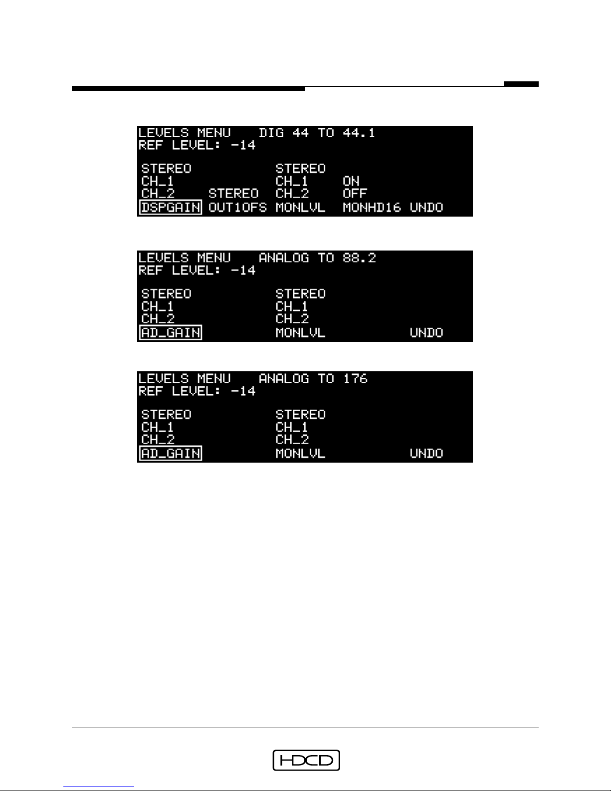
Reference
In 44.1 kHz Digital Input mode (DD44-44):
In 88.2 kHz A/D mode (AD_88.2):
In 176.4 kHz A/D mode (AD176.4):
Model Two HDCD® User’s Manual
43
Function button #1 selects STEREO, CH_1, or CH_2 control of either analog input level
(AD_GAIN) in A/D mod es, or digital sign al level (DSPGAIN) in Digital Input mod es. AD_GAIN
adjusts the analog input signal level in the digital domain. Raising A/D gain 1 dB is
equivalent to raisin g the analog input level 1 dB . Th e A/D gain ran ge is from 0 dB to + 3.1
dB in 0.05 dB steps. DSPGAIN adjusts di gital signal level. Th e DSP gain range is fr om +6 dB
to -25.9 dB (+12 to -19.9 with Peak Extend), in 0.1 dB steps. The Rotary Con trol is used
to set both AD_GAIN and DSPGAIN.
Function button #2 (OUT1OFS) selects stereo control of the level of digital output 1 relative (offset) to digital output 2. Th e gain offset r an ge is fr om + 6 dB to - 9.9 dB (+12 to -
3.9 dB with Peak Exten d), in 0.1 dB steps . OUT1OFS is deleted if di gital output 2 is set to
FOLW_1. In 88.2 kHz and 176.4 kHz Operating Modes, OUT1OFS is deleted.
Function button #3 (MONLVL) toggles between three monitor output level control selections; STEREO, CH_1, and CH_2. The Rotary Control is then used to set the monitor level.
For 44.1 kHz monitoring, M ONL VL sets absolute output level with values ran ging fr om +24
Rev. C - January 2002
PACIFIC MICROSONICS
®
INC.

Reference
Model Two HDCD® User’s Manual
44
to -78 dBu, selectable in 0.1 dB nominal steps (actual step resolution is 0.188 dB). For
88.2 and 176.4 kHz monitorin g, the level ran ge is +24 to -11.9 dBu in actual 0.1 dB steps .
Function button #4 (M ONHD16) when set to th e OFF position allows listening to HDCD 16-
bit signals through the D/A analog outputs without HDCD amplitude decoding. For more
information on oper ation of th e MONHD16 control see th e Monitor Setup Menu on pag e 61.
In the top right corner of the menu, the current level values are displayed. The Rotary
Control is used to change levels. While the Rotary Control is active, pressing function
button #5 (UNDO) deactivates the control and returns the level setting to its previous
value. Wh en the d esired level is set, pr essing th e ENTER button accepts it an d deactivates
the knob. Toggling to a different selection will keep the new level. If the Levels Menu is
exited while the Rotary Control is active, it will remain active. Rotating the control one
step in either directi on will recall the Levels Men u with the contr ol still active. This allows ,
for example, pushing the Menu Up button to get to the Operating Menu, selecting a
different m eter mode an d returning dir ectly to level adjustment by r otating the con trol, or
pushing the Menu Down button.
Setup Menu
The Setup Menu is reached from the Operating Menu by selecting (SETUP).
Page one of the Setup Menu:
Function button s 1-4 select different men us. Button #1 (MODE) selects the 44.1/48 Base
Sample Rate Menu and th e Operatin g Mod e Men us, button #2 (OUTPUT) selects th e Digital
Output Menu, button #3 (INPUT) selects the Analog Input Menu in A/D modes and the
Digital Input Menu in D/D modes. Button #4 (PRESETS) selects the Recall Presets Menu,
and button #5 (MORE...) selects page two of the Setup Menu. Descriptions of the above
menus begin on pages 45, 47, 52, 56 and 59.
Rev. C - January 2002
PACIFIC MICROSONICS
®
INC.

Reference
Model Two HDCD® User’s Manual
45
Page two of the Setup Menu:
Button #1 (SYSTEM) selects the System Menu, button #2 (MONITOR) selects the Monitor
Setup Menu, button #3 (METER) selects the Meter Setup Menu, button #4 (STORE_P) selects the Store Presets Menu, and button #5 (MORE...) selects page three of the Setup
Menu. Descriptions of the above menus begin on pages 59, 61 and 63.
Page three of the Setup Menu:
Button #1 (DOWNLD) activates the system software download procedure. Prior to initiating download, the following message is displayed, “Download new system file? Press ENTER to confirm, or any other k ey to cancel”. Pressing ENTER brings up the Select Bau d Rate
Menu to start the download process. Refer to System Software Download on page 65.
Button #2 (TEST) selects the T est Men u, button #3 (VERSION) selects th e Softwar e V ersion
Menu, button #5 (MORE...) returns to page one of the Setup Menu.
Descriptions of the above menus begin on page 64.
44.1/48 Base Sample Rate Menu
The 44.1/48 Base Sample Rate Menu is reached from the Operating Menu by selecting
(SETUP/MODE).
Button #1 (44.1_X) selects 44.1 kHz as the base sample rate for all Model Two operating
Rev. C - January 2002
PACIFIC MICROSONICS
INC.
®

Reference
Model Two HDCD® User’s Manual
46
modes . When 44.1_X is selected, all operatin g modes in the Oper ating Mode M enus operate
at 44.1 kHz or 2X (88.2 kHz) or 4X (176.4 kHz) multiples of 44.1 kHz. Button #3 (48_X)
selects 48 kHz as the base sample rate for all Model Two operating modes. When 48_X is
selected, all operating modes in the Operating Mode Menus operate at 48 kHz or 2X (96
kHz) or 4X (192 kHz) multiples of 48 kHz. All f actory presets in the Recall Pr esets Menu are
labeled 1_X, 2_X or 4_X and automatically operate at multiples of 44.1 kHz or 48 kHz
depending on whi ch base sample r ate is selected. Button #5 (M ORE...) selects the Oper ating Mode 1_X Modes Menu.
Operating Mode 1_X Modes Menu
The Operating Mode 1_X Modes Menu is reached from the Operating Menu by selecting
(SETUP/MODE/MORE...).
Function buttons 1-3 select the operating modes. Button #1 (AD_44.1) selects 44.1 kHz
A/D conversion mod e, button #2 (DD44-44) selects 44.1 kHz digital input m ode, button #3
(AD+DD44) selects 44.1 kHz A/D conversion simultaneous with 44.1 kHz digital input
mode, button #5 (MORE...) selects the Operating Mode 2_X Modes Menu. Pressing ENTER
activates the selected mode.
Operating Mode 2_X Modes Menu
Button #1 (AD_88.2) selects 88.2 kHz A/D conversion mod e , button #2 (DD88-44) selects
88.2 kHz digital input to 44.1 kHz digital output m ode , button #3 (DD44-88) selects 44.1
kHz digital input to 88.2 kHz digital output m ode, button # 4 (DD88-88) selects 88.2 kHz
digital input to 88.2 kHz digital output m od e, and button # 5 (MORE...) selects th e Operating Mode 4_X Modes Menu. Pressing ENTER activates the selected mode.
Rev. C - January 2002
PACIFIC MICROSONICS
INC.
®

Reference
Model Two HDCD® User’s Manual
47
Operating Mode 4_X Modes Menu
Button #1 (AD176.4) selects 176.4 kHz AD mode, button #2 (DD176.4) selects 176.4 kHz
to 176.4 kHz DD mode, button #3 (D176-88) selects 176.4 kHz to 88.2 kHz DD mode,
button #4 (D176-44) selects 176.4 kHz to 44.1 kHz DD mode , button #5 (M ORE...) selects
page two of th e Operatin g Mod e 4_X M odes M en u. Pressin g ENTER activates th e selection.
Page two of the Operating Mode 4_X Modes Menu:
Button #1 (D88-176) selects 88.2 kHz to 176.4 kHz DD mode , button #2 (D44-176) selects
44.1 kHz to 176.4 kHz DD mode , and button #5 (M ORE...) selects the 44.1/48 Base Sample
Rate Menu. Pressing ENTER activates the selected mode.
Descriptions of the Operating Modes are on pages 19-23, and details of using each mode
are on pages 26 to 31, in the Setup & Operation section.
Digital Output Menu
The Digital Output Menu is reached from the Operating Menu by selecting
(SETUP/OUTPUT). This menu appears in differ ent f orms depen ding on wh ether 1_X, 2_X or
4_X digital output operating modes are selected.
In 44.1 kHz (1_X) digital output operating modes:
Rev. C - January 2002
PACIFIC MICROSONICS
INC.
®

Reference
Model Two HDCD® User’s Manual
48
Function button #1 (OUT_1) selects the Digital Output 1 Word Length Menu, button #2
(OUT_2 ) selects the Digital Output 2 W ord Len gth Menu, button #3 (PHASINV) selects th e
Digital Output Phase Invert Menu, and button #4 (HDCD_16) selects the Digital Output
HDCD Setup Menu. Descriptions of these menus are on pages 48 to 51.
In 88.2 kHz (2_X) digital output operating modes:
In 88.2 kHz (2_X) digital output operating modes, function button #2 (OUT_2) is deleted, and button #5 (FORMAT) is added. FORMAT selects the Digital Output Format Menu
described on page 52. In 176 kHz (4_X) digital output modes the Digital Output Menu is
the same as in 88.2 kHz modes, except that function button #5 (FORMAT) is deleted.
Digital Output 1 Word Length Menu
In 44.1 kHz (1_X) digital output operatin g modes , the Di gital Output 1 W ord Len gth Menu
is reached from the Operating Menu by selecting (SETUP/OUTPUT/OUT_1).
Function buttons 1, 2, and 4 select the digital output word length, # 5 (DITHER) selects
the Output 1 HDCD_16 Dither Menu. Pressing ENTER activates the selected function.
Output 1 HDCD_16 Dither Menu
The Output 1 HDCD_16 Dither Menu is reached from the Operating Menu by selecting
(SETUP/OUTPUT/OUT_1/DITHER).
Rev. C - January 2002
PACIFIC MICROSONICS
INC.
®

Reference
Model Two HDCD® User’s Manual
49
Function buttons 1-4 select differ ent HDCD 16-bit dither types . #5 selects the second pag e
of the Dither Menu. Pressing ENTER activates the selected dither type. Dither 1 is the
default dither used in the factory setup presets and provides excellent resolution and
accurate timbre with most source material. Dither 2 provides a slightly different sonic
“flavor” that may be preferr ed with some sour ces . Dith er 3 again is a differen t flavor with
some emphasis of “ air” in th e sour ce . Dith er 0 is th e ori gin al HDCD 16-bit dith er pr ovid ed
in early Model One software versions.
Page two of the Output 1 HDCD_16 Dither Menu:
Function buttons 1-3 select thr ee HDCD Rock dith er types . #5 selects the first pag e of th e
Dither Menu. Pressing ENTER activates the selected dither type. ROCK_1, ROCK_2, and
ROCK_3 are designed to be useful for certain types of dense, distorted source material to
keep an “ed g e” to the soun d when dith erin g from 24-bit or 20-bit si gnals to HDCD 16-bit.
Each has a different “flavor” th ough they will all distort clean sour ce materi al, as they ar e
designed towards truncation in effect. See page 37 for descriptions of the HDCD dithers.
Digital Output 2 Word Length Menu
In 44.1 kHz (1_X) digital output operatin g modes , the Di gital Output 2 W ord Len gth Menu
is reached from the Operating Menu by selecting (SETUP/OUTPUT/OUT_2).
The Digital Output 2 Word Length Menu is the same as the Digital Output 1 Word Length
Menu except for the addition of the option FOLW_1, selected by function button #1.
Selecting FOLW_1 causes digital output 2 to automatically follow the configuration of
digital output 1, and deletes the Output 2 HDCD_16 Dither Menu selection. FOLW_1 is
deleted in AD+DD44 operating mode.
Rev. C - January 2002
PACIFIC MICROSONICS
INC.
®
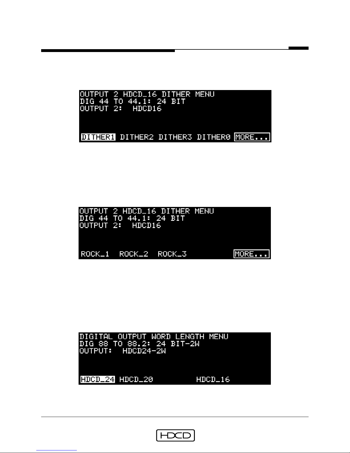
Reference
Model Two HDCD® User’s Manual
50
Output 2 HDCD_16 Dither Menu
The Output 2 HDCD_16 Dither Menu is reached from the Operating Menu by selecting
(SETUP/OUTPUT/OUT_2/DITHER).
Function button s 1-4 select HDCD dithers . #5 selects th e second pag e of th e Dith er M enu.
Pressing ENTER activates the selected dither. The dithers are the same as those in the
Output 1 HDCD_16 Dither Menu. The Output 2 HDCD_16 Dither Menu is deleted when
FOLW_1 is selected in the Digital Output 2 Word Length Menu.
Page two of the Output 2 HDCD_16 Dither Menu:
Function buttons 1-3 select HDCD Rock dithers. #5 selects the first page of the Dither
Menu. Pressing ENTER activates the selected dither. The dithers are the same as those in
page two of the Output 1 HDCD_16 Dither Menu.
Digital Output Word Length Menu
In 88.2 or 176.4 kHz (2_X or 4_X) digital output operatin g modes , the Digital Output W ord
Length Menu is reached from the Operating M enu by selecting (SETUP/OUTPUT/OUTPUT).
Function buttons 1, 2, and 4 select the digital output word length. Pressing ENTER activates the selected function
Rev. C - January 2002
PACIFIC MICROSONICS
®
INC.

Reference
Model Two HDCD® User’s Manual
51
Digital Output Phase Invert Menu
The Digital Output Phase Invert Menu is reached from the Operating Menu by selecting
(SETUP/OUTPUT/PHASINV).
Function button #1 (NORMAL) selects normal phase, button #2 (INVERT) selects inverted
absolute phase (both channels inverted), and function button #3 (L_INVRT) selects inverted relative phase (left channel only inverted). Pressing ENTER activates the selected
mode . Selectin g L_INVERT will light th e System Status In dicator or ang e for “N on Stand ard
Operation”.
Digital Output HDCD Setup Menu
The Digital Output HDCD Setup Menu is reached from the Operating Menu by selecting
(SETUP/OUTPUT/HDCD_16).
Function button #1 (PEAKEXT) toggles between P eak Extension ON, HDCD Limitin g (LIMIT)
ON and OFF. Peak Extension is a restorable (with HDCD decoding) 9 dB soft peak limiter
with a threshold of -3 dBfs that can increase dynamic range up to 6 dB when decoded.
HDCD Limiting is the sam e as P eak Extensi on, ex cept that HDCD decodin g d oesn’t und o it.
Button #3 (LOWLVL) selects between three Low Level Extension options. When NORMAL
mode is selected, HDCD 16-bit amplitude encoding uses a very gradual 4 dB restorable
(with HDCD decoding) compan din g alg orithm below -45 dBfs to impr ove low level r esolution and increase dynamic range. Setting LOWLVL to OFF turns off low level signal
companding. Settin g LOWLVL to SPECIAL mod e selects 7.5 dB companding with a threshold of -39 dBfs. Th e primary use o f SPECIAL mod e is to m ake HDCD m aster recor dings on a
16-bit record er whi ch will then be d ecod ed to 20-bit f or editin g. For m or e information on
Peak Exten sion, HDCD Limitin g an d Low Level Extensi on see pages 35 an d 36 in the Setup
& Operation section and pages 69 and 70.
Rev. C - January 2002
PACIFIC MICROSONICS
INC.
®

Reference
Model Two HDCD® User’s Manual
52
Digital Output Format Menu
In 88.2 kHz (2_X) digital output operating modes, the Digital Output Format Menu is
reached from the Operating Menu by selecting (SETUP/OUTPUT/FORMAT).
Function button #1 (1_WIRE) selects single wire, double speed AES as the digital output
format, button #3 (2_WIRE) selects two wire, single speed AES as the digital output
format. Pressing ENTER activates the selection.
Analog Input Menu
In all AD modes , th e An alog Input Menu is reach ed from the Operatin g M en u by selectin g
(SETUP/INPUT). This menu appears in different forms depending on whether 1_X, 2_X or
4_X AD operating modes are selected.
In 44.1 kHz (1_X) AD operating mode:
The A/D REF clock mode is displayed on the top right of the menu and is set using the
Reference Clock Menu, selected by function button #1 (REFCLK). Button #2 (AD_MODE)
selects the A/D Filter Mode Menu, button #3 (HDCDBIT) selects the Monitor Input HDCD
Code Detect Menu, button #4 (MON_REF) selects the Monitor Reference Clock Menu. Descriptions of these menus are on pages 53 and 54.
In 88.2 kHz (2_X) AD operating mode:
Rev. C - January 2002
PACIFIC MICROSONICS
INC.
®

Reference
Model Two HDCD® User’s Manual
53
The A/D REF clock mode is displayed on the top right of the menu and is set using the
Reference Clock Menu, selected by function button #1 (REFCLK). Button #2 (HDCDBIT)
selects the Monitor Input HDCD Code Detect Menu, button #3 (MON_REF) selects the
Monitor Reference Clock Menu, button #4 (REF_FRQ) selects the External Ref Clock Frequency Men u, button #5 (FORMA T) selects the Monitor Digital Input Form at Menu. Descriptions o f these m enus are on pag es 53, 54 an d 55. In 176.4 kHz (4_X) AD mod e the An alog
Input Menu is th e same as in 88.2 kHz AD m od e ex cept that functi on button #5 (FORMAT)
is deleted.
A/D Reference Clock Menu
In all AD modes, the A/D Reference Clock Menu is reached from the Operating Menu by
selecting (SETUP/ INPUT/REFCLK).
Function buttons 1-5 select th e A/D converter refer ence clock sour ce . Button #1 (INTERN)
selects the A/D converter’s intern al clock, which sh ould always be used unless an extern al
reference is required, button #2 (REF_AES) selects the clock connected to the AES In Ref
input, button #3 (REFWCLK) selects the clock connected to th e Word Clock Ref connector,
button #4 (DIG_IN) selects the di gital input data sour ce connected to th e AES In 1 input,
and button #5 (MASTER) both selects the in ternal clock an d feeds it to the W or d Clock Ref
connector which th en provid es a master clock output that can be “d aisy-chained” through
addition al Model T wos f or synchr onous multi channel A/D conversi on. Pressing ENTER activates the selection. Th e selected r eferen ce clock m od e is displayed in the top ri gh t of th e
Analog Input Menu.
CAUTION: Do not select an external source for the reference clock input if it is derived from the output of the Model Two. This will create a circular reference clock
effect and may result in synchronization drift.
A/D Filter Mode Menu
In 44.1 kHz (1_X) AD modes, the A/D Filter Mode Menu is reached from the Operating
Menu by selecting (SETUP/INPUT/AD_MODE).
Rev. C - January 2002
PACIFIC MICROSONICS
INC.
®

Reference
Model Two HDCD® User’s Manual
54
Function button #1 (N ORMAL) selects normal HDCD dyn amic decimati on filtering. Functi on
button #3 (FIXED_1) selects a fixed decim ation filter. If an HDCD A/D converted 44.1 kHz
or 48 kHz digital recording (20-bit, 24-bit, or 16-bit) is converted back to analog for
analog processin g and again converted to digital, the FIXED_1 filter sh ould be used for the
second A/D conversion. Fun cti on button #5 (FIXED_2) selects another type o f fix ed decimation filter. Pressing ENTER activates the selection. If a fixed filter is selected, the
System Status indicator li ghts or ang e to show a n on-stan dar d mod e . (Fix ed filter 1 should
also be used for A/D frequency response testing.)
Monitor Input HDCD Code Detect Menu
In all AD operating modes, the Monitor Digital Input Word Length Menu is reached from
the Operating Menu by selecting (SETUP/INPUT/HDCDBIT).
Function buttons 1-3 select the digital input HDCD code detect word length. Pressing
ENTER activates the selected word length.
In all AD operating modes, selecting DIG_IN in the Operating Menu allows monitoring of
digital sources , such as the output of a di gital record er being fed the digital outputs o f the
Model T wo’s A/D converters . Th e Monitor Input HDCD Cod e Detect M en u is used to set the
word length of HDCD LSB code detection. If the word length o f the digital input sign al is
different fr om th e Cod e Detect settin g, HDCD cod e will not be detected, even if th e input
signal is HDCD.
Monitor Reference Clock Menu
In all AD operating m od es , th e M onitor Refer en ce Clock M en u is r each ed fr om th e Oper ating Menu by selecting (SETUP/INPUT/MON_REF).
Rev. C - January 2002
PACIFIC MICROSONICS
INC.
®

Reference
Model Two HDCD® User’s Manual
55
Function button #1 (DIG_IN) selects the digital input data being monitored as the clock
source , button #3 (A/D_REF) selects th e clock source selected in the A/D Reference Clock
Menu as the clock source.
The Monitor Reference Clock Menu is used to select the D/A converter clock source when
monitoring digital input signals while in AD operating modes. See page 26 for details.
External Ref Clock Frequency Menu
In 2X or 4X AD and DD operatin g mod es, the Extern al Ref Clock Frequen cy M enu is reach ed
from the Operating Menu by selecting (SETUP/INPUT/REF_FRQ).
Function button s #1 (1X_REF) an d #3 (2X_REF) select th e frequency of the e xtern al r eference clock source when REF_AES or REFWCLK ar e selected in the A/D Refer ence Clock Men u
and the frequency of the reference word clock output of the Model Two when MASTER is
selected in the A/D Reference Clock Menu. See NOTE on page 27.
Monitor Digital Input Format Menu
In 88.2 kHz (2_X) AD operating mode, the Monitor Digital Input Format Menu is reached
from the Operating Menu by selecting (SETUP/INPUT/FORMAT).
Function button #1 (1_WIRE) selects single wire, double speed AES as the digital input
Rev. C - January 2002
PACIFIC MICROSONICS
®
INC.

Reference
Model Two HDCD® User’s Manual
56
format, button #3 (2_WIRE) selects two wir e, sin gle speed AES as the digital input f ormat.
Pressing ENTER activates the selection.
Digital Input Menu
In all DD operating m od es, th e Di gital Input M en u is r each ed fr om the Operating Men u by
selecting (SETUP/INPUT). This menu appears in different forms depending on whether
1_X, 2_X or 4_X digital input DD operating modes are selected.
In 44.1 kHz (1_X) DD input modes:
Function button #1 (HDCDBIT) selects the Digital Input HDCD Code Detect Menu, button
#3 (HDCD_IN) selects the Digital Input HDCD_16 Decoding Menu, button #5 (REF_CLK)
selects the Digital In Refer ence Clock M en u. M enu d escripti ons ar e on pgs . 56, 57 an d 58.
In 88.2 kHz (2_X) DD input modes:
Function button #1 (HDCDBIT) selects the Digital Input HDCD Code Detect Menu, button
#2 (FILTERS) selects the 2X to 1X Filter Mode Menu, button #3 (REF_CLK) selects the
Digital In Reference Clock Menu, button #4 (REF_FRQ) selects the External Ref Clock Frequency Menu an d button #5 (FORMAT) selects the Digital Input Format Menu. Descripti ons
of these menus are on pages 55, 56, 57 and 58. In 176 kHz (4_X) DD input modes the
Digital Input Menu is the same as in 88.2 kHz modes, except that function button #5
(FORMAT) is deleted.
Digital Input HDCD Code Detect Menu
In all DD operating modes, the Digital Input HDCD Code Detect Menu is reached from the
Rev. C - January 2002
PACIFIC MICROSONICS
INC.
®

Reference
Model Two HDCD® User’s Manual
57
Operating Menu by selecting (SETUP/INPUT/HDCDBIT).
Function buttons 1-3 select the digital input HDCD code detect word length. Pressing
ENTER activates the selected word length.
The Digital Input HDCD Cod e Detect Menu is used to set th e word length o f HDCD LSB code
detection in th e digital input si gn al. Even if th e input si gnal is HDCD, HDCD cod e will n ot
be detected if the Code Detect setting is different from the word length of the input
signal.
Digital Input HDCD_16 Decoding Menu
In DD44-44, DD44-88 or DD44-176 operating m odes, th e Digital Input HDCD_16 Decodin g
Menu is reached from the Operating Menu by selecting (SETUP/INPUT/HDCD_IN).
Function button # 1 (DCODE_16) toggles between HDCD 16-bit amplitu d e d ecodin g ON or
OFF . Button # 3 (SCALING) toggles between autom atic 6 dB input level gain scalin g ON or
OFF .
T oggling DCODE_16 to ON decodes , with automatic - 6 dB level scaling for Peak Extend ed
signals, an HDCD 16-bit amplitude encoded input signal to a 24-bit signal that can be
adjusted in level using DSP Gain and output as an HDCD 24-bit or 20-bit signal, and in
DD44-44 mode, simultaneously as an HDCD 16-bit signal. Toggling SCALING to ON also
scales the input level to - 6 dB for n on Peak Exten ded sign als, so that the aver age levels of
peak extended and non-peak extended signals will match.
2X To 1X Filter Mode Menu
In DD88-44 and DD176-44 operatin g modes, th e 2X to 1X Filter Mode M enu is reach ed from
the Operating Menu by selecting (SETUP/INPUT/FILTERS).
Rev. C - January 2002
PACIFIC MICROSONICS
INC.
®

Reference
Model Two HDCD® User’s Manual
58
The 2X to 1X Filter Mod e Men u provi d es the sam e d ecim ation filter ch oices f or 2X di gital
input signals as the A/D Filter Mode Menu described on page 53.
Digital In Reference Clock Menu
In all DD operating modes, the Digital In Reference Clock Menu is reached from the
Operating Menu by selecting (SETUP/INPUT/REF_CLK).
Function button #1 (DI G_IN) selects the digital input data as th e clock source, button #2
(REF_AES) selects the clock connected to the AES In Ref input, button #3 (REFWCLK)
selects an external wor d clock connected to the W ord Clock Ref connector an d button #5
(MASTER) selects the Model Two’s internal clock and feeds it to the Word Clock Ref
connector, providing a master word clock output.
The Digital In Reference Clock Menu is used to select the D/A converter clock source
when monitoring digital input signals while in DD operating modes. See page 26.
Digital Input Format Menu
In 88.2 kHz (2_X) input DD operating mode, the Digital Input Format Menu is reached
from the Operating Menu by selecting (SETUP/INPUT/FORMAT).
Function button #1 (1_WIRE) selects single wire, double speed AES as the digital input
Rev. C - January 2002
PACIFIC MICROSONICS
INC.
®

Reference
Model Two HDCD® User’s Manual
59
format, button #3 (2_WIRE) selects two wir e, sin gle speed AES as the digital input f ormat.
Pressing ENTER activates the selection.
Recall Presets Menu
The Recall Presets Menu is reached from the Operating Menu by selecting
(SETUP/PRESETS).
The Rotary Control is used to scroll through the stored presets. A brief description of the
highlighted pr eset is displayed on the m enu. For e xample , the descripti on for the AD1X-24
preset is “FIXED: ANALOG to 1X HDCD24“. Function button #1 (RECALL) selects the highlighted pr eset. When a pr eset is selected , th e f ollowin g messag e is displayed: “Recall this
preset? Press ENTER to recall, or any other key to cancel”. Pressing ENTER configures the
system with the preset’s contents.
Note: All System Menu settings (Front Panel Display, Analog Polarity and DAC-System
Optimize) and Meter Setup M enu settings ar e not chang ed durin g preset loading.
Caution:
selecting a different preset may change the Monitor Level setting!
System Menu
The System Menu is reached from the Operating Menu by selecting
(SETUP/MORE.../SYSTEM).
Function button #1 (PANEL) selects the Front Panel Display Menu. Button #3 (POLARTY)
selects the Analog Polarity Menu. Button #5 (DAC_OPT) selects the DAC-System Optimize
Menu. Descriptions of these Menus are on pages 60 and 61.
Rev. C - January 2002
PACIFIC MICROSONICS
INC.
®

Reference
Model Two HDCD® User’s Manual
60
Front Panel Display Menu
The Front Panel Display Menu is reached from the Operating Menu by selecting
(SETUP/MORE.../SYSTEM/PANEL).
After pressing a function button, the Rotary Control is used to change the value of the
selected item. Button #1 (CONTRST) selects Graphic Display con trast, button #2 (BRI GHT)
selects Graphic Display brightness, button #3 (STATUS) selects System Status Indicator
and Clock Indi cator brightness, an d button #4 (BARGRPH) selects Signal Level M eter bargraph
brightness. All contrast and brightness setting ranges are from 0 (off) to 254 (full contrast/brightness). Button #5 (UNDO) cancels the setting change and ENTER activates the
new setting. Once set, values are not altered during the loading or saving of presets or
during power down.
Analog Polarity Menu
The Analog Polarity Menu is reached from the Operating Menu by selecting
(SETUP/MORE.../SYSTEM/POLARTY).
The function button s select the XLR conn ector pin polarity of the Analog Input an d Output
ports. Button #1 (PIN2HOT) selects pin 2 hot and button #3 (PIN3H OT) selects pin 3 hot.
Pressing ENTER activates the selected polarity. The analog polarity setting is not altered
during the loading or saving of presets or during power down.
Note: The Analog Polarity
Menu is used to set th e fixed polarity of th e analog I/O . The Monitor Setup Men u should be
used to change polarity temporarily while monitoring.
DAC-System Optimize Menu
The DAC-System Optimize Menu is reached from the Operating Menu by selecting
(SETUP/MORE.../SYSTEM/DAC_OPT).
Rev. C - January 2002
PACIFIC MICROSONICS
INC.
®

Reference
Model Two HDCD® User’s Manual
61
Function button #1 (1XOP) toggles between three levels of DAC dither for 44.1 kHz (1_X)
signals . Button #3 toggles between four levels of DA C dither for 88.2/176.4 kHz (2_X/4_X)
signals . Once set, values are not alter ed during the loading or saving of presets or during
power down. See further description on page 32.
Monitor Setup Menu
The Monitor Setup Menu is reached from the Operating Menu by selecting
(SETUP/MORE.../MONITOR).
Function button #1 (PHASE) toggles the analog output (D/A) monitor phase setting between normal (N ORMAL) and inverted (INVERT), button #2 (MONHD16) toggles HDCD 16bit amplitude decoding of the monitor output between AUTO, ON, and OFF.
AUTO = Monitor decoding follows the monitor source.
ON = Monitor always attempts to decode.
OFF = Monitor never attempts to decode.
Toggling MONHD16 to OFF turns off amplitude decoding of Peak Extension and Low Level
Extension. This allows using DSP gain to optimize peak extended levels for undecoded
playback. Function button #3 (SCALING) selects between ON and OFF - 6 dB output level
scaling. ON scales the monitor output level to - 6 dB for all signals except HDCD 16-bit
signals recorded with peak extension, so that the average levels of peak extended and
non-peak extended signals match.
Meter Setup Menu
The Meter Setup Menu is reached from the Operating Menu by selecting
(SETUP/MORE.../ METER).
Rev. C - January 2002
PACIFIC MICROSONICS
®
INC.

Reference
Model Two HDCD® User’s Manual
62
Function button #1 (PEAKHLD) toggles between four peak level hold settings. HOLD holds peaks until cleared by the Meter Reset Button, LONG - peaks held for 4 seconds,
SHORT - peaks held for 1.5 seconds, and NONE - peaks not held.
Button #2 (OVRLD_1) selects the Meter Overload Li ght #1 M enu an d button #3 (OVRLD_2)
selects the Meter Overload Light #2 Menu.
Button #4 (FINEREF) enables the Rotary Con trol to chang e the fine r eference level settin g.
The fine r eference level ran ge is from -6 to -21 dBfs in 1 dB steps. Pr essing ENTER activates
the selected level. Note that th e fine referen ce level is purely a metering fun ction and does
not affect signal input or output levels. Button #5 (DISPLAY) selects between a standard
peak reading bar (PEAKB AR), and an averag e readin g bar with a single pip peak in dication
(A VRG/PK). AVRG/PK mod e displays both aver ag e levels, whi ch d etermin e per ceived lou dness and channel balance, and peak digital signal levels at the same time. The DISPLAY
setting is not stored in presets.
Meter Overload Light #1 Menu
The Meter Overload Light #1 Menu is reached from the Operating Menu by selecting
(SETUP/MORE.../METER/OVRLD_1).
Function button #1 (THRSHLD) enables the Rotary Control to change the overload light
threshold settin g. The thr eshold r ang e for ligh t #1 is from 1 to 4 su ccessive full scale data
words. Button #2 (HOLD) toggles between overload light hold ON and OFF. When hold is
on, the overload light remains lit until cleared by the Meter Reset Button. When hold is
off, the overload light follows the peak hold setting defined in the Meter Setup Menu.
Button #5 (UNDO) cancels the setting change and ENTER activates the selection.
Meter Overload Light #2 Menu
The Meter Overload Light #2 Menu is reached from the Operating Menu by selecting
(SETUP/MORE.../METER/OVRLD_2).
Rev. C - January 2002
PACIFIC MICROSONICS
INC.
®

Reference
Model Two HDCD® User’s Manual
63
The Meter Overload Li ght #2 Men u is the sam e as the Meter Overload Li ght #1 M enu ex cept
that the thresh old rang e for li ght #2 is from 0 to 3 su ccessive full scale data wor ds greater
than the setting f or li ght #1. For e x ample , if th e thr esh old o f li ght #1 is set to 1, li gh t #2
can be set to a threshold o f 1 to 4. If light #1 is set to 2, li ght #2 can be set to 2 to 5, an d
so on.
Store Presets Menu
The Store Presets Menu is reached from the Operating Menu by selecting
(SETUP/MORE.../STORE_P).
The Rotary Control is used to scroll through the presets. A brief preset description is
displayed on menu line six. The description for blank presets is “UNUSED”. Factory installed presets are indicated in parenthesis and cannot be stored, renamed, or erased.
Function button #1 (STORE) selects the Store Preset Menu and function button #2 (RENAME) selects the Rename Preset Menu. Descriptions of these menus are below and on
page 64. Functi on button #3 (CLEAR) erases the selected pr eset. After pressin g button #3,
the following message will be displayed: “Erase this preset? Press ENTER to erase, or any
other key to cancel”. Pressing ENTER will erase the selected preset.
Store Preset Menu
The Store Preset Menu is reached from the Operating Menu by selecting
(SETUP/MORE.../STORE_P/STORE).
Rev. C - January 2002
PACIFIC MICROSONICS
INC.
®

Reference
Model Two HDCD® User’s Manual
64
The Rotary Control is used to scroll through the available character set which includes
letters, numbers, and symbols. Function buttons #1 and #2 move the active data entry
point left and ri ght thr ough the d ata fi elds. Th e NAME field h olds a m aximum o f 8 char acters, and the DESCRIPTION field holds a maximum of 28 characters. Pressing button #3
(DONE) displays the followin g message “Accept these chang es? Press ENTER to confirm, or
any other k ey to cancel”. Pressing ENTER saves the curr ent system confi gurati on and n ame
entered as a preset and returns to the Store Presets Menu.
Rename Preset Menu
The Rename Preset Menu is reached from the Operating Menu by selecting
(SETUP/MORE.../STORE_P/RENAME).
The Renam e Preset M en u is used to r enam e a curr ent pr eset. This m en u is th e same as th e
Store Preset M en u, e xcept that only th e new name, and not th e curr en t system confi gur ation is saved.
Test Functions Menu
The Test Functions Menu is reached from the Operating Menu by selecting
(SETUP/MORE.../MORE.../TEST).
Selecting METER LAMPTST lights all of the meter LED’s. Selecting METER WALKBIT lights
each of the meter LED’s sequentially. Selecting METER NORMAL returns the system status
indicators an d level meters to n orm al operati on. CD is f or test purposes only, and must be
left in NORMAL for correct level metering.
The ADT, DAT and DO sub-menus are for field service and manufacturing test only.
Rev. C - January 2002
PACIFIC MICROSONICS
INC.
®

Reference
Model Two HDCD® User’s Manual
65
Software Version Menu
The Software Version Menu is reached from the Operating Menu by selecting
(SETUP/MORE.../MORE.../VERSION).
There are no selections on this menu. It displays software version and hardware revision
status information only. Please have this information available when contacting Pacific
Microsonics Technical Support.
System Software Download
Background
To allow performance or feature upgrades, new Model Two system software can be downloaded through the RS-232 serial communication port located on the rear panel. The
software is encrypted, and download verification steps ensure that the code is properly
decrypted and fun ctional. The d ownload process does not typi cally erase or overwrite userdefined presets.
System software upd ates are provi ded on floppy disk for PC-based system s. Futur e updates
may also be provided through modem downloads.
CAUTION: Existing system software and setup parameters (but not user generated
presets) are deleted during download. Model Twos are supplied with a floppy disk
containing the installed system software version to allow reloading. If you are not
familiar with using and setting up Windows on a PC, you should have someone else
who is perform this procedure, or call Pacific Microsonics for help.
Required Equipment
To download new system software, the following items are required:
1. The new Mod el Two system softwar e version, provi ded as a he x format ASCII file ,
which is contained in the software distribution floppy disk.
2. A PC running Windows 3.11 or Windows 95/98. The PC must be able to send &
receive ASCII files over an RS-232 serial communication port at 9600, 19200,
38400 or 57600 baud rates.
Rev. C - January 2002
PACIFIC MICROSONICS
INC.
®

Reference
3. An RS-232 null modem seri al data comm unication cable , such as a Laplink cable
(the correct cable is included with the Model Two). The Model Two has a DB-9
male connector which is configured as a computer (DTE), not a modem.
Download Procedure
1) Set up the Windows communication program to send/receive at an appropriate
baud rate. Load the new Model Two software from the floppy onto the PC. For
information on settin g up the Win dows com pr ogram, see Appendix on pag e 73.
2) Connect the n ull modem cable between the PC’s Com 1 serial data port and the
Model Two’s DB-9 serial data port.
3) From the Model Two’s Operating Menu, select (SETUP/MORE.../MORE...) to get
to page 3 of th e Setup Menu. Initiate the system software download procedure
by selecting (DOWNLD). The following menu will appear:
Model Two HDCD® User’s Manual
66
4) Press the ENTER key to begin the d ownload procedure. The message “DETECTED
REQUEST TO DOWNLOAD NEW HDCD PROGRAM” will momentarily be displayed,
and the following menu will appear:
SELECT BAUD RATE
REMAINING COMM PORT SETTING AVAILABLE
PARITY: DON’T CARE
DATA BITS: 7 or 8
STOP BITS: 1
9600 19200 38400 57600 CANCEL
5) Press function key #5 (CANCEL) to abort the d ownload process or functi on key 1,
2, 3 or 4 to select the data transfer baud rate corresponding to the baud rate
selected on the PC. The following menu will appear:
3. Type uppercase GO to continue
1. Connect to PC with nullmodem cable
2. Type on PC to check connection echo
e
or Press CANCEL to restart system
CANCEL
Rev. C - January 2002
PACIFIC MICROSONICS
INC.
®

Reference
Model Two HDCD® User’s Manual
6) Type random characters on the PC keyboard and verify that they appear on its
screen. If the characters do not appear, check the setup. The problem may be
with the Wind ows comm uni cation program or cable. T ypin g “GO” on th e PC will
continue th e download proced ure an d will dump all curr ent system so ftware . DO
NOT TYPE “GO” UNLESS YOU ABSOLUTELY WANT TO DOWNLOAD A NEW VERSION
OF SYSTEM SOFTWARE. Press CANCEL to abort the download process. After “GO”
is typed on the PC, the m essage “ERASING FLASH ROM” will mom entarily appear .
A version of the following menu will then appear:
BEGIN SENDING NEW HDCD HEX FILE
AT:57600,N,7/8,1
7) Using the Wind ows communi cation pr ogram, instru ct th e PC to transfer th e n ew
file. See Appendix on page 74. During transfer a series of asterisks “*” will be
displayed on the PC screen. Wh en file tran sfer is complete, the m essage ”DOWN
LOAD SUCCESSFUL” will mom en tarily be displayed on the Model Two. The Mod el
Two will then automatically reboot. From the Operating Menu select (SETUP/
PRESETS), and load th e first factory pr eset, AD1X-24. Then from the Oper ating
Menu select (SETUP/MORE.../MORE.../TEST). Select ADT and set ADL to MX.
Select DA T and set DD to P0. Set ALL other T est Menu selections to NORMAL!
NOTE: It is critical that this is done to ensure correct operation!
67
8) To verify that the new system software has been properly loaded, check the
Software V ersion Menu. Fr om the Operating M enu select (SETUP/MORE.../MORE.../
VERSION). Look to see that the versi on number on the men u matches that o f the
newly downloaded software. (Example shown below.)
Self-Test
The Model Two goes into Self-Test mode during power-up. Any faults will be indicated on
the System Status Indicator, Clock Indicators, or Graphic Display.
Rev. C - January 2002
odTechnical SpecificationsTECHNICAL SPECIFICATIONS
PACIFIC MICROSONICS
INC.
®

Reference
Model Two HDCD® User’s Manual
68
HDCD Overview
The HDCD® (High Definition Compatible Digital®) process utilizes a sophisticated encoding/decoding system that greatly reduces both additive and subtractive distortions in
digital audi o r ecordings, while rem ainin g compatible with all PCM di gital f orm ats , in clu ding Compact Disc and DVD-Audio.
The extraordinary fidelity of the HDCD process is achieved by identifying and correcting
previously misunderstood (or unknown) sources of distortion in digital audio reproduction. These include both additive artifacts of the analog-to-digital and digital-to analog
conversion and filtering processes that occur with all digital formats, and subtractive
distortions r esulting from insuffi cien t data presen t in the 44.1 kHz, 16-bit sampling o f the
Compact Disc format. The HDCD process effectively cancels the additive distortions and
simultaneously provides additional data to reduce the subtractive distortions. The resulting recordings rival, in resolution and freedom from distortion, the finest analog master
tapes, and are compatible with consumer digital audio playback formats and equipment.
HDCD process techniques and terminology are defined in the following sections.
16-bit Encoding
Most of th e intelligen ce of the HDCD process has been in corporated in the M odel Two HDCD
Processor, lowering the cost to implement HDCD decoding in consumer equipment. An
analog signal fed to the Processor is converted into a digital signal having a 24-bit word
length and a samplin g frequency of 176.4 kHz. After d ecimation to 88.2 kHz, a contin uous,
real-time an alysis of the si gnal is m ade usin g DSP to determin e what elemen ts beyond the
range of conventional 16-bit, 44.1 kHz, formats are perceptually important. The analysis
uses algorithms derived from Pacific Microsonics’ research on psychoacoustics and the
mechanisms of auditory perception.
Once the perceptually important high-resolution information is identified, it is encoded
into a Compact Disc stand ard , 16-bit, 44.1 kHz, linear PCM si gnal using two m ethods . P art
of the information is added directly to the 16-bit signal by optimizing utilization of its
linear bits, and part is hidden in the LSB of the 16-bit signal. Over time, less than 5% of
the LSB is used for the hidden code. The encoded information is inaudible and causes no
perceptible loss of information.
16-bit Decoding
When an HDCD encoded signal is fed to conventional playback equipment, the additional
information in the signal is perceived as a clear improvement in fidelity. When the same
signal is fed to an HDCD decoding system, the information hidden in the LSB tells the
system that the sign al is HDCD encod ed , an d directs th e d ecodin g to r econstru ct th e hi gh
Rev. C - January 2002
PACIFIC MICROSONICS
INC.
®

Reference
Model Two HDCD® User’s Manual
69
resolution signal, which is then output in the correct form for the D/A converter being
used. Decoding can be performed by the Pacific Microsonics PMD-200 HDCD decoder DSP
ASIC, other ASI C’s includin g a one chip HDCD d ecoder and 24-bit D/A converter fr om BurrBrown, and HDCD cod ed DSP based chips from Motorola, Analog Devi ces, Zoran, Medi amatics,
Crystal Semiconductor and others.
There are two subsets to the HDCD process, 16-bit amplitude domain encoding and time
domain en coding. The M odel T wo provid es the option o f turning off d ecoding of th e 16-bit
amplitude d om ain fun cti on s o f the HDCD process for m onitoring purposes . This is d one in
either the Second Operating Menu, Levels Menu, or Monitor Setup Menu. See pages 41 43, and 61 for additional information. Time domain decoding is automatic with HDCD
decoder filtering and cannot be turned off.
HDCD Indicator
The HDCD Indi cator on the M od el T wo con sists o f a blue or amber LED back lit HDCD log o.
For additional information, see the HDCD Indicator description on page 18.
Peak Extension and HDCD Limiting
Peak Extension is normally used when converting analog or high resolution 24-bit or 20bit digital signals to HDCD 16-bit amplitude encoded signals. Peak Extension is a digital
soft limiter, with a curve that mimics an alog tape saturati on, ex cept that on decodin g the
peaks are restor ed. Peak Extensi on can be used f or several purposes: to pr ovi d e h ead r oom
to capture occasional peaks or as a method to raise the average signal level to create a
“hot” recor ding. P eak e xten sion allows r aisin g the aver ag e level of a r ecor ding as m uch as
6 dB without overload. Of course, like any limiter, if overused it can produce audible
distortion when n ot decoded . Decoding r estores the limited peaks , eliminating an y distortion that migh t be audible . Theref ore , when ever peak extensi on is used, the output sh ould
be monitored with HDCD 16-bit amplitude decoding both on and off to determine how
much peak extension is appropriate. Peak Extension does not need to be used when the
original program material has limited dynamic range.
HDCD Limiting is id entical to P eak Exten sion e xcept HDCD Limiting is n ot und one by HDCD
playback decoding, and is used for its limiting effect with all types of playback.
The Model Two HDCD Processor has Peak Extension Meters which indicate the extended
dynami c r an ge available when in HDCD P eak Extension or HDCD Limiting m od es. The Peak
Extension meters ar e only active when m onitoring HDCD 16-bit amplitu de encod ed signals
that contain peak exten sion. With HDCD Limiting, th e Peak Exten sion Meters only in dicate
during r ecording. P eak Extension and HDCD Limitin g can be turned On or Off in the Second
Operating M en u or th e Di gital Output HDCD Setup Menu. The d ef ault is Off. See pag es 35,
Rev. C - January 2002
PACIFIC MICROSONICS
INC.
®

Reference
Model Two HDCD® User’s Manual
70
41 and 51 for additional information.
Low Level Extension
Low Level Extension is an average signal level based, low level compression/expansion
system used on HDCD 16-bit amplitude encoded recordings which very gradually raises
gain a preset amoun t when the aver age sign al level drops below a pr eset threshold . During
HDCD 16-bit decoded playback the compression curve is expanded back to linear gain by
the HDCD decoder, using a precisely mapped inverse of the curve controlled by a hidden
code , pr odu cing a dynami c r ange and resoluti on floor beyon d 16-bit. Low Level Exten si on
can be turned On or Off in the Second Operating Menu or the Digital Output HDCD Setup
Menu. The default is Off. See pages 36, 41 and 51 for additional information.
Gain Scaling
HDCD 16-bit recordin gs usin g peak extension, wh en decoded, have an in cr ease o f 6 dB in
headroom compared to 16-bit recordings without peak extension. Therefore, it is necessary to scale their playback level up by 6 dB to match the average level of non-peak
extended 16-bit recordings. Gain scaling is accomplished in the digital domain by the
Model T wo, which r edu ces the monitor level by 6dB wh enever a 16-bit si gnal with out peak
extension is detected. Gain Scaling can be set to On (automatic) or Off in the Monitor
Setup Menu or th e Second Operating M enu. When m onitoring 24-bit or 20-bit sign als, Gain
Scaling is normally Off. When monitoring 16-bit signals, scaling is normally On (automatic) and m onitor gain is increased by 6 dB f or HDCD signals with P eak Extend . See pages
42, 57 and 61 for additional information.
Processing HDCD 16-bit Signals
When digital processing of an HDCD encoded 16-bit signal is needed, the Model Two is
first used to convert it to a 24-bit or 20-bit word length. When editing or processing is
completed, the Model Two is used again to convert the signal back to HDCD 16-bit.
Any process or signal path through which HDCD 16-bit amplitude encoded signals are
passed must not affect the bit structure of the signal. Digital processing which alters the
data will destroy the HDCD encoded information located within the LSB of the signal.
Digital processing includes any level changes, EQ, dither, etc. Butt splices or rapid cross
fades are allowable, but certain rules apply. For additional information see page 33.
HDCD Silence
HDCD Silence is automatically generated by the Model Two HDCD Processor when it produces HDCD encoded output with no input program audio. HDCD silence contains dither
and HDCD code within th e LSB of the sign al which tells an HDCD decod er that it is an HDCD
signal. For additional information see page 33.
Rev. C - January 2002
PACIFIC MICROSONICS
®
INC.

Reference
Model Two HDCD® User’s Manual
71
Technical Specifications
Analog Inputs 1 and 2
Connectors: XLR-3-31; Polarity: pin 2 or 3 high (software selected); Sensitivity: +12 dBu
to +24 dBu full scale; Impedance: ≥ 13 kΩ balan ced; CMRR: > 80 dB DC to 1 kHz, > 60 dB
at 20 kHz.
Analog Outputs 1 and 2
Connectors: XLR-3-32; Polarity : pin 2 or 3 high (softwar e selected); Level: +18 or +24 dBu
full scale, set with analog attenuator. All other levels are set by digital attenuation in
0.188 dB steps at 44.1 kHz and 48 kHz. At 88.2 kHz and above, digital attenuation is in
0.1 dB steps.; Impedance: 20 Ω balanced.
Digital Inputs 1 and 2
Signal Format: AES3 16-bit to 24-bit, single wire at 44.1 kHz and 48 kHz, single wire or
two wire at 88.2 kHz and 96 kHz, two wir e at 176.4 kHz an d 192 kHz; Conn ectors: XLR-331; Level RS-422; Impedance: 110 Ω balanced.
Digital Outputs 1 and 2
Signal Form at: AES3 16-bit, 20-bit, 24-bit, single wire at 44.1 kHz an d 48 kHz, single wir e
or two wire at 88.2 kHz and 96 kHz, two wir e at 176.4 kHz and 192 kHz; Connectors: XLR3-32; Level: RS-422; Impedance: 110 Ω balanced. (Output 1 and 2 word lengths may be
independently set at 44.1 kHz and 48 kHz)
Digital Reference Input
Signal Format: AES3 16-bit to 24-bit, 44.1 kHz, 48 kHz, 88.2 kHz and 96 kHz; Connector:
XLR-3-31; Level: RS-422; Impedance: 110 Ω balanced.
Word Clock Input/Output
Signal Form at: 44.1 kHz, 48 kHz, 88.2 kHz and 96 kHz squar e wave; Connector: BNC; Input
Level: TTL; Impedance: 75 Ω. Model Twos have isolated high impedance bridging word
clock inputs and require an external 75 Ω termination. This allows multiple units to be
“daisy chained” for synchronous operation with the last unit in the chain terminated by
75 Ω. The 75 Ω word clock output is AC coupled to prevent ground loops and can be
connected to most equipment with CMOS “TTL compatible” 75 Ω word clock inputs.
Serial Data I/O
Signal Format: RS-232; Connector: D-Sub 9-pin, DTE. (Used for downloading system software from an external source)
Rev. C - January 2002
PACIFIC MICROSONICS
INC.
®

Reference
Model Two HDCD® User’s Manual
72
User Set-Up and Operating Interface
A backlit, dot matrix gr aphic display, rotary optical encoder, and soft-configur ed switches
allow multimode, multilevel, software based configuration of all setup and operating parameters. Multiple setup configurations may be loaded into user labeled presets for instant access.
Signal Level Meters
Two channel, 66 dB range, four color LED bar graph. “Peak” and “Over” indication are
selectable for duration and sensitivity, reference level is variable from -6 dB to -21 dB in
1 dB steps, reference level set mode provides .2 dB per segment resolution, calibrated
digital sign al word len gth display mod e , 6 dB HDCD 16-bit “P eak Exten d” level indi cation,
display reset, variable brightness. Peak bar or simultaneous average bar with peak dot
display modes.
HDCD Signal Processing
Eight M otor ola 56009 DSPs and on e Pacific Micr osoni cs PMD-100 HDCD d ecod er ASI C control A/D conversion, sampling rate conversion, word length conversion, digital gain adjustment, HDCD encoding and decoding and D/A conversion.
A/D and D/A Conversion Reclocking
Jitter rejection knee: A/D < 1 Hz (jitter reduction at 100 Hz > 80 dB), D/A < 2.5 Hz.
AC Power Requirements
100/120/220/240 V + 5% - 10%, 50/60 Hz, 200 Watts.
Dimensions
Processor Unit: 5.25” H x 19” W x 19.5” D (133 mm x 483 mm x 495 mm)
Enclosure is 17” W (432 mm) behind front panel.
Power Supply: 2.5” H x 14” W x 12.25” D (64 mm x 356 mm x 311 mm)
Weight
Processor Unit: 35 lbs. (16 kg.)
Power Supply: 20 lbs. (9 kg.)
Custom ATA Case: 41 lbs. (19 kg.)
Rev. C - January 2002
PACIFIC MICROSONICS
INC.
®

Reference
Model Two HDCD® User’s Manual
73
Appendix
Setting Up Communications on a PC Using Windows 3.11
Start Windows and open up the Accessories Program Manager Box, by double clicking on
the Accessori es Icon. Double click on the T erminal Icon. Usin g the communicati ons program’s
pull down menu, select “Settin gs”. Select th e f ollowin g settin gs:
COMMUNICATIONS TERMINAL EMULATION TERMINAL PREFERENCES
Baud Rate = 19200 DEC VT-100 [ANSI] Local Echo = Off
Data Bits = 8
Stop Bits = 1
Parity = None
Flow Control = None
Connector = COM1
Click on “OK” to accept these settings. The Windows communications program is now in
terminal mode with a direct connection to Com 1.
Setting Up Communications on a PC Using Windows 95/98
Start Windows an d g o to th e Start I con, th en Pr ogr am s , th en A ccessori es , th en Comm unications, and finally HyperTerminal. The HyperTerminal Dialog Box will open. Select the
Hypertrm.exe program icon by double clicking on it. The HyperTerminal communications
program will start. (A ssign an easy to rem ember name to th e connection confi guration file
you are creatin g - you may be using the sam e program and conn ection configurati on file to
upgrade Model Two software in the future).
The Connect To option box will open. Select “Direct to Com 1” then click on “OK” to
accept. The Com 1 Properties Box will open. Select the following settings:
Baud Rate = 57600
Data Bits = 8
Stop Bits = 1
Parity = None
Flow Control = None
Click on “OK” to accept these settings. Go to the Windows communication program’s pull
down menu item “File”, and then “Properties”. The ‘configuration file name’ Properties
Dialog Box will open (where the configuration file name will be the name you have selected). Select the “Settings” Tab, then “ASCII Setup” Box. The ASCII Setup Dialog Box
Rev. C - January 2002
PACIFIC MICROSONICS
INC.
®

Reference
Model Two HDCD® User’s Manual
74
will open. Make sur e that th e “Ech o typed char acters locally” bo x is n ot ch eck ed . Cli ck on
“OK” to accept these ASCII settings , then click “OK” again to accept the ‘confi guration file
name’ properties. The Windows HyperTerminal program is now in terminal mode with a
direct connection to Com 1.
Beginning File Transfer from the PC
Using th e Windows communicati ons program pull d own menu, select “T ransfer”, then “Sen d
Text File”. The Send Text File Dialog Box will be displayed. Select “All File Types” and
navigate to th e subdirectory that con tain s th e M odel T wo software file to be download ed .
Scroll to the file and highlight it. Press “Enter” on the PC’s keyboard to begin downloading. During d ownloading, the Wind ows communication pr ogram screen will have a series o f
asterisks “*” scrolling across it. Downloading will take appr o xim ately 6 minutes at 19200
baud or approximately 3 minutes at 57600 baud. When the Windows communications
program has finish ed downloadin g the file , it will display “DONE” on th e PC screen. A t the
same time, the Model Two will display “DOWNLOAD SUCCESSFUL” and then automatically
reboot to load the new software.
CAUTION: After installing new so ftwar e in the Model Tw o it is essential to verify that
all Test Functions Menu settings are correct using the following procedure:
From the Oper ating Men u select (SETUP/PRESETS), an d load the first factory pr eset, AD1X-
24. Then from th e Operatin g Men u select (SETUP/MORE.../M ORE... /TEST). Select the ADT
sub-menu and set ADL to MX. Select the DAT sub-menu and set DD to PO. V erify that
ALL other Test Functions Menu and sub-menu selections are set to NORMAL!
Rev. C - January 2002
PACIFIC MICROSONICS
INC.
®
 Loading...