

Pacific energy z35, A Installation Manual
INSTALLATION MANUAL
INSTALLER:
Leave this manual with the appliance.
CONSUMER:
Retain this manual for future reference.
WARNING: If the information in these instructions is not followed exactly a fire or explosion
may result causing property damage, personal
injury or death.
FOR YOUR SAFETY
Installation and service must be performed by a qualified installer, service
agency or the gas supplier
WHAT TO DO IF YOU SMELL GAS
• Do not try to light any appliance.
• Do not touch any electrical Switch.
• Do not use any phone in your building.
• Immediately call your gas supplier
from a neighbour’s phone. Follow the
gas supplier’s instructions.
• If you cannot reach your gas supplier
call the fire department.
Do not store or use gasoline or other
flammable vapours and liquids in the
vicinity of this or any other appliance.
INSTALLATION
INSTRUCTIONS
This appliance is suitable for installation in a
bedroom or bed sitting room.
This appliance may be installed in an after-
market permanently located, manufactured
home (USA only) or mobile home, where not
prohibited by local codes.
This appliance is only for use with the type of
gas indicated on the rating plate. This appliance is not convertible for use with other
gases unless a certified kit is used.
Visit www. pacificenergy.net for the most recent version of this manual
MODEL: z35
SERIES: A
ZERO CLEARANCE
DIRECT VENTED GAS
FIREPLACE HEATER
z35260619-56
100001042-50
Table of Contents
WARNING:
This product
can expose you to chemicals
including ceramic bers,
which are known to the State
of California to cause cancer, and carbon
monoxide, which is known to the State of
California to cause birth defects or other
reproductive harm.
For more information go to
www.P65Warnings.ca.gov.
This warning is applicable to all
Pacific Energy Fireplace Products
Important Note for the Commonwealth
of Massachusetts .................................................... 3
Caution ....................................................................4
Safety ......................................................................5
Fireplace Dimensions ............................................. 6
Locating the Fireplace .............................................7
Framing and Finishing ............................................ 8
Framing in the z35 .................................................. 9
Framing in the z35 and Optional
Cool Wall Venting Kit .............................................. 9
Lower Opening Trim Piece ....................................11
Clearances to Combustibles .................................12
Standard Conguration .......................................12
Cool Wall Kit .......................................................12
Conguration .......................................................12
Venting Chart ........................................................ 16
Vent Terminal Minimum Clearances ......................17
Venting Conguration ........................................... 18
Vertical Termination .............................................. 19
Vertical Termination using a Duravent Terminal .. 19
Vertical Termination using an ICC Terminal ........ 19
Horizontal Termination .......................................... 20
Horizontal Termination
using a Duravent Terminal .................................. 20
Horizontal Termination using an ICC Terminal ... 20
Electrical Connection ............................................21
Wall Switch Installation ..........................................22
Home Automation ................................................ 23
Control Overview ...................................................24
Gas Valve for Conguration ...................................25
Gas valve and control module .............................25
Gas Connection .................................................... 26
Gas Supply ............................................................ 27
Gas Pressure Check ..............................................27
Gas pressure requirements .................................27
Gas Pressure Testing Procedure .......................... 29
Gas Leak Detection .............................................. 30
Lighting Instructions .............................................. 31
Panel Installation ...................................................32
Glass Bafe Installation .........................................34
Log Set Installation ................................................35
Glass Media Installation ........................................41
Door Installation/Removal .....................................42
Front Surround Installation/Removal .................... 43
Venturi Adjustment ................................................44
Damper Adjustment ..............................................45
Control Panel Removal / Installation .................... 46
Maintenance .......................................................... 47
Glass Door: ......................................................... 47
Annual Inspection: ............................................. 47
Periodically: ........................................................ 47
Pairing the Control Module and Fireplace ............ 48
Step 1: Procedure for linking / pairing wall
switch to replace .............................................. 48
Step 2: Procedure for linking / pairing the wall
switch to remote handset ................................... 49
Halogen Lamp Replacement ................................ 50
Module & Gas Valve Details ..................................51
Wiring Diagram ......................................................52
Replacement Parts ............................................... 53
Rating Label ..........................................................55
100001042
2
260619-56
z35

Important Note for the Commonwealth of Massachusetts
From Massachusetts Rules and Regulations 248 CMR 5.08:
(a) For all side wall horizontally vented gas fueled equipment installed in every dwelling, building or structure used in whole or in part for residential
purposes, including those owned or operated by the Commonwealth and where the side wall exhaust vent termination is less than seven (7) feet
above nished grade in the area of the venting, including but not limited to decks and porches, the following requirements shall be satised.
1. INSTALLATION OF CARBON MONOXIDE DETECTORS. At the time of installation of the side wall horizontal vented gas fueled equipment, the
installing plumber or gas tter shall observe that a hard wired carbon monoxide detector with an alarm and battery back-up is installed on the oor
level where the gas equipment is to be installed, in addition, the installing plumber or gas tter shall observe that a battery operated or hard-wired
carbon monoxide detector with an alarm is installed on each additional level of the dwelling, building or structure served by the side wall horizontal
vented gas fueled equipment. It shall be the responsibility of the property owner to secure the services of qualied licensed professionals for the
installation of hard-wired carbon monoxide detectors.
a. In the event that the side wall horizontally vented gas fueled equipment is installed in a crawl space or an attic, the hard-wired carbon monoxide
detector with alarm and battery back-up may be installed on the next adjacent oor level.
b. In the event that the requirements of this subdivision cannot be met at the time of completion of installation, the owner shall have a period of thirty
(30) days to comply with the above requirements; provided, however, that during said thirty (30) day period, a battery operated carbon monoxide
detector with an alarm shall be installed.
2. APPROVED CARBON MONOXIDE DETECTORS. Each carbon monoxide detector as required in accordance with the above provisions shall
comply with NFPA 720 and be ANSI/UL 2034 listed as IAS certied.
3. SIGNAGE. A metal or plastic identication plate shall be permanently mounted to the exterior of the building at a minimum height of eight (8) feet
above grade directly in line with the exhaust vent terminal for the horizontally vented gas fueled heating appliance or equipment. The sign shall
read, in print size no less than one-half (1/2) inch in size, “GAS VENT DIRECTLY BELOW. KEEP CLEAR OF ALL OBSTRUCTIONS”.
4. INSPECTION. The state or local gas inspector of the side wall horizontally vented gas fueled equipment shall not approve the installation unless,
upon inspection, the inspector observes carbon monoxide detectors and signage installed in accordance with the provisions of 248 CMR 5.089(2)
(a) 1 through 4.
(b) EXEMPTIONS. The following equipment is exempt from 248 CMR 5.089(2)(a) 1 through 4.
1. The equipment listed in Chapter 10 entitled “Equipment Not Required To Be Vented” in the most current edition of NFPA 54 as adopted by the
Board; and
2. Product Approved side wall horizontal vented gas fueled equipment installed in a room or structure separate from the dwelling, building or structure
used in whole or in part for residential purposes.
(c) MANUFACTURER REQUIREMENTS – GAS EQUIPMENT VENTING SYSTEM PROVIDED. When the manufacturer of Product Approved side wall
horizontally vented gas equipment provides a venting system design or venting system components with the equipment, the instructions provided
by the manufacturer for installation of the equipment and the venting system shall include:
1. Detailed instructions for the installation of the venting system design or the venting system components; and
2. A complete parts list for the venting system design or venting system.
(d) MANUFACTURER REQUIREMENTS – GAS EQUIPMENT VENTING SYSTEM NOT PROVIDED. When the manufacturer of a Product Approved
side wall horizontally vented gas fueled equipment does not provide the parts for venting the fuel gases, but identies “special venting systems”, the
following requirements shall be satised by the manufacturer.
1. The referenced “special venting system” instructions shall be included with the appliance or equipment installation instructions; and
2. The “special venting systems” shall be Product Approved by the Board, and the instructions for that system shall include a parts list and detailed
installation instructions.
(e) A copy of all installation instructions for all Product Approved side wall horizontally vented gas fueled equipment, all venting instructions, all parts
lists for venting instructions, and/or all venting design instructions shall remain with the appliance or equipment at the completion of the installation.
z35
260619-56
3
100001042

Caution
FOR YOUR SAFETY - Do not install or operate your Pacic Energy replace without rst reading
and understanding this manual. Any installation or operational deviation from the following
instructions voids the Pacic Energy Warranty and may prove hazardous.
This appliance and its individual shut off valve must be disconnected from gas supply piping system
during any pressure testing of that system at test pressures in excess of 1/2 psi (3.5 kPa).
This appliance must be isolated from the gas supply piping system by closing its individual manual
shut off valve during any pressure testing of the gas supply piping system at test pressures equal to
or less than 1/2 psi (3.5 kPa).
Do not use the replace if any part has been under water. Immediately call a qualied service
technician to inspect the replace and to replace any part of the control system and any gas control
which has been under water.
This fireplace is equipped with a micro mesh safety screen for your protection and
must be installed with the unit. Removal of the safety screen will cause the fireplace
to become a burn and fire hazard.
100001042
4
260619-56
z35

Safety
• Due to high temperatures, this gas appliance should be located out of trafc and away from
furniture and draperies.
• Children and adults should be alerted to the hazards of high surface temperatures and should
stay away to avoid burns or clothing ignition.
• Young children should be carefully supervised when they are in the same room as the appliance.
Toddlers, young children and others may be susceptible to accidental contact burns. A physical
barrier is recommended if there are at risk individuals in the house. To restrict access to a
replace or stove, install an adjustable safety gate to keep toddlers, young children and other at
risk individuals out of the room and away from hot surfaces.
• Clothing or other ammable material should not be placed on or near the appliance.
• A barrier designed to reduce the risk of burns from the hot viewing glass is provided with the
replace and shall be installed.
• If the barrier becomes damaged, the barrier shall be replaced with the manufacturers barrier
for this appliance.
• Any grill, panel or door removed for servicing the unit must be replaced prior to operating.
• Installation and repair should be done by a qualied service person. The appliance should be
inspected before use and at least annually by a professional service person. More frequent
cleaning may be required due to excessive lint from carpeting, bedding material, etc. It is
imperative that control compartments, burners and circulating air passageways of the appliance
be kept clean.
• This appliance must not be connected to a chimney ue serving a separate solid fuel burning
appliance.
• It is our policy that no responsibility is assumed by the Company or by any of its employees or
representatives for any damages caused by an inoperable, inadequate, or unsafe condition which
is the result, either directly or indirectly, of any improper operation or installation procedures.
z35
260619-56
5
100001042
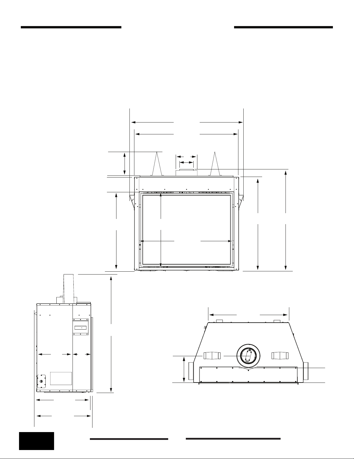
Fireplace Dimensions
The installation must conform with local codes or, in the absence of local codes, with the National
Fuel Gas Code, ANSI Z223.1/NFPA 54, or the National Gas and Propane Installation Code, CSA
B149.1
A manufactured home (USA only) or mobile home OEM installation must conform with the
Manufactured Home Construction and Safety Standard, Title 24 CFR, Part 3280, or, when such
a standard is not applicable, the Standard for Manufactured Home Installations, ANSI/NCSBCS
A225.1, or standard for Gas Equipped Recreational Vehicles and Mobile Housing , CSA Z240.4
41 3/4”
38 1/4”
8”
28 7/8”
8”
5”
34 1/4” 37 1/4”
27 7/8”
34 7/8”
Figure 1: Front view.
28 1/4”
22 3/4”
23 1/4”
100001042
42 3/8”
7”14”
9 3/8”
Figure 3: Top view.
Figure 2: Side view.
6
260619-56
z35
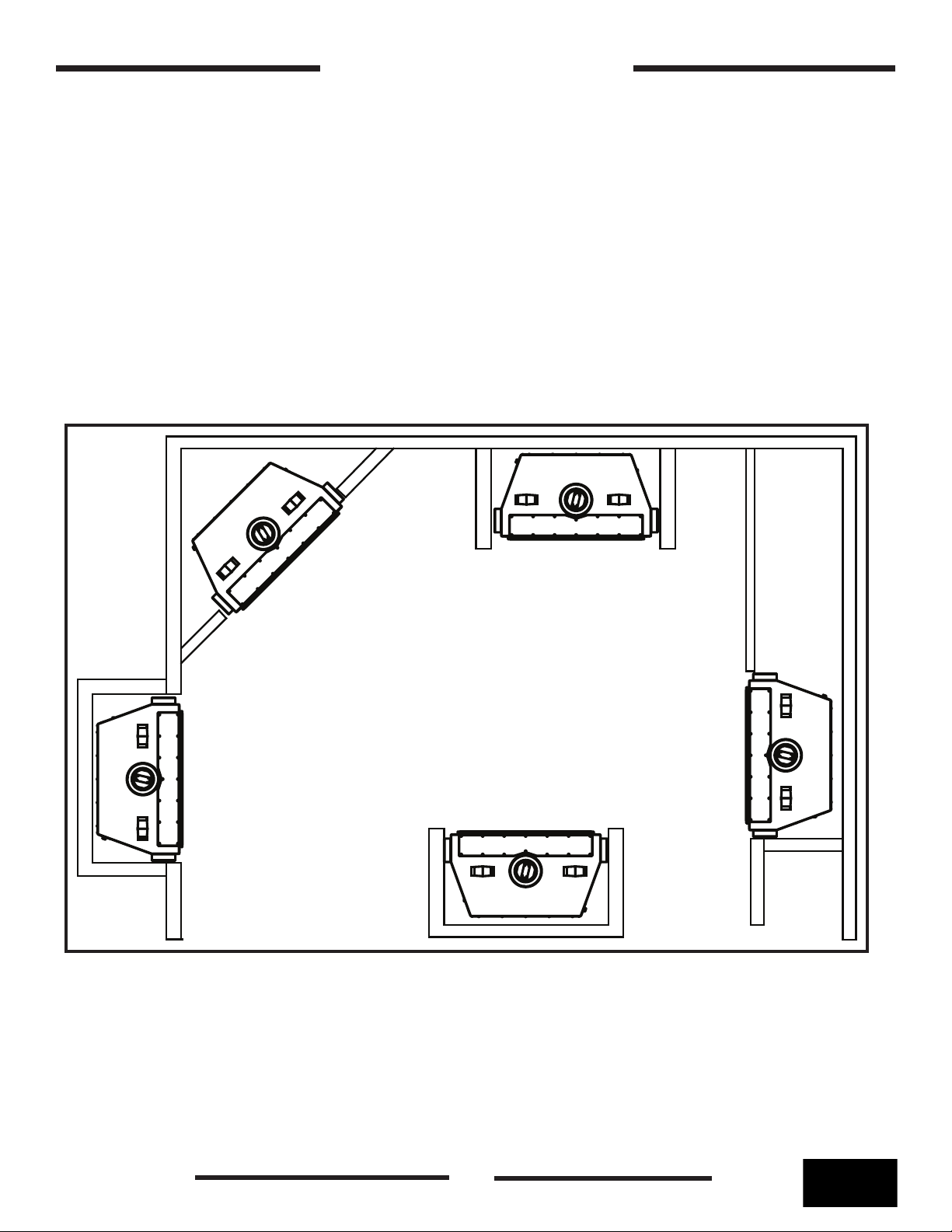
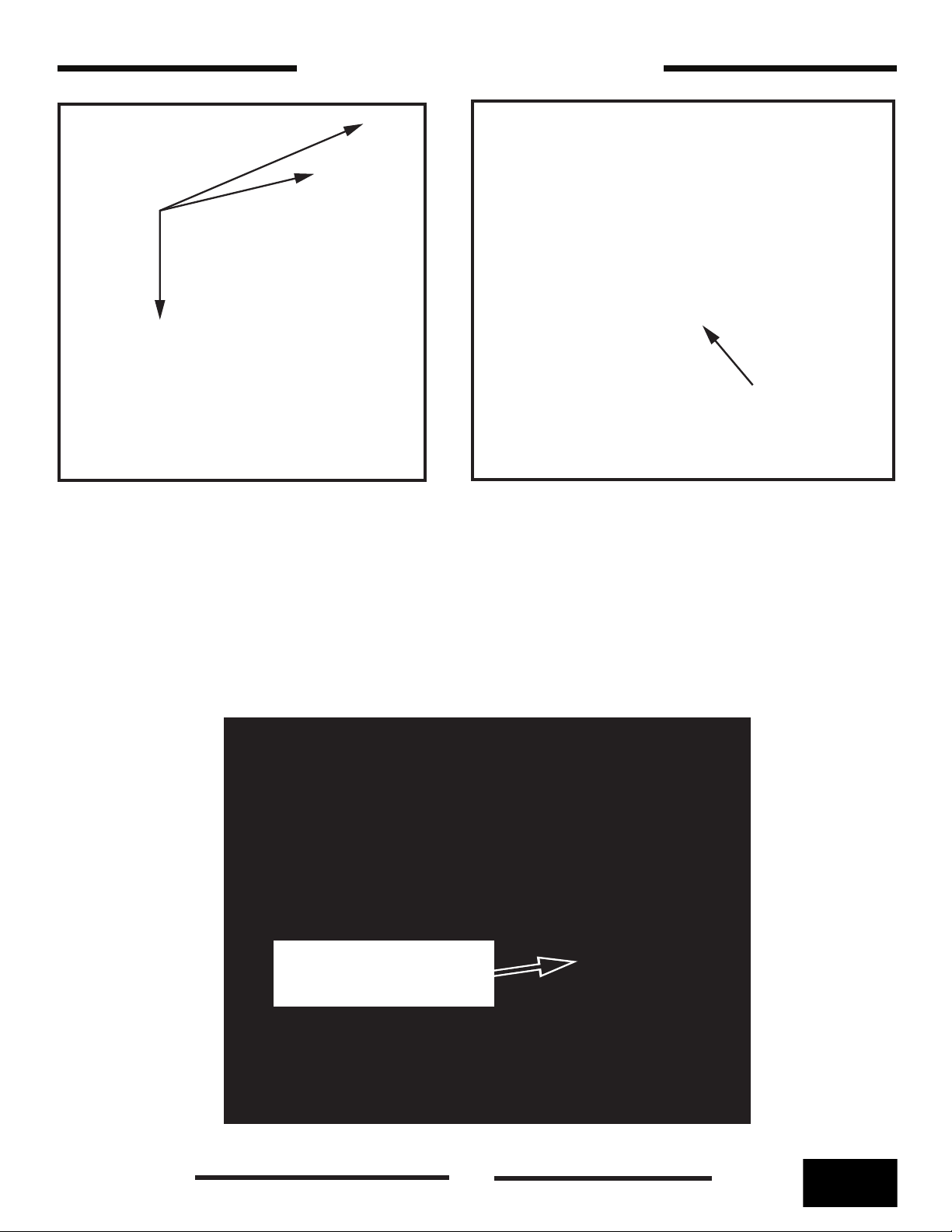
Locating the Fireplace
In planning the installation for the replace, it is necessary to determine where the unit is to
be installed, location of vent system and where gas supply piping may be plumbed. Various
installations are possible, such as, into an existing wall, a corner, a built in wall or a wall projection.
Due to high temperatures, do not locate this replace in areas of high trafc or near furniture or
draperies. For places where a second side wall is specied, replace should be accessible for
service
Front of the appliance is an open side of the combustion chamber covered with the glass.
Facing the front of the appliance side from left is the left side of the appliance and side from right is
the right side of the appliance.
Figure 4: Common installation examples.
z35
260619-56
7
100001042

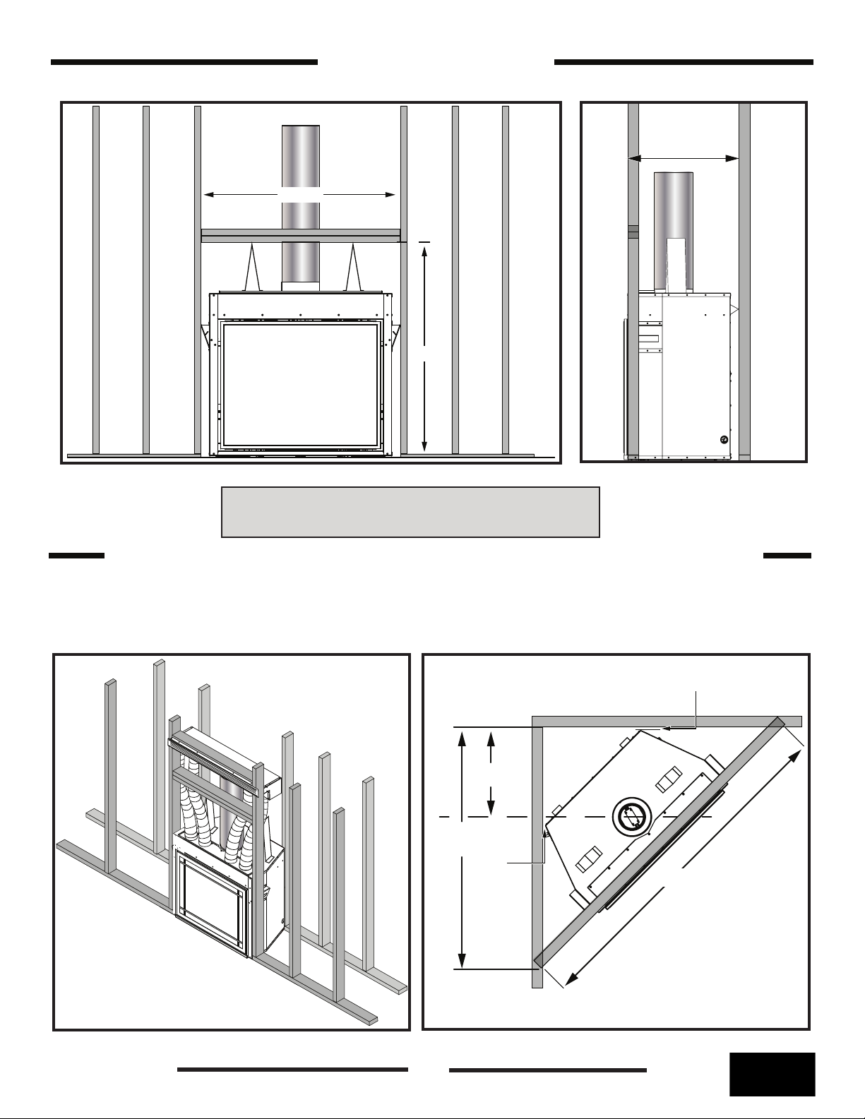
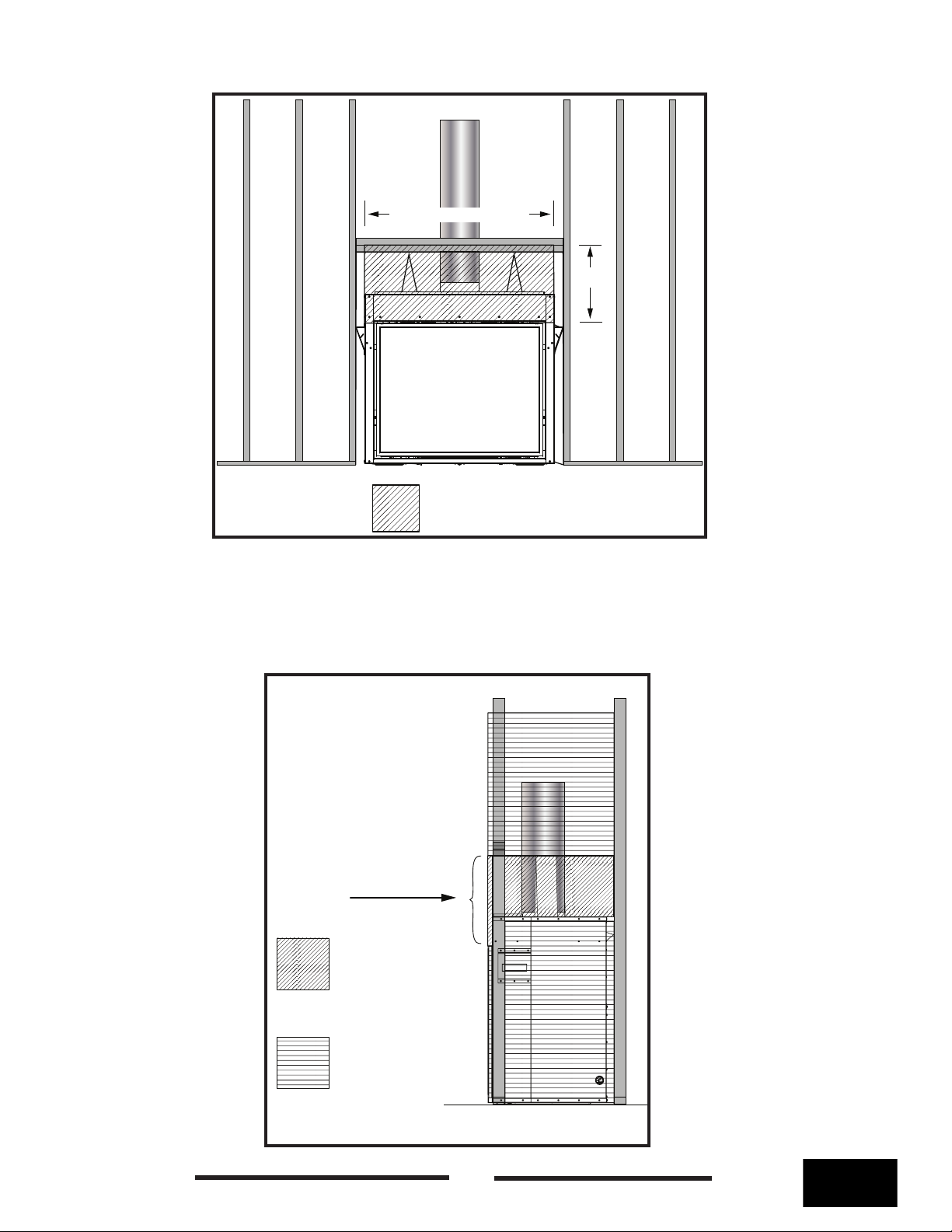
Framing and Finishing
Note: This replace should be in place and venting installed before framing in or building an
enclosure around the unit.
The z35 replace must be framed in as described below or totally enclosed with non-combustible
material, such as facing brick.
If preferred, additional masonry type non-combustible material can be installed above the appliance.
The finishing material must not interfere with glass door and safety screen removal.
The sides, back and top of the replace can be framed in using conventional lumber. Consult local
building codes for specic requirements.
Due to high temperatures, non-combustible material board, such as cement board or its equivalent,
must be used to sheet in above the replace, extending a minimum of 13” above the replace
opening so that the top of the non-combustible board is level with the top of the standoffs - (Figure
20 on page 15). Standard sheet rock (dry wall) may be used up to the sides of the replace
opening.
A header using two 2 x 4’s must be installed so that the bottom of the header is level with the top
standoffs (Figure 5). This header will support both combustible and non-combustible facing material
above the replace opening.
If backer board is not to be used, other non-combustible material such as tiles may be used. It
is recommended that top sections of the board be a single sheet of calcium silicate board or its
equivalent. Taped and mudded joints may crack due to the elevated temperatures.
Chase Insulation: When installing this replace against a non-insulated exterior wall or chase, it is
recommended that the outer walls be insulated to same degree as other exterior walls. Do not place
replace directly against the insulation. Cover the insulation and plastic vapour barrier with a solid
surface, such as dry wall (sheet rock). Consult local codes. Do not insulate between the top of the
replace and the top of the stand-offs.
100001042
8
260619-56
z35
23 1/4”
Framing in the z35
41 3/4”
42 3/8”
Figure 5: Framing front view.
Figure 6: Right side view.
Note: Position of bottom of the header should be
parallel with the top of the stand-offs (Figure 5).
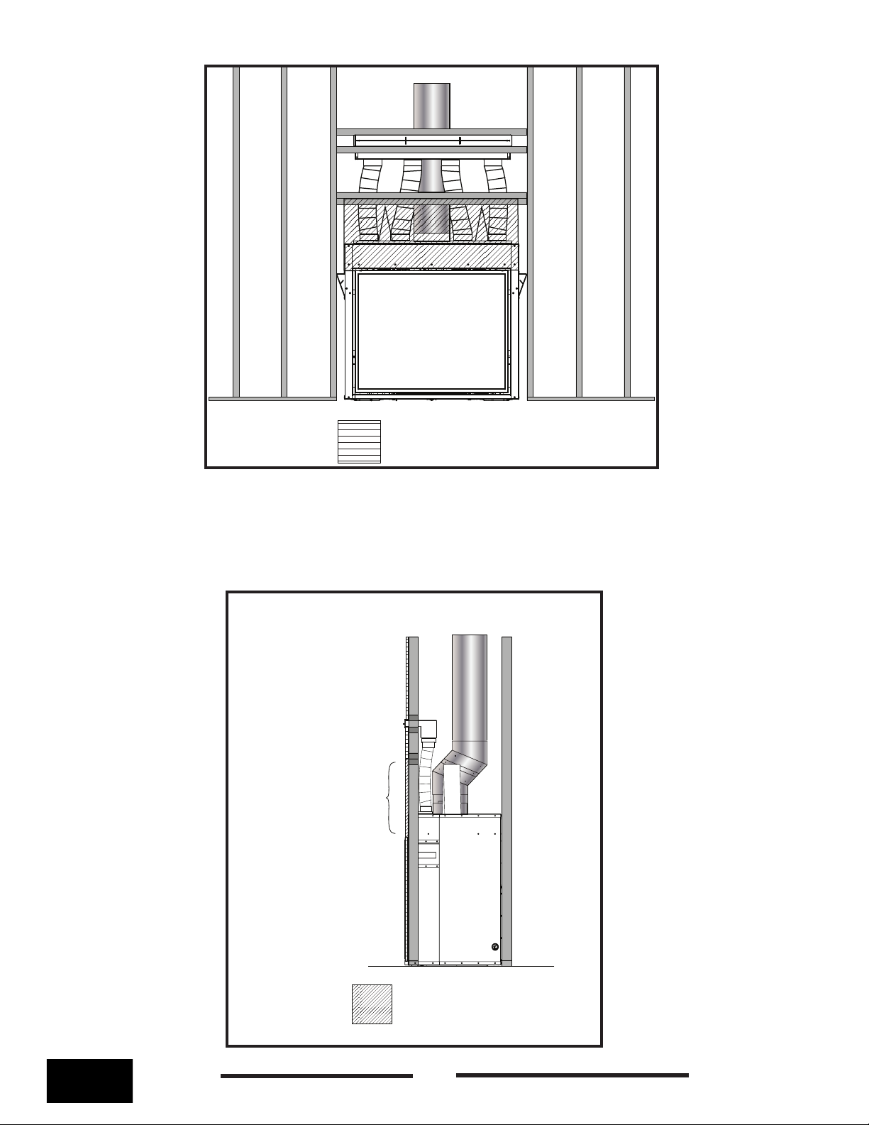
Framing in the z35 and Optional Cool Wall Venting Kit
For complete Cool Wall Venting installation instructions, see the installation manual which is
included with the Cool Air Venting Kit.
2”
20”
53 5/8”
2”
74 3/8”
Figure 7: Isometric framing.
z35
260619-56
Figure 8: z35 Corner Installation.
9
100001042
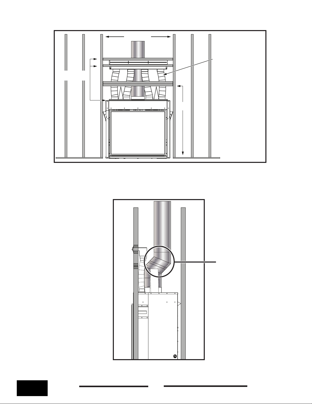
Note: Each of the exible
vent pipes come to the
customer site compressed
to 3 feet lengths and each
is expandable to 5 feet.
Therefore, the nal position
of the vent register must
take this range into
account when building
supports for the register.
42” Minumum
Vent register
distance is variable
42 3/8”
NOTE: If using the Cool Wall
Vent option, the cool wall vent
must be secured by headers
above and below the vent
(Figure 9).
Figure 9: Framing front view with cool wall kit.
Note: An offset will be
required when using
the Cool Wall Kit.
100001042
Figure 10: Side view of cool wall kit.
10
260619-56
z35
3 holes on top
of trim piece
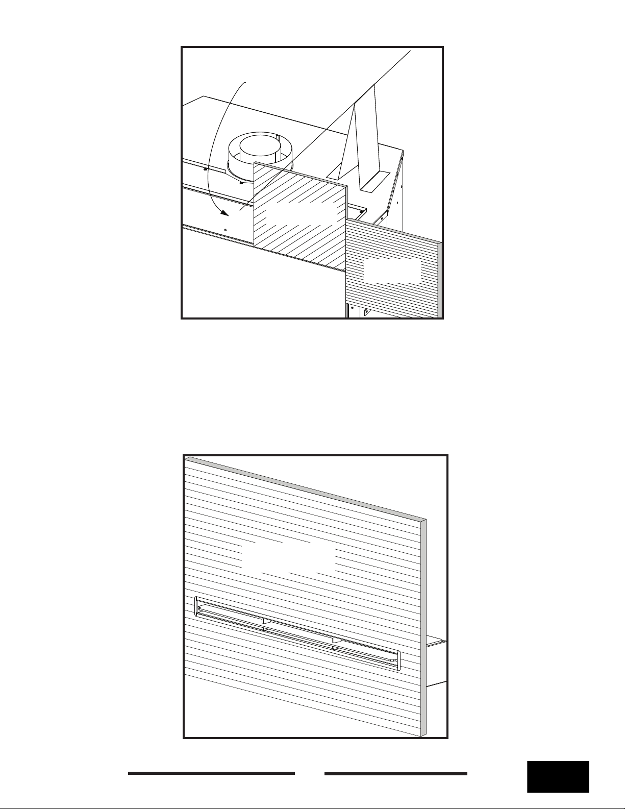
Lower Opening Trim Piece
Trim piece ts over the
lower lip.
Figure 11: Trim piece.
If this replace is installed directly on a oor as opposed to being installed in an elevated position, a
trim piece is provided to cover the space between the lower rebox lip and the oor. Be sure that the
3 holes (these are not screw holes) in the trim piece are facing up before installing (Figure 11). This
piece snaps on over the lower lip of the rebox (Figure 12). Make sure that the trim piece is rmly
seated on top of the lower rebox lip (Figure 13).
Figure 12: Firebox before trim piece in installed.
z35
260619-56
Trim piece ts onto
the lower lip
Figure 13: Trim piece seated on lower lip.
11
100001042
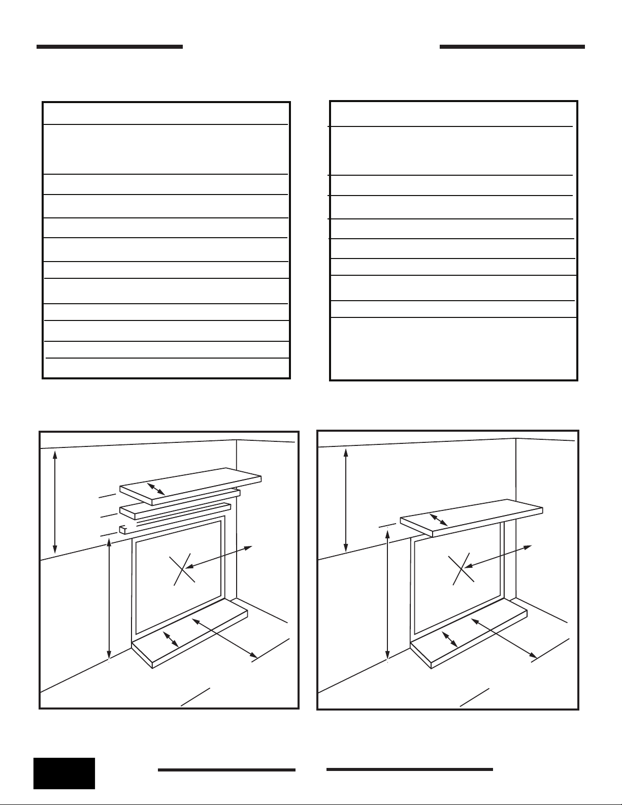
Clearances to Combustibles
Standard Configuration
Mantel Depth / Mantel Height (from floor)
1 “ / 36”
6” / 42”
9” / 48”
Hearth Clearance
0”
Objects in front of Appliance
36”
Under Appliance
0”
Clearance to exposed sidewall
20” from center of window
Ceiling to top of front surround
36” Minimum
Cool Wall Kit
Configuration
Mantel Depth / Mantel Height (from floor)
1 “ / 32”
6” / 32”
9” / 32”
Hearth Clearance
0”
Objects in front of Appliance
36”
Under Appliance
0”
Clearance to exposed sidewall
20” from center of window
Ceiling to top of front surround
36” Minimum
Ceiling
Standard Conguration
9”
48”
42”
36”
Top of front
surround
Figure 14: Standard clearances to combustibles.
6”
1”
20”
0”
Objects in front
of appliance 36”
Side
wall
Ceiling
Cool Wall Conguration
Mantel depth
range 1” to 9”
32”
20”
Top of front
surround
0”
Objects in front
of appliance 36”
Figure 15: Cool Wall clearances to combustibles.
Side
wall
100001042
12
260619-56
z35
Minimum width of the unit
14 1/2”
Non - combustible
materials zone
Figure 16: Combustible and non-combustible zones front view.
When framing and nishing in the z35, there are 2 zones that the installer must consider: combustible
materials zone and non-combustible materials zone. Building materials in the non-combustible
materials zone can utilize dry-wall or other combustible facing materials. Building materials in the non-
combustible zone must use non-combustible materials and insulation.
z35
260619-56
Non - combustible
material
Non combustible
materials zone
Combustible
materials
zone
13
Figure 17: Combustible and
non-combustible zones side
view.
100001042
Combustible
materials zone
Figure 18: Combustible and non-combustible side view with cool wall kit.
For installations using the optional cool wall kit, the combustible and non-combustible zones
remain the same as units not using the cool wall kit.
Non - combustible
material
100001042
Non - combustible
materials zone
14
Figure 19: Side view with
cool wall kit.
260619-56
z35
Facing material can be
afxed directly to the
front wall above the
glass door.
Non-combustible
material
Facing material can be
installed up to and
against the outside edge
of the replace opening.
Figure 20: Combustible and non combustible zones details.
Combustible
material
Combustible facing material may be butted up to, and against the side edges of the replace
opening except for the area directly above the replace opening (Figure 20). Only non-combustible
material may be used in this area.
Combustible facing material may be used to nish the Cool Wall Kit (Figure 21) as long as the
material does not encroach on the non-combustible zone. (Figure 16).
Combustible
material
z35
260619-56
Figure 21: Cool wall vent and facing material.
15
100001042

36’
35’
34’
33’
32’
31’
30’
29’
28’
27’
26’
25’
24’
23’
22’
21’
20’
19’
18’
17’
16’
15’
14’
13’
12’
11’
10’
9’
8’
7’
6’
5’
4’
3’
2’
1’
0’
Venting Chart
No venting options
Venting envelope
Venting envelope
No venting options
1’ 2’ 3’ 4’ 5’ 6’ 7’ 8’ 9’ 10’ 11’ 12’ 13’ 14’ 15’ 16’
0’
17’
19’ 20’ 21’
18’
^ a vent shall not terminate directly above a side-walk or paved driveway which is located between two single family dwellings and serves both dwellings*
** only permitted if veranda, porch, deck, or balcony is fully open on a minimum of 2 sides beneath the oor*
* as specied in CGA B149 Installation Codes, Note: local Codes or Regulation may require different clearances
* for U.S.A. Installations follow the current National Fuel Gas Code, ANSI Z223.1
Note: The vent must not exceed a total length of 35 feet. Any combination of rise and run may be
used but must be constrained to the boundaries of this chart. A Maximum of three 90° elbows may
be used. Only one (1) 90° elbow or combination of other elbows equaling 90° can be used without
reducing horizontal run. For each additional 90° elbow, or an equal combination of elbows, reduce
horizontal vent run by 2 feet. Ensure vent pipe is properly supported.
100001042
16
260619-56
z35
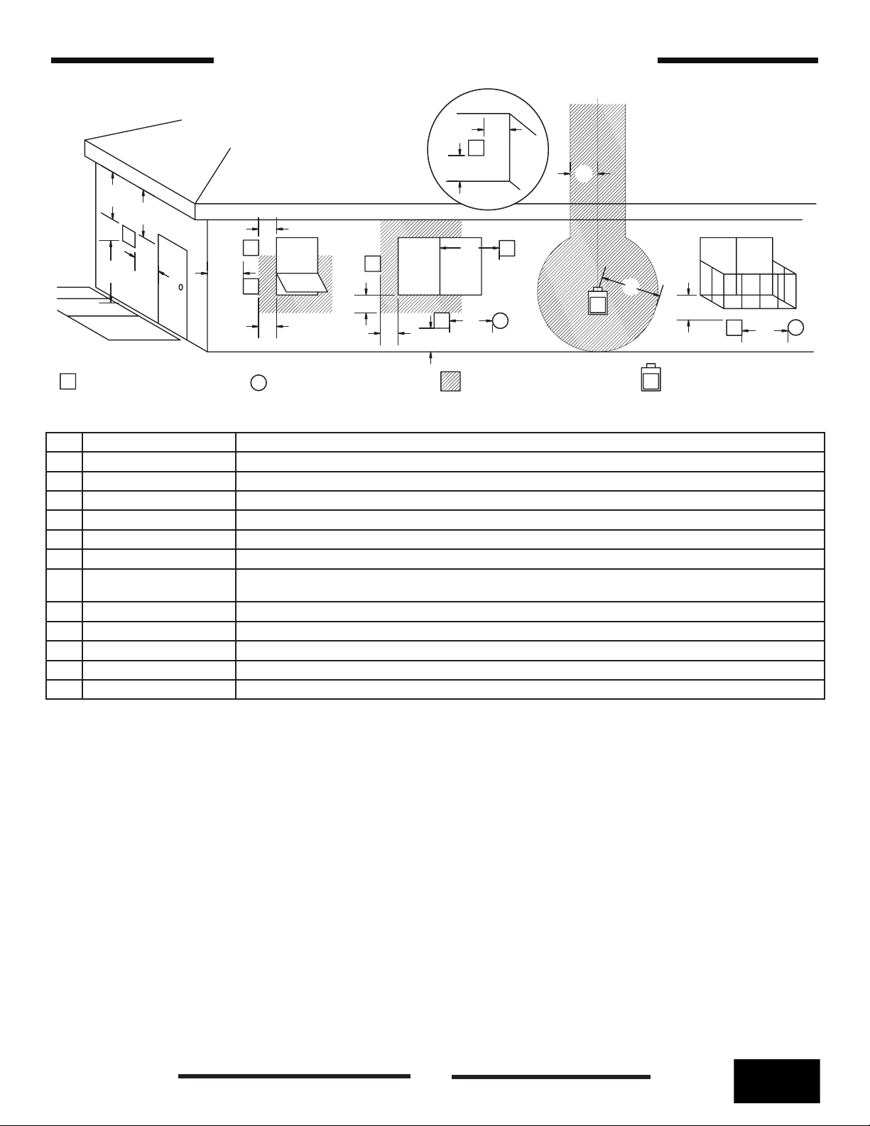
Vent Terminal Minimum Clearances
G
V
A
D
E
V
B
L
C
FIXED
V
CLOSED
F
OPEN-
ABLE
V
B
B
OPEN-
V
ABLE
B
V
A
B
FIXED
CLOSED
J
V
A
H
I
G
M
V
A
K
VENT TERMINAL
V
A= *12 inches (30 cm) min. Clearances above grass, top of plants, wood, combustible veranda, porch, deck, or balcony.
B= *12 inches (30 cm) min. Clearance beside or below a window or door that may be opened.
C= 12 inches (30 cm) min. Clearance to permanently closed window recommended to prevent condensation on window.
D= 16 inches (40 cm) min. Vertical clearance to ventilated soft located above the terminal within a horizontal distance of 16 inches (40 cm) .
E= 16 inches (40 cm) min. Clearance to unventilated soft.
F= 6 inches (15 cm) min. Clearance to outside corner.
G= 6 inches (15 cm) min. Clearance to inside corner.
H= 3 feet (90 cm) min. *Not to be installed above a meter/regulator assembly within 3feet (90 cm) horizontally from the center-line of
I= *6 feet (1.8 m) min. Clearance to service regulator vent outlet.
J= *12 inches (30 cm) min. Clearance to non mechanical air supply inlet to building or the combustion air inlet to any other appliance.
K= *6 feet (1.8 m) min. Clearance to a mechanical air supply inlet.
L= *7 feet (2.1 m) min. ^ Clearance above paved side-walk or a paved driveway located on public property
M= **16 inches (40 cm) min. Clearance under veranda, porch, deck, or balcony
AIR SUPPLY INLET
A
the regulator.
AREA WHERE TERMINAL
IS NOT PERMITTED
GAS METER
G
This replace is certied for use with 5” x 8”coaxial venting components only. It is permitted
to only use certied venting for this appliance.
z35
260619-56
17
100001042
 Loading...