

Pacific energy VISTA D Installation And Operating Instructions Manual
IMPORTANT:
THESE INSTRUCTIONS ARE TO
REMAIN WITH THE HOMEOWNER
SAFETY NOTICE
If this stove is not properly installed, a house
re may result. For your safety, follow the
installation instructions. Contact local
building or re officials about restrictions
and installation inspection requirements in
you area.
SERIAL #
INSTALLATION
AND OPERATING
INSTRUCTIONS
TESTED and LISTED to CAN/ULC S627
and UL 1482
Meets the Environmental Protection
Agency’s May 2015 Particulate
Emission Standards
200516-20 VISTA INSERT-D 5055.3231
Model:
PACIFIC VISTA INSERT
Series: D

Contents
Safety ............................................................................................ 3
Dimensions ............................................................................................ 3
Clearances ................................................................................... 3
Masonry or Factory Built Fireplace ........................................................ 3
Maintenance Checks ................................................................... 4
Installation .................................................................................... 6
Fireplace Speci cations ......................................................................... 6
Into a Masonry Fireplace ....................................................................... 6
Full Flue Liner -(Required in Canada) .................................................... 7
Direct Flue Connection - (USA only) ..................................................... 7
Into a Factory Built Fireplace ................................................................. 7
Surround Assembly and Installation ...................................................... 8
Combustion Air ...................................................................................... 9
Blower ........................................................................................... 9
Blower Operation ................................................................................... 9
Electrical Supply .................................................................................... 9
Operation .................................................................................... 10
Wood Selection.....................................................................................10
How to Test Your Wood .........................................................................10
Lighting a Fire .......................................................................................10
Normal Operation .................................................................................10
Restarting After Extended Burns ..........................................................10
Over Firing ............................................................................................ 11
Heat Output Calculation .......................................................................11
Proper Draft ..........................................................................................11
Ash Removal ........................................................................................11
Disposal of Ashes ................................................................................. 11
Chimney Smoke and Creosote Formation ............................................ 11
Chimney Fires ....................................................................................... 11
In Case of a Chimney Fire ....................................................................11
Avoiding a Chimney Fire .......................................................................12
Maintenance ............................................................................... 12
Blower Maintenance .............................................................................12
Baffle Removal ......................................................................................12
Appendix A ................................................................................. 13
Troubleshooting ....................................................................................13
Firebrick Installation Instructions ..........................................................14
Replacement Parts ...............................................................................15
Replacement Parts - Blower .................................................................16
Optional Hearth Trim Kit .......................................................................17
Warranty Information ................................................................. 18
Label .....................................................................................................19
PLEASE SAVE THESE INSTRUCTIONS
This manual describes the installation and operation of the Paci c Energy, VISTA INSERT wood heater. This heater
meets the 2015 U.S. Environmental Protection Agency's crib wood emission limits for wood heaters sold after May
15, 2015. Under speci c test conditions this heater has been shown to deliver heat at rates ranging from 12,400 to
26,300 Btu/hr.
NOTE: WE STRONGLY RECOMMEND THAT SMOKE AND CARBON MONOXIDE DETECTORS BE INSTALLED IN THE
AREA WHERE THE HEATER IS TO BE INSTALLED.
If smoke detectors have been previously installed, you may notice that they are operating more frequently. This may be due
to curing of stove paint or fumes caused by accidentally leaving the re door open. Do not disconnect the detectors.
SAFETY NOTICE: If this stove is not properly installed, a house re may result. For your safety, follow the installation instructions. Contact local building or re officials about restrictions and installation inspection requirements
in you area.
Please read this entire manual before you install and use your new room heater. Failure to follow instructions may result in
property damage, bodily injury, or even death.
2 VISTA INSERT-D 200516-20
Safety
Clearances
READ ALL INSTRUCTIONS BEFORE INSTALLING
AND USING THIS APPLIANCE. FAILURE TO FOLLOW
INSTRUCTIONS MAY RESULT IN PROPERTY DAMAGE,
BODILY INJURY, OR EVEN DEATH.
We strongly recommend that smoke detectors be installed.
If smoke detectors have been previously installed, you may
notice that they are operating more frequently. This may be
due to curing of stove paint or fumes caused by accidentally
If necessary, relocate them to reduce their sensitivity.
SAFETY NOTICE: If this stove is not properly installed, a
tions and installation inspection requirements in your area.
ed by the Wood
Energy Technical program (WETT) - in Canada, Hearth
Education Foundation (HEARTH) - in U.S.A. (or equivalent)
are strongly recommended.
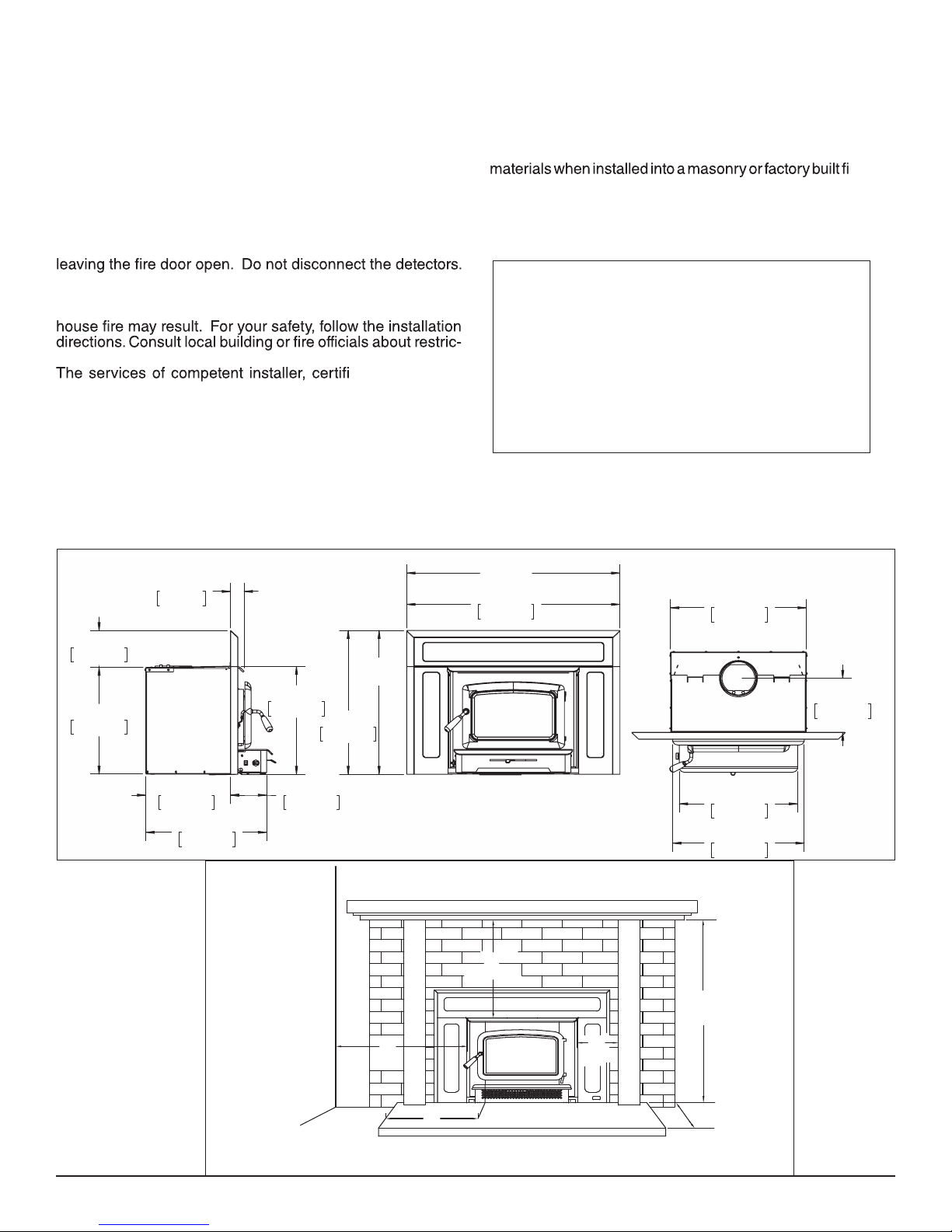
Dimensions
2 3/8"
59mm
6 5/8"
170mm
19 3/4"
501mm
*30"
19 1/2"
495mm
661mm
[762mm]
26"
Masonry or Factory Built Fireplace
The minimum required clearances to surrounding combustible
replace
are listed below and in Fig. #1.
Minimum Clearances to Combustibles
(Measured From Insert Body)
Adjacent Sidewall ........................... 9 in. (229 mm.)
Mantel ........................................... 15 in. (381 mm.)
Top Facing .............................. 15 in. (381 mm.)
Side Facing ............................... 9 in. (229 mm.)
*42"
[1.07m]
36 1/2"
927mm
23 1/4"
591mm
9 3/4"
249mm
14 1/2"
368mm
20 5/8"
525mm
Fig. # 1
6 1/8"
157mm
Adjacent
Wall
200516-20 VISTA INSERT-D 3
*Oversized Surround
Mantel or Top Facing
381mm
9”
229mm
8”
203mm
15”
Hearth
9”
229mm
Side Facing
34 3/4”
883mm
16”
406mm
20 1/4"
514mm
22 1/2"
571mm

Maintenance Checks
Check the following parts for damage such as cracks, excessive corrosion, burned out sections and
excessive warping: (See website for descriptions and more detail)
Weekly:
- Firebrick - Visual, for cracking.
- Door Gasket - sagging, placement, damage.
Monthly
- Brick rail tabs and brick rails.
- Air riser tube in the back of the rebox.
- Back side of airwash chamber.
- Baffle locking pin.
- Boost tube cover.
When Cleaning the
Chimney System:
- Top baffle board/blanket.
- Baffle.
- Top heat shield and mounting bolt.
- Baffle Gasket.
- Brick Rails.
- Manifold.
Blower:
- The blower should be cleaned out a minimum every six months by using a vacumn on the blower
intake openings to remove any dust and debris.
Baffle:
- Some warping of the baffle is normal(up to 1/4” or .65cm).
- Replace if the baffle has permanent warping greater than this or has cracking or breakage.
- Please contact your Dealer if you experience any of the damage listed above. Continuing to operate
your stove with broken parts may accelerate damage to other parts and may void your warranty
4 VISTA INSERT-D 200516-20
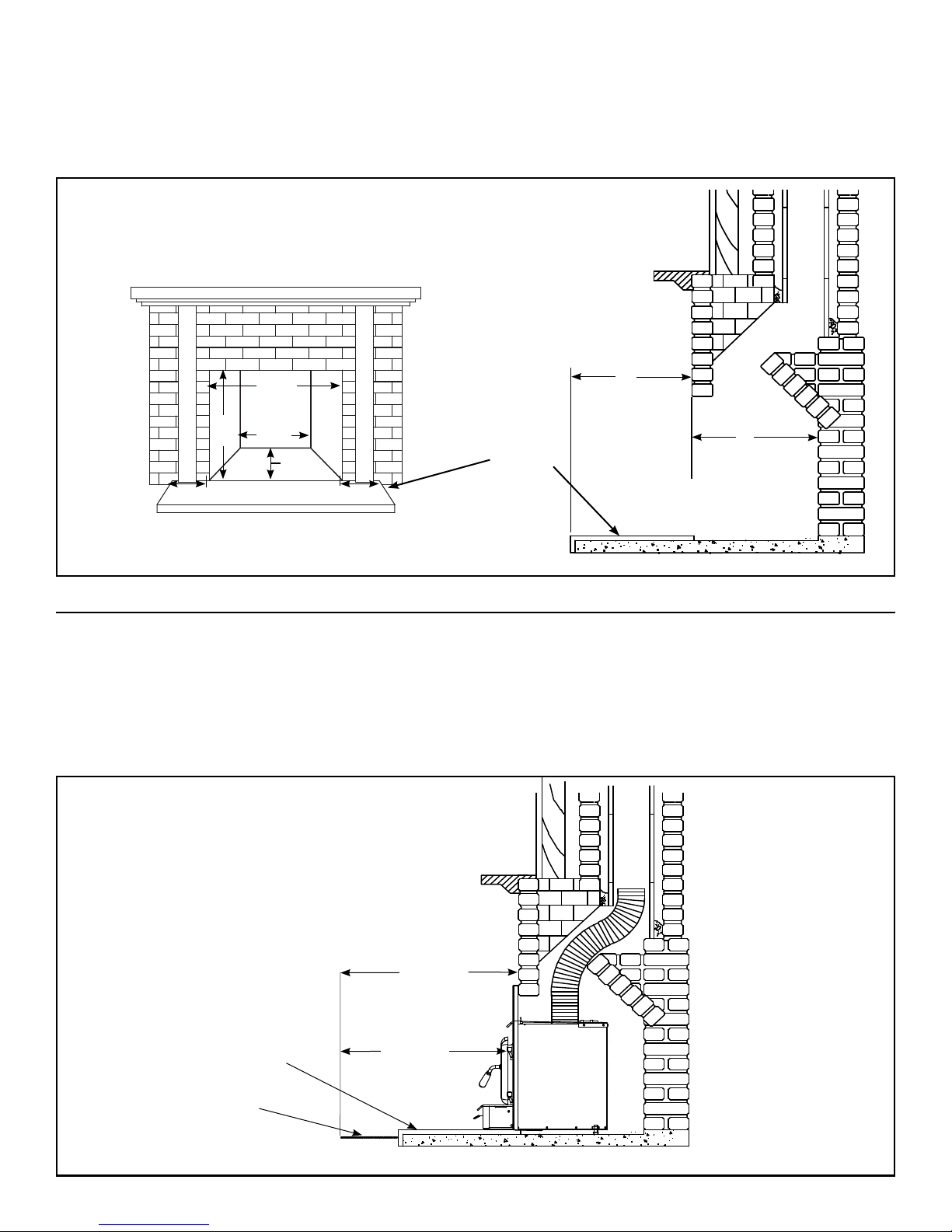
Fireplace hearth requirements: (Measured without the insert)
The hearth may be ush with or raised above an adjacent combustible oor and must extend 16”(406mm) in front and
*
8”(203mm) beyond each side of the replace opening.
MINIMUM FIREPLACE
OPENING AND HEARTH
DIMENSIONS
24”
610mm
20”
508mm
8”
203mm
Ember protection:
Combustible oor in front of the replace insert must be protected from hot embers by non-combustible material ex-
**
tending 16”(406mm) (USA) and 18”(457mm) (CANADA) to the ring side and 8”(203mm) to other sides of the unit.
Consult CAN/CSA-B365 Installation Code for Solid-Fuel-Burning appliances and equipment in Canada, and N.F.P.A.
211 Standard for chimneys, replaces, vents and Solid-Fuel-Burning appliances in USA.
24”
610mm
15”
381mm
Non-combustible replace
hearth
8”
203mm
16”
406mm
15”
381mm
MINIMUM EMBER
PROTECTION
DIMENSIONS
Non-combustible hearth
Non-combustible oor
covering
200516-20 VISTA INSERT-D 5
18”(457mm) USA
20”(508mm) CANADA
16”(406mm) USA
**
18”(457mm) CANADA
Installation
Your Insert is designed to be installed into a masonry or factory built zero-clearance replace. The masonry replace
must be built according to the requirements of the Standard
of Chimneys, Fireplaces, Vents and Solid Fuel Burning
appliances, N.F.P.A. 211 (Latest Edition) or applicable Na-
tional, Provincial, State or local codes. The installation shall
conform to CAN/CSA-B365, Installation Code for Solid-
Fuel-Burning Appliances and Equipment. The factory
built zero-clearance replace and its chimney must be listed
per UL 127 or ULC S610 standards.
Warning: Under no circumstances is this heater to be installed
in a makeshift or "temporary" manner.
DO NOT CONNECT THIS UNIT TO A CHIMNEY FLUE
SERVICING ANOTHER APPLIANCE.
Fireplace Speci cations
Your replace is required to have the following minimum sizes:
WIDTH 23-1/2" (597 mm)
HEIGHT 19-7/8" (505 mm)
DEPTH 15" (381 mm)
Chimney height 15'(4.5m) (minimum).
A metal tag is provided and is to be fastened to the back
wall of the replace, if the replace has been modi ed
to accommodate the insert.
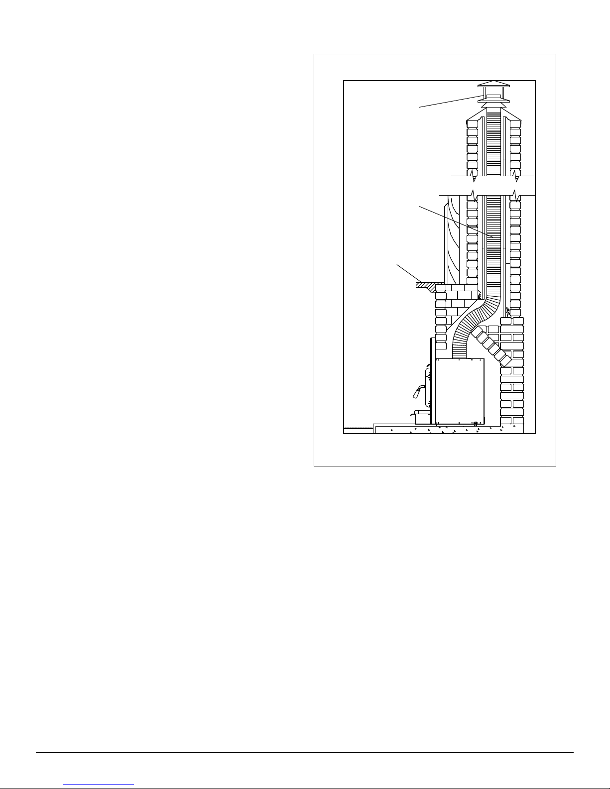
Fig. # 4
Full Flue Liner
Rain Cap
6”(150mm) Stainless
Steel Rigid or Flex
Liner
Mantel or
Top Facing
Into a Masonry Fireplace
Inspect your replace for cracks, loose mortar or other physical defects. If repairs are required, they should be completed
before installing your insert.
The replace chimney must be suitable for wood burning use.
Check for creosote build up or other obstructions, especially
if it has not been in use for some time.
The existing replace damper is to be locked open or removed
completely.
WARNING: Do not remove bricks or mortar from your
existing replace.
Exception: Masonry or steel, including the damper plate,
may be removed from the smoke shelf and adjacent damper
frame if necessary to accommodate a chimney liner, provided
that their removal will not weaken the structure of the replace
and chimney, and will not reduce protection for combustible
materials to less than that required by the National Building
Code.
The Insert must be installed in accordance with local and or
national building codes. The two methods of ue connection
that are acceptable in most areas are:
Full Flue Liner: where a listed stainless steel rigid or exible
liner extends from the Inser t ue collar to the top of the chimney.
Direct Flue Connection: where a listed stainless steel rigid
or exible liner extends from the Insert ue collar to the rst
chimney ue liner.
Note: A clean-out door may be required under local codes,
when a direct ue connection is used. Consult local codes.
Paci c Energy highly recommends the use of a full liner
as the safest installation and providing optimum performance. When connected to a full liner, the Insert is able
to draft correctly and will prevent problems such as dif cult start-ups and smoking out the door.
6 VISTA INSERT-D 200516-20
 Loading...