

Pacific energy TOFINO i30s, TOFINO i30m, TOFINO i20s, TOFINO i20m, TOFINO i20 Installation Instructions Manual
INSTALLATION INSTRUCTIONS
INSTALLER:
Leave this manual with the appliance.
CONSUMER:
Retain this manual for future reference.
WARNING: If the information in these
instructions is not followed exactly a fire
or explosion may result causing property
damage, personal injury or death.
FOR YOUR SAFETY
Do not store or use gasoline or other flammable
vapours and liquids in the vicinity of this or any
other appliance.
WHAT TO DO IF YOU SMELL GAS
tDo not try to light any appliance.
tDo not touch any electrical Switch.
tDo not use any phone in your building.
tImmediately call your gas supplier from a
neighbour’s phone. Follow the gas supplier’s
instructions.
tIf you cannot reach your gas supplier call the
fire department.
Installation and service must be performed by
a qualified installer, service agency or the gas
supplier.
TOFINO
INSTALLATION
INSTRUCTIONS
This appliance may be installed in an after-
market permanently located, manufactured
home (USA only) or mobile home, where not
prohibited by local codes.
This appliance is only for use with the type of
gas indicated on the rating plate. This appliance
is not convertible for use with other gases
unless a certified kit is used.
This appliance is suitable for installation in a
bedroom or bed sitting room.
Visit www.pacificenergy.net for the most recent version of this manual
130717-44
TOFINO
MODEL: TOFINO i30s
TOFINO i30m
(SIT & Maxitrol versions)
SERIES: A
DIRECT VENT GAS INSERT
5055.990-A

Table Of Contents
Important Note for the Commonwealth of Massachusetts ....... 3
Caution ...................................................................................... 4
Safety ........................................................................................ 5
WHAT TO DO IF YOU SMELL GAS ................................... 5
First Fire ..................................................................................... 6
Warnings and Cautions ............................................................. 6
Fireplace Dimensions .................................................................7
Tofino Insert Backing Plate Dimensions .................................... 8
Existing Fireplace Preparation ................................................... 9
Clearances to Combustibles ................................................... 10
Horizontal Clearances ...................................................... 10
Objects in front of Appliance ........................................... 10
Mantel Clearances ........................................................... 10
Mantel Depth ................................................................... 10
Hearth Clearance ............................................................. 10
Under Appliance .............................................................. 10
Adjustable Leveling Bolts .........................................................11
Removable Handles .................................................................11
Venting ..................................................................................... 12
Installation Advisory ......................................................... 12
Installation Tip .................................................................. 12
Optional 4” to 3” exhaust adapter ................................... 12
SIT Control Overview ............................................................... 14
Maxitrol Control Overview ....................................................... 14
Door Installation/Removal ....................................................... 15
Removal ........................................................................... 15
Installation ........................................................................ 15
Panel Installation ..................................................................... 16
Installation .........................................................................17
Baffle ....................................................................................... 18
Cleaning the ceramic glass baffle: ................................... 18
Installing the ceramic baffle: ............................................ 18
Electrical Supply ...................................................................... 19
Gas Supply .............................................................................. 19
Gas Valve for SIT Configuration .............................................. 20
SIT controller .................................................................... 20
SIT gas valve .................................................................... 20
Gas valve for Maxitrol Configuration ........................................21
Maxitrol controller .............................................................21
Maxitrol gas valve .............................................................21
Gas Pressure Check / Output / Efficiency ................................ 22
Gas Pressure Testing Procedure ............................................. 23
Damper Adjustment ................................................................ 24
Damper Adjustment ......................................................... 24
Venturi Adjustment .................................................................. 25
Glass Media Installation .......................................................... 26
Split Log Set Installation ...........................................................27
Log set Installation ........................................................... 28
Manual Switch Installation for SIT Units .................................. 33
To install ON/OFF Switch ................................................. 33
Manual Switch Installation for Maxitrol Units .......................... 35
To install ON/OFF Switch ................................................. 35
Surround Installation/Removal Instructions .............................37
Installation .........................................................................37
Removal ............................................................................37
Lighting Instructions ................................................................ 38
Maintenance ............................................................................ 39
Glass Door: ...................................................................... 39
Periodically: ...................................................................... 39
Wiring Diagram for SIT Proflame ............................................. 40
Wiring Diagram for Maxitrol ......................................................41
Tofino i30 Rating Label ............................................................ 42
2
130717-44
5055.990-Ai30 TOFINO

Important Note for the Commonwealth of Massachusetts:
From Massachusetts Rules and Regulations 248 5.08:
(a) For all side wall horizontally vented gas fueled equipment installed in every dwelling, building or structure used in whole or
in part for residential purposes, including those owned or operated by the Commonwealth and where the side wall exhaust
vent termination is less than seven (7) feet above finished grade in the area of the venting, including but not limited to decks
and porches, the following requirements shall be satisfied.
1. INSTALLATION OF CARBON MONOXIDE DETECTORS. At the time of installation of the side wall horizontal vented gas
fueled equipment,the installing plumber or gas fitter shall observe that a hard wired carbon monoxide detector with an alarm
and battery back-up is installed on the floor level where the gas equipment is to be installed, in addition, the installing
plumber or gas fitter shall observe that a battery operated or hard-wired carbon monoxide detector with an alarm is installed
on each additional level of the dwelling, building or structure served by the side wall horizontal vented gas fueled equipment.
It shall be the responsibility of the property owner to secure the services of qualified licensed professionals for the installation
of hard-wired carbon monoxide detectors.
a. In the event that the side wall horizontally vented gas fueled equipment is installed in a crawl space or an attic, the hard-
wired carbon monoxide detector with alarm and battery back-up may be installed on the next adjacent floor level.
b. In the event that the requirements of this subdivision cannot be met at the time of completion of installation, the owner shall
have a period of thirty (30) days to comply with the above requirements; provided, however, that during said thirty (30) day
period, a battery operated carbon monoxide detector with an alarm shall be installed.
2. APPROVED CARBON MONOXIDE DETECTORS. Each carbon monoxide detector as required in accordance with the above
provisions shall comply with NFPA 720 and be ANSI/UL 2034 listed as IAS certified.
3. SIGNAGE. A metal or plastic identification plate shall be permanently mounted to the exterior of the building at a minimum
height of eight (8) feet above grade directly in line with the exhaust vent terminal for the horizontally vented gas fueled
heating appliance or equipment. The sign shall read, in print size no less than one-half (1/2) inch in size, “GAS VENT
DIRECTLY BELOW. KEEP CLEAR OF ALL OBSTRUCTIONS”.
4. INSPECTION. The state or local gas inspector of the side wall horizontally vented gas fueled equipment shall not approve
the installation unless, upon inspection, the inspector observes carbon monoxide detectors and signage installed in accor
dance with the provisions of 248 CMR 5.089(2) (a) 1 through 4.
(b) EXEMPTIONS. The following equipment is exempt from 248 CMR 5.089(2)(a) 1 through 4.
1. The equipment listed in Chapter 10 entitled “Equipment Not Required To Be Vented” in the most current edition of NFPA 54
as adopted by the Board; and
2. Product Approved side wall horizontal vented gas fueled equipment installed in a room or structure separate from the
dwelling, building or structure used in whole or in part for residential purposes.
(c) MANUFACTURER REQUIREMENTS – GAS EQUIPMENT VENTING SYSTEM PROVIDED. When the manufacturer of Product
Approved side wall horizontally vented gas equipment provides a venting system design or venting system components with
the equipment, the instructions provided by the manufacturer for installation of the equipment and the venting system shall
include:
1. Detailed instructions for the installation of the venting system design or the venting system components; and
2. A complete parts list for the venting system design or venting system.
(d) MANUFACTURER REQUIREMENTS – GAS EQUIPMENT VENTING SYSTEM NOT PROVIDED. When the manufacturer of a
Product Approved side wall horizontally vented gas fueled equipment does not provide the parts for venting the fuel
gases, but identifies “special venting systems”, the following requirements shall be satisfied by the manufacturer.
1. The referenced “special venting system” instructions shall be included with the appliance or equipment installation
instructions; and
2. The “special venting systems” shall be Product Approved by the Board, and the instructions for that system shall include a
parts list and detailed installation instructions.
(e) A copy of all installation instructions for all Product Approved side wall horizontally vented gas fueled equipment, all venting
instructions, all parts lists for venting instructions, and/or all venting design instructions shall remain with the appliance or
equipment at the completion of the installation.
5055.990-A
130717-44
3
i30 TOFINO
Caution
FOR YOUR SAFETY - Do not install or operate your Pacific Energy fireplace without first reading
and understanding this manual. Any installation or operational deviation from the following instructions voids the Pacific Energy Fireplace Warranty and may prove hazardous.
This appliance and its individual shut off valve must be disconnected from gas supply piping system
during any pressure testing of that system at test pressures in excess of 1/2 psig (3.5 kPa).
This appliance must be isolated from the gas supply piping system by closing its individual manual
shut off valve during any pressure testing of the gas supply piping system at test pressures equal to
or less than 1/2 psig (3.5 kPa).
Note: When lit for the first time, the appliance will emit a slight odour for a couple of hours. This
is due to the curing of paints, sealants and lubricants used in the manufacturing process. This
condition is temporary. Open doors and windows to ventilate area. Smoke and fumes caused by the
curing process may cause discomfort to some individuals.
Do not use the fireplace if any part has been under water. Immediately call a qualified service
technician to inspect the fireplace and to replace any part of the control system and any gas control
which has been under water.
7KLV¿UHSODFHLVHTXLSSHGZLWKDPLFURPHVKVDIHW\VFUHHQIRU\RXUSURWHFWLRQDQG
PXVWEHLQVWDOOHGZLWKWKHXQLW5HPRYDORIWKHVDIHW\VFUHHQZLOOFDXVHWKH¿UHSODFH
WREHFRPHDEXUQKD]DUG
4
130717-44
5055.990-Ai30 TOFINO

Safety
rDue to high temperatures, this gas appliance should be located out of traffic and away from
furniture and draperies.
rChildren and adults should be alerted to the hazards of high surface temperatures and should
stay away to avoid burns or clothing ignition.
rYoung children should be carefully supervised when they are in the same room as the appliance.
Toddlers, young children and others may be susceptible to accidental contact burns. A physical
barrier is recommended if there are at risk individuals in the house. To restrict access to a
fireplace or stove, install an adjustable safety gate to keep toddlers, young children and other at
risk individuals out of the room and away from hot surfaces.
rClothing or other flammable material should not be placed on or near the appliance.
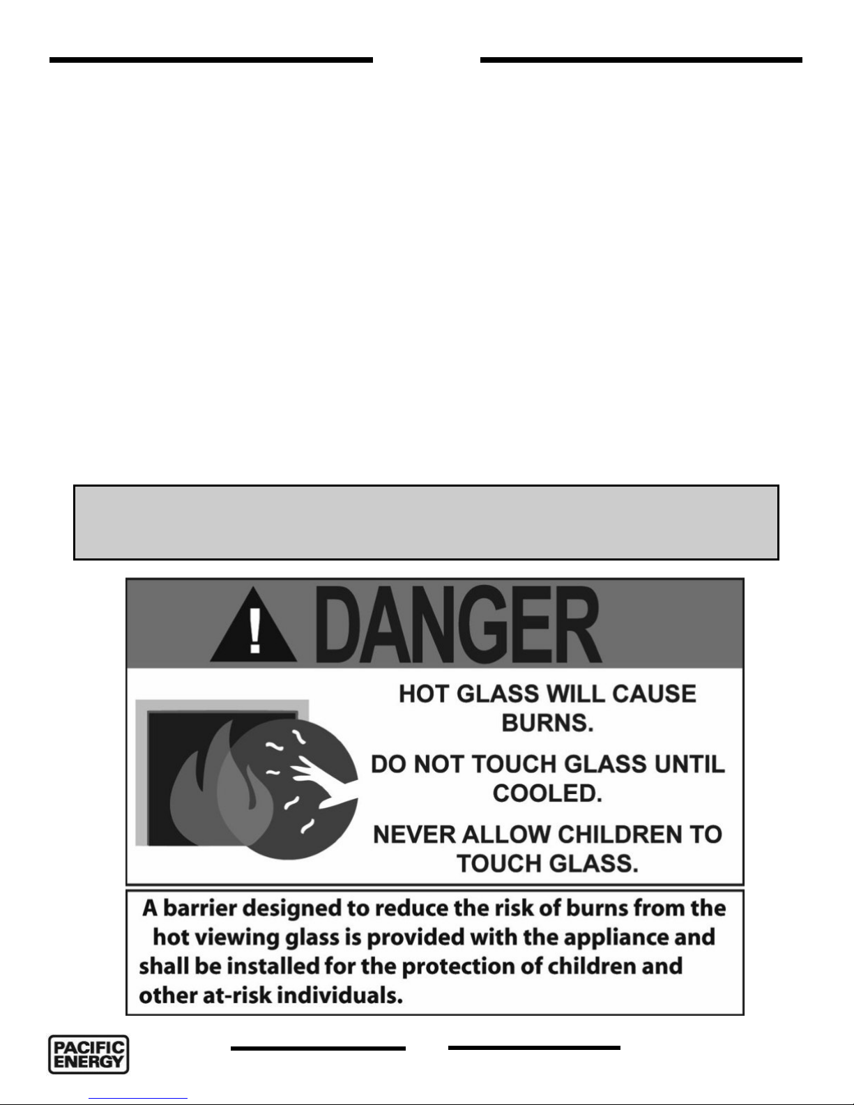
rA barrier designed to reduce the risk of burns from the hot viewing glass is provided with the
Surround Kit component and shall be installed.
rIf the barrier becomes damaged, the barrier shall be replaced with the manufacturers barrier
for this appliance.
rAny grill, panel or door removed for servicing the unit must be replaced prior to operating.
rInstallation and repair should be done by a qualified service person. The appliance should be
inspected before use and at least annually by a professional service person. More frequent
cleaning may be required due to excessive lint from carpeting, bedding material, etc. It is
imperative that control compartments, burners and circulating air passageways of the appliance
be kept clean.
rThis appliance must not be connected to a chimney flue serving a separate solid fuel burning
appliance.
rIt is our policy that no responsibility is assumed by the Company or by any of its employees or
representatives for any damages caused by an inoperable, inadequate, or unsafe condition which
is the result, either directly or indirectly, of any improper operation or installation procedures.
WHAT TO DO IF YOU SMELL GAS
rDo not try to light any appliance.
rDo not touch any electrical Switch.
rDo not use any phone in your building.
rImmediately call your gas supplier from a neighbor’s phone. Follow the gas supplier’s instructions.
rIf you cannot reach your gas supplier call the fire department.
rInstallation and service must be performed by a qualified installer, service agency or the gas
supplier.
5055.990-A
130717-44
5
i30 TOFINO

First Fire
When lit for the first time, the fireplace will emit a slight odour for a couple of hours. This is due to
the curing of paints, sealants and lubricants used in the manufacturing process. This condition is
temporary. Open doors and windows to ventilate area. Odour caused by the curing process may
cause discomfort to some individuals.
It is normal for fireplaces fabricated of steel to give off some expansion and/or contraction noises
during the start up or cool down cycle. Similar noises are found with your furnace heat exchanger or
cook stove oven.
NOTE: Fireplace may take up to
30 seconds to ignite each time the
“ON” button has been selected
Warnings and Cautions
WARNING
Fire Hazard. Can cause severe injury or death
The Receiver causes ignition of the appliance. The appliance can turn on suddenly. Keep away from the
appliance burner when operating the remote system or activating manual bypass of the remote system.
WARNING
Shock Hazard. Can cause severe injury or death
This device is powered by line voltage. Do not try to repair this device. In no way is the enclosure to be
tampered with or opened. Disconnect from line voltage before performing any maintenance.
6
130717-44
5055.990-Ai30 TOFINO
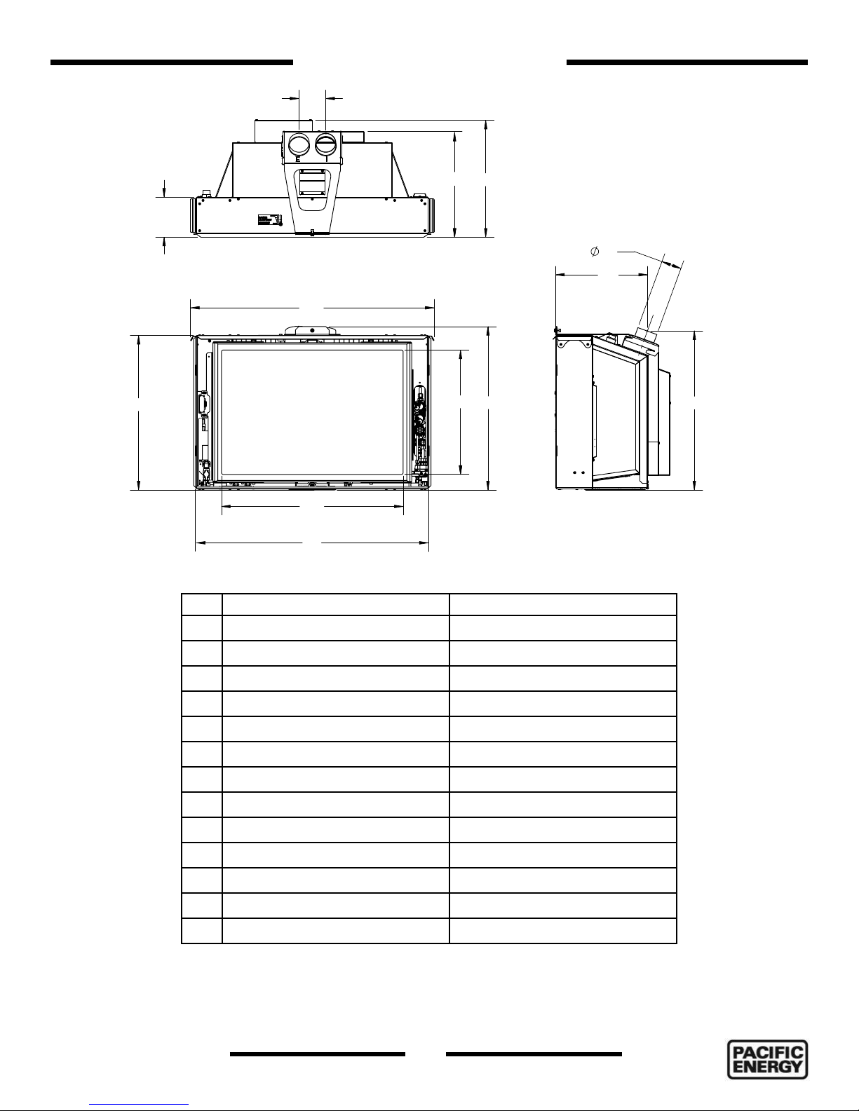
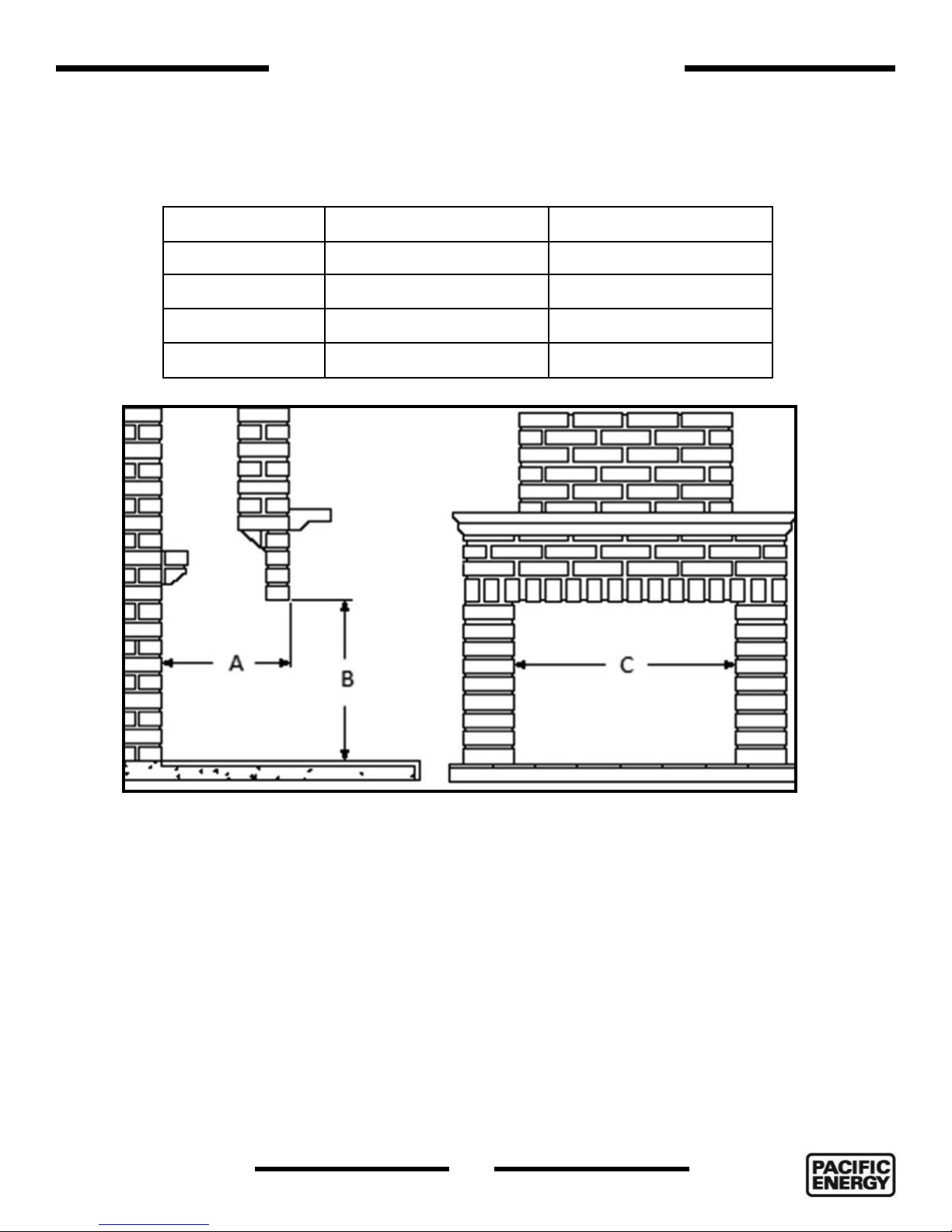
Fireplace Dimensions
A
C
D
B
K
L
E
G
F
H
M
I
J
Figure 1: Tofino Dimensions.
Tofino i30 SIT Tofino i30 Maxitrol
A 4” 4”
B 6” 6”
C 15 1/4” 15 3/4”
D 17 3/8” Use dimension “C”
E 33 3/16” 33 3/16”
F 20 3/8” 20 3/8”
G 16” 16”
H 21 5/8” 21 5/8”
I 24” 24”
J 31 1/2” 31 1/2”
K * 3” x 4” * 3” x 4”
L 13 5/8” 14 3/8”
M 21 1/4” 21 3/4”
* This unit ships with a 3” x 4” air intake and exhaust flue adapter.
5055.990-A
130717-44
7
i30 TOFINO
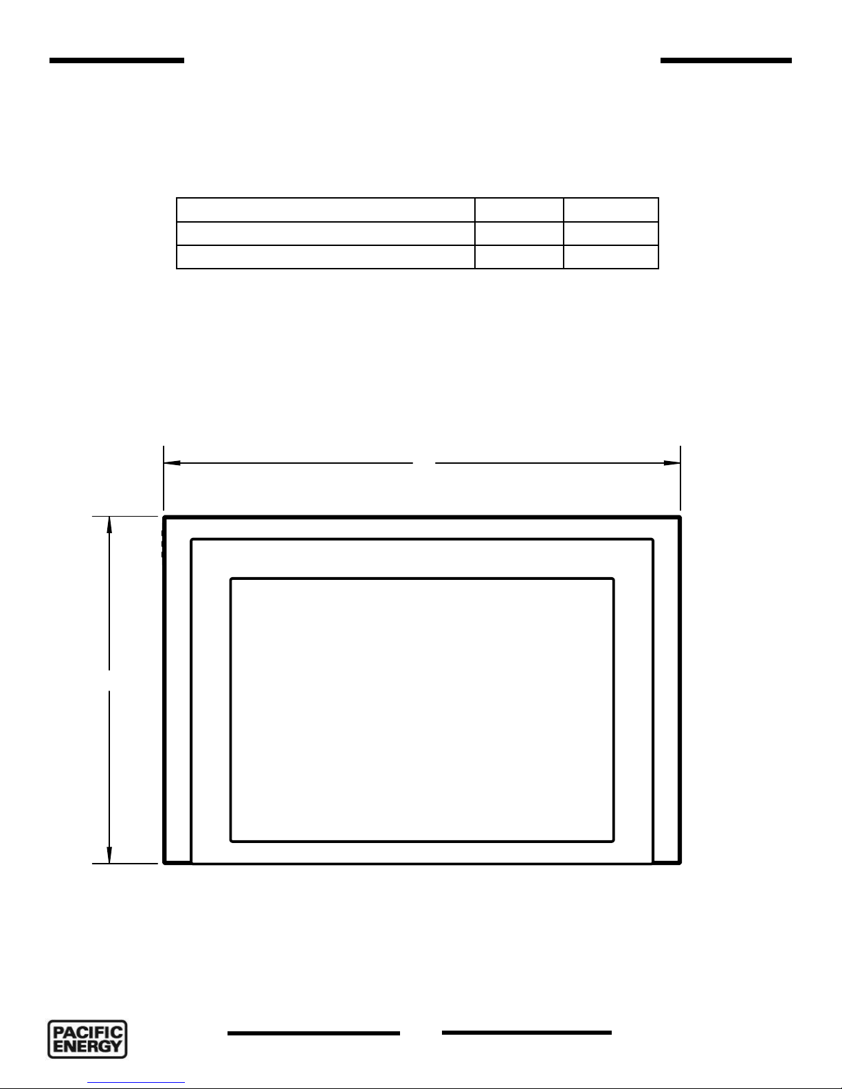
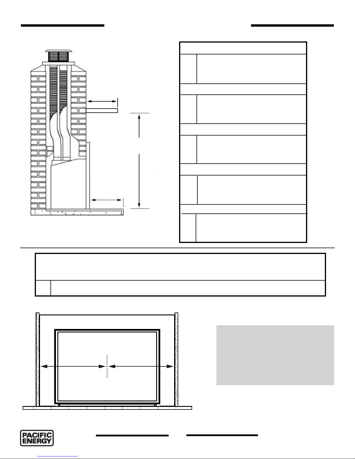
Tofino Insert Backing Plate Dimensions
Tofino i30
HEIGHT / WIDTH A B
REGULAR 26” 38”
OVERSIZED 28” 42”
A
B
Figure 2: Tofino Surround dimensions.
8
130717-44
5055.990-Ai30 TOFINO
Existing Fireplace Preparation
Note: SIT controlled installations require that an electrical outlet be installed into existing fireplace
cavity before insert is installed.
The Tofino Gas inserts are certified to be installed into pre-existing approved fireplace. The minimum existing
opening fireplace requirements are listed in Figure 3 below.
Dimension i30 SIT i30 Maxitrol
A 17 7/8” 16 1/4”
B 22 1/8” 22 1/8”
C without handles 32” 32”
C with handles 33 1/2” 33 1/2”
Figure 3: Minimum openings.
Before installing the Tofino inserts, have the chimney and fireplace swept including ash dumps and clean
outs. Clean and remove any creosote and soot residue that may cause odors and stains after the insert
has been installed. The fireplace chimney should be in good working order and made of non-combustible
material. Make sure chimney clean-outs fit properly.
When preparing an existing fireplace to install a gas insert, any modifications that will compromise the
integrity of the existing fireplace are not allowed. To make way for the inserts’ venting, the fireplace flue
dampener may be blocked open or removed. Refractory, glass doors, screen rails, screen mesh and log
grates can be removed from the fireplace before installing the insert. Also, smoke shelves, shields and baffles may be removed if attached by mechanical fasteners. Cutting any sheet metal parts of the fireplace, in
which the gas fireplace insert is to be installed, is prohibited.
If the factory-built fireplace has no gas access hole(s) provided, an access hole of 1.5” dia. (37.5mm) or
less may be drilled through the lower sides or bottom of the firebox in a proper workmanship like man-
ner. This access hole must be plugged with non-combustible insulation after the gas supply line has been
installed.
5055.990-A
130717-44
9
i30 TOFINO
Clearances to Combustibles
Mantel Clearances
Mantel Depth
Clearance
Figure 4: Mantel clearance.
Mantel Clearance
Hearth
i30
35”
Mantel Depth
i30
14”
Hearth Clearance
i30
0”
Objects in front of Appliance
i30
36”
Under Appliance
i30
0”
Horizontal Clearances
Horizontal clearance to adjacent sidewall combustibles. Refer to Figure 5
i30
18” From center of fireplace to nearest combustible or to backing plate, whichever is furthest
Side wall
Figure 5: Horizontal clearance to combustibles.
Side wall
rFireplace Surround Fronts
located on page 37.
rFireplace Surrounds and oversize
backing plates for larger fireplace
openings located on page 37.
rFronts and Surrounds part numbers
located in Service Manual .
10
130717-44
5055.990-Ai30 TOFINO
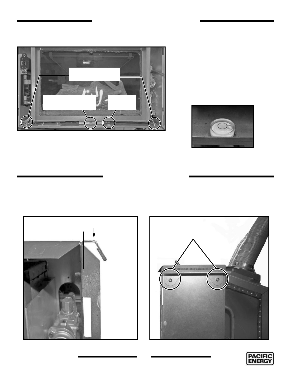
Adjustable leveling bolts
Side to side levelling
adjustments
Rear to front levelling
adjustment
Figure 6: Leveling adjustments.
Adjustable Leveling Bolts
This fireplace comes with two leveling bolts
used to adjust the angle of the front of
the fireplace relative to the wall in which
it’s installed (Figure 6). The bolts are preinstalled. There is also a single rear leveling
adjustment bolt located at the center of the
bottom floor. Use these adjustments along
with the bubble sight (Figure 7) to level the
Bubble
sight
Tofino fireplace.
Figure 7: Bubble sight.
Removable Handles
The handles used to lift and maneuver the Tofino into position can be removed in order to accommodate a
narrower horizontal fireplace opening. By removing each of the two handles, a full 1 1/2” can be saved.
3/4”
Handle screws
Figure 8: Removable handles.
5055.990-A
130717-44
Figure 9: Removable handle screws.
11
i30 TOFINO
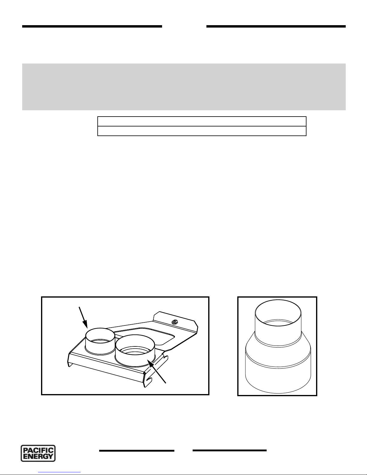
Venting
Installation Advisory
The i30 comes from the factory with a 3” intake and a 4” exhaust configuration. Whenever possible, this
configuration should be used. However, a 4” to 3” optional reducer (Figure 11) can be used on the exhaust
for venting lengths between 10’ and 28’ if necessary. Be advised that using this optional adapter may have
an impact on flame appearance and is not recommended for use with the glass burner option while operating with propane gas.
10’ to 40’ Use the 3x4 Configuration
10’ to 28’ Use the 3x4 and the 4” to 3” adapter Configuration
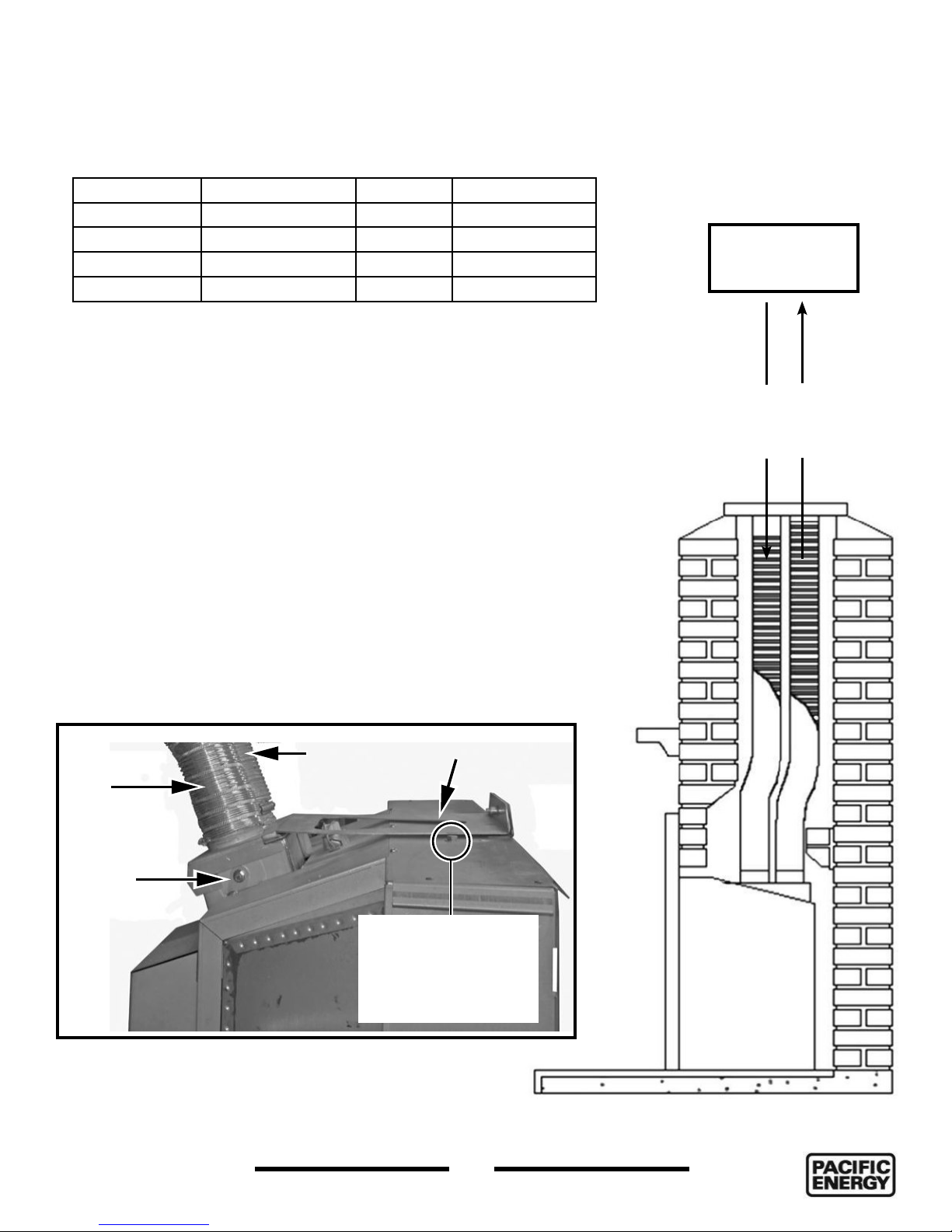
Installation Tip
Depending on the amount of room available for the installation of the Tofino, the installer may want to remove
the flue adapter and attach it to the flex tubes which will have previously been inserted down the chimney.
The installer must make sure that the air intake vent and air exhaust vents attach to the correct ports on
both the flue adapter and the vent terminal. The vent terminal and the flue adapter are marked with an “I” (air
intake) and “E” (air exhaust).
Optional 4” to 3” exhaust adapter
Part number for the optional 4” to 3” exhaust adapter is 1227.0003.
3” Air intake
4” Exhaust
Figure 10: 4 x 3 inch Flue adapter.
Figure 11: 4 inch to 3 inch
exhaust adapter.
12
130717-44
5055.990-Ai30 TOFINO
Only certified venting systems or components may be installed with this fireplace.
Only the following vent terminals should be used for the
Tofino i30.
Manufacturer Model Model # venting length
Duravent high wind terminal DVA-CL33 10’ to 28’
Duravent high wind terminal DVA-CL34 10’ to 40’
ICC Co linear terminal CT3 10’ to 28’
ICC Co linear terminal CT4 10’ to 40’
1. Measure chimney height, cut flex liner (min.10’) as required. Mark
one pipe at both ends to identify combustion air intake pipe from
flue outlet pipe.
2. Attach marked flex liner pipe to the intake side of vent terminal. Seal
Combustion
Air Intake
and secure with sealant and screws provided. Attach the other pipe
to the outlet side of vent terminal. Seal and secure with sealant and
screws provided.
3. Insert both flex liners from top of the chimney, down through the
damper opening.
4. Attach and seal according to vent terminal manufacturers’ instructions
5. For larger chimneys, a flashing may be cut and fitted to suit. Caulk
the flashing in place to seal any gaps.
Max Vent Height
40’ (12.2m)
Min. Vent Height
10’ (3m)
Certified vent
terminal
Exhaust
Vent
Exhaust
vent
Damper
linkage
Figure 12: Flue adapter components.
5055.990-A
130717-44
Combustion
air intake
Damper adjustment
securing bolt.
(Adjustment handle
located under top
surface
Flue adapter
13
Figure 13: Co linear venting.
i30 TOFINO
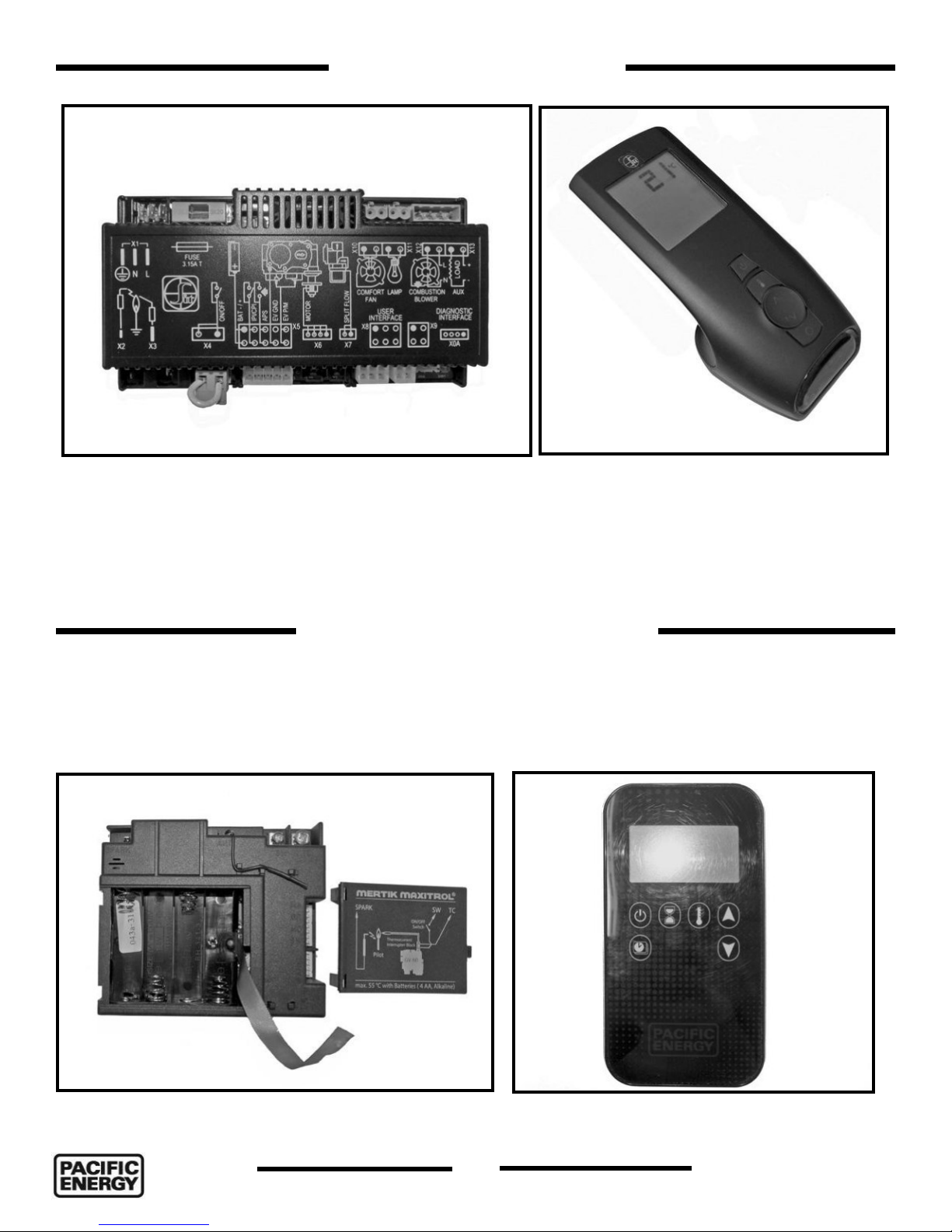
SIT Control Overview
Figure 14: SIT Proflame controller module.
The SIT Proflame controller (Figure 14) is used along with the SIT Proflame gas valve (See “Figure 38” on
page 20) . The use of the SIT Proflame controller requires a remote control device (provided) unique to the
SIT Proflame configuration. Instructions for using the SIT Proflame remote control device are found Tofino
Operating Instructions manual. The SIT module uses 4 AA batteries. The SIT Proflame remote control unit
uses 3 AAA batteries.
Figure 15: Proflame - SIT remote control device.
Maxitrol Control Overview
The Maxitrol controller (Figure 16) is used along with the Maxitrol gas valve (Figure 40 on page 21). The
use of the Maxitrol controller requires a remote control device (provided) unique to the Maxitrol configuration.
Instructions for using the Maxitrol remote control device are found in the Tofino Operating Instructions manual.
The Maxitrol module uses 4 AA batteries. The Maxitrol romote control unit takes 2 AAA batteries.
Figure 16: Maxitrol module.
Figure 17: Remote control for the Maxitrol
configuration.
14
130717-44
5055.990-Ai30 TOFINO
 Loading...