

Pacific energy TOFINO i20 Operating Instructions Manual
OPERATING INSTRUCTIONS
INSTALLER:
Leave this manual with the appliance.
CONSUMER:
Retain this manual for future reference.
WARNING: If the information in these
instructions is not followed exactly a fire
or explosion may result causing property
damage, personal injury or death.
FOR YOUR SAFETY
Do not store or use gasoline or other flammable
vapours and liquids in the vicinity of this or any
other appliance.
WHAT TO DO IF YOU SMELL GAS
• Do not try to light any appliance.
• Do not touch any electrical Switch.
• Do not use any phone in your building.
• Immediately call your gas supplier from a
neighbour’s phone. Follow the gas supplier’s
instructions.
• If you cannot reach your gas supplier call the
fire department.
Installation and service must be performed by
a qualified installer, service agency or the gas
supplier.
TOFINO OPERATING
INSTRUCTIONS
This appliance may be installed in an aftermarket
permanently located, manufactured home (USA
only) or mobile home, where not prohibited by
local codes.
This appliance is only for use with the type of
gas indicated on the rating plate. This appliance
is not convertible for use with other gases
unless a certified kit is used.
This appliance is suitable for installation in a
bedroom or bed sitting room.
Visit www.pacificenergy.net for the most recent version of this manual
150317-32
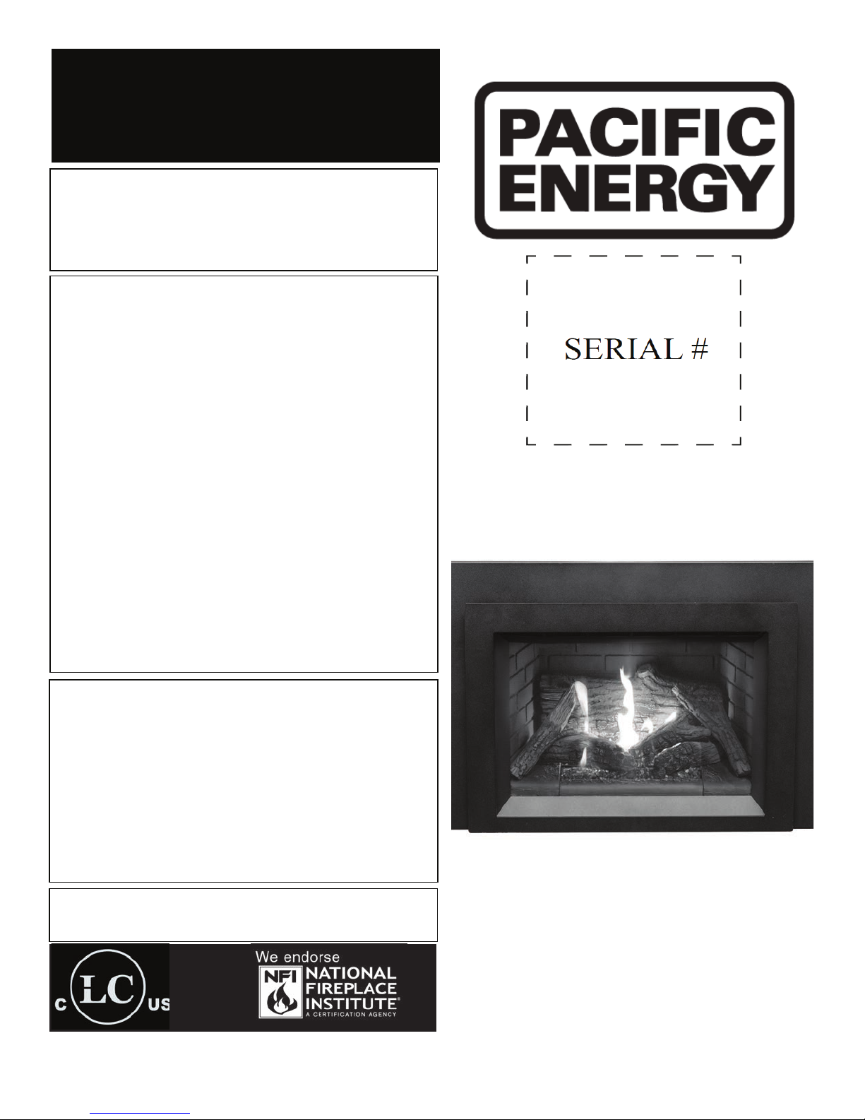
TOFINO
MODEL: TOFINO i20
(SIT & Maxitrol versions)
SERIES: A
DIRECT VENT GAS INSERT
5055.980-A
Table Of Contents
Caution ...................................................................................... 3
Safety ........................................................................................ 4
WHAT TO DO IF YOU SMELL GAS ................................... 4
First Fire ..................................................................................... 5
Warnings and Cautions ............................................................. 5
Remote Control Operation (SIT Proame) ................................. 6
System Description .......................................................... 6
Transmitter (Remote Control with LCD Display) ............... 6
IFC Module .........................................................................7
Operating Procedure ..........................................................7
Initializing the system for the rst time ...............................7
Temperature indication Display .......................................... 9
Turn on the Fireplace .......................................................... 9
Turn off the Fireplace ......................................................... 9
Manual Bypass of the Remote System .............................. 9
Key Lock ............................................................................ 9
Room Thermostat (Transmitter Operation) ..................... 9
Remote Flame Control .................................................... 10
Split Flow Function .......................................................... 10
Smart Thermostat (Transmitter Operation) ......................11
Comfort Fan Speed Control ..............................................11
Low Battery Power Detection .......................................... 12
Transmitter ....................................................................... 12
Receiver ........................................................................... 12
Continuous Pilot/Intermittent Pilot (CPI/IPI) selection .... 12
Remote Control Operation (Maxitrol) ....................................... 13
Operating Instructions...................................................... 13
Setting the Electronic Code ............................................. 14
Setting Fahrenheit or Celsius ........................................... 15
Setting the Time ............................................................... 15
Child Proof ....................................................................... 15
Manual mode (handset) ................................................... 15
Handset One-Button Operation ....................................... 16
Handset Two-Button Operation ....................................... 16
Standby Mode (Pilot Flame) ............................................. 16
To Turn Off Fire ................................................................. 16
Flame Height Adjustment..................................................17
Designated Low Fire and High Fire ...................................17
Countdown Timer ............................................................ 18
Modes of Operation ......................................................... 18
Thermostatic Mode .......................................................... 19
Program Mode ................................................................. 19
To turn on appliance ......................................................... 22
To Turn Off Gas Appliance. ............................................... 23
Automatic Turn Down ....................................................... 23
Automatic Shut Off ........................................................... 23
On-Demand Pilot ............................................................. 23
Receiver ........................................................................... 24
Lighting Instructions ................................................................ 25
Maintenance ............................................................................ 26
Glass Door: ...................................................................... 26
Periodically: ...................................................................... 26
Surround Installation/Removal Instructions .............................27
Removal ............................................................................27
Installation .........................................................................27
Door Installation/Removal ........................................................ 28
Removal ........................................................................... 28
Installation ........................................................................ 28
5055.980-A
2
150317-32
i20 TOFINO
Caution
FOR YOUR SAFETY - Do not install or operate your Pacic Energy replace without rst reading
and understanding this manual. Any installation or operational deviation from the following instructions voids the Pacic Energy Fireplace Warranty and may prove hazardous.
This appliance and its individual shut off valve must be disconnected from gas supply piping system
during any pressure testing of that system at test pressures in excess of 1/2 psig (3.5 kPa).
This appliance must be isolated from the gas supply piping system by closing its individual manual
shut off valve during any pressure testing of the gas supply piping system at test pressures equal to
or less than 1/2 psig (3.5 kPa).
Note: When lit for the rst time, the appliance will emit a slight odour for a couple of hours. This
is due to the curing of paints, sealants and lubricants used in the manufacturing process. This
condition is temporary. Open doors and windows to ventilate area. Smoke and fumes caused by the
curing process may cause discomfort to some individuals.
Do not use the replace if any part has been under water. Immediately call a qualied service
technician to inspect the replace and to replace any part of the control system and any gas control
which has been under water.
This replace is equipped with a micro mesh safety screen for your protection and
must be installed with the unit. Removal of the safety screen will cause the replace
to become a burn hazard.
i20 TOFINO
150317-32
3
5055.980-A

Safety
• Due to high temperatures, this gas appliance should be located out of trafc and away from
furniture and draperies.
• Children and adults should be alerted to the hazards of high surface temperatures and should
stay away to avoid burns or clothing ignition.
• Young children should be carefully supervised when they are in the same room as the appliance.
Toddlers, young children and others may be susceptible to accidental contact burns. A physical
barrier is recommended if there are at risk individuals in the house. To restrict access to a
replace or stove, install an adjustable safety gate to keep toddlers, young children and other at
risk individuals out of the room and away from hot surfaces.
• Clothing or other ammable material should not be placed on or near the appliance.
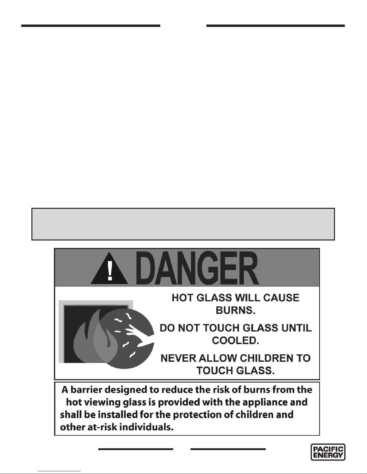
• A barrier designed to reduce the risk of burns from the hot viewing glass is provided with the
Surround Kit component and shall be installed.
• If the barrier becomes damaged, the barrier shall be replaced with the manufacturers barrier
for this appliance.
• Any grill, panel or door removed for servicing the unit must be replaced prior to operating.
• Installation and repair should be done by a qualied service person. The appliance should be
inspected before use and at least annually by a professional service person. More frequent
cleaning may be required due to excessive lint from carpeting, bedding material, etc. It is
imperative that control compartments, burners and circulating air passageways of the appliance
be kept clean.
• This appliance must not be connected to a chimney ue serving a separate solid fuel burning
appliance.
• It is our policy that no responsibility is assumed by the Company or by any of its employees or
representatives for any damages caused by an inoperable, inadequate, or unsafe condition which
is the result, either directly or indirectly, of any improper operation or installation procedures.
WHAT TO DO IF YOU SMELL GAS
• Do not try to light any appliance.
• Do not touch any electrical Switch.
• Do not use any phone in your building.
• Immediately call your gas supplier from a neighbor’s phone. Follow the gas supplier’s instructions.
• If you cannot reach your gas supplier call the re department.
• Installation and service must be performed by a qualied installer, service agency or the gas
supplier.
5055.980-A
4
150317-32
i20 TOFINO

Congratulations on your purchase of a Pacifi c Energy Gas Appliance.
Your replace has been professionally installed by:
Dealer name: ___________________________________________________
Phone Number:___________________________________________________
If you discover any problems with your gas appliance contact your dealer immediately to have the
unit repaired.
Caution: Do not attempt to repair the replace because you may cause injury to yourself or others,
and risk causing damage to the unit.
Before operating your appliance carefully read this manual and pay close attention to all Safety
Warnings.
The manual contains important information on the unit’s safe operation and maintenance.
First Fire
When lit for the rst time, the replace will emit a slight odour for a couple of hours. This is due to
the curing of paints, sealants and lubricants used in the manufacturing process. This condition is
temporary. Open doors and windows to ventilate area. Odour caused by the curing process may
cause discomfort to some individuals.
It is normal for replaces fabricated of steel to give off some expansion and/or contraction noises
during the start up or cool down cycle. Similar noises are found with your furnace heat exchanger or
cook stove oven.
NOTE: Fireplace may take up to
30 seconds to ignite each time the
“ON” button has been selected
Warnings and Cautions
WARNING
Fire Hazard. Can cause severe injury or death
The Receiver causes ignition of the appliance. The appliance can turn on suddenly. Keep away from the
appliance burner when operating the remote system or activating manual bypass of the remote system.
WARNING
Shock Hazard. Can cause severe injury or death
This device is powered by line voltage. Do not try to repair this device. In no way is the enclosure to be
tampered with or opened. Disconnect from line voltage before performing any maintenance.
i20 TOFINO
150317-32
5
5055.980-A
Remote Control Operation (SIT Profl ame)
System Description
The Pro ame 2 Remote Control System consists of two elements:
1. Pro ame 2 Remote Control Transmitter.
2. Pro ame Integrated Fireplace Control (IFC) (Figure 3) board and a wiring harness to connect the IFC to
the gas valve and stepper motor.
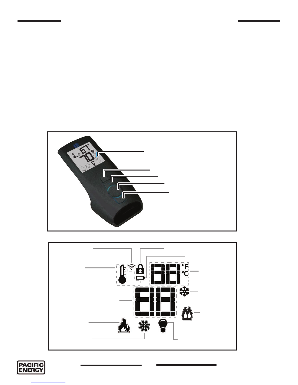
Transmitter (Remote Control with LCD Display)
The Pro ame 2 Transmitter uses a streamline design with a simple button layout and informative LCD
display (Figure 1). The transmitter is powered by 3 AAA type batteries. A Mode key is provided to Index
between the features and a Thermostat key is used to turn on/off or index through thermostat functions
(Figure 1 and Figure 2).
Blue back lit LCD display
Figure 1: Pro ame 2 handset.
TRANSMISSION
THERMOSTAT OFF/
ON/SMART
SET POINT:
TEMPERATURE/LEVEL/STATE
OFF
ON
SMART
ON/OFF Key
THERMOSTAT Key
UP/DOWN Arrow Key
MODE Key
KEY LOCK
LOW BATTERY ALARM
ROOM
TEMPERATURE
CPI MODE
FLAME LEVEL
COMFORT FAN
Figure 2: Pro ame 2 LCD display.
5055.980-A
MAX MAX
6
DIMMER ON
SPLIT FLOW
150317-32
i20 TOFINO

IFC Module
The Proame 2 Integrated Fireplace Control (IFC) module (Figure 3) is a device that allows automatic ignition
and pilot ame supervision, and commands the functions of the hearth Heater. It’s congured to control the
ON/OFF main burner operation, giving the choice of both IPI (intermittent pilot ignition), and CPI (continuous
pilot ignition) modes. The Proame 2 IFC module controls and connects directly to the pilot assembly and the
automatic valve using low electric power.
The IFC module can be powered by both an AC power supply, and battery pack for back up. The Proame
2 offers the added ability to control the comfort fan speed from OFF through six (6) speeds, a remotely
actuated auxiliary outlet and a dimmable light outlet. The external batteries can provide DC power to the IFC
allowing the batteries to be used only when line power is interrupted or lost, and if the Heater does not use a
combustion fan.
Operating Procedure
Initializing the system for the rst time.
1. Install 4 AA batteries into the battery holder located behind the electronic control module on the pull - out
caddy.
2. Install 3 AAA batteries into the Proame 2 Remote Transmitter (Figure 1).
3. Plug the power cord into the Tono and open the gas supply line.
4. With the front surround (Figure 47 on page 28) and backing plate (Figure 48 on page 28) removed,
press the button marked “PRG” on the caddy (Figure 3) once. The module will beep 3 times indicating
that it is ready to synchronize with a remote transmitter.
5. On the remote transmitter, push the power on button once. The remote transmitter will beep 4 times to
indicate that the remote transmitter and the control module are now synchronized. The remote transmitter
is now ready to use.
i20 TOFINO
150317-32
7
5055.980-A
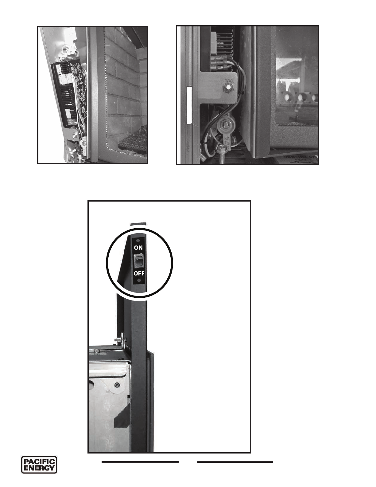
PRG
Figure 3: SIT electronic controller (IFC)
mounted onto caddy.
Figure 4: Program button.
ON
REMOTE
OFF
Figure 5: On Off switch for SIT units.
5055.980-A
8
150317-32
i20 TOFINO
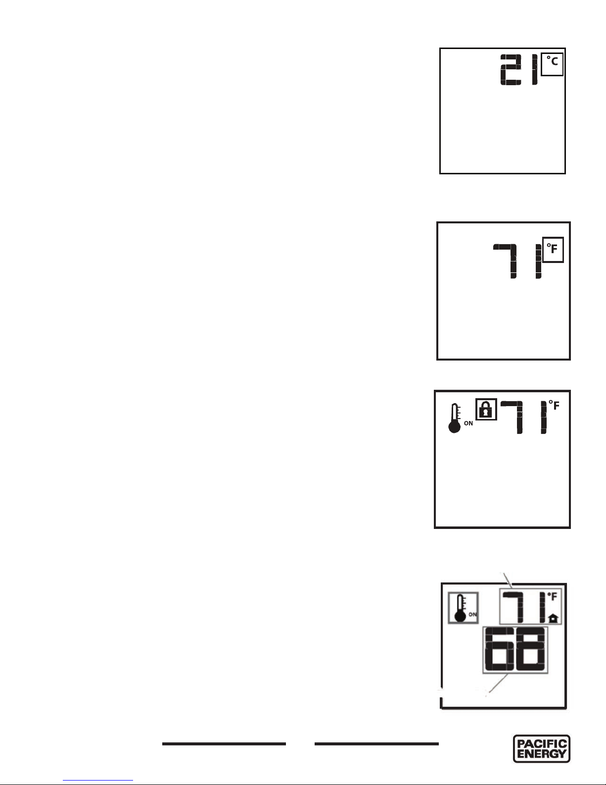
Temperature indication Display
With the system in the “OFF” position, press the Thermostat Key and the
Mode Key at the same time. Look at the LCD screen on the transmitter to
verify that a C or F is visible to the right of the Room Temperature display
(Figure 6 and Figure 7).
Turn on the Fireplace
With the system OFF, press the ON/OFF Key on the remote transmitter. The
remote transmitter display will show some other active Icons on the screen.
At the same time the Receiver will activate the Heater. A single “beep” from
the Receiver (module) will conrm reception of the command.
Turn off the Fireplace
With the system ON, press the ON/OFF Key on the Remote transmitter.
The Remote transmitter LCD display will only show the room temperature
(Figure 6 and Figure 7). At the same time the Receiver (module) will turn off
the Heater. A single “beep” from the Receiver conrms reception of the
command.
Manual Bypass of the Remote System
If the batteries of the receiver or remote transmitter are low or depleted, the
Heater can be turned off manually using ON/OFF switch located on the
left hand side of the backing plate (Figure 5). This will bypass the remote
transmitter.
Figure 6: Temperature in
celcius.
Figure 7: Temperature in
fahrenheit.
Key Lock
This function will lock the keys to avoid unsupervised operation. To activate
this function, press the MODE and UP keys at the same time. The lock icon
will appear (Figure 8). To de-activate this function, press the MODE and UP
keys at the same time.
Room Thermostat (Transmitter Operation)
The Remote Control can operate as a room thermostat. The thermostat
can be set to a desired temperature to control the comfort level in a room.
To activate this function, press the Thermostat key (Figure 1). The LCD
display on the transmitter will change to show that the room thermostat
is “ON” and the set temperature is now displayed (Figure 9). To adjust
the set point, press the up or down arrow keys until the desired set point
temperature is displayed on the LCD screen of the transmitter.
i20 TOFINO
150317-32
9
Figure 8: Key lock icon.
Room Temperature
Set Temperature
Figure 9: Room temperature control.
5055.980-A
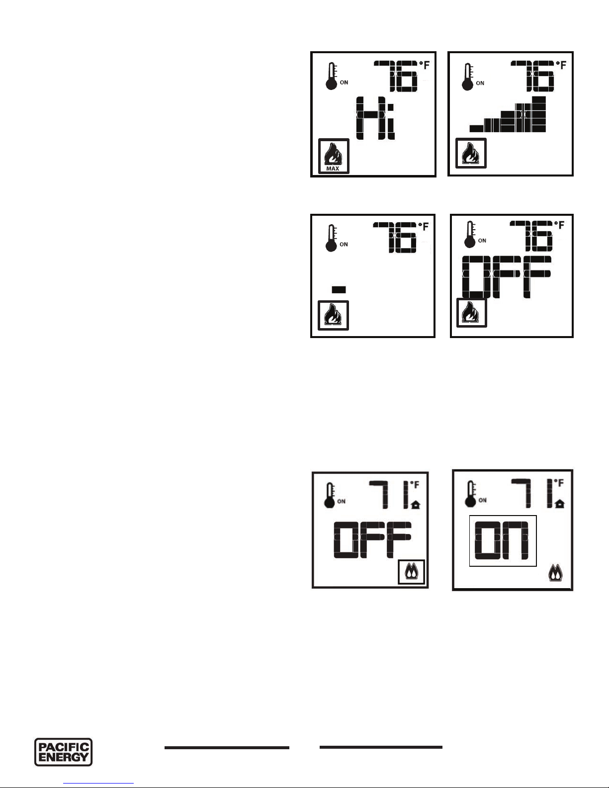
Remote Flame Control
The Pro ame has six (6) ame levels. With the
system on, and the ame level at the maximum in
the appliance, pressing the down arrow key once will
reduce the ame height by one step until the ame is
turned off.
The Up Arrow Key will increase the ame height each
time it is pressed. If the Up Arrow Key is pressed
while the system is on but the ame is off, the ame
will come on in the high position (Figure 10). A single
“beep” will con rm reception of the command.
Flame level Max
Flame level 5
Split Flow Function
The secondary burner is controlled by the split ow.
To activate this function, use the Mode Key (Figure
1) to index to the SPLIT FLOW icon (Figure 11 and
Figure 12). Pressing the Up Arrow Key will activate
the secondary burner. Pressing the Down Arrow
Key will turn the secondary burner off. A single
“beep” will con rm the reception of the command.
Flame level 1
Figure 10: Flame level control.
Figure 11: Split ow Off.
Flame Off
Figure 12: Split ow ON.
5055.980-A
10
150317-32
i20 TOFINO
 Loading...