

Pacific energy The Oxford Installation And Operating Instructions Manual
IMPORTANT:
THESE INSTRUCTIONS ARE TO
REMAIN WITH THE
HOMEOWNER
WARNING: If the information in these
instructions is not followed exactly, a fire
or explosion may result causing property
damage, personal injury or loss of life.
-- Do not store or use gasoline or other
flammable vapours and liquids in the
vicinity of this or any other appliance.
-- WHAT TO DO IF YOU SMELL GAS
• Do not try to light any appliance.
• Do not touch any electrical switch; do
not use any phone in your building.
• Immediately call your gas supplier from
a neighbour’s phone. Follow the gas
f i r e - p a r t s . c o m
supplier’s instructions.
• If you cannot reach your gas supplier,
call the fire department.
--Installation and service must be
performed by a qualified installer, service
agency or the gas supplier.
This appliance may be installed in an
aftermarket permanently located,
manufactured (mobile) home, where not
prohibited by local codes.
This appliance is only for use with the type
of gas indicated on the rating plate. This
appliance is not convertible for use with
other gases, unless a certified kit is used.
The
Oxford
SERIES A
DIRECT VENT HEATER
INSTALLATION
AND OPERATING
INSTRUCTIONS
040400-24 OXFORD-A 5056.421
Contents
CAUTION ....................................................................................... 3
SAFETY.......................................................................................... 3
MAINTENANCE ............................................................................. 3
CONTROL ASSEMBLY ................................................................. 4
GAS SUPPLY................................................................................. 5
FLOOR PROTECTION ................................................................... 5
CLEARANCES ............................................................................... 5
INSTALLATION PRECAUTIONS .................................................. 6
STRAIGHT THROUGH WALL INSTALLATION ............................ 7
CORNER INSTALLATION ............................................................. 8
BASEMENT INSTALLATION ...................................................... 10
ATTACHMENT TO FLOOR ......................................................... 10
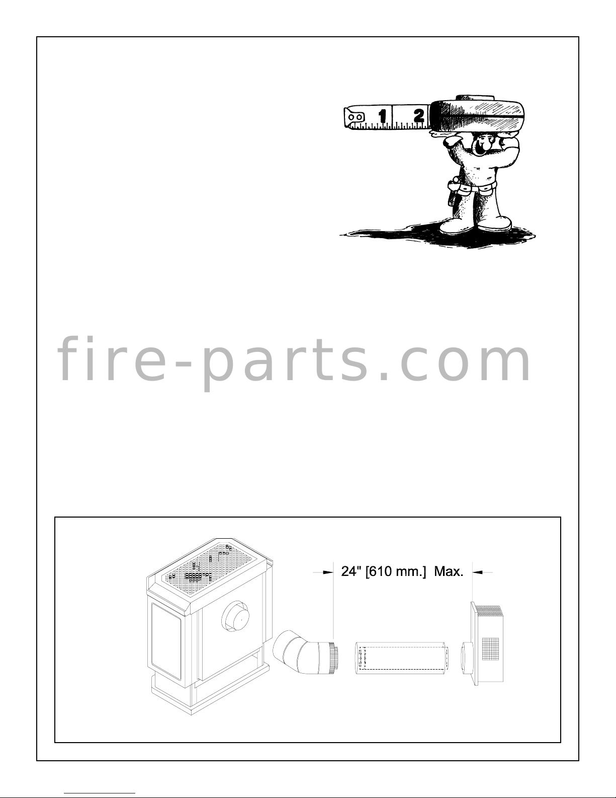
ALTERNATE VENTING ............................................................... 11
VENT TERMINAL INSTALLATION ............................................. 15
GLASS FRONT REMOVAL ......................................................... 16
LOG SET ...................................................................................... 17
GLOWING EMBERS .................................................................... 17
FIRST FIRE .................................................................................. 19
OPERATION ................................................................................ 19
f i r e - p a r t s . c o m
PRIMARY AIR ADJUSTMENT..................................................... 19
OPTIONAL WALL SWITCH OR THERMOSTAT......................... 20
OPTIONAL BLOWER .................................................................. 20
REPLACEMENT PARTS ............................................................. 21
RATING LABEL ........................................................................... 23
2

MAINTENANCE
Important: When lit for the first time, the appliance will emit
a slight odour for a couple of hours. This is due to the curing
of paints, sealants and lubricants used in the manufacturing
process. This condition is temporary. Open doors and
windows to ventilate area. If optional fan kit has been
installed, place fan in the "OFF" position. Smoke and fumes
caused by the curing process may cause discomfort to some
individuals.
It is normal for fireplaces fabricated of steel to give off some
expansion and/or contraction noises during the start up or cool
down cycle. Similar noises are found with your furnace heat
exchanger or cook stove oven.
CAUTION
FOR YOUR SAFETY - Do not install or operate your Pacific Energy
fireplace without first reading and understanding this manual. Any
installation or operational deviation from the following instructions
voids the Pacific Energy Warranty and may prove hazardous.
This appliance and its individual shutoff valve must be disconnected
from gas supply piping system during any pressure testing of that
system at test pressures in excess of 1/2 psig. (3.5 kPa).
This appliance must be isolated from the gas supply piping system by
closing its individual manual shutoff valve during any pressure testing
of the gas supply piping system at test pressures equal to or less than
f i r e - p a r t s . c o m
1/2 psig. (3.5 kPa).
SAFETY
• Due to high temperatures, this gas appliance should be
located out of traffic and away from furniture and draperies.
• Children and adults should be alerted to the hazards of high
surface temperatures and should stay away to avoid burns or
clothing ignition.
• Young children should be carefully supervised when they are
in the same room as the appliance.
Caution: Turn off gas and electrical power supply and allow ample
time for unit to cool before servicing appliance. It is recommended that
this appliance and venting should be inspected at least once a year by
a qualified service person.
Do not use this heater if any part has been under water. Immediately
call a qualified service technician to inspect the heater and to replace
any part of the control system or gas control which has been under
water.
Glass Front
Warning: Do not operate appliance with glass panel removed,
cracked or broken. Replacement of glass should be done by a
licensed or qualified service person.
Do not strike or otherwise impact the glass in anyway that may cause
it to break. If the glass becomes cracked or broken, it must be replaced
before using the fireplace. Replacement glass con be obtained from
your nearest Pacific Energy dealer. The size required is 12 9/16" x 19
5/8" x 5mm. Use ceramic glass only. Do not substitute with any
other type.
To remove broken glass, remove the front window overlay to access
wing nuts at the bottom of the window frame. Undo wing nuts and
swing the bottom out to clear. Lift up and forward to disengage from
the top. Remove all particles of glass. Be careful as they are very
sharp. Install new glass complete with gasket. Replace frame and
overlay in reverse order.
Annual Inspection:
a) Clean air passage ways of excessive lint and dust build-up from
carpeting, bedding material, etc. The flow of ventilation air must not be
obstructed.
b) Remove glass panel and log set. Inspect logs and burner
assembly for lint and soot build-up. If excessive build-up of soot is
present, have a qualified service person inspect and adjust unit for
proper combustion. Clean logs and burner with a vacuum cleaner,
paying close attention to the ports on the burner.
c) Check the pilot system for proper flame size and operation. Clean
pilot free of lint and dust. (See Fig. #1)
d) Check that the vent pipe and vent terminal are open and free from
blockage or debris. If the venting system is disassembled for cleaning,
it must be properly assembled and resealed. Refer to VENTING
section for proper procedure.
e) Check glass panel gasket, replace if necessary. It is important that
the glass seal be maintained in good condition.
Note: The appliance area must be kept clear and free from combustible materials, gasoline and other flammable vapours and liquids.
• Clothing or other flammable material should not be placed on
or near the appliance.
• Under no circumstances should this fireplace be modified.
Any grill, panel or door removed for servicing the unit must be
replaced prior to operating. Failure to do so may create a
hazardous condition.
• Installation and repair should be done by a qualified service
person. The appliance should be inspected before use and at
least annually by a professional service person. More frequent
cleaning may be required due to excessive lint from carpeting,
bedding material, etc. It is imperative that control compartments,
burners and circulating air passageways of the appliance be kept
clean.
It is Pacific Energy’s policy that no responsibility is assumed by
the Company or by any of its employees or representatives for
any damages caused by an inoperable, inadequate, or unsafe
condition which is the result, either directly or indirectly, of any
improper operation or installation procedures.
Periodically:
a) Viewing glass may be cleaned with fireplace glass cleaner.
b) Exterior finish may be cleaned with mild soap and water.
Caution: - do not use abrasive cleaners on glass or any other part of
this appliance.
- do not clean glass when hot.
Fig. # 1
3
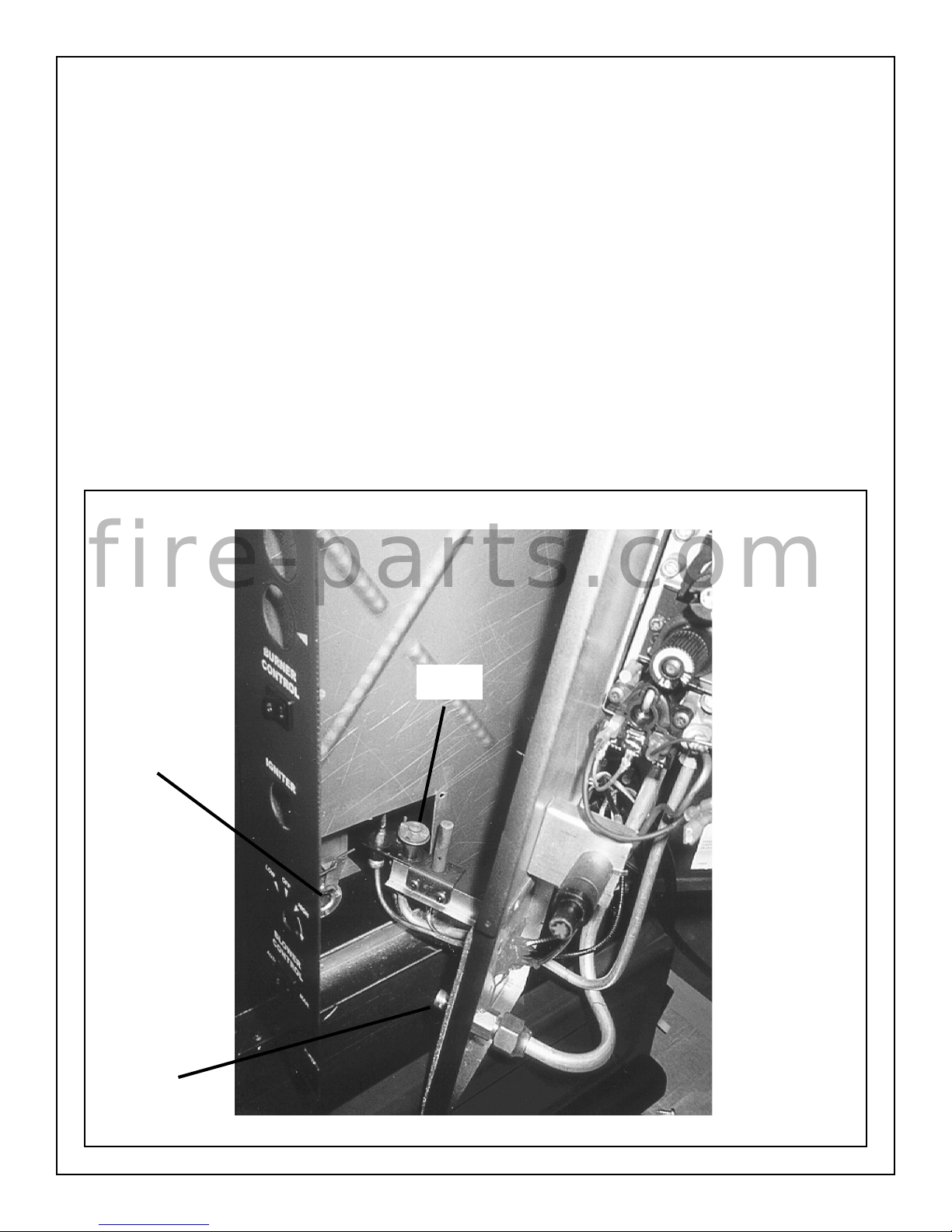
CONTROL ASSEMBLY
Unpack the control valve assembly and inspect all components. Do
not install if damaged. Remove packaging from the appliance.
1) Open control door to access side panel retaining screws. Loosen
screws and swing right side panel open. Note the position of the
screws relative to the panel for later reassembly.
2) Install the flexible gas line connector onto valve.
3) With the controls facing forward and the pilot on the left hand side
proceed to install the valve assembly (see Fig. # 2). Feeding the pilot
through the firebox opening, ensure that the burner orifice inserts into
the end of the venturi tube. When installed properly, the valve
assembly will sit flat against the side of the firebox.
4) Fasten in place with six #8 x 1/2" sheet metal screws provided; two
screws at the top, two in the middle and two at the bottom of the control
assembly.
5) Connect burner switch wires to the back of the rocker switch.
6) Insert valve knob extensions through the control panel and onto
their corresponding valve knobs.
Fig. # 2
7) Install optional blower kit, if it is to be installed. See "OPTIONAL
BLOWER" section for details.
Caution: Before making wiring connections, ensure all electrical
power is disconnected!
8) The gas connection may now be made. See "GAS SUPPLY"
section for details.
9) Place the self-adhesive label on the rating label into the blank box
provided to designate the type of gas the appliance is connected to.
The rating plate is located on the left side of the pedestal base.
After all gas connections are checked and operation of the unit is
verified, the side panel may be closed. Line up the slots in the control
panel with screws in front edge of the side panel. Adjust the side panel
so that the control door closes properly and the panel is even with the
top panel and pedestal side.
f i r e - p a r t s . c o m
Pilot
Venturi Tube
Burner Orifice
4

GAS SUPPLY
CLEARANCES
Caution: The gas line should be installed by a qualified service
person in accordance with all building codes. Consult local and/
or national building codes before proceeding.
The Oxford comes equipped with a flexible connector with a 3/8"
N.P.T. male inlet for easy gas connection.
Correct gas line diameter must be used to assure proper operation.
Correct gas pressure requirements:
Natural Gas Propane
Min. Pressure 5.0" wc 11.5" wc
(For purpose of input adjustment)
Max Pressure 10.5" wc 13.0" wc
Manifold Pressure
Maximum 3.8" wc 11.0" wc
Minimum 1.1" wc 2.9" wc
The gas control is equipped with a captured screw type pressure test
point, therefore it is not necessary to provide a 1/8 inch N.P.T. plugged
tapping pressure test port for checking gas pressure immediately
upstream of the gas supply connection to the appliance.
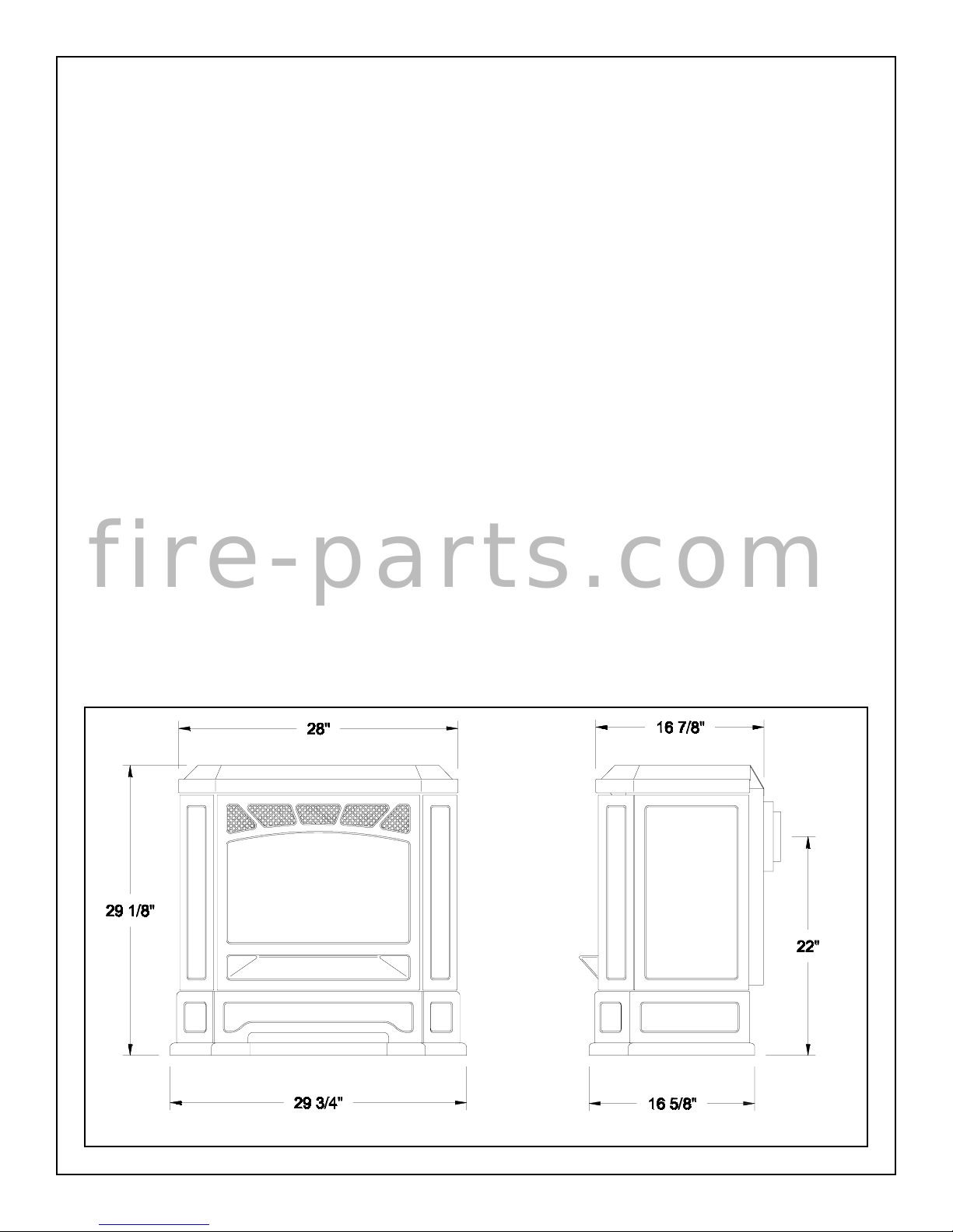
The minimum clearances from the appliance to combustibles are
shown on Fig. # 3. For purpose of servicing, a 10" right side clearance
(side with controls) is recommended. Adequate clearances around air
openings and combustion air supply are required.
* Alcove sidewall to appliance clearance is listed at 4 3/4". A 10"
clearance is recommended to center the appliance in a 48" minimum
wide Alcove.
Fig. # 3
Minimum Clearance
to Combustibles
Sidewall to Appliance 3 in. (76 mm)
Rearwall to Appliance 1 in. (25 mm)
Corner to Appliance 1 in. (25 mm)
* Alcove sidewall to Appliance 4 3/4 in. (121 mm)
Alcove minimum width 4' (1.2 m)
Alcove maximum height 5' (1.5 m)
f i r e - p a r t s . c o m
The Oxford Direct Vent Heater may be installed directly on a combustible floor. As the Oxford is supplied with its own built in metal base that
is wider and deeper than the appliance, no additional floor protection
panel is required.
FLOOR PROTECTION
**
ALCOVE HEIGHT - 5' MINIMUM
5
INSTALLATION PRECAUTIONS
The Oxford Heater installation and venting must conform with
local codes or, in the absence of local codes, with the current
Canadian Installation Code, CAN/CGA-B149 (in Canada) or the
current National Fuel Gas Code, ANSI Z223.1 (in the USA). Only
qualified (licensed or trained) personnel should install this product.
The Oxford may be converted to a Vented Room Heater with the
optional "B-Vent Adapter". Refer to the installation instructions
that are supplied with the kit for proper venting requirements.
Only qualified (licensed or trained) personnel should install this
product.
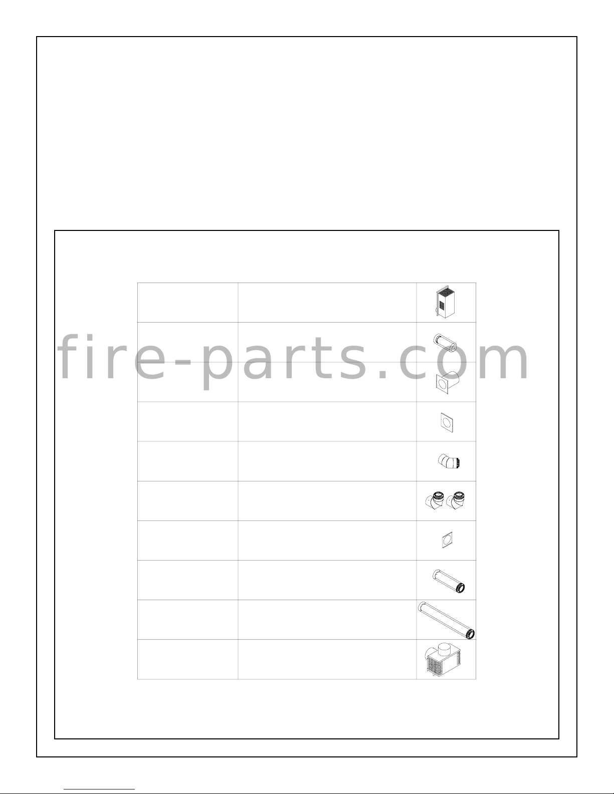
Fig # 4
PART DESCRIPTIONPART #
MFSD.RVT RISER VENT TERMINAL
MFSD.STRT 18 18" STARTER PIPE
VENT SYSTEM
Before starting installation of vent kits, the installer should read these
instructions to ensure that the proper vent system has been selected
for the installation.
Vent systems approved for use with the Oxford Direct Vent Heater are
shown in Figure 4. Approved vent systems components are labelled
for identification. NO OTHER VENTING SYSTEMS OR COMPO-
NENTS MAY BE USED.
Connections between each vent system component must be tightly
joined and sealed, and secured with sheet metal screws at each joint.
Consult your local Building Codes before beginning the installation.
CAUTION: UNDER NO CONDITION SHOULD COMBUSTIBLE
MATERIAL BE CLOSER THAN 1-INCH FROM THE VERTICAL
AND HORIZONTAL SECTIONS OF THIS VENT SYSTEM.
f i r e - p a r t s . c o m
MFSD.THIMB WALL THIMBLE SPACER
MFSD.1551_ _ TRIM COLLAR (SQUARE)
Specify Colour
MFSD.ELB 45 45° COAXIAL ELBOW
MFSD.ELB 90 90° COAXIAL ELBOW (2)
MFSD.WSS WALL SUPPORT SPACER
MFSD.CP24 24" COAXIAL PIPE
MFSD.CP48 48" COAXIAL PIPE
MFSD.BVADPT B-VENT ADAPTER
6

Fig. # 5
STRAIGHT THROUGH WALL INSTALLATION
f i r e - p a r t s . c o m
1) Determine the exact position of the gas stove so that the direct
vent pipe is centred (if possible) between two building framing
members. This will avoid any extra framing.
2) Carefully measure up 22-inches from the finished floor and mark
the centre of a 9-inch square or round hole. (See Figure # 6)
IMPORTANT: When locating this hole it should be noted that the
bottom of the vent terminal must be a MINIMUM of 12-inches
above grade, the top of the terminal must be a MINIMUM of 18inches below combustible material such as a deck or roof overhang and the side of the terminal must be a MINIMUM of 12-inches
away from an adjacent wall. (See Figure 10)
3) Cut a 9-inch square or round hole through the exterior wall of the
building.
4) Position the wall thimble spacer (WTS) from the inside through the
9-inch hole. (Figure 6). For walls less than 11-inches thick, the
thimble must be trimmed back flush with the exterior wall.
5) Attach the trim collar to the flanges of the wall thimble with the
screws provided.
6) The coaxial starter pipe (SK 18) may have to be cut to length
depending on the wall thickness and/or rear clearance of the
stove. Measure the wall thickness from the finished trim collar
surface to the exterior mounting surface for the vent terminal. Add
1/4 inch plus rear clearance to the wall thickness (i.e. rear
clearance of 1", add 1 1/4" , rear clearance of 3", add 3 1/4" to wall
thickness).
pipe over top of the collar up to the crimp-bead and attach with
three sheet metal screws. Seal the joint with high temperature
silicone. Next, slide the 7-inch outer pipe over the 5-inch pipe fully
and secure to the pipe collar with three sheet metal screws. Assure
that the vent pipe is level or has a 1/4" rise for every foot of run
towards the termination.
9) Slide the appliance into place, with vent pipe centred in wall passthrough. When the unit is properly installed, the 7-inch vent pipe
will project 3/4-inch past the outside wall surface and the 5-inch
inner pipe will extend 1-inch past that. Assure that the vent pipe is
level or has a 1/4" rise for every foot of run towards the termination.
10) Install vent terminal according to section VENT TERMINAL
INSTALLATION
Fig. # 6
7) Cut both pipes to this length. Do not cut off the crimp-bead off the
5-inch inner pipe.
8) The vent pipe must be attached to the collars of the gas stove with
the bead end towards the appliance. Slide the inner 5-inch flue
7
CORNER INSTALLATION
1) Determine the exact position of the gas stove, making sure the unit
will be set at 45° to the walls and the corner clearance will not be
less then 1-inch. The vent pipe should be centred (if possible)
between two building members. This will avoid any extra framing.
2) Once the desired location is found, carefully measure up 22inches from the finished floor and make a mark. Next, measure 7inches plus the actual corner clearance of the appliance over from
the corner of the room and make a mark. (i.e. corner clearance of
1", measure 8"; corner clearance of 3", measure 10")
IMPORTANT: When locating this hole it should be noted that the
bottom of the vent terminal must be a MINIMUM of 12-inches
above grade, the top of the terminal must be a MINIMUM of 18inches below combustible material such as a deck or roof overhang and the side of the terminal must be a MINIMUM of 12-inches
away from an adjacent wall (See Figure 10).
3) Cut a 9-inch square or round hole through the exterior wall of the
building.
4) Position the wall thimble spacer (WTS) from the inside through the
9-inch hole. (Figure 6). For walls less than 11-inches thick, the
thimble must be trimmed back flush with the exterior wall.
5) Attach the trim collar to the flanges of the wall thimble with the
screws provided.
6) Attach the coaxial 45° elbow (LB 45) to the unit. Slide the 5-inch
inner elbow pipe 1-inch over top of the collar and secure with three
sheet metal screws. Seal the joint with high temperature silicone.
f i r e - p a r t s . c o m
Next, slide the outer elbow pipe over the smaller elbow and secure
to the pipe collar with three sheet metal screws.
7) The coaxial starter pipe (SK 18) may have to be cut to length
depending on the wall thickness and/or corner clearance of the
stove. Measure the wall thickness from the finished trim collar
surface to the exterior mounting surface for the vent terminal. Add
3 3/4-inches plus corner clearance to the wall thickness. (i.e.
corner clearance of 1", add 4 3/4" , corner clearance of 3", add 6
3/4" to wall thickness)
Fig. # 7
8) Cut both pipes to this length.
9) Slide the inner 5-inch flue pipe over top of the crimped end of elbow
and attach with three sheet metal screws. Seal the joint with high
temperature silicone. Next, slide the 7-inch outer elbow pipe over
the 5-inch elbow fully and secure to the elbow with three sheet
metal screws. Assure that the vent pipe is level or has a 1/4" rise
for every foot of run towards the termination.
10) Slide the appliance into place making sure vent pipe is centred in
wall pass-through. When the unit is properly installed, the 7-inch
vent pipe will project 3/4-inch past the outside wall surface and the
5-inch inner pipe will extend 1-inch past that.
11) Install vent terminal according to section VENT TERMINAL IN-
STALLATION
8
 Loading...