

Pacific energy The Esteem Installation And Operating Instructions Manual
IMPORTANT:
THESE INSTRUCTIONS ARE TO
REMAIN WITH THE
HOMEOWNER
FOR YOUR SAFETY
WARNING: If the information in this
manual is not followed exactly, a re or
explosion may result causing property
damage, personal injury or loss of life.
-- Do not store or use gasoline or other
ammable vapors and liquids in the vicinity
of this or any other appliance.
The
-- WHAT TO DO IF YOU SMELL GAS
• Do not try to light any appliance.
• Do not touch any electrical switch; do
not use any phone in your building.
• Immediately call your gas supplier
f i r e - p a r t s . c o m
from a neighbour’s phone. Follow
the gas supplier’s instructions.
• If you cannot reach your gas supplier,
call the re department.
-- Installation and service must be
performed by a quali ed installer, service
agency or the gas supplier.
This appliance may be installed in
an aftermarket permanently located,
manufactured (mobile) home, where not
prohibited by local codes.
Esteem
SERIES C
DIRECT VENT FIREPLACE
ESMC.BODYAM
This appliance is only for use with the type
of gas indicated on the rating plate. This
appliance is not convertible for use with
other gases, unless a certi ed kit is used.
040706-44 ESTEEM_CM 5056.411.C1
INSTALLATION
AND OPERATING
INSTRUCTIONS
Contents
CAUTION ............................................................................................................................ 3
SAFETY ............................................................................................................................... 3
MAINTENANCE .................................................................................................................. 3
IMPORTANT NOTE FOR THE COMMONWEALTH OF MASSACHUSETTS: .................. 4
TOP STANDOFFS .............................................................................................................. 6
INSTALLATION REQUIREMENTS .................................................................................... 6
FRAMING ............................................................................................................................ 6
FRAMING FOR SCREEN FRONT ...................................................................................... 7
PROPANE CONVERSION .................................................................................................. 8
TOP OR REAR VENT ....................................................................................................... 12
VENT ADAPTER INSTALLATION ................................................................................... 12
VENTING ........................................................................................................................... 12
VENT SYSTEM RESTRICTOR ADJUSTMENT ............................................................... 16
FLEX VENT CONNECTION .............................................................................................. 17
VENT EXTENSION ........................................................................................................... 17
VENT TERMINAL INSTALLATION .................................................................................. 18
ROOF VENT TERMINAL INSTALLATION ....................................................................... 19
OPTIONAL VENTING ....................................................................................................... 21
MANUFACTURED (MOBILE) HOME ............................................................................... 22
OPTIONAL SNORKEL VENT TERMINAL ....................................................................... 22
GAS SUPPLY .................................................................................................................... 23
OPTIONAL BRICK PANELS INSTALLATION ................................................................. 24
BURNER REMOVAL ........................................................................................................ 24
LOG SET ASSEMBLY ...................................................................................................... 25
OPTIONAL BLOWER ....................................................................................................... 27
LIGHTING INSTRUCTIONS .............................................................................................. 29
REMOTE OPERATION ..................................................................................................... 30
f i r e - p a r t s . c o m
CENTER OF TOP
FLUE OUTLET
FIRST FIRE ....................................................................................................................... 31
MANUAL OPERATION ..................................................................................................... 31
FLAME ADJUSTMENT ..................................................................................................... 31
REPLACEMENT PARTS .................................................................................................. 32
BURNER REPLACEMENT PARTS .................................................................................. 33
APPENDIX A .....................................................................................................................34
Optional Front Facing Trim ..................................................................................... 35
Optional Remote Control Installation ..................................................................... 37
Optional Blower Kit .................................................................................................. 38
Wall Termination Kit ................................................................................................. 39
5' Vent Pipe Kit ......................................................................................................... 40
10' Vent Pipe Kit ....................................................................................................... 41
Roof Termination Kit ................................................................................................ 42
Safety Label .............................................................................................................. 43
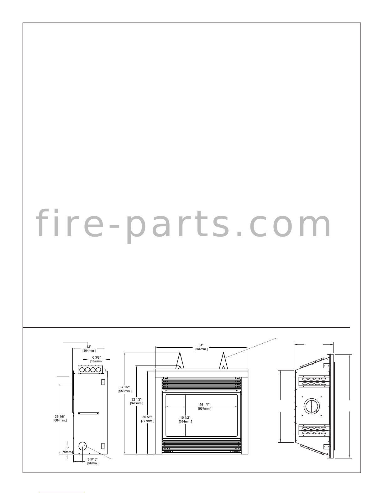
EXTENDED
TOP STANDOFFS
12 3/4”
[324mm]
CENTER OF REAR
FLUE OUTLET
GAS INLET
ACCESS HOLE
2 ESTEEM_CM 040706-44
23 1/2”
[597mm]
34”
[864mm]
CAUTION
MAINTENANCE
FOR YOUR SAFETY - Do not install or operate your Paci c Energy
replace without rst reading and understanding this manual. Any
installation or operational deviation from the following instructions
voids the Paci c Energy Warranty and may prove hazardous.
This appliance and its individual shutoff valve must be disconnected
from gas supply piping system during any pressure testing of that
system at test pressures in excess of 1/2 psig (3.5 kPa).
This appliance must be isolated from the gas supply piping system
by closing its individual manual shutoff valve during any pressure
testing of the gas supply piping system at test pressures equal to or
less than 1/2 psig (3.5 kPa).
Note: When lit for the rst time, the appliance will emit a slight odour
for a couple of hours. This is due to the curing of paints, sealants
and lubricants used in the manufacturing process. This condition is
temporary. Open doors and windows to ventilate area. Smoke and
fumes caused by the curing process may cause discomfort to some
individuals.
SAFETY
Due to high temperatures, this gas appliance should be located
out of traf c and away from furniture and draperies.
Children and adults should be alerted to the hazards of high
surface temperatures and should stay away to avoid burns or
clothing ignition.
f i r e - p a r t s . c o m
Young children should be carefully supervised when they
are in the same room as the appliance.
Clothing or other ammable material should not be placed
on or near the appliance.
Any grill, panel or door removed for servicing the unit must
be replaced prior to operating. Failure to do so may create a
hazardous condition.
Installation and repair should be done by a quali ed service
person. The appliance should be inspected before use and at
least annually by a professional service person. More frequent
cleaning may be required due to excessive lint from carpeting,
bedding material, etc. It is imperative that control compartments,
burners and circulating air passageways of the appliance be
kept clean.
It is Paci c Energy’s policy that no responsibility is assumed
by the Company or by any of its employees or representatives
for any damages caused by an inoperable, inadequate, or unsafe
condition which is the result, either directly or indirectly, of any
improper operation or installation procedures.
Caution: Turn off gas and electrical power supply and allow ample
time for unit to cool before servicing appliance. It is recommended
that this appliance and venting should be inspected at least once a
year by a quali ed service person.
Do not use this heater if any part has been under water. Immediately
call a quali ed service technician to inspect the heater and to replace
any part of the control system and any gas control which has been
under water.
Glass Panel:
Warning: Do not operate appliance with glass panel removed,
cracked or broken. Replacement of the glass panel should be done
by a licensed or quali ed service person.
Do not strike or otherwise impact the glass in anyway that may cause it
to break. If the glass becomes cracked or broken, it must be replaced
before using the replace. Replacement glass can be obtained from
your nearest Paci c Energy dealer. The size required is 17 1/8" x
28 1/4" x 5mm. Use ceramic glass only. Do not substitute with
any other type.
To remove broken glass, fold down the front bottom louver to access
the window latches.
Disengage the over-center latches by pulling each lever down and
forward. Grasp the sides of the frame and swing the bottom out to
clear. Lift up and forward to disengage from the top. Remove all
particles of glass. Be careful as they are very sharp. Install new glass
complete with gasket. Replace frame and screws.
Annual Inspection:
a) Clean louvers and air passage ways of excessive lint buildup
from carpeting, bedding material, etc. The ow of combustion and
ventilation air must not be obstructed.
b) Remove glass panel and log set. Inspect logs and burner assembly
for lint and soot buildup. If excessive buildup of soot is present,
have a quali ed service person inspect and adjust unit for proper
combustion. Clean logs and burner with a vacuum cleaner, paying
close attention to burner ports.
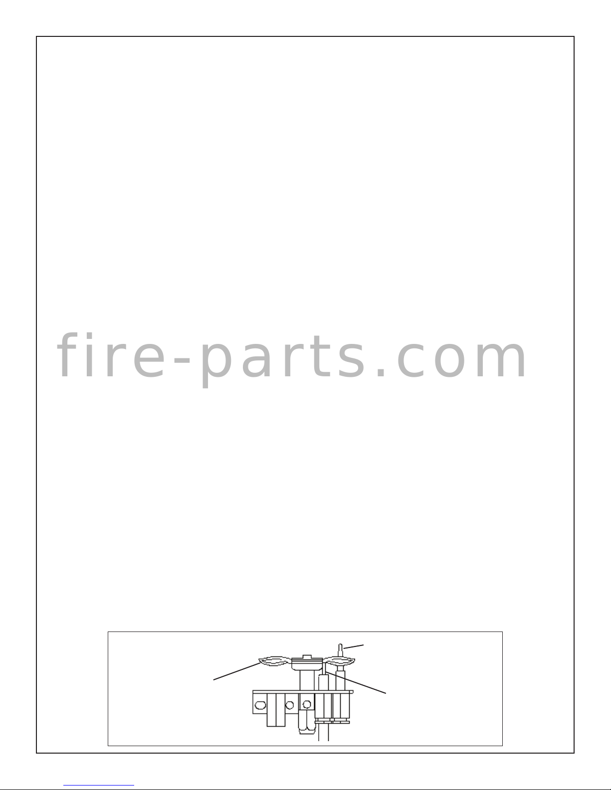
c) Check the pilot system for proper ame size and operation. (See
Fig. #1) Clean pilot free of lint and dust.
d) Check that the vent pipe and vent terminal are open and free from
blockage or debris. If the venting is disassembled for cleaning, it must
be properly assembled and resealed. Refer to VENTING section for
proper procedure.
e) Check glass panel gasket, replace if necessary. It is important
that the glass seal be maintained in good condition
Note: The appliance area must be kept clear and free from combustible
materials, gasoline and other ammable vapours and liquids.
Periodically:
a) Viewing glass may be cleaned with replace glass cleaner.
b) Exterior nish may be cleaned with mild soap and water.
Caution:
- do not use abrasive cleaners on glass or any other part of the
replace.
- do not clean glass when hot.
Fig. # 1
PILOT FLAME
040706-44 ESTEEM_CM 3
THERMOCOUPLE
ELECTRODE
IMPORTANT NOTE FOR THE COMMONWEALTH OF MASSACHUSETTS:
From Massachusetts Rules and Regulations 248 CMR 5.08:
(a) For all side wall horizontally vented gas fuelled equipment installed in every dwelling, building or structure used in
whole or in part for residential purposes, including those owned or operated by the Commonwealth and where the side wall
exhaust vent termination is less than seven (7) feet above nished grade in the area of the venting, including but not limited to
decks and porches, the following requirements shall be satis ed.
1. INSTALLATION OF CARBON MONOXIDE DETECTORS. At the time of installation of the side wall horizontal vented
gas fuelled equipment, the installing plumber or gas tter shall observe that a hard wired carbon monoxide detector with an
alarm and battery back-up is installed on the oor level where the gas equipment is to be installed, in addition, the installing
plumber or gas tter shall observe that a battery operated or hard-wired carbon monoxide detector with an alarm is installed on
each additional level of the dwelling, building or structure served by the side wall horizontal vented gas fuelled equipment. It
shall be the responsibility of the property owner to secure the services of quali ed licensed professionals for the installation of
hard-wired carbon monoxide detectors.
a. In the event that the side wall horizontally vented gas fuelled equipment is installed in a crawl space or an attic, the
hard-wired carbon monoxide detector with alarm and battery back-up may be installed on the next adjacent oor level.
b. In the event that the requirements of this subdivision cannot be met at the time of completion of installation, the owner
shall have a period of thirty (30) days to comply with the above requirements; provided, however, that during said thirty (30)
day period, a battery operated carbon monoxide detector with an alarm shall be installed.
2. APPROVED CARBON MONOXIDE DETECTORS. Each carbon monoxide detector as required in accordance with
the above provisions shall comply with NFPA 720 and be ANSI/UL 2034 listed as IAS certi ed.
3. SIGNAGE. A metal or plastic identi cation plate shall be permanently mounted to the exterior of the building at a
minimum height of eight (8) feet above grade directly in line with the exhaust vent terminal for the horizontally vented gas
f i r e - p a r t s . c o m
fuelled heating appliance or equipment. The sign shall read, in print size no less than one-half (1/2) inch in size, “GAS VENT
DIRECTLY BELOW. KEEP CLEAR OF ALL OBSTRUCTIONS”.
4. INSPECTION. The state or local gas inspector of the side wall horizontally vented gas fuelled equipment shall not
approve the installation unless, upon inspection, the inspector observes carbon monoxide detectors and signage installed in
accordance with the provisions of 248 CMR 5.089(2)(a) 1 through 4.
(b) EXEMPTIONS. The following equipment is exempt from 248 CMR 5.089(2)(a) 1 through 4.
1. The equipment listed in Chapter 10 entitled “Equipment Not Required To Be Vented” in the most current edition of
NFPA 54 as adopted by the Board; and
2. Product Approved side wall horizontal vented gas fuelled equipment installed in a room or structure separate from the
dwelling, building or structure used in whole or in part for residential purposes.
(c) MANUFACTURER REQUIREMENTS – GAS EQUIPMENT VENTING SYSTEM PROVIDED. When the
manufacturer of Product Approved side wall horizontally vented gas equipment provides a venting system design or venting
system components with the equipment, the instructions provided by the manufacturer for installation of the equipment and the
venting system shall include:
1. Detailed instructions for the installation of the venting system design or the venting system components; and
2. A complete parts list for the venting system design or venting system.
(d) MANUFACTURER REQUIREMENTS – GAS EQUIPMENT VENTING SYSTEM NOT PROVIDED. When the
manufacturer of a Product Approved side wall horizontally vented gas fuelled equipment does not provide the parts for venting
the fuel gases, but identi es “special venting systems”, the following requirements shall be satis ed by the manufacturer.
1. The referenced “special venting system” instructions shall be included with the appliance or equipment installation
instructions; and
2. The “special venting systems” shall be Product Approved by the Board, and the instructions for that system shall
include a parts list and detailed installation instructions.
(e) A copy of all installation instructions for all Product Approved side wall horizontally vented gas fuelled equipment, all
venting instructions, all parts lists for venting instructions, and/or all venting design instructions shall remain with the appliance
or equipment at the completion of the installation.
4 ESTEEM_CM 040706-44
Minimum Clearances to Combustibles:
Fig. # 2
**
Side standoffs ...................... 0 in. (0 mm)
Back standoffs ..................... 0 in. (0 mm)
Top standoffs ....................... 0 in. (0 mm)
Adjacent sidewall ................. 0 in. (0 mm)
Ceiling to appliance ........... 24 in. (610 mm)
Mantel to appliance ..........See Figure # 3 and 3a
Maximum mantel extension ..........
See Figure # 3 and 3a
Mantel support ..................... 0 in. (0 mm)
Paci c Energy Vent pipe ..... 1 in. (25 mm)
Simpson Dura-Vent
GS pipe .................... 1-3/4 in. (45 mm)
Security Chimneys
Secure Vent pipe ...... 1-3/4 in. (45 mm)
CEILING
24" [610mm.]
30 5/8" [778 mm.]
ADJACENT
MANTEL
WALL OR
MANTEL
SUPPORT
*
0" [0mm.]
* Mantel to appliance .................See Figure # 3 and 3a
** Maximum mantel extension .....See Figure # 3 and 3a
f i r e - p a r t s . c o m
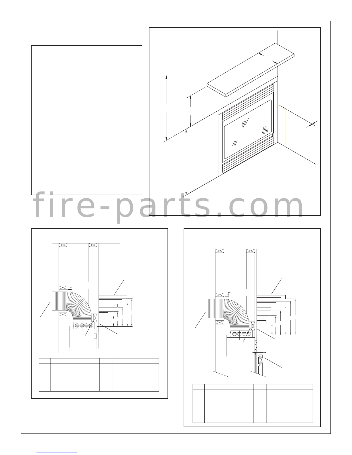
Fig. # 3
MANTEL CLEARANCES
Fig. # 3a
MANTEL CLEARANCES
WITH OPTIONAL BAY FRONT
COMBUSTIBLE
MANTEL
1" [25mm.]
N
M
L
K
J
TOP OR
REAR
VENTING
HEADER
Ref. Mantel Width Ref. Clearance
J 4" (102 mm) A 4 1/2" (114 mm)
K 6" (152 mm) B 6 3/8" (162 mm)
L 8" (203 mm) C 8 1/4" (210 mm)
M 10" (254 mm) D 10 1/8" (257 mm)
N 12" (305 mm) E 12" (305 mm)
A
E
D
C
B
FINISHED WALL
COMBUSTIBLE
MANTEL
1" [25mm.]
2
1
TOP OR
REAR
VENTING
HEADER
Ref. Mantel Width Ref. Clearance
1 4" (102 mm) A 4 1/2" (114 mm)
2 5" (127 mm) B 8" (203 mm)
3 6" (152 mm) C 10" (254 mm)
4 8" (203 mm) D 12" (305 mm)
5 10" (254 mm) E 14" (356 mm)
6 12" (305 mm) F 15" (381 mm)
6
5
4
3
D
C
B
A
FINISHED WALL
BAY FRONT
F
E
040706-44 ESTEEM_CM 5
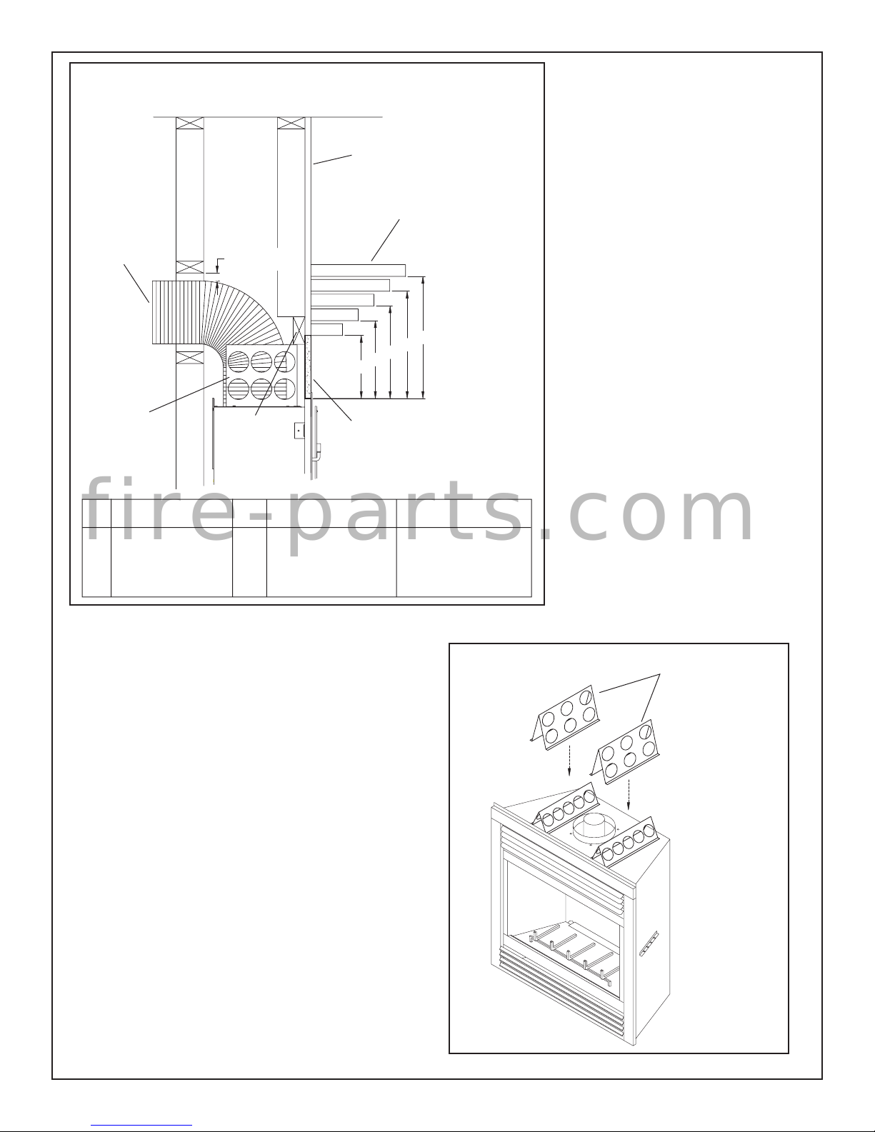
Fig. # 3c
TOP OR
REAR
VENTING
TOP
STANDOFF
1" [25mm.]
HEADER
MANTEL CLEARANCES
WITH OPTIONAL SCREEN FRONT
FINISHED WALL
COMBUSTIBLE
MANTEL
N
M
L
K
J
B
A
8" HIGH
CEMENT BOARD
MANDATORY WITH
SCREEN DOORS
E
D
C
TOP STANDOFFS
The Esteem Fireplace is shipped with the short
top standoffs in place and the extended top
standoffs loose. If the Optional Screen Door
is to be installed, the short standoffs must be
replaced with the extended standoffs.
1) Remove the four screws attaching each top
standoff in place and remove standoffs.
2) Position extended top standoffs in same
place and attach with screws.
INSTALLATION REQUIREMENTS
The Esteem Fireplace installation and
venting must conform to the current CAN/
CGA-B149 installation code (in Canada) or the
current National Fuel Gas Code, ANSI Z223.1
(in the USA), and approved per local codes.
Only quali ed (licensed or trained) personnel
should install this product.
Ref. Mantel Width Ref. Clearance Clearance
Top Edge of Screen Top Edge of Unit
J 4" (102 mm) A 7 1/4" (184 mm) 8" (203 mm)
f i r e - p a r t s . c o m
K 6" (152 mm) B 9 1/8" (232 mm) 9 7/8" (251 mm)
L 8" (203 mm) C 11" (280 mm) 11 3/4" (298 mm)
M 10" (254 mm) D 12 7/8" (327 mm) 13 5/8" (346 mm)
N 12" (305 mm) E 14 3/4" (375 mm) 15 1/2" (394 mm)
The Esteem Fireplace is designed to be framed
at zero clearance to combustible material with
conventional lumber. Ensure framing dimensions
are maintained during construction.
FRAMING
In planning the installation for the Esteem Fireplace, it is necessary
to determine where the unit is to be installed, location of vent system
and where gas supply piping may be plumbed. Various installations
are possible, such as, into an existing wall, a corner, a built-in wall or a
wall projection (see Fig. #7). Due to high temperatures, do not locate
this appliance in areas of high traf c or near furniture or draperies.
Once the nal location has been determined, frame a minimum
opening of 34-1/4 inches wide, 32-3/4 inches high and 12-1/4 inches
deep with conventional 2 x 4 lumber (see Fig. #5 and #6). It may
be preferred to frame the replace after it is positioned and the vent
system is installed. Heavier construction may be required for some
installations, consult local building codes for speci c requirements.
Ensure framing dimensions are maintained during construction.
Bend out the two nailing tabs on each side and secure the replace
to framing with screws or nails (see Fig. #4). The tabs will allow for
a nishing wall up to 3/4 inch thick, if thicker, unit must be spaced
outwards accordingly. The wall may be nished up to the replace
facing with combustible material (see Fig. #3).
Fig. # 3d
Extended
Top Standoffs
The minimum clearances from the appliance to combustible surfaces
are shown on Fig. #2 and 3. Adequate clearances around air openings and combustion air supplies are required.
Chase Insulation: When installing this replace against a non-insulated exterior wall or chase, it is recommended that the outer walls
be insulated to same degree as other exterior walls. Do not place
replace directly against the insulation. Cover the insulation and
plastic vapour barrier with a solid surface, such as drywall (sheetrock).
Consult local codes.
6 ESTEEM_CM 040706-44
Hearth Extension: While a hearth extension may be desirable for
aesthetic reasons, it is not required for this replace. If one is desired,
the hearth extension may be up to 3/8 inch thick, if thicker, the replace
must be spaced up accordingly.
Fig. # 4
NAILING
TABS
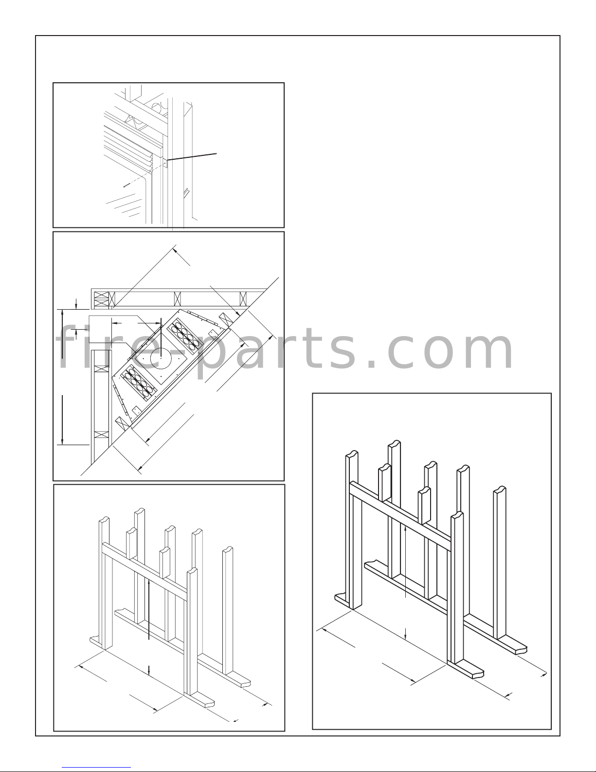
Fig. # 5
CORNER FRAMING
DIMENSIONS
23 1/4"
* 5"
12"
FRAMING FOR SCREEN FRONT
In planning the installation for the Esteem Fireplace, it is necessary
to determine where the unit is to be installed, location of vent system
and where gas supply piping may be plumbed. Various installations
are possible, such as, into an existing wall, a corner, a built-in wall or a
wall projection. Due to high temperatures, do not locate this replace
in areas of high traf c or near furniture or draperies.
Once the nal location has been determined, frame a minimum opening
of 34-1/4 inches wide, 37-3/4 inches high and 12-1/4 inches deep
with conventional 2 x 4 lumber (see Fig. #6b). It may be preferred
to frame the replace after it is positioned and the vent system is
installed. Heavier construction may be required for some installations,
consult local building codes for speci c requirements. Ensure framing
dimensions are maintained during construction.
Bend out the two nailing tabs on each side and secure the replace
to framing with screws or nails. The tabs will allow for a nishing
wall up to 3/4 inch thick, if thicker, the unit must be spaced outwards
accordingly.
Due to higher temperatures with the Screen Door, concrete board (or
other non-combustible material) must be used to sheet in the front of
the replace. The concrete board must extend 8" above and to the full
width of the unit. (see Fig. #6c). Standard sheetrock (drywall) may be
used beyond this and up to the sides of the replace.
The minimum clearances from the appliance to combustible surfaces
are shown on Fig. # 2. Adequate clearances around air openings and
combustion air supplies are required.
Refer to the replace installation manual supplied with the unit for
additional requirements.
f i r e - p a r t s . c o m
32 15/16"
Fig. # 6a
34 1/4"
46 9/16"
* Paci c Energy Flex
Pipe requires 5 1/4"
FRAMING DIMENSIONS
Fig. # 6b
FRAMING DIMENSIONS
OPTIONAL SCREEN FRONT
37 3/4"
32 3/4"
34 1/4"
040706-44 ESTEEM_CM 7
34 1/4"
12 1/4"
12 1/4"
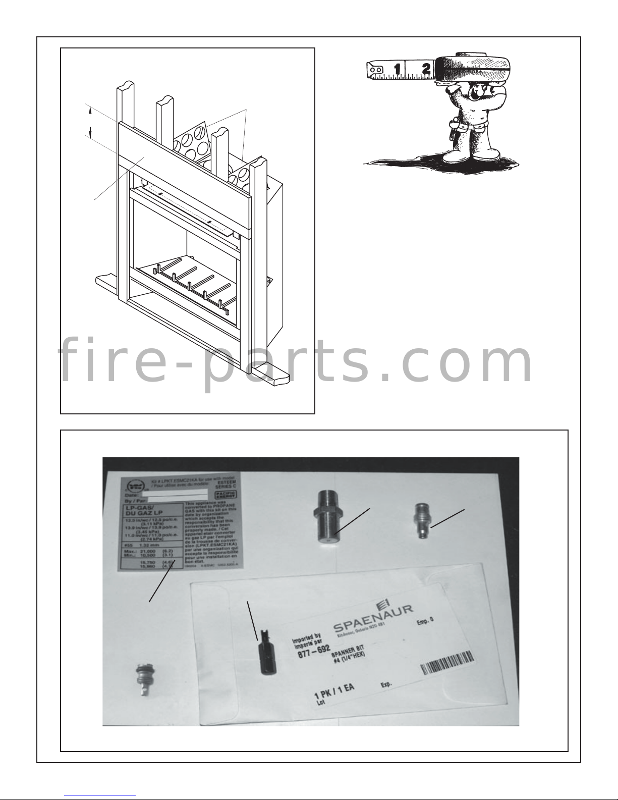
Fig. # 6c
8"
CONCRETE BOARD DETAIL
Extended
Top Standoffs
Concrete
Board
Using the components shown in Fig. #7, the Esteem Direct Vent
Fireplace can be converted to Propane Gas as follows:
PROPANE CONVERSION
Burner Ori ce
1) Ensure the burner, pilot and gas supply are turned off and
the appliance has cooled.
2) If the logs are installed take note of their positions and carefully remove them.
3) Remove the grate assembly by removing the two screws
located at the rebox rear right and left corners. (See Fig.
f i r e - p a r t s . c o m
Concrete board (or other non-combustible material)
must extend 8" above and full width of the unit.
Fig. # 7
PARTS NEEDED FOR LP CONVERSION:
#8)
4) Remove the brick panels if installed.
Burner Orifice
(Marked 55)
(5021.35)
Pilot Orifice
(Marked #35)
(5009.169)
"Snake Eye" Screwdriver Bit
(5038.5)
Conversion Label
(5052.5205)
Minimum Rate Screw
(5007.002)
8 ESTEEM_CM 040706-44
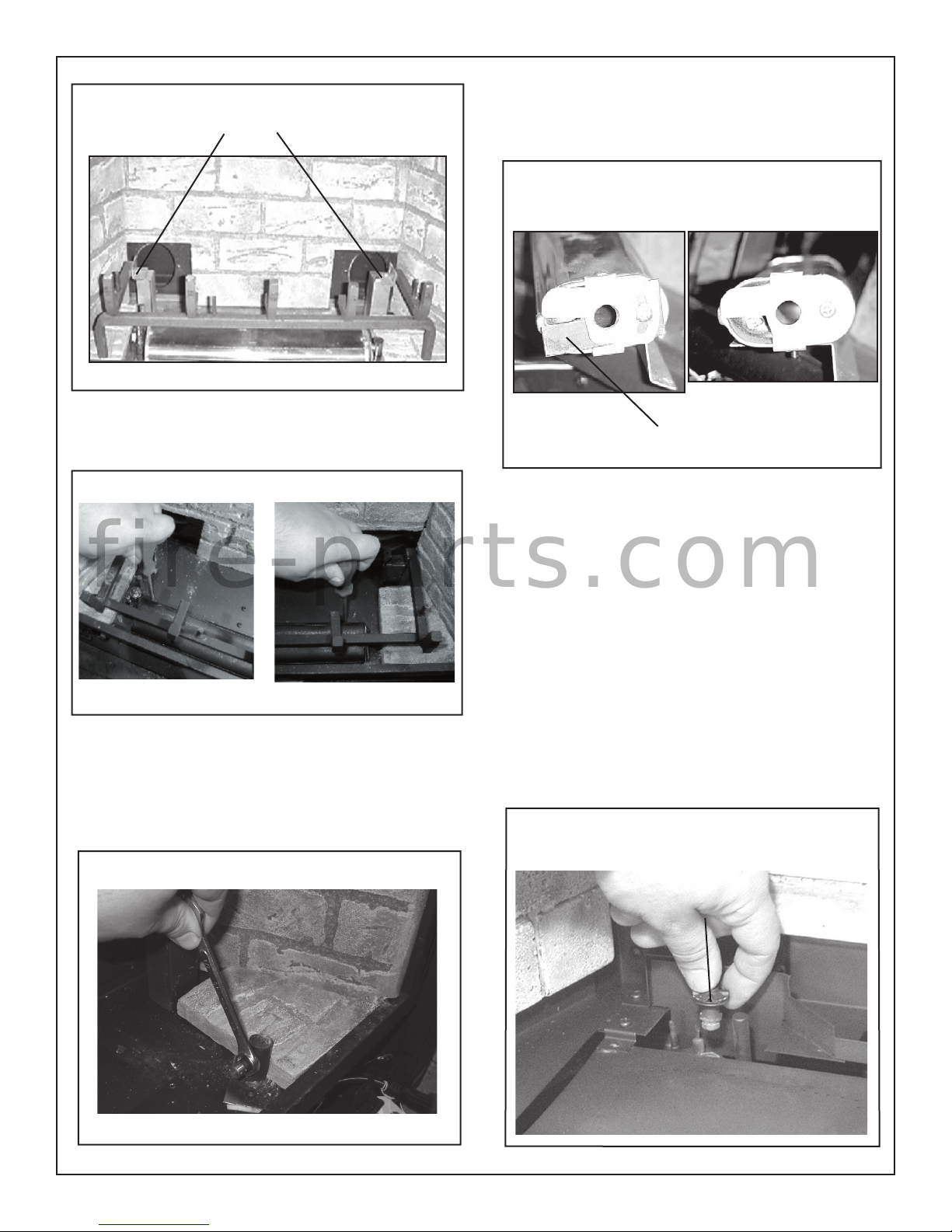
Fig. # 8
Grate Assembly
Attachment Points
8) Remove xed air shutter by removing screw. Reassemble with
adjustable air shutter only. (Fig. #11)
Fig. # 11
Natural Gas Propane
5) Remove the two screws holding the burner bracket in place. (Fig.
#9)
Fig. # 9
f i r e - p a r t s . c o m
6) Remove the burner by sliding it to the left and up.
7) Using a 1/2” wrench, remove the natural gas ori ce, (marked #45).
Apply a small amount of pipe joint compound to the threads of the
propane ori ce (marked #55) to ensure a good seal, and install it.
(Fig. #10)
Fig. #10
Remove This Non-Adjustable Shutter For LP
Pilot Ori ce
1) Pull the pilot hood assembly up and off to gain access to the pilot
ori ce. (Fig. #12)
2) Remove the ori ce with a 5/32” (4 mm) hex key and replace it
with the one supplied with the kit. (Fig. #13) Propane pilot ori ce
is marked #35.
3) Reinstall the pilot hood assembly.
4) Reinstall the burner and secure.
Fig. #12
040706-44 ESTEEM_CM 9
Pilot Hood
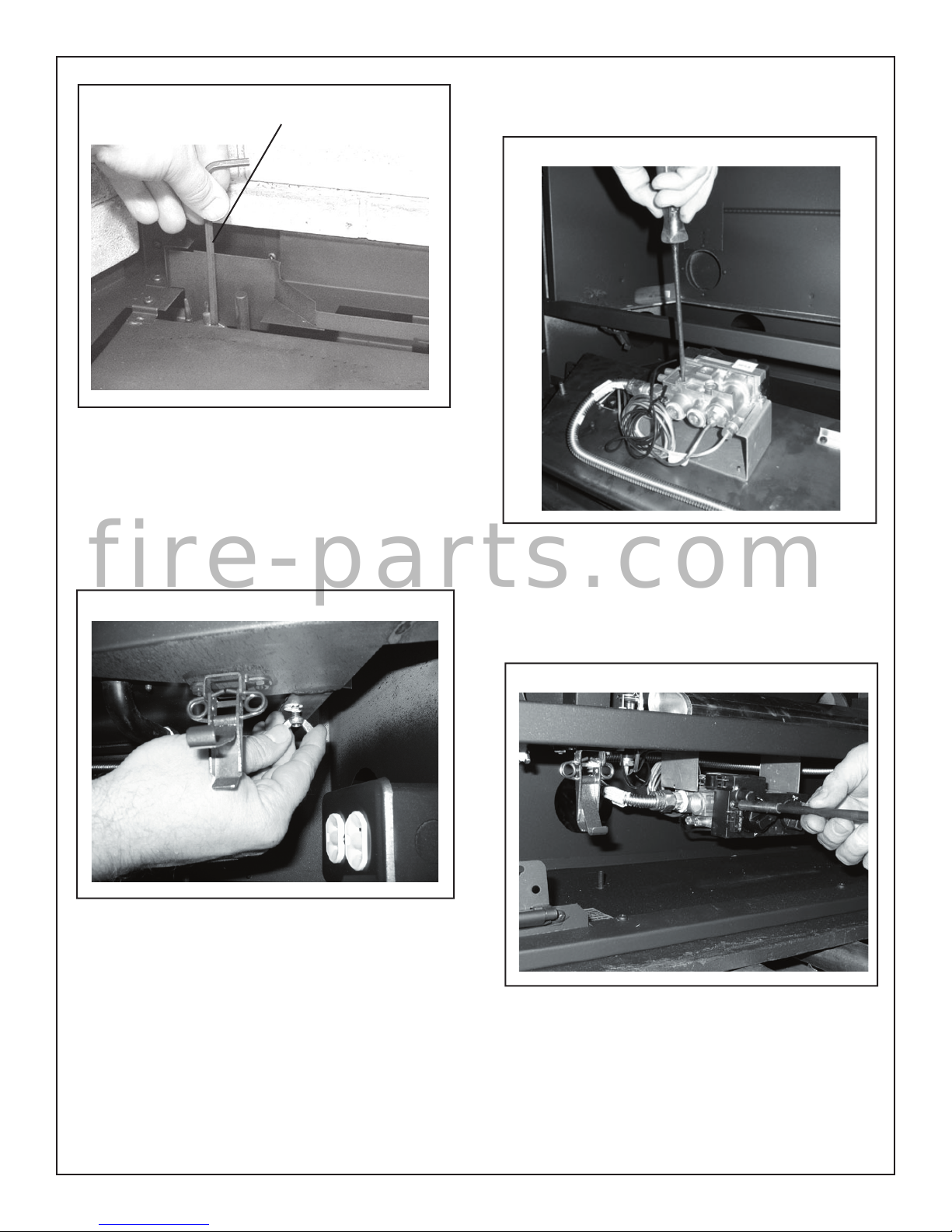
Fig. # 13
Valve Conversion
1) Remove gas the supply line to the burner.
2) Remove the two wing nuts securing the burner tray to the
replace and remove from the replace. (Fig. #14)
Hex Key
4) Re-attach the burner tray to replace using the two wing nuts,
and reconnect the gas supply.
Fig. # 15
f i r e - p a r t s . c o m
Fig. # 14
3) Remove the minimum rate screw from the bottom of the valve
and replace with the propane screw supplied. (Fig. #15)
5) Using the "snake eye" screwdriver bit provided, remove the
screw securing the front cover to the valve and remove the
cover. (Fig. #16)
Fig. # 16
10 ESTEEM_CM 040706-44
6) Loosen the rear pressure tapping screw on the valve and
attach a manometer. Note the pressure tapping screw cannot
be removed. (Fig. #17) The rearmost pressure tap reads
manifold pressure, while the frontmost pressure tap reads inlet
pressure.

LP-GAS/
DU GAZ LP
12.5 in/wc / 12.5 po/c.e.
(3.11 kPa)
13.9 in/wc / 13.9 po/c.e.
(3.45 kPa)
11.0 in/wc / 11.0 po/c.e.
(2.74 kPa)
#55 1.32 mm
Max.: 21,000 (6.2)
Min.: 10,500 (3.1)
15,750 (4.6)
15,960 (4.7)
This appliance was
converted to PROPANE
GAS with this kit on this
date by organization
which accepts the
responsibility that this
conversion has been
properly made. / Cet
appariel etair converter
au gaz LP par l'emploi
de la trousse de conversion (LPKT.ESMC21KA)
par une organization qui
accepte la responsibilité
pour une installation en
bon état.
Date: ______________________
By / Par: ___________________
Kit # LPKT.ESMC21KA for use with model
/ Pour utilise avec du modèle: ESTEEM
SERIES C
180204 6-ESMC 5052.5205.A
Fig. # 17
7) Light the replace and ensure that the "On / Off" knob and the
"Flame control" knob are rotated fully anti-clockwise to the "On"
position. (Fig. #18)
Fig. # 18
FLAME CONTROL
ON / OFF
9) Reassemble the valve cover and all other components. Note:
Ensure that the pressure tapping screw is tight.
LIGHT THE APPLIANCE AND THOROUGHLY LEAK-TEST ALL
CONNECTIONS. VERIFY PROPER BURNER IGNITION AND
OPERATION.
Conversion Label
In the white area on the conversion label, ll in the date and
the name of the person who performed the conversion. Peel off
the protective backing and apply the conversion label directly
over the gas pressure speci cations on the rating label.
f i r e - p a r t s . c o m
8) Adjust the pressure regulator by rotating the pressure adjustment screw clockwise until the correct pressure is read on the
manometer. (11" w.c.) (Fig. #19)
Fig. # 19
040706-44 ESTEEM_CM 11
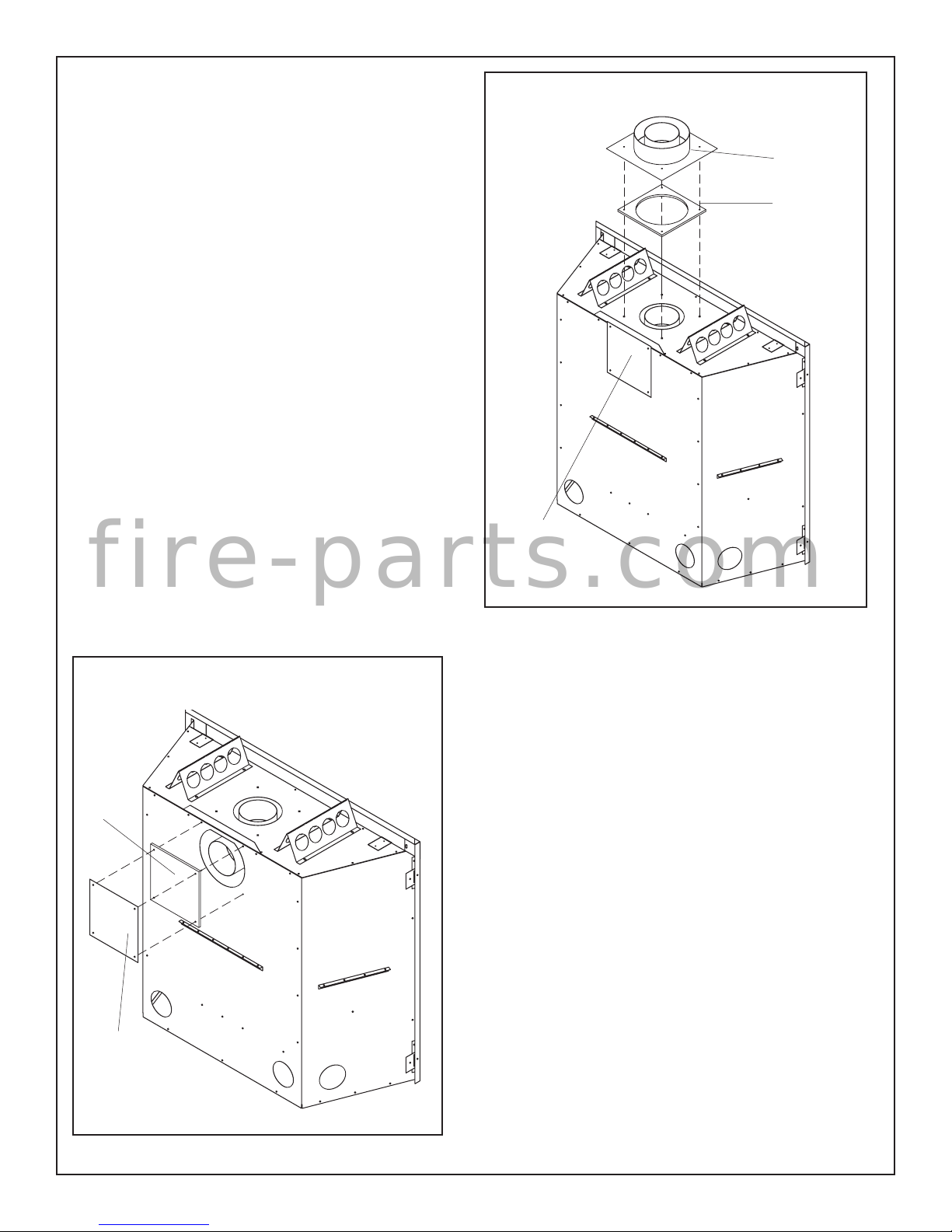
TOP OR REAR VENT
Caution: The unused vent outlet must be blocked with the vent
cover plate and gasket.
The Esteem is capable of top or rear vent applications. The replace
is factory set for top vent application.
If you choose to use this appliance in a rear vent application you
must re- install the vent cover plate and gasket on the top vent (see
Fig. #22).
Vent cover plate removal and installation.
1) Remove the four # 8 x 1/2" sheet metal screws that attach the
vent cover plate to the rear of the appliance. Remove the cover
plate and gasket. Be careful not to damage the gasket. (see Fig.
#20)
2) Remove the four screws around the top vent outlet.
3) Place the gasket and vent cover plate over the top vent outlet.
4) Secure in place with screws previously removed. (see Fig.
#22)
Fig. # 21
VENT ADAPTER INSTALLATION
The Esteem replace easily adapts to use either the Paci c Energy
Flex Vent, Simpson Dura-Vent GS or Security Secure Vent venting
system. Each system requires a speci c vent adapter. Paci c Flex
Vent adapter (ENCD.PEADPT) or Dura-Vent / Secure Vent adapter
(ENCD.DVADPT).
f i r e - p a r t s . c o m
Supplied with each adapter is a ceramic gasket (# 2761.0) that must
be used.
Vent
Cover Plate
Vent
Adapter
Adapter
Gasket
Fig. # 20
Gasket
Vent
Cover Plate
Installation:
The adapter 4" pipe must be sealed to the replace 4" vent outlet. Failure
to seal this joint may cause the replace to not operate properly.
1) Apply a bead of black sealant (supplied with the replace) to inside
of the ared end of adapter.
2) Place the gasket and vent adapter over the vent outlet and align
with attachment holes.
3) Secure in place with four #8 x 1/2” sheet metal screws previously
removed (see Fig. #21).
VENTING
Ensure the proper venting con guration is selected before installing venting for this unit.
Use only Paci c Energy vent kits #:
GASC.WALKIT - Wall Termination Kit
ESTD.ROTKIT - Roof Termination Kit
ESTD.VP05 - 5' Vent Pipe Kit
ESTD.VP10 - 10' TOP OR REAR VENT
Standard roof ashing or ashing listed below may be used.
ESTD.ROFLAT - Flat Roof Flashing ( at roof)
ESTD.ROADJ - Adjustable Roof Flashing (1/12 to 7/12 pitch)
ESTD.ROSTP - Steep Roof Flashing (8/12 to 12/12 pitch)
12 ESTEEM_CM 040706-44
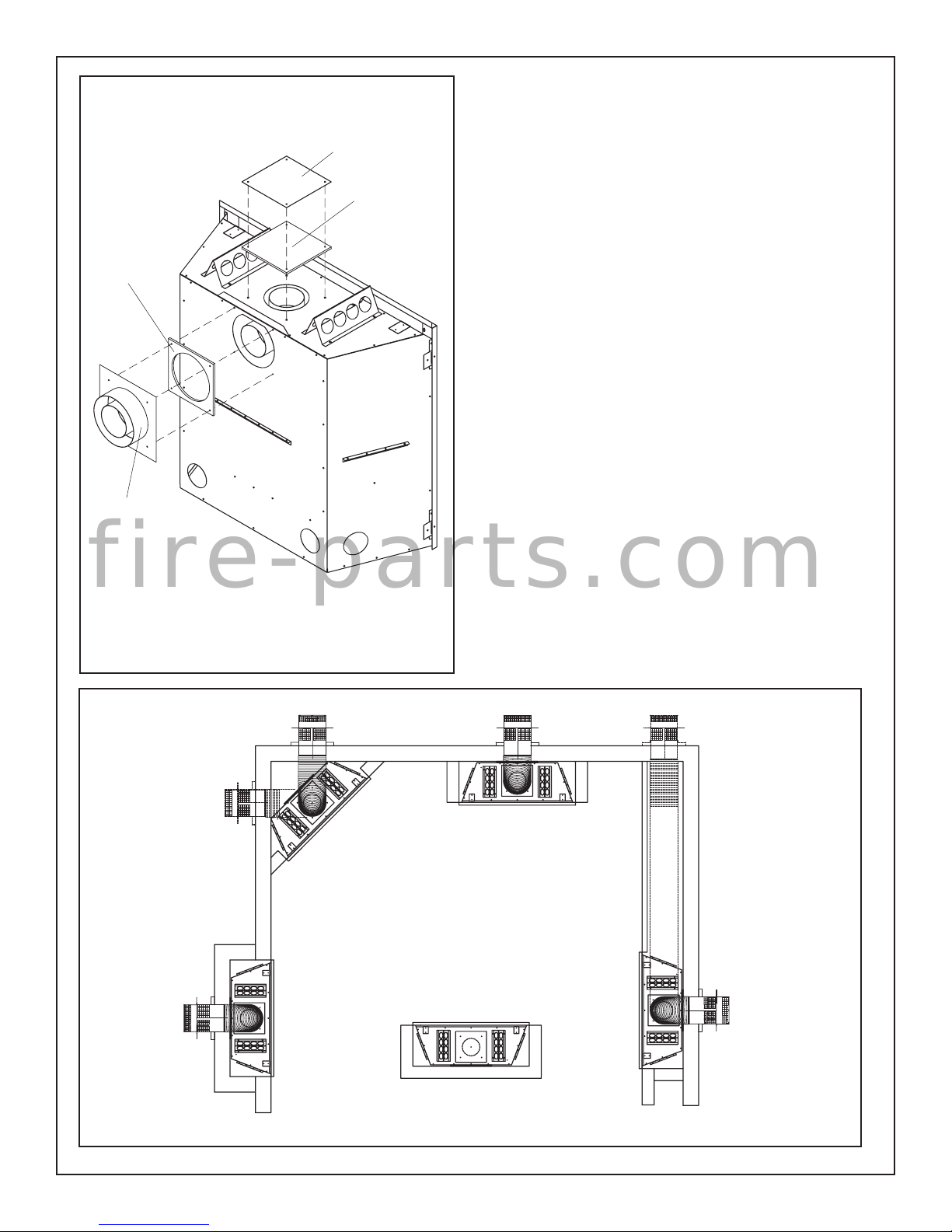
Fig. # 22
Vent
Cover Plate
Gasket
Adapter
Gasket
Vent
Adapter
Vent system components approved for use with the Esteem Fireplace
are shown in Appendix A. The Esteem Fireplace is also tested and
certi ed for use with SIMPSON DURA-VENT DIRECT VENT GS pipe
or SECURITY CHIMNEYS SECURE VENT system (see Optional
Venting section).
NO OTHER VENTING SYSTEMS OR COMPONENTS MAY BE
USED.
Various combinations of vertical and horizontal runs may be used.
Refer to Fig. #26 and 27 for details. For optimum performance and
ame appearance, keep the vent length to a minimum. Connections
between each vent system component must be tightly joined and
sealed, and secured with sheet metal screws at each joint. A horizontal run of vent must have a 1/4" rise for every 2 ft. of run towards
the termination.
CAUTION: UNDER NO CONDITION SHOULD COMBUSTIBLE
MATERIAL BE CLOSER THAN 1 INCH FROM THE VERTICAL AND
HORIZONTAL SECTIONS OF THE PACIFIC ENERGY FLEX VENT
SYSTEM AND 1-3/4 INCHES FROM THE SIMPSON DURA-VENT
GS AND SECURITY SECURE VENT SYSTEM.
Exterior wall opening:
It is preferred to cut an opening between two building framing members
to avoid any extra framing. Consult your local building codes prior to
proceeding. The vent kit will accommodate a maximum wall thickness
of 11-1/2 inches.
Having determined the vent terminal location, cut and frame an opening
of 10-1/2 inches. The opening may be round or square. Height of
the opening will vary with each installation. As the horizontal vent run
increases, so does the minimum vertical rise (see Fig. #26).
f i r e - p a r t s . c o m
IMPORTANT: When locating this hole it should be noted that
the bottom of the vent terminal must be a MINIMUM of 12 inches
above grade, the top of the vent terminal must be a MINIMUM
of 16-1/4 inches below combustible material such as a deck or
roof overhang and the side of the terminal must be a MINIMUM
of 5-3/4 inches away from an adjacent wall (see Fig. #34).
Fig. # 23
Examples of
Common Locations
040706-44 ESTEEM_CM 13
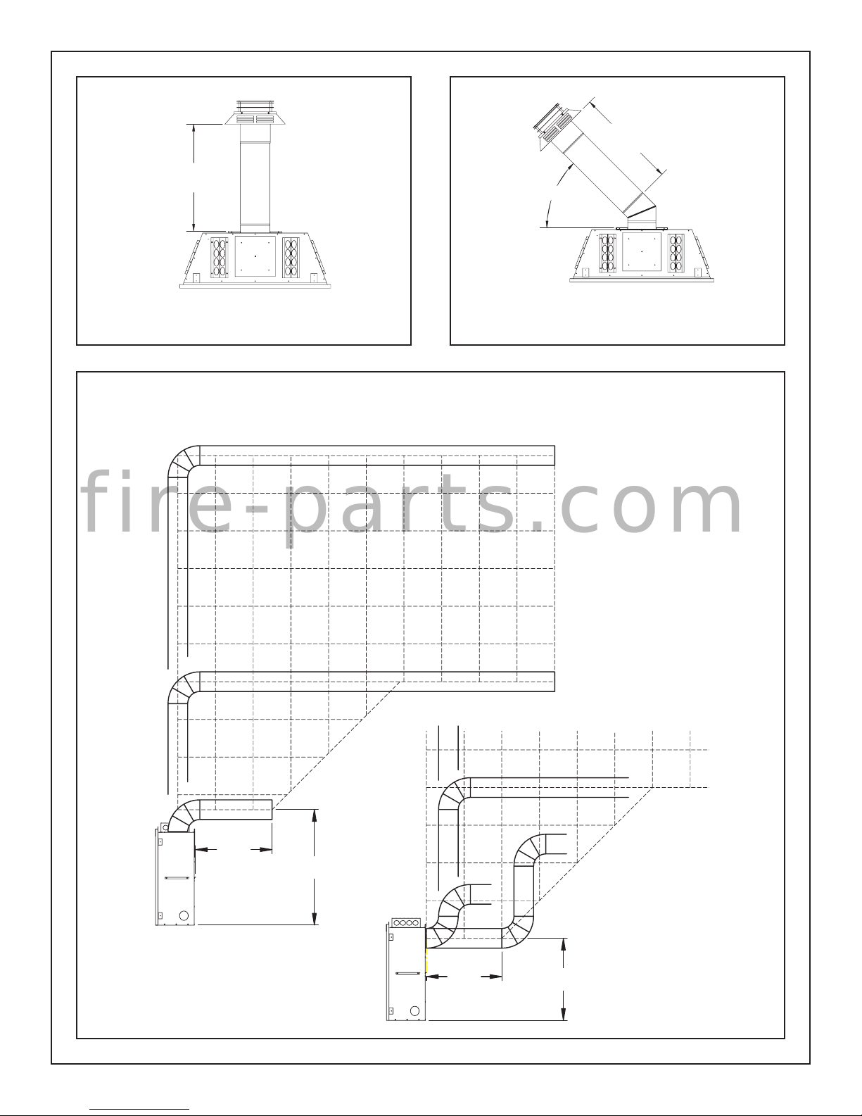
Fig. # 24
Fig. # 25
24"
24"
45˚
Top View
Corner Vent
WALL
TERMINATION
Fig. # 26
10'
Top View
HORIZONTAL RUN
2'
1'
9'
4'
3'
5'
7'6'
9'
8'
10'
MAX.
VENTING CHART
f i r e - p a r t s . c o m
8'
7'
6'
5'
4'
VERTICAL RISE
3'
NOTE: The vent must not exceed
a total length of 20 feet. Any combination of rise and run may be
used but must be constrained to
the boundaries of this chart. For
each additional 90° elbow, reduce
vent length by 2 feet. For each
additional 45° elbow, reduce vent
length by 1 foot.
2'
1'
24"
A = 39 1/2" - Paci c Energy Flex Vent
= 36 3/4" - Simpson Dura-Vent GS
- Security Secure Vent
14 ESTEEM_CM 040706-44
5'
4'
3'
A
2'
1'
24"
26 1/8"
 Loading...