

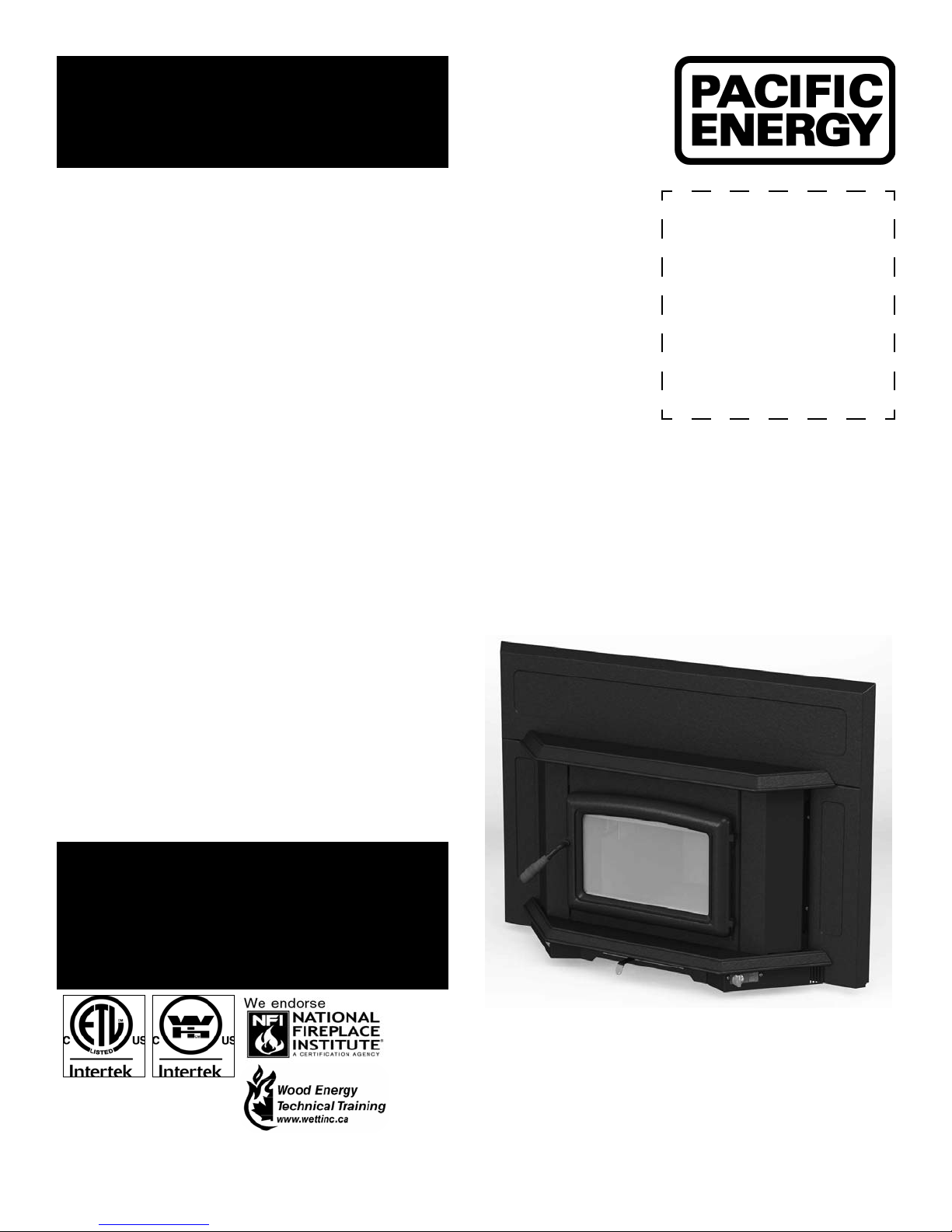
Pacific energy SUPER INSERT DESIGN-E SPNE, SUPER INSERT, DESIGN-E, SPNE, SUPER INSERT DESIGN-E Operating Instructions Manual [en, fr]
...Page 1
IMPORTANT:
THESE INSTRUCTIONS ARE TO
REMAIN WITH THE HOMEOWNER
SAVE THESE INSTRUCTIONS
SAFETY NOTICE
If this stove is not properly installed, a house
re may result. For your safety, follow the
installation directions. Consult local building
SERIAL #
Super Insert
inspector or officials about restrictions and
installation inspection requirements in your
area.
TESTED and LISTED
to ULC S628 / UL 1482
Meets the U.S. Environmental Protection
Agency's July 1990 Particulate Emission
Standards
INSTALLATION
AND OPERATING
INSTRUCTIONS
190913-24 SPNE 5055.101.B
MODEL:
SUPER INSERT
DESIGN-E
SPNE
Page 2

Contents
Safety ............................................................................................ 3
Clearances ................................................................................... 3
Masonry or Factory Built Fireplace ........................................................ 3
Maintenance Checks ................................................................... 4
Dimensions .................................................................................. 6
Installation .................................................................................... 7
Fireplace Speci cations ......................................................................... 7
Into a Masonry Fireplace ....................................................................... 7
Full Flue Liner (Required in Canada) Fig #2 .......................................... 8
Direct Flue Connection (Only permitted in USA) Fig #4......................... 8
Into a Factory Built Fireplace ................................................................. 8
Fan Speed Controller Relocation ........................................................... 9
Surround Assembly and Installation .....................................................11
Combustion Air .....................................................................................12
Operation .................................................................................... 13
Wood Selection.....................................................................................13
How to Test Your Wood .........................................................................13
Lighting the Fire ....................................................................................13
Normal Operation .................................................................................13
Restarting After Extended or Overnight Burns ......................................13
Over Firing ............................................................................................13
More Wood, More Heat .........................................................................14
Proper Draft ..........................................................................................14
Ash Removal ........................................................................................14
Disposal of Ashes .................................................................................14
Blower ......................................................................................... 14
Blower Operation ..................................................................................14
Electrical Supply ...................................................................................14
Creosote ..................................................................................... 15
Formation and Need for Removal .........................................................15
Chimney Fires .......................................................................................15
In Case of a Chimney Fire ....................................................................15
Avoiding a Chimney Fire .......................................................................15
Maintenance ............................................................................... 16
Baffle Removal ......................................................................................16
Replacement Parts .................................................................... 17
Appendix A ................................................................................. 18
Understanding & Operating Your Paci c Energy Stove .........................18
Troubleshooting ....................................................................................19
Firebrick Installation .................................................................. 20
Label .................................................................................................... 23
2
SPNE 190913-24
Page 3
6.5"
15"
10"
16"
Safety
Clearances
READ ALL INSTRUCTIONS BEFORE INSTALLING AND
USING THIS APPLIANCE.
We strongly recommend that smoke detectors be installed.
If smoke detectors have been previously installed, you may
notice that they are operating more frequently. This may be
due to curing of stove paint or fumes caused by accidentally
leaving the re door open. Do not disconnect the detectors.
If necessary, relocate them to reduce their sensitivity.
SAFETY NOTICE: If this stove is not properly installed, a
house re may result. For your safety, follow the installation
directions. Consult local building or re officials about restrictions and installation inspection requirements in your area.
NATIONAL
FIREPLACE
INSTITUTE
CERTIFIED
www.nficertified.org
We recommend that our products be
installed and serviced by professionals
who are certified in the U.S. by the
National Fireplace Institute (NFI)
or in Canada by Wood
Energy Technical
Training (WETT)
Wood Energy
Technical Training
www.wettinc.ca
Masonry or Factory Built Fireplace
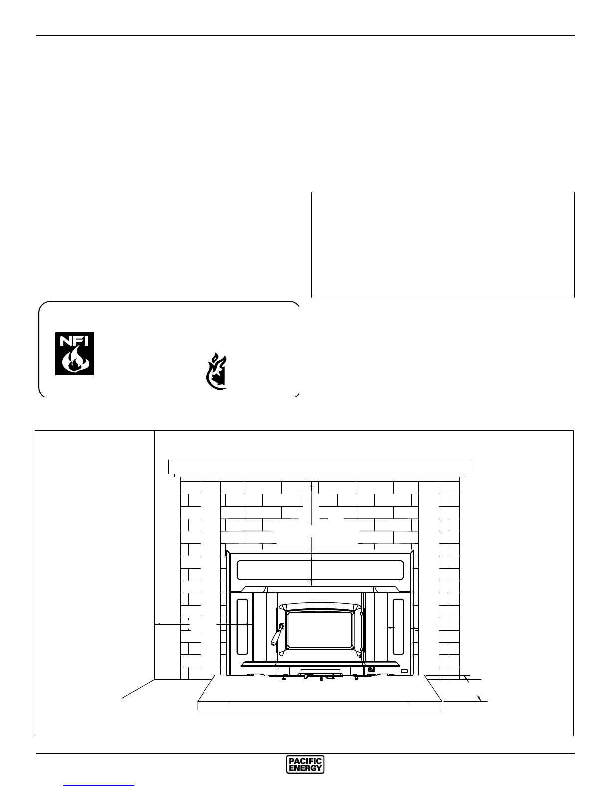
The minimum required clearances to surrounding combustible
materials when installed into a masonry or factory built replace
are listed below and in gure #1.
Minimum Clearances to Combustibles
(Measured From Insert Body)
Adjacent Sidewall .........................10in. (254 mm.)
Mantel .......................................... 15 in. (381 mm.)
Top Facing ...................................15 in. (381 mm.)
Side Facing (1.5 in. extension) ... 6.5 in. (165 mm.)
Fig. # 1
Adjacent Wall
Mantel or Top Facing
Fireplace
Hearth
Side Facing
SPNE 190913-24
3
Page 4

Maintenance Checks
Check the following parts for damage such as cracks, excessive corrosion, burned out sections and
excessive warping: (See website for descriptions and more detail)
Weekly:
- Firebrick - Visual, for cracking.
- Door Gasket - sagging, placement, damage.
Monthly
- Brick rail tabs and brick rails.
- Air riser tube in the back of the rebox.
- Back side of airwash chamber.
- Baffle locking pin.
- Boost tube cover.
When Cleaning the
Chimney System:
- Top baffle board/blanket.
- Baffle.
- Top heat shield and mounting bolt.
- Baffle Gasket.
- Brick Rails.
- Manifold.
- Some warping of the baffle is normal(up to 1/4” or .65cm).
- Replace if the baffle has permanent warping greater than this or has cracking or breakage.
- Please contact your Dealer if you experience any of the damage listed above. Continuing to operate
your stove with broken parts may accelerate damage to other parts and may void your warranty
Blowers:
- The blowers should be cleaned out a minimum every six months by using a vacumn on the blower
intakes to remove any dust and debris. See “Fan Speed Controller Relocation” section on page 9,
steps 1 & 2, for how to remove the panels and access the blowers.
4
SPNE 190913-24
Page 5
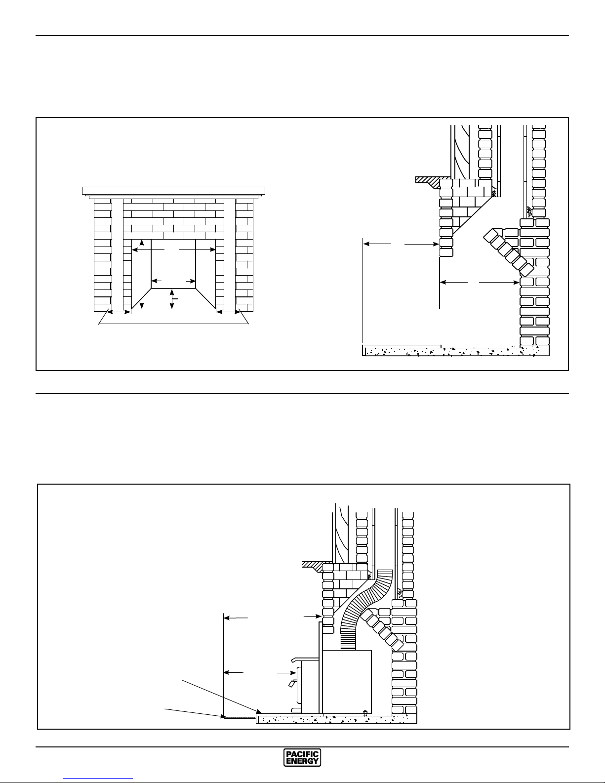
Fireplace hearth requirements: (Measured without the insert)
*
The non-combustible replace hearth must extend 16” in front and 8” beyond each side of the existing replace opening.
MINIMUM FIREPLACE
OPENING AND HEARTH
DIMENSIONS
24”
21”
21 3/4”
18”
8”8”
Ember protection:
Combustible oor in front of the replace insert must be protected from hot embers by non-combustible material
**
extending 16” (USA) and 18” (CANADA) to the ring side and 8” to other sides of the unit.
Consult CAN/CSA-B365 Installation Code for Solid-Fuel-Burning appliances and equipment in Canada, and N.F.P.A.
211 Standard for chimneys, replaces, vents and Solid-Fuel-Burning appliances in USA.
16”
18”
MINIMUM EMBER
PROTECTION
DIMENSIONS
Non-combustible hearth
Non-combustible oor
covering
SPNE 190913-24
22 1/2” USA
24 1/2”CANADA
16” USA
**
18” CANADA
5
Page 6
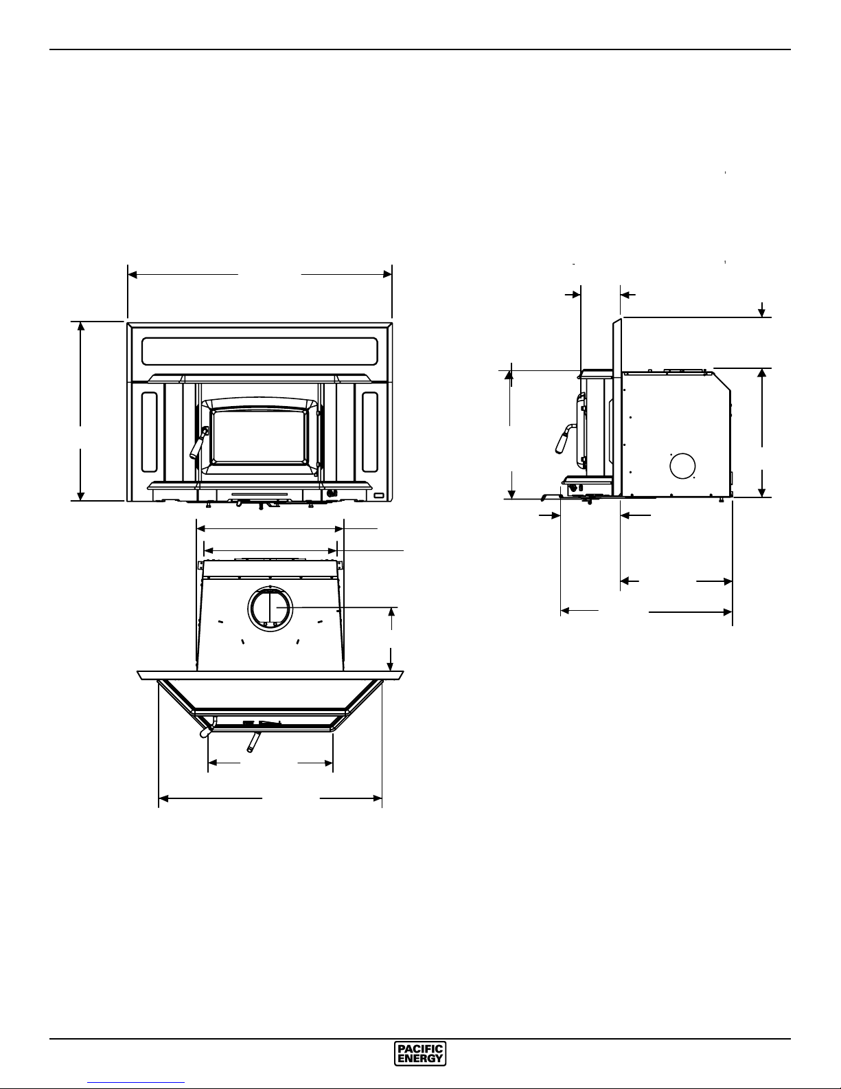
Dimensions
29 3/16”
43 3/8”
23 3/4”
10”
6 1/2”
8 3/4”
21”
20 3/4”
9 1/2”
21 1/2”
18”
28 1/8”
21 1/8”
36”
6
SPNE 190913-24
Page 7
Installation
Your Insert is designed to be installed into a masonry or
factory-built, zero-clearance replace. The masonry replace
must be built according to the requirements of the Standard
of Chimneys, Fireplaces, Vents and Solid Fuel Burning appliances, N.F.P.A. 211 (Latest Edition) or applicable National,
Provincial, State or local codes. The installation shall conform
to CAN/CSA-B365, Installation Code for Solid-Fuel-Burning
Appliances and Equipment. The factory-built, zero-clearance
replace and its chimney must be listed per UL 127 or ULC
S610 standards.
Warning: Under no circumstances is this heater to be installed
in a makeshift or "temporary" manner.
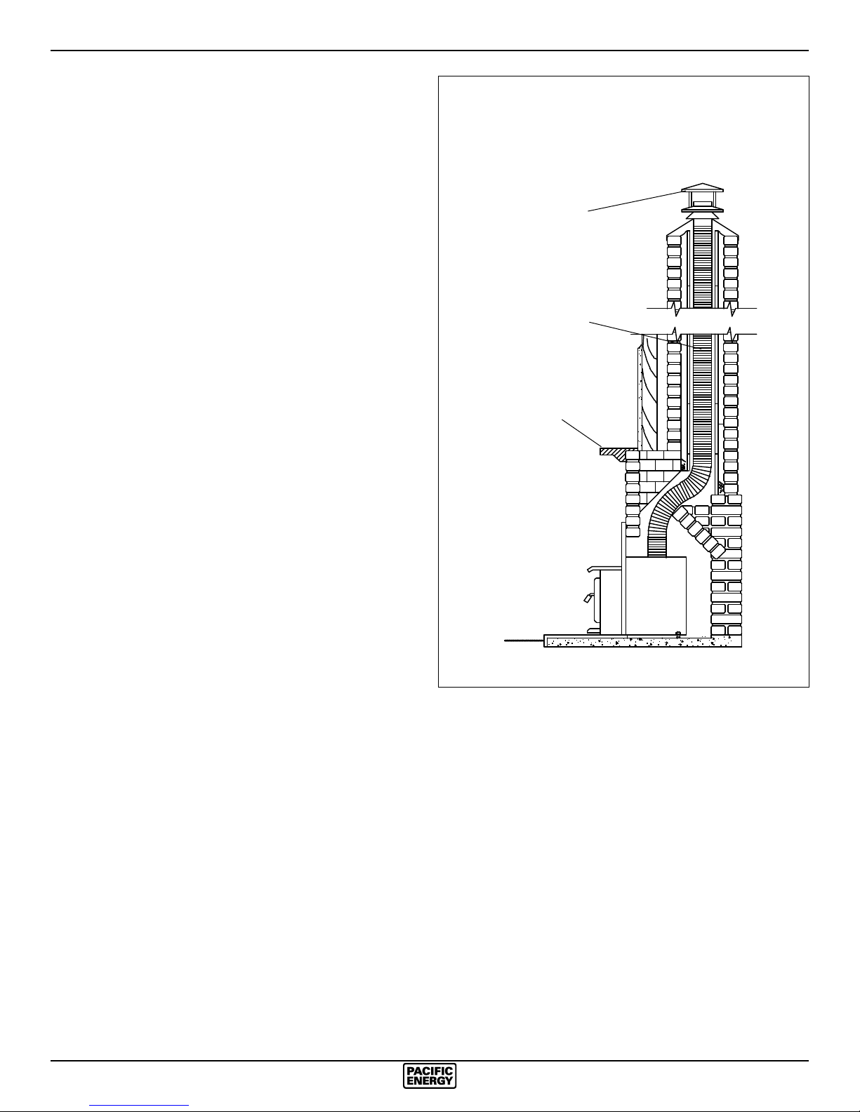
Fig. # 2
Full Flue Liner
(Required in Canada)
Rain Cap
DO NOT CONNECT THIS UNIT TO A CHIMNEY FLUE
SERVICING ANOTHER APPLIANCE.
Fireplace Speci cations
Your replace is required to have the following minimum sizes:
WIDTH (at front) 23 3/4" (602.44 mm)
WIDTH (at rear) 21-3/4" (552.5 mm)
HEIGHT 21" (533.4 mm)
DEPTH 18" (457.2 mm)
Chimney height 15' (minimum)
A metal tag is provided and is to be fastened to the back
wall of the replace, if the replace has been modi ed to
accommodate the insert.
Into a Masonry Fireplace
Inspect your replace for cracks, loose mortar or other physical defects. If repairs are required, they should be completed
before installing your insert.
The replace chimney must be suitable for wood burning use.
Check for creosote build up or other obstructions, especially
if it has not been in use for some time.
The existing replace damper is to be locked open or removed
completely.
WARNING: Do not remove bricks or mortar from your
existing replace.
Exception: Masonry or steel, including the damper plate, may
be removed from the smoke shelf and adjacent damper frame
if necessary to accommodate a chimney liner, provided that
their removal will not weaken the structure of the replace and
chimney, and will not reduce protection for combustible materials to less than that required by the National Building Code.
The Insert must be installed in accordance with local and or
national building codes. The two methods of ue connection
that are acceptable in most areas are:
Full Flue Liner: (Fig.2) where a stainless steel rigid or exible
liner extends from the Insert ue collar to the top of the chimney.
Positive Flue Connection: where a throat blocker plate and a
short connector pipe is used.
Note: A clean-out door may be required under local codes,
when a positive ue connection is used. Consult local codes.
Stainless Steel
Rigid or Flex Liner
Mantel or
Top Facing
Paci c Energy highly recommends the use of a full liner
as the safest installation and providing optimum performance. When connected to a full liner, the Insert is able to
draft correctly and will prevent problems such as difficult
start-ups and smoking out the door.
For difficult installations, this insert is approved for use
with a SPND.3OFFSETA - 3” ue offset box. Only this
offset box is approved for use with this insert. The use
of any other offset box may cause a hazard and/ or void
any warranty.
SPNE 190913-24
7
Page 8
Full Flue Liner (Required in Canada)
Fig #2
This replace insert must be installed with a continuous liner
of 6” diameter extending from the replace insert to the top of
the chimney. The chimney liner must conform to the class 3
requirements of CAN/ULC-S635, Standard for Lining systems
for Existing Masonry or Factory-Built Chimneys or Vents, or
CAN/ULC-S640, Standard for lining systems for New Masonry
Chimneys.
1) Measure the chimney height from the top of the existing
ue to the oor of the hearth. This will allow extra length
of liner for ashing and rain cap.
2) Feed the stainless steel liner from the top of the chimney,
through the damper area and into the replace cavity.
3) Attach a stove connector to the bottom of the liner, as per
the instructions provided with the chimney liner.
4) Push the Insert into position inside the replace and attach
the connector to the stove collar and secure with screws.
Use the rear adjusting legs to level the Insert.
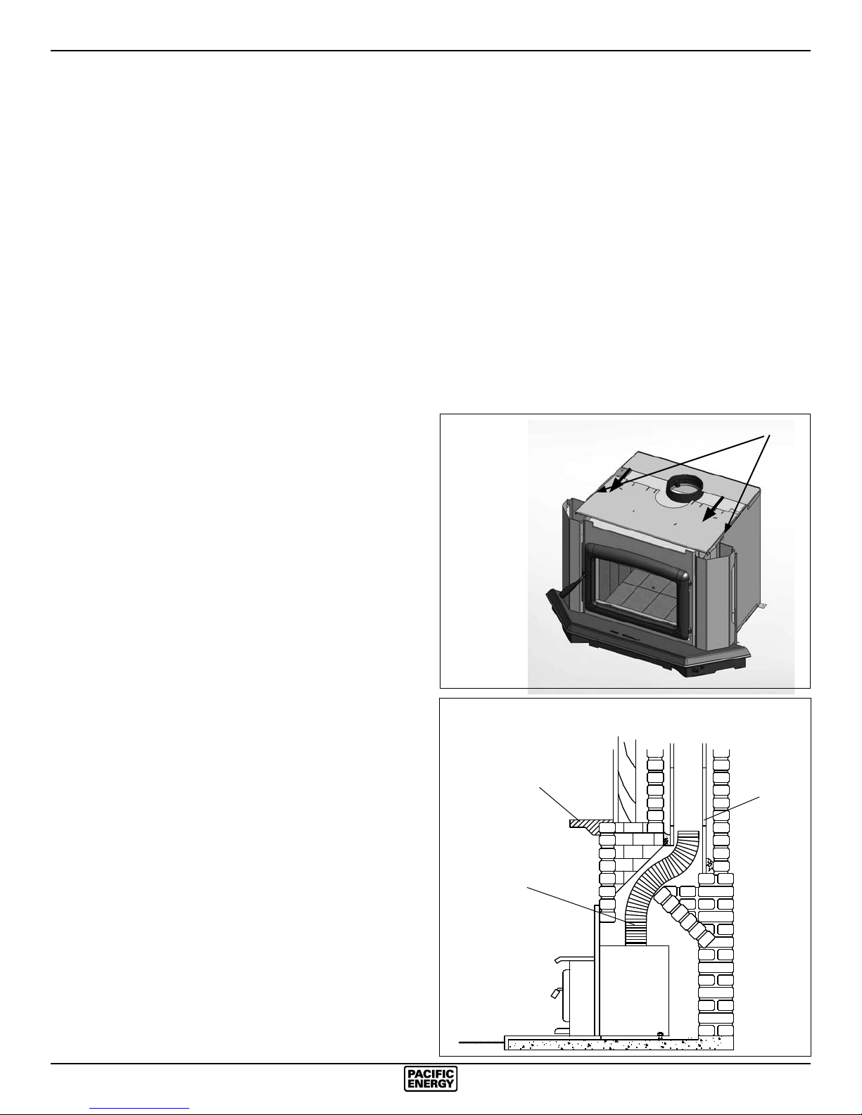
Note: For better access, the top of the casing may be re-
moved (Fig. #3). If it is necessary to get access to the
connector pipe through the ue outlet of the Insert, the
baffle can be removed (see Baffle Removal section).
5) Measure, trim and shape a top ashing to t the existing
chimney ue. Plan for a 1” to 1-1/2” overlap on each side.
Place ashing over top of the liner and seat rmly against
the tile.
6) Screw ashing collar to liner. Caulk gap around ashing
with RTV silicone.
7) Attach a rain cap to the end of the liner. A storm collar
should be used.
Consult your local Dealer about relining your replace chimney.
3) The surround must be sealed to the replace front or the
damper area around the chimney liner must be sealed to
prevent room air entering the chimney cavity of the replace.
4) The air ow within and around the replace must not be
altered by the installation of the Insert (i.e. no blockage of
louvers or cooling air inlet or outlet ports). This includes
the circulating air chambers in a steel replace or metal
heat circulator.
5) Alteration of the replace in any manner is not permitted
with the following exceptions:
a: external trim pieces which do not affect the operation
of the replace may be removed and stored on or within
the replace for re-assembly if the Insert is removed.
b: the chimney damper may be removed to install the liner.
Fig. # 3
SCREWS
Direct Flue Connection (Only permitted
in USA) Fig #4
1) Measure from the rst chimney ue liner to the top of the
Insert. Allow extra length of liner to insert into ue tile.
2) Feed the stainless steel liner through the damper area
and into the rst chimney ue tile. Seal around pipe.
Note: A clean-out door may be required under local codes,
when a direct ue connection is used. Consult local codes.
3) Push the Insert into position inside the replace and attach the connector pipe to the stove collar. Use the rear
adjusting legs to level the Insert.
Note: For better access, the top of the casing may be removed
(Fig. #3). If it is necessary to get access to the connector
pipe through the ue outlet of the Insert, the baffle can be
removed (see Baffle Removal section).
Into a Factory Built Fireplace
Your Paci c Insert may be installed into a factory built replace
with the following requirements:
1) Inspect your replace for damage or other physical defects. The replace must be in good working condition.
If in doubt about its condition, seek professional advice.
Check for creosote build up or other obstructions inside
the chimney, especially if it has not been in use for some
time. Before installing, clean your chimney system thoroughly.
2) A full stainless steel rigid or exible ue liner meeting type
HT requirements (2100°F) per UL1777(U.S.) or ULC S635
(Canada) must be used for both safety and performance.
The liner must be securely attached to the insert ue collar
and the chimney top.
Fig. # 4
Direct Flue Connection
Mantel or
Top Facing
6" Stainless Steel
Rigid or Flex Liner
(USA Only)
Chimney
Flue Liner
8
SPNE 190913-24
Page 9
Fan Speed Controller Relocation
The fan speed controller is factory installed under the ash lip
on the right hand side. If required, it can be relocated to the
left side by following the instructions below. To make this as
easy as possible, it is suggested that this be done prior to
tting the surround and installation into the replace:
1) Lift up on each panel and remove. Set aside to prevent
damage.
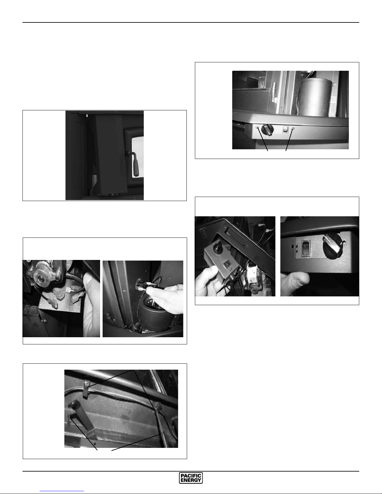
Fig. # 5
2) Disconnect the wires from the fans (LHS & RHS) and
thermal snap switch. Take note of where the wires are
routed and secured. They must be positioned correctly to
avoid damage.
4) Remove the two screws securing the speed controls assembly to the ash lip. The cover plate on the opposite side
can also be removed at this time
Fig. # 8
SCREWS
5) Remove the control assembly from the right hand side of
the ashlip. Flip it over and reattach on the left hand side of
the ashlip. Use the upper screw holes for best alignment.
Fig. # 9 Fig. # 10
Fig. # 6
`
3) Loosen the two bolts that secure the ash lip to the rebox,
carefully lift up the ash lip and remove from the rebox and
unscrew the wire support tabs
Fig. # 7
SCREWS
BOLTS
SPNE 190913-24
9
Page 10
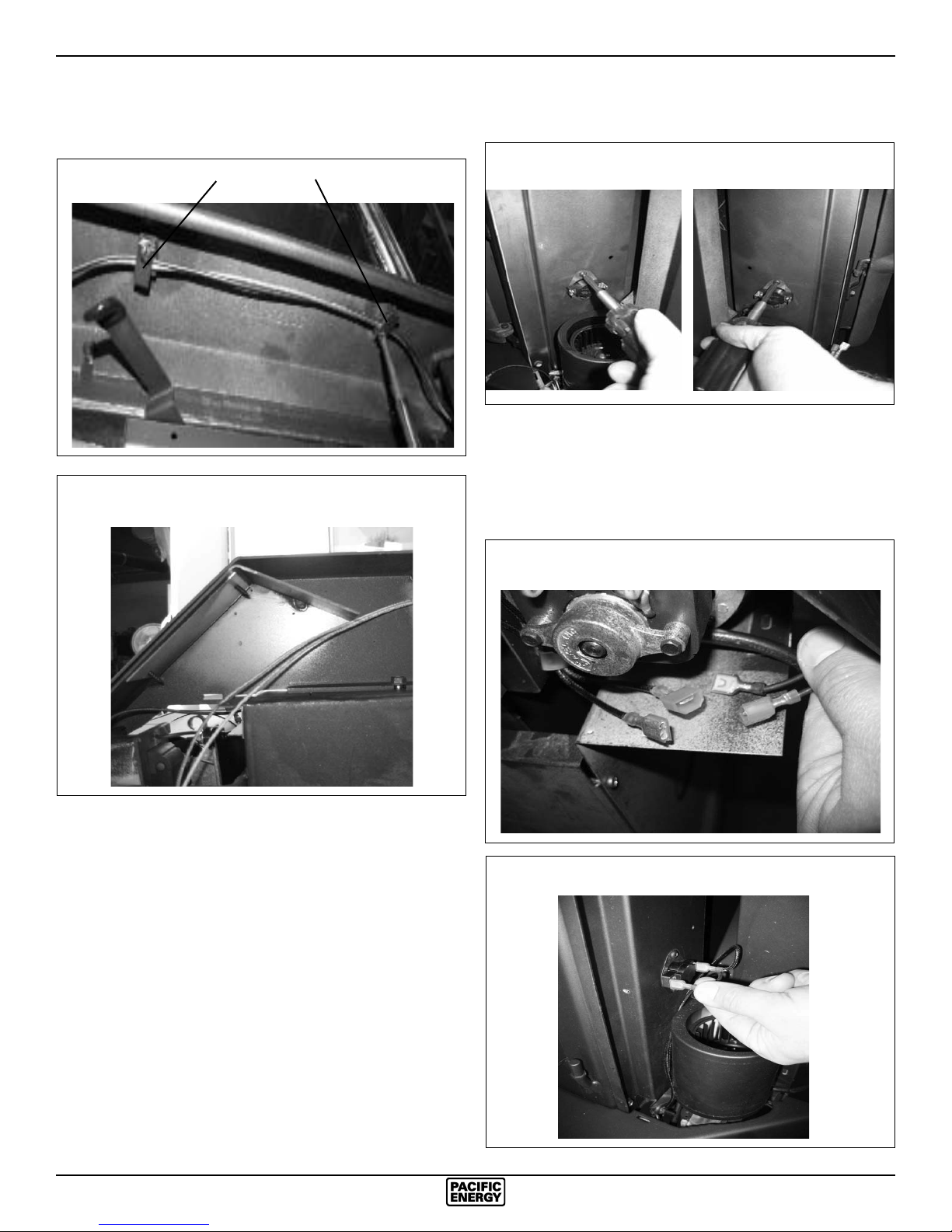
6) Route cable from speed control to fan and reattach wire
support tabs on the underside of the ash lip. Note wire
positions. (Fig.11 & Fig.12)
7) Remove Thermal switch from right hand fan mounting
bracket and relocate to left hand fan mounting bracket.
Fig #13&14
Fig. # 11
Fig. # 12
WIRE SUPPORT TABS
Fig. # 14Fig. # 13
8) Reconnect the wires to the fans (Fig.15) and thermal snap
switch (Fig.16), re t ash lip, sides and top. Ensure that
the power cable is correctly routed through the surround
and it is not touching the rebox side. Wire placement is
important to prevent damage to wires.
Fig. # 15
10
Fig. # 16
SPNE 190913-24
Page 11
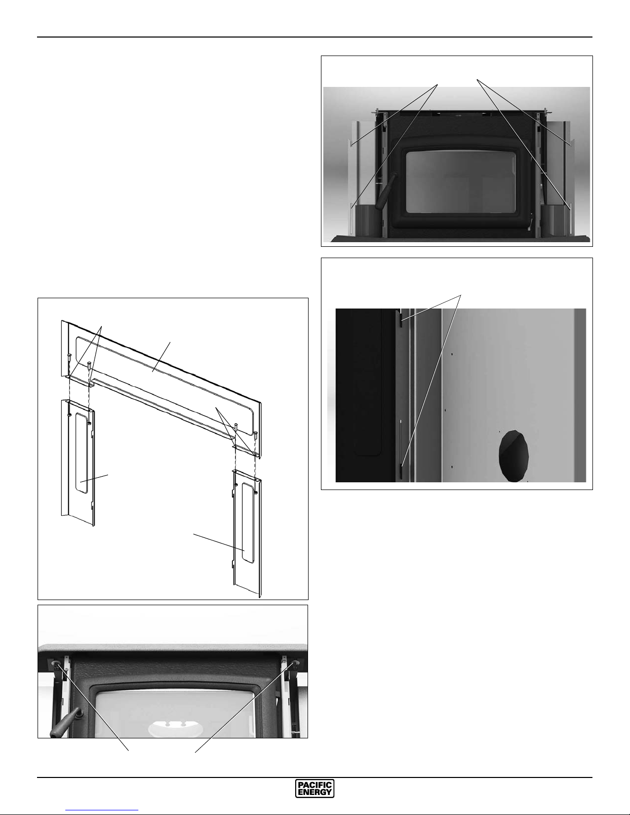
Surround Assembly and Installation
1) Lay part A, B and C face down on a at, non-marring
surface. Fasten together with 1/4" x 1/2" bolts and nuts
provided through holes at points “D” (Fig. #17).
2) Lift the surround assembly to the upright position and make
sure the front face is at and even at the joints.
3) Remove the two front panels as described on page 9 and
then remove the decorative top by loosening the two wing
bolts underneath and sliding it out of the brackets.
(Fig. #18).
4) Slide the assembled surround from the top down and
engage in slots on surround brackets. (Fig. #19 & 20).
5) Push the entire appliance back until the surround assembly
is in contact with the replace structure.
6) Position the decorative bay top onto the rebox top. Align
and refasten the wing screws.
Fig. # 17
D
Part A
Fig. # 19
Fig. # 20
SURROUND SLOTS
SURROUND ENGAGED
IN SLOTS
Fig. # 18
D
Part C
7) Replace the front panels.
Part B
WING BOLTS
SPNE 190913-24
11
Page 12
Combustion Air
Consult local building codes regarding combustion air supply.
Intake or combustion air can be supplied to the Insert in one
of two ways:
1) Outside air (O/A) supply: Remove cover from ash clean
out in existing replace. Place a rodent screen in place
of the cover. Install the Insert as described in the installation section, making sure not to cover the opening of the
air inlet. When installation is complete, seal surround to
replace and anywhere else air may enter. This will ensure
combustion air is drawn from outside the house and into
the 9" x 2" intake at the lower rear of the appliance.
2) Room air supply: Install the Insert as described in the
installation section. When the installation is complete,
do not seal surround to replace. This will allow enough
combustion air to enter the replace cavity and the Insert.
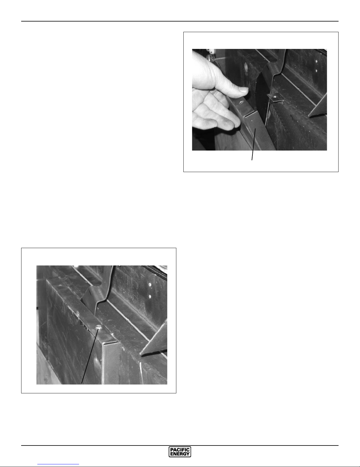
Removal: The O/A cover should be removed prior to installation. For better access, tip the Insert onto its back.
1. Using a 5/16" wrench, remove the screw securing the O/A
cover to the rebox (Fig. #21 & 22).
Fig. # 22
O/A Cover
This unit is not designed to be operated with the ring door
open. In addition to the obvious hazard of sparks landing on
combustibles, an open re door will cause the heater to draw
air from the living space and possibly cause suffocation.
The living space around the heater must be well ventilated
with good air circulation. Anything that may cause a negative
pressure can cause gases or fumes to be pulled into the living area.
Fig. # 21
O/A Cover Screw
12
SPNE 190913-24
Page 13

Operation
Wood Selection
This heater is designed to burn natural wood only. Higher
efficiency and lower emissions generally result when burning
air-dried seasoned hardwoods, as compared to softwoods or
too green or freshly cut hardwoods.
Wood should be properly air dried (seasoned) for six months
or more. Wet or undried wood will cause the re to smoulder
and produce large amounts of creosote. Wet wood also produces very little heat and tends to go out often.
DO NOT BURN:
-*Salt water wood -Coal/charcoal
-Treated wood -*Garbage/Plastics
-Wet or green wood -Solvents
* These materials contain chlorides which will rapidly destroy
metal surfaces and void warranty.
Do not burn anything but wood. Other fuel, e.g. charcoal,
can produce large amounts of carbon monoxide, a tasteless,
odourless gas that can kill. Under no circumstances should
you attempt to barbecue in this heater.
How to Test Your Wood
Normal Operation
1) Set air control to desired setting. If smoke pours down
across the glass (waterfall effect), this indicates you have
shut the control down too soon or you are using too low a
setting. As every home’s heating needs vary (i.e. insulation, windows, climate, etc.), the proper setting can only
be found by trial and error and should be noted for future
burns.
2) To refuel, adjust air control to "H" (Start) position (pushed
to the far left) and give the re time to brighten. Turn the
blowers “OFF”. Open door slowly, this will prevent backpuffing.
3) Use wood of different shape, diameter and length (up to
19"). Load your wood endwise and try to place the logs
so that air can ow between them. Always use dry wood.
4) Do not load fuel to a height or in such a manner that would
be hazardous when opening the door.
5) For extended or overnight burns, unsplit logs are preferred.
Remember to char the wood completely on "H" (high) setting before adjusting air control for overnight burn.
WARNING: Always keep loading door closed when burning. If the door is left partly open, gas and ames may
be drawn out of the replace stove opening creating
risks from re and/ or smoke. This heater is not designed
for open door burning, unless a manufacturer supplied
screen is used.
Add a large piece of wood to the stove when it has a good,
large bed of coals. It is dry if it is burning on more than one
side within one minute. It is damp if it turns black and lights
within three minutes. If it sizzles, hisses and blackens without
igniting in ve minutes it is soaked and should not be burnt.
WARNING: Do not use grates or andirons to elevate the
fuel. Burn directly on the rebricks. Replace broken or
missing bricks. Failure to do so may create a hazardous
condition.
Your Paci c Energy heater is designed for maximum overall
efficiency at a moderate ring rate. Over ring is hazardous
and a waste of fuel. Too slow a burn contributes to creosote
buildup and lowers combustion efficiency.
Lighting the Fire
WARNING: Never use gasoline, gasoline-type lantern fuel,
kerosene, charcoal lighter uid, or similar liquids to start
or ‘freshen up’ a re in this heater. Keep all such liquids
well away from the heater while in use.
1) Adjust air control to "H" (Start) position (pushed to the far
left) and open door.
2) Place crumpled newspaper in the centre of the heater and
criss-cross with several pieces of dry kindling. Add a few
small pieces of dry wood on top.
3) Ignite the paper and close the door.
4) After the re has established itself, open the door and add
a few small logs. Close door.
5) Begin normal operation after a good coal base exists and
wood has charred.
Restarting After Extended or Overnight
Burns
1) Open door and rake hot embers towards the front of the
heater. Add a couple of dry, split logs on top of embers,
close door.
2) Adjust air control to “H” (Start) position (pushed to the far
left) and in just a few minutes, logs should begin burning.
3) After wood has charred, reset air control to desired setting.
4) When burning at a slow rate for extended periods, occasionally maintain a strong re under supervision for a
couple of hours to relieve rebox and chimney deposits
as well as any of the deposits on the glass.
WARNING: This method is not a substitute for regular
chimney inspections and cleaning.
5) To achieve maximum ring rate, set control to “H” (high)
position (pushed to the far left). Do not use this setting
other than for starting or preheating fresh fuel loads.
DO NOT OVERFIRE THIS HEATER: Attempts to achieve
heat output rates that exceed heater design speci cations
can result in permanent damage to the heater and chimney.
WARNING: No alteration or modi cation of the combustion air control assembly is permitted. Any tampering will
void warranty and could be very hazardous.
SPNE 190913-24
13
Page 14
Over Firing
Over ring can be caused by operating the unit with the door
open, damage to door gaskets allowing excess air to enter
the rebox, the use of kiln dried lumber, mill ends or paper
waste and prolonged or continual use on a high burn setting.
More Wood, More Heat
Seasoned wood has approximately 7500 BTU’s per pound. If
you put 10 pounds of wood in your stove for an eight hour burn
the wood will be producing 9375 BTU’s per hour. (7500 BTU x
10 lbs / 8 hrs. = 9375 BTU’s per hr.). If you put 20 lbs of wood
in your stove for an eight hour burn you will get 18,750 BTU’s
per hr. (7500 BTU x 20 lbs / 8 hrs. = 18,750 BTU’s per hr.).
This is only an example and is based on 100% efficiency. In
reality, your stove should perform in the 82% efficiency range.
Experience will give you the right settings for proper combustion and efficient burning. Remember, the air inlet setting is
affected by variables such as type of wood, outside temperature, chimney size and weather conditions. With practice, you
will become pro cient in operating your heater and will obtain
the performance for which it was designed.
Proper Draft
1) Draft is the force which moves air from the appliance up
through the chimney. The amount of draft in your chimney
depends on the length of the chimney, local geography,
nearby obstructions and other factors.
2) Too much draft may cause excessive temperatures in the
appliance. An uncontrollable burn or a glowing red stove
part or chimney indicates excessive draft.
3) Inadequate draft may cause backpuffing into the room and
plugging of the chimney. Smoke leaking into the room
through appliance and chimney connector joints indicates
inadequate draft.
Ash Removal
Whenever ashes get 3 to 4 inches deep in your rebox, and
when re has burned down and cooled, remove excess ashes.
Leave an ash bed approximately 1 inch deep on the rebox
bottom to help maintain a hot charcoal bed.
Blower
The Super Insert comes equipped with twin variable speed
circulating air blowers. The blower system is thermostatically
controlled for automatic operation, as as well manually with a
convenient bypass switch.
Blower Operation
Automatic: To operate the blowers automatically, push the
rocker switch to the “OFF” or “-” position and set the fan speed
control to a desired setting.
This will allow the blowers to turn on automatically once the
Insert has come up to operating temperature. It will also shut
the blower off after the re has gone out and the appliance
has cooled to below a useful heat output range.
Manual: To manually operate the blowers, push the rocker
switch to the “ON” or “O” position and set the fan speed control
to a desired setting. This will bypass the temperature switch
and allow full control of the blower.
Suggested settings:
- Combustion air control setting of “L” (low) position (pushed
to the far right), operate blower speed control on “Low”.
- Combustion air control set at anything above “L” (low),
operate blower speed control at desired setting.
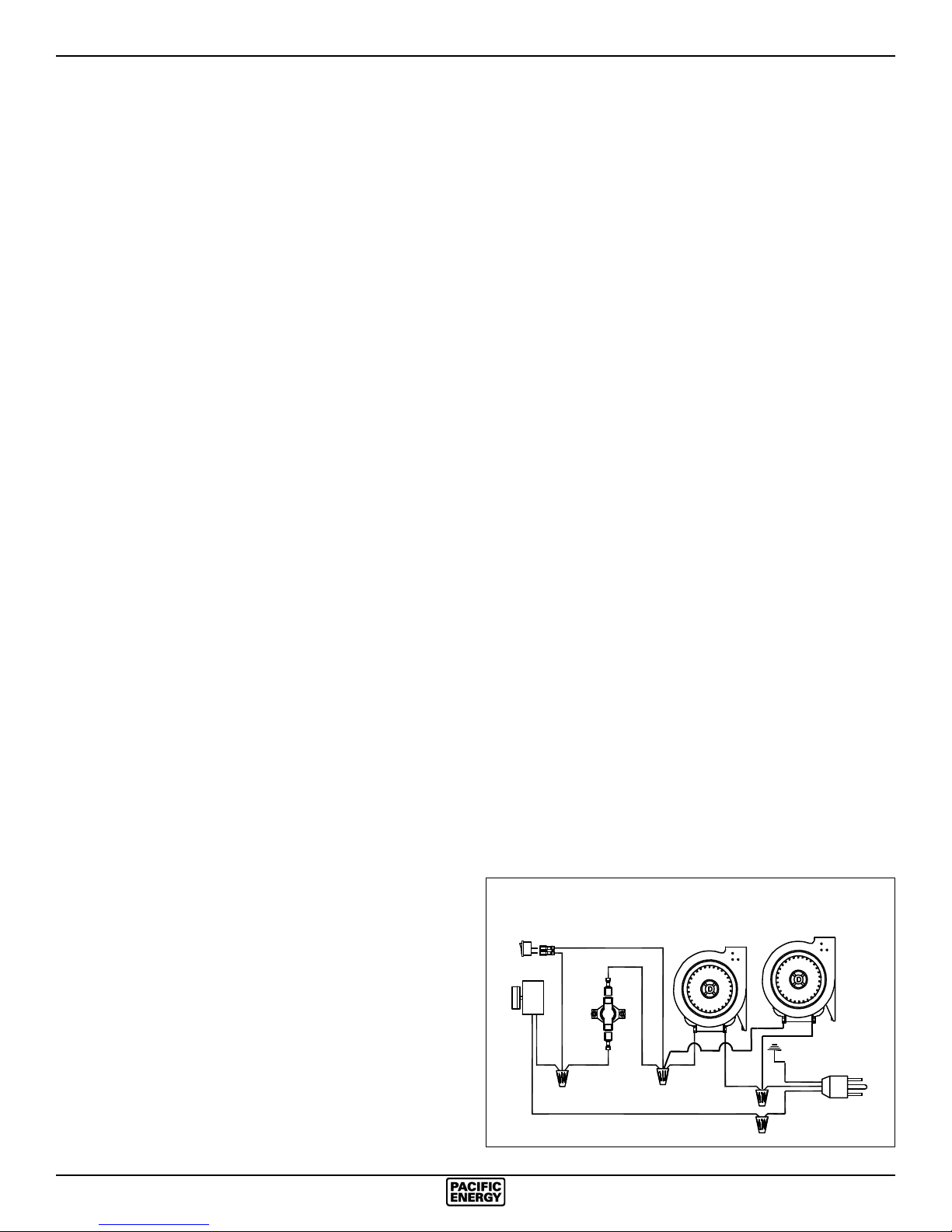
Electrical Supply
Circulating air blower electrical rating; 115V, 60 Hz, 1.1 A. For
your protection against shock hazard, use only a properly
grounded outlet that will accept a three-pronged plug. Do not
cut or remove the grounding prong.
Consult local codes or, in the absence of local codes, with the
current CSA C22.1 Canadian Electrical Code and in the USA
with the National Electrical Code, ANSI/NFPA 70 (latest edition).
Disposal of Ashes
Ashes should be placed in a metal container with a tight tting lid. The closed container of ashes should be placed on
a non-combustible oor or on the ground, well away from all
combustible materials, pending nal disposal. If the ashes
are disposed of by burial in soil or otherwise locally dispersed,
they should be retained in the closed container until all cinders
have thoroughly cooled. Other waste should not be placed
in this container!
14
Fig. # 23
By-pass
Rocker Switch
Speed
Control
Electrical Rating : 115 V, 60 Hz, 1.1A
Thermo
Switch
L1 (white)
L2 (black)
Blowers
G (green)
SPNE 190913-24
Page 15

Creosote
Formation and Need for Removal
When wood is burned slowly, it produces tar and other organic vapours, which combine with expelled moisture to form
creosote. The creosote vapours condense in the relatively
cool chimney ue of a slow burning re. As a result, creosote
residue accumulates on the ue lining. When ignited, this
creosote makes an extremely hot re. The chimney connector and chimney should be inspected at least once every two
months during the heating season to determine if a creosote
buildup has occurred. If creosote has accumulated, it should
be removed to reduce the risk of a chimney re.
1. Highest smoke densities occur when a large amount of
wood is added to a bed of hot coals and the air inlet is
closed. The heated wood generates smoke, but without
ample air, the smoke cannot burn. Smoke-free, clean
burning requires small fuel loads, two or three logs at a
time or 1/4 to 1/2 of a fuel load and leaving the air inlet
relatively wide open, especially during the rst 10 to 30
minutes after each loading, when most of the smoke
generating reactions are occurring. After 30 minutes or
so, the air inlet can be turned down substantially without
excessive smoke generation. Wood coals create very little
creosote-producing smoke.
2. The cooler the surface over which wood smoke is passing, the more creosote will be condensed. Wet or green
wood contributes signi cantly to creosote formation as the
excess moisture that is boiled off cools the re, making
it difficult for the tars and gasses to ignite, thus creating
dense smoke and poor combustion. This moisture-laden
smoke cools the chimney, compounding the problem by
offering the smoke the ideal place to condense.
3. Call local re department. Have a re extinguisher handy.
Contact your local re authority for further information on
how to handle a chimney re. It is most important that
you have a clearly understood plan on how to handle a
chimney re.
4. After the chimney re is out, the chimney must be cleaned
and checked for stress and cracking before starting another
re. Also check combustibles around chimney and the
roof.
Avoiding a Chimney Fire
There are two ways to avoid chimney res:
1. Do not let creosote build up to a point where a chimney
re is possible.
2. Do not have res in the heater that may ignite chimney
res. These are hot res, such as when burning household
trash, cardboard, Christmas tree limbs, or even ordinary
fuel wood; (eg. with a full load on a hot bed of coals and
with the air inlet wide open).
In summary, a certain amount of creosote is inevitable and
must be lived with. Regular inspection and cleaning is the
solution. The use of dry, seasoned wood and ample combustion air will help to minimize the buildup.
Chimney Fires
The result of excessive creosote buildup is a chimney re.
Chimney res are dangerous. Chimney inside temperatures
can exceed 2000 degrees F. This causes much higher than
normal temperatures in the chimney and on its exterior surfaces thus ignition of nearby or touching combustible material
is more likely during a chimney re. Proper clearances are
critical if such a re should occur.
Chimney res are easy to detect; they usually involve one or
more of the following:
- Flames and sparks shooting out of the top of the chimney
- A roaring sound
- Vibration of the chimney
In Case of a Chimney Fire
1. Prepare to evacuate to ensure everyone’s safety. Have
a well understood plan of action for evacuation. Have a
place outside where everyone is to meet.
2. Close air inlets on stove.
SPNE 190913-24
15
Page 16

Maintenance
1. Burn wood only, dry and well seasoned. The denser or
heavier the wood when dry, the greater its heat value. This
is why hardwoods are generally preferred. Green or wet
wood will cause a rapid buildup of creosote. If you feel
it is necessary to burn wet or unseasoned wood, do so
only with the air inlet set open enough to maintain a good
strong re and fairly high chimney temperatures. Do not
attempt to burn overnight using green or wet wood. Wet
wood can cause up to 25% drop in heater output, as well
as contributing signi cantly to creosote buildup.
WARNING: Never use restarter chemicals or any other
volatile liquid to start a re. Do not burn garbage, or ammable uids such a gasoline, naptha, or engine oil. We
strongly recommend that smoke detectors be installed.
2. Remove ashes frequently. Embers can roll out the door
and create a re hazard. Maintain a 1" minimum ash base.
3. If glass becomes darkened through slow burning or poor
wood, it can readily be cleaned with any replace glass
cleaner when stove is cold. Never scrape with an object
that might scratch the glass. The type and amount of
deposit on the glass is a good indication of ue pipe and
chimney buildup. A light brown, dusty deposit that is easily wiped off usually indicates good combustion and dry,
well-seasoned wood and, therefore, relatively clean pipes
and chimney. On the other hand, a black, greasy deposit
that is difficult to remove is a result of wet and green wood
and too slow a burning rate. This heavy deposit is building
up at least as quickly in the chimney.
7. Do not store wood within heater installation clearances,
or within the space required for fuel loading and ash removal. Keep the area around the heater clean and free
of all combustibles, furniture, newspapers, etc.
8. If a plated door requires cleaning, use mild soap and water
only. Use of abrasive cleaners will void warranty.
9. Establish a routine for the fuel, wood burning and ring
technique. Check daily for creosote buildup until experience shows how often you need to clean to be safe.
10. Be aware that the hotter the re, the less creosote is
deposited. Weekly cleaning may be necessary in mild
weather, even though monthly cleaning is usually enough
in the coldest months when burning rates are higher.
11. Instruct all members of your family on the safe operation
of the heater. Ensure they have enough knowledge of the
entire system if they are expected to operate it. Stress the
section on chimney res and the importance of following
the steps outlined in “In Case of Chimney Fire”.
Baffle Removal
The Insert and pipe should be removed from the replace
to clean and inspect. Only if this is not possible should you
remove baffle assembly.
DO NOT OPERATE WITH BAFFLE ASSEMBLY OR INSULATION REMOVED.
Baffle Assembly Removal
Remove retaining pin at the back top of the rebox, just under
the baffle. Lift baffle up and pull forward to disconnect from
the supply tube. Tilt baffle sideways to drop down and remove
from rebox.
WARNING: Only use materials supplied by the manufacturer when doing maintenance or replacements.
4. DOOR GASKET - The gasket used by Paci c Energy
requires only light pressure to seal. This will prolong seal
life. It is important that the door seal be maintained in good
condition. Periodically inspect seals and replace if necessary. Use 7/8” rope gasket, DR31.WDGKIT, obtainable
from your nearest Paci c Energy Dealer.
5. DOOR GLASS - Do not slam loading door or otherwise
impact glass. When closing door, make sure that no logs
protrude to contact the glass. If the glass gets cracked or
broken, it must be replaced before using the stove. Replacement glass can be obtained from your Dealer. The
size required is 8-13/16 x 15-1/4 x 5 mm. Ceramic glass
must be used. Do not substitute with any other type.
To remove broken glass, undo the four retaining screws and
remove the frame noting position for re-assembly. Remove all
particles of glass. Be careful, as they are very sharp. Install
new glass complete with gasket. Replace frame and screws.
WARNING: Do not overtighten, tighten screws very carefully.
- Do not clean glass when hot
- Do not use abrasive cleaners on glass
6. The area where boost combustion air enters the rebox
must be kept clear of excessive ash buildup which will
block air ow. This area is at the front of the rebox.
Inspect gasket between baffle and supply tube. If necessary,
replace with gasket # 139.5 available from your nearest Paci c
Energy Dealer.
Re-install baffle assembly and insulation by reversing order.
16
SPNE 190913-24
Page 17
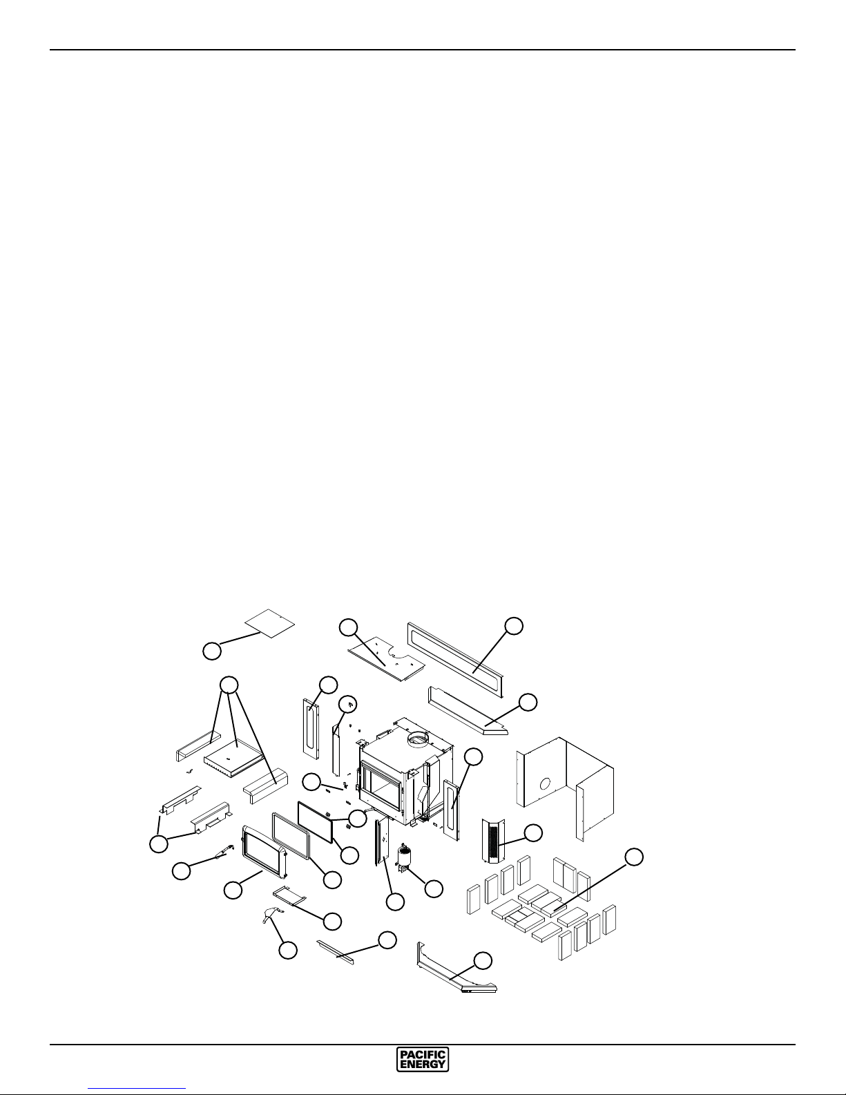
Replacement Parts
(WHEN ORDERING, INCLUDE PART NUMBER WITH DESCRIPTION)
ITEM DESCRIPTION PART NO. ITEM DESCRIPTION PART NO.
1............Surround (* Std-size) .......................SPNE.SRNDA
2............Front Panel, Left ..................................SPNE.4599
3............Bay Top ........................................SPND.50374522
4............Casing Top .......................................... SPND.4545
5............Front Panel, Right ................................ SPNE.4598
6............Ash Lip Assembly ........................SPND.50374512
7............Door Catch (c/w Bolt) .....................WODC.1461.A
8............Glass Clamp Set (4 pc.) ..................... SSER.1425
9............Glass Bar Set (2 pc.) ..................... WODC.414001
10 .......... Replacement Glass (c/w Tape) ......DR31.WGLKIT
..............Door Gasket Kit (7/8”) ....................DR31.WDGKIT
11 .......... Door Casting, Arched Black .................CAST.31ST
..............Door Casting, Radiant Black ...........CAST.31RSST
..............Door Casting, Arched Gold ..................CAST.31GD
..............Door Casting, Radiant Gold ...........CAST.31RSGD
..............Door Casting, Arched Nickel................. CAST.31NI
..............Door Casting, Radiant Nickel ...........CAST.31RSNI
12 .......... Door Handle Assembly .................... WODC.4147C
13 .......... Flame Shield ........................................ WINS.4513
14 .......... Replacement Baffle Kit ................... SSER.DBAKIT
15 .......... Brick Rail, Set ............................... SSER.RAILSET
16 .......... Firebrick Set ..................................... BRIC.SSERA
17 .......... Boost Manifold ............................................... 4105
18 .......... O/A Cover .......................................................4557
19 .......... Air Shutter Assembly ............................ WIND.4531
20..........Blower (RHS) ....................................SPNE.4576R
..............Blower (LHS) ..................................... SPNE.4576L
21..........Blower Mounting Bracket ...............................4541
*22 ........ Control Box Assembly ......................... SPND.4583
* Standard-Size Surround Assembly,
Embossed Panels ..43 3/8" wide x 29 3/16" high
*NOT SHOWN
Fig. # 24
15
12
13
14
11
19
4
1
2
7
8
9
10
18
17
20
21
1
3
1
5
16
Parts may be ordered
from your nearest Paci c
Energy dealer. Contact
6
Paci c Energy for the
location of the dealer
nearest you.
SPNE 190913-24
17
Page 18
Appendix A
Understanding & Operating Your Paci c Energy Stove
The Paci c Energy line of woodstoves is a culmination
of years of research and development. Designed to be
efficient, clean-burning and user-friendly, this heater will
give you years of warm service. However, a knowledgeable
operator is still the most important factor for maximum
performance and part of this is understanding the basic
functions of this design.
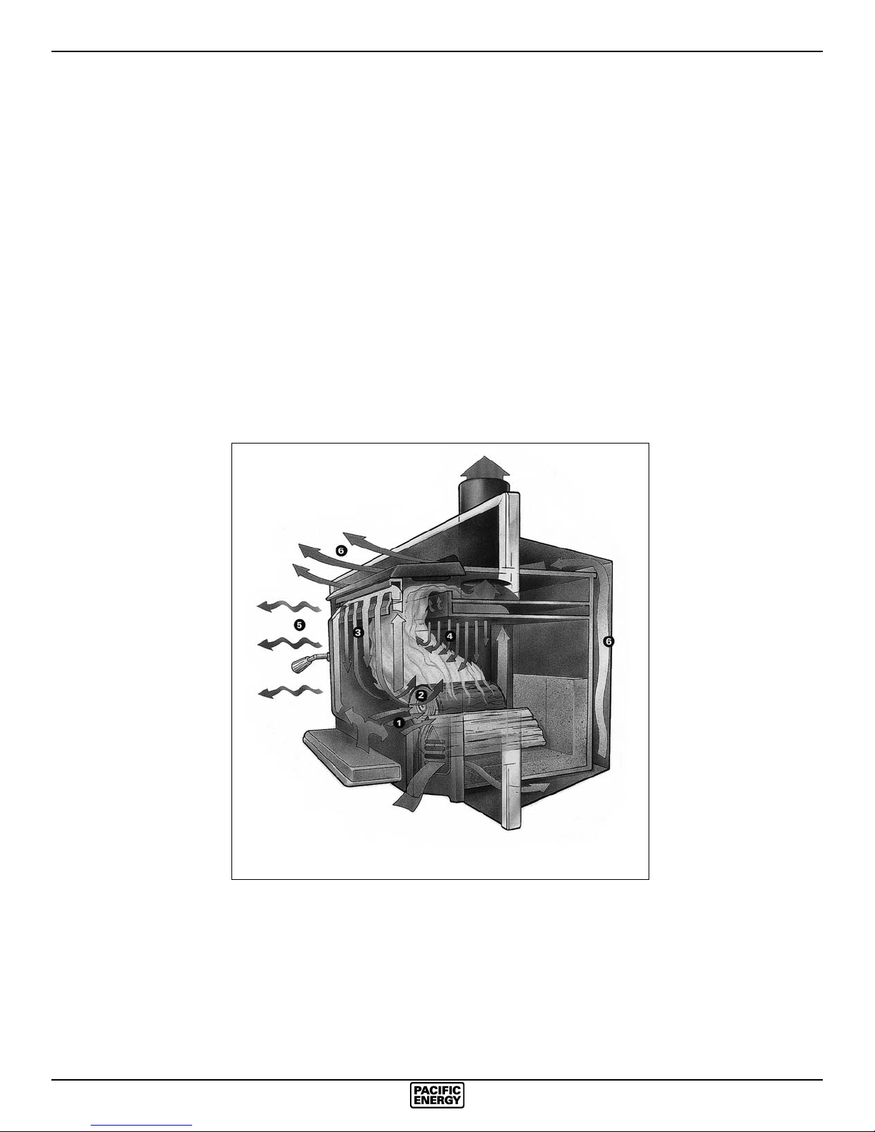
Traditional wood stoves had a basic combustion system
which allowed a considerable amount of heat energy
to escape up the chimney as unburned gases and
particulates (smoke).
Pacific Energy has
designed a system that
solves the problem by
burning the smoke and
releasing the additional
heat to the room.
This system has two
critical design features:
1. Above re secondary
air injection:
The hollow "air baffle"
injects super-heated
secondary air just
above the load. With
the stove at the proper
operating temperature,
this will create a
secondary ame that
will be evident for
approximately 1/3 of
the total burn time.
1 -Boost Air
2 -Main Combustion Air
3 -Air Wash System
should be avoided until the charcoal base has become
quite small.
OPERATING TIPS
1. Always use dry, seasoned rewood, up to 18" long.
Load wood endwise, a mixture of large and small pieces,
on top of a good ash base (1" minimum).
2. Operate on a medium to high setting, for up to 1 hour
from cold start. After the initial warm up period, refuel
and leave the air control on a medium setting for 5 to
10 minutes more and
then set the air control
to the desired position.
3. If a slow burn is
desired, set the air
control to low. Active
secondary burning
should be present
above the wood load.
If it is not present
or goes out shortly
after, proper operating
temperature has not
been reached and the
stove needs additional
warm up time.
For additional
operating, safety
and maintenance
4 -Secondary Combustion Zone
5 -Radiant Heat
6 -Convected Heat
information, refer to the
installation manual.
2. High mass and thermal insulation:
The high mass (weight) acts as a heat storage and the
thermal insulation keeps the combustion zone hot. Active
aming takes place during the rst part of the burn. During
this stage, heat is stored in the mass of the unit and is
later released slowly and evenly. As wood chars, active
aming will diminish. This clean charcoal burning stage
will last for a considerable length of time and refueling
18
SPNE 190913-24
Page 19

Troubleshooting
Problem Cause Cure
Excessive Creosote 1) Wood is too wet - Use dry wood
Buildup
2) Turning down air control - Do not turn down until:
too soon a) there is a good bed of coals
b) the wood is charred
3) Draft too low - Improper chimney height and/or diameter
- Chimney plugged or restricted, check ue
- Provide outside air for combustion
Glass is Dirty 1) See 1, 2, and 3 above
2) Door Gasket leakage - Replace gasket
- Check latch
Low Heat Output 1) Wood is wet - Use dry wood
2) Fire too small - Build a larger re
3) Area too large
4) Poor insulation or open concrete
Won't Burn Overnight 1) Air control set too high - Set control lower
2) Not enough wood - Unsplit wood is preferred for overnight burns
3) Possible air leak - Door gasket needs changing
Stove Won't Burn 1) Combustion air supply - Check outside air supply for obstructions
is blocked (see Combustion Air section)
2) Draft too low - Chimney plugged or restricted
Inspect and clean
- Chimney oversized or otherwise unsuitable
Consult Dealer
19
SPNE 190913-24
19
Page 20
Firebrick Installation
Super Insert
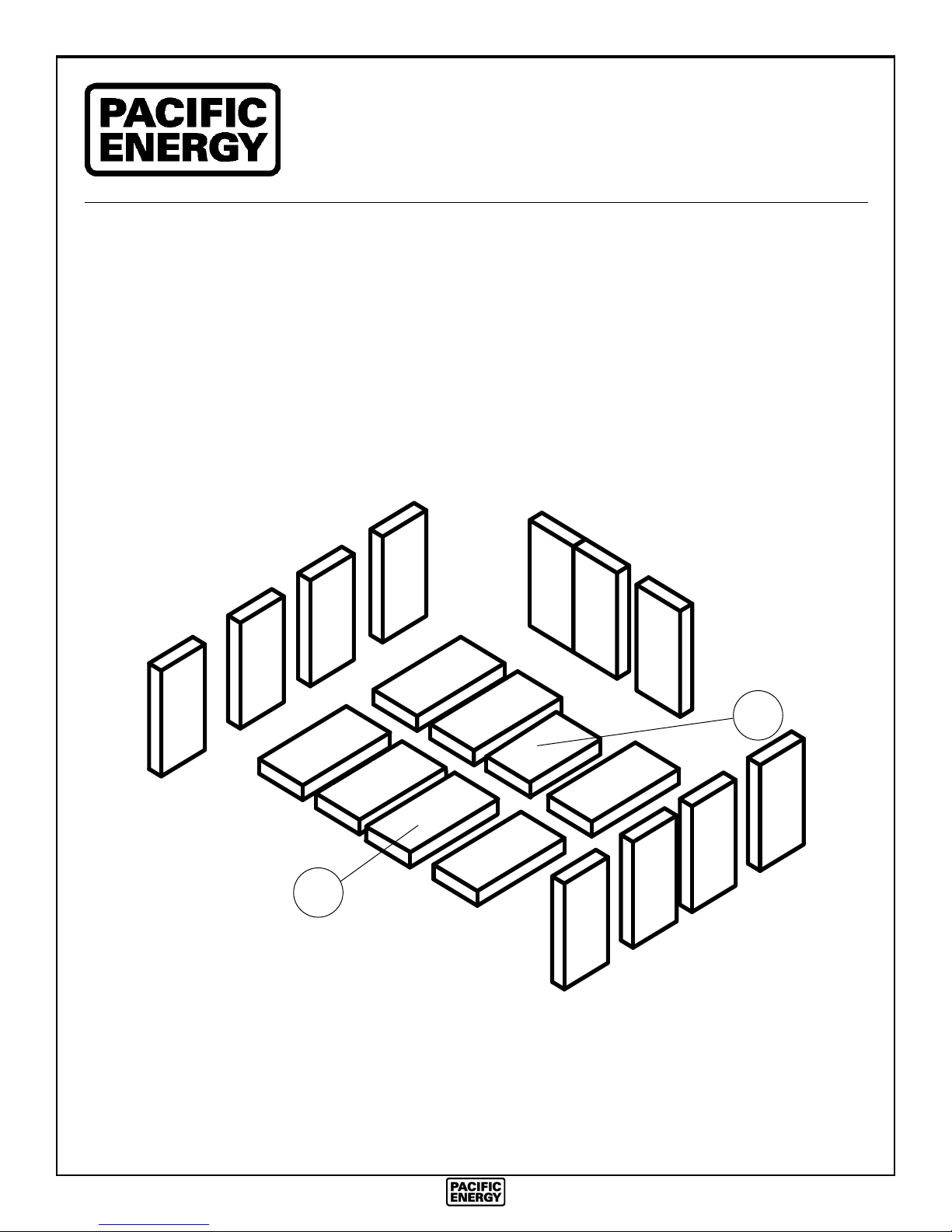
This package contains 18 full-size fi rebricks, as well as 1 cut-size brick.
With the heater in the upright position, install fi rebricks as follows:
- Place fi rebricks on the bottom of the heater fi rst. Total of 7 full-size and 1cut
brick.
- Next, install the side fi rebricks, 4 full-size each side.
- Lastly, install 3 full-size fi rebricks against the rear wall.
B
A
ITEM SIZE PART NUMBER
N. America
A 9” X 4 1/2” X 1 1/4” (230 mm x 115 mm x 32 mm) 5096.99
B 7 1/4” X 4 1/2” X 1 1/4” (184 mm x 115 mm x 32 mm) 245.0
080500-2 WINDBRICK 5055.104
20
SPNE 190913-24
Page 21

NOTES:
SPNE 190913-24
21
Page 22

NOTES:
22
SPNE 190913-24
Page 23
Label
LISTED FACTORY BUILT FIREPLACE ACCESSORY INSERT
CERTIFIED FOR USE IN CANADA AND U.S.A.
TESTED TO / ÉPROUVÉ SELON:
ULCS628-93 / UL1482(2011)
501
MODEL / MODÈLE: SUPER INSERT SERIES / SÉRIE: E
WN#16407 ETL# 4001507
INSTALL AND USE ONLY IN ACCORDANCE WITH PACIFIC ENERGY’S INSTALLATION AND OPERATING INSTRUCTIONS.
CONTACT LOCAL BUILDING OR FIRE OFFICIALS ABOUT CODES, RESTRICTIONS AND INSTALLATION INSPECTION IN
YOUR AREA. INSTALL AND USE ONLY IN MASONRY OR FACTORY BUILT FIREPLACE. DO NOT CONNECT THIS UNIT TO
A CHIMNEY FLUE SERVING ANOTHER APPLIANCE.
COMPONENTS REQUIRED FOR INSTALLATION : FULL FLUE LINER CONFORMING TO CAN/ULC-S635 OR CAN/ULC-S640.
IN U.S.A. FLUE LINER CONFORMING TO UL-1777 OR DIRECT FLUE CONNECTION ASSEMBLY .
OPTIONAL COMPONENTS: 3" VENT OFFSET(SPND.3OFFSETA), FAN, ELECTRICAL RATING 115V, 60HZ, 1.6 AMP. ROUTE
POWER CORD AWAY FROM UNIT.
FOR USE WITH SOLID WOOD FUEL ONLY. DO NOT USE GRATE OR ELEVATE FIRE-BUILD WOOD FIRE DIRECTLY ON
HEARTH. REPLACE GLASS ONLY WITH CERAMIC GLASS. INSPECT AND CLEAN CHIMNEY FREQUENTLY-UNDER CERTAIN CONDITIONS OF USE, CREOSOTE BUILDUP MAY OCCUR RAPIDLY.
OPERATE ONLY WITH FEED DOOR CLOSED. OPEN TO FEED FIRE ONLY.
MINIMUM CLEARANCE TO COMBUSTIBLES (MEASURED FROM INSERT BODY)
DÉGAGEMENT MINIMUM AUX COMBUSTIBLES
A) ADJACENT SIDEWALL/ 254 MM / 10 IN
PAROI LATÉRALE ADJACENTE
B) MANTEL 381 MM / 15IN
C) TOP FACING/ 381 MM / 15IN
REVÊTEMENT SUPÉRIEUR
D) SIDE FACING/ 165 MM / 6.5 IN
REVÊTEMENT LATÉRAL
INSTALL ONLY ON A NON-COMBUSTIBLE HEARTH. COMBUSTIBLE FLOOR BEYOND HEARTH MUST BE PROTECTED BY
NON-COMBUSTIBLE FLOOR MATERIAL EXTENDING IN CANADA: 457 MM/ 18 IN ON THE FIRING SIDE (E) AND 200 MM / 8
IN TO THE OTHER SIDES (F)
IN U.S.A.: 406 MM / 16 IN TO THE FRONT OF (E) AND 200 MM / 8 IN TO THE SIDES OF THE FUEL LOADING DOOR (F)
AU CANADA: LE PLANCHER COMBUSTIBLE DEVANT LE FOYER DOIT ETRE PROTEGE PAR UN MATERIEL A L EPREUVE
DU FEU QUI EXCEDE 457 MM / 18 PO DU CÔTÉ DU CHARGEMENT ET 203 MM / 8 PO SUR LES AUTRES CÔTÉS.
INSTALLEZ ET UTILISEZ SELON LES INTRUCTIONS D’INSTALLATION ET D’OPÉRATION DU PACIFIC ENERGY. BÂTIMENT
OU POMPIERS LOCAUX DE CONTACT AU SUJET DES CODES, RESTRICTIONS ET D’INSPECTION D’INSTALLATION
DANS VOTRE SECTEUR. INSTALLEZ ET EMPLOYEZ SEULEMENT EN MAÇONNERIE OU CHEMINÉE CONSTRUITE PAR
USINE. NE RELIEZ PAS CETTE UNITÉ À UNE CONDUITE DE CHEMINÉE DE CHEMINÉE SERVANT UN AUTRE APPAREIL.
MATERIEL REQUIS POUR L INSTALLATION:PLEIN REVÊTEMENT DE CONDUITE DE CHEMINÉE CONFORMÉMENT À CAN/
ULC-S635 OR CAN/ULC-S640. COMPOSANTS FACULTATIFS: 3” VENT OFFSET(SPND.3OFFSETA), FAN, ÉLECTRIQUE
115V, 60HZ, 1.6 AMP. ITINÉRAIRE POWERCORD À PARTIR D’UNITÉ. POUR UTILISATION AVEC COMBUSTIBLE AU BOIS
SEULEMENT. N’UTILISEZ PAS LA GRILLE OU N’ÉLEVEZ PAS LE FEU EN BOIS DE FIRE-BUILD DIRECTEMENT SUR
LE FOYER. REMPLACES LA VITRE AVEC UNIQUEMENT DE LA VITRE CÉRAMIQUE. INSPECTEZ ET NETTOYEZ LA
CHEMINÉE FRÉQUEMMENT-DANS CERTAINES CONDITIONS D’UTILISATION, L’HABILLAGE DE CRÉOSOTE PEUT SE
PRODUIRE RAPIDEMENT. OPÉREZ SEULEMENT AVEC LA PORTE D’ALIMENTATION FERMÉE. OUVREZ-VOUS POUR
ALIMENTER LE FEU SEULEMENT.
ADJACENT SIDE WALL
B
C
A
F
CLEARANCE TO COMBUSTIBLE
CONSTRUCTION
E
D
F
U.S. ENVIRONMENTAL PROTECTION AGENCY
CERTIFIED TO COMPLY WITH JULY 1990
PARTICULATE EMISSION STANDARDS
190913 5050.74.B SPNE-1
CERTIFICATION
LABEL
CAUTION
PACIFIC ENERGY FIREPLACE PRODUCTS LTD.
2975 ALLENBY RD., DUNCAN, BC V9L 6V8
HOT WHILE IN OPERATION. DO NOT TOUCH. KEEP CHILDREN,
CLOTHING AND FURNITURE AWAY. CONTACT MAY CAUSE SKIN
BURNS. SEE NAMEPLATE AND INSTRUCTIONS.
DATE OF MANUFACTURE
FMAMJJASOND
J
2009 2010 2011 2012 2013
MADE IN CANADA
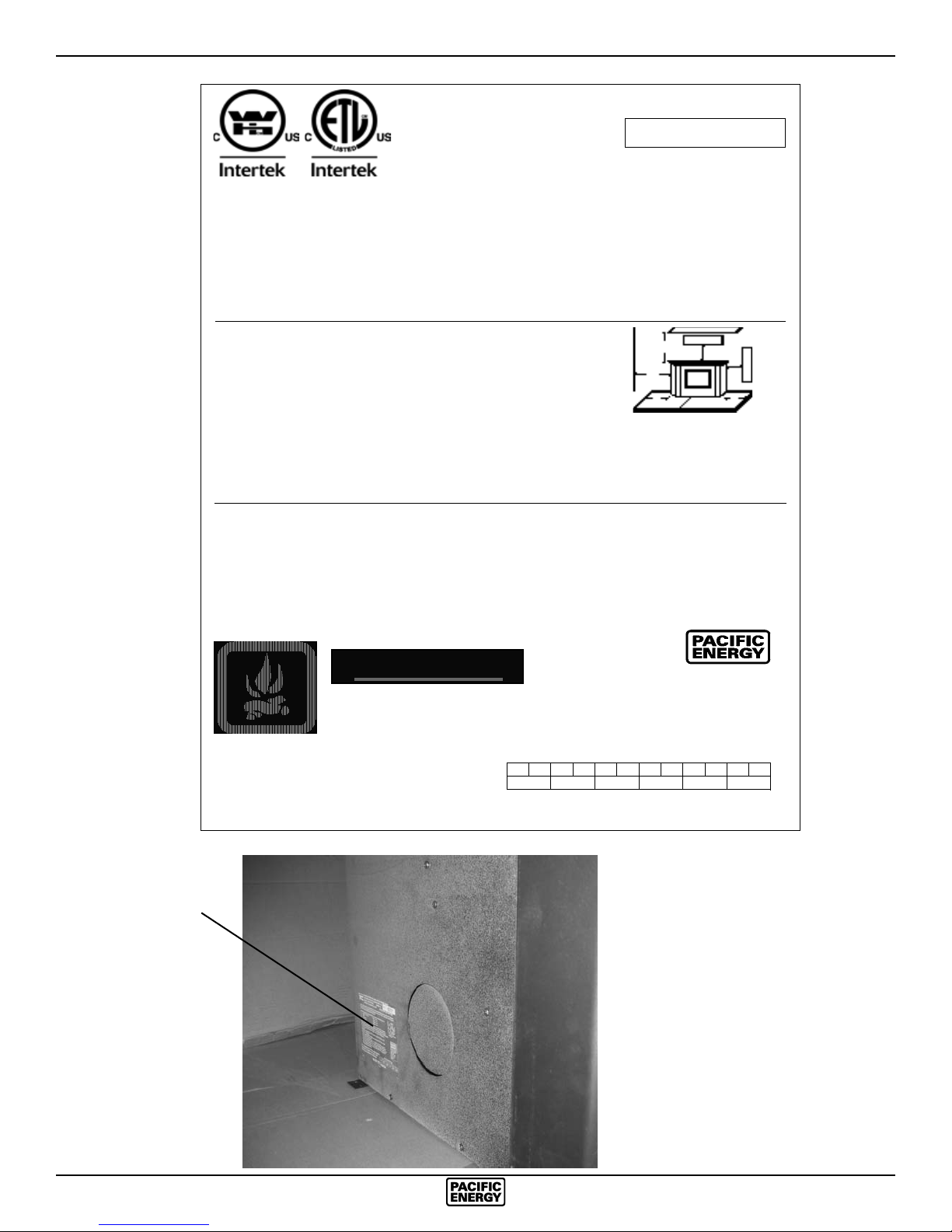
The cerit cation label is located on the left side casing of the insert.
MANUFACTURED BY:
2014
SPNE 190913-24
23
Page 24

PACIFIC ENERGY FIREPLACE PRODUCTS LTD.
2975 Allenby Rd., Duncan, B.C. V9L 6V8
www.paci cenergy.net
Phone: 1-250-748-1184
Printed in Canada
 Loading...