

Pacific energy Classic Gas, Super 27 Gas Installation And Operating Insctruction Manual

IMPORTANT:
THESE INSTRUCTIONS ARE TO
REMAIN WITH THE
HOMEOWNER
WARNING: If the information in these
instructions is not followed exactly, a fire
or explosion may result causing property
damage, personal injury or loss of life.
-- Do not store or use gasoline or other
flammable vapours and liquids in the
vicinity of this or any other appliance.
--WHAT TO DO IF YOU SMELL GAS
• Do not try to light any appliance.
• Do not touch any electrical switch; do
not use any phone in your building.
• Immediately call your gas supplier from
a neighbour’s phone. Follow the gas
supplier’s instructions.
• If you cannot reach your gas supplier,
call the fire department.
--Installation and service must be
performed by a qualified installer, service
agency or the gas supplier.
This appliance may be installed in an
aftermarket permanently located,
manufactured (mobile) home, where not
prohibited by local codes.
This appliance is only for use with the type
of gas indicated on the rating plate. This
appliance is not convertible for use with
other gases, unless a certified kit is used.
Classic Gas
and
Super 27 Gas
SERIES A
DIRECT VENT HEATER
INSTALLATION
AND OPERATING
INSTRUCTIONS
251104-24 CLGA-A 5056.423

Contents
CAUTION ....................................................................................... 3
SAFETY ......................................................................................... 4
MAINTENANCE............................................................................. 4
BASE KIT INSTALLATION ........................................................... 5
DOOR KIT INSTALLATION ........................................................... 5
GAS SUPPLY ................................................................................ 6
FLOOR PROTECTION................................................................... 6
ATTACHMENT TO FLOOR ........................................................... 6
CLEARANCES .............................................................................. 6
VENTING REQUIREMENTS ......................................................... 7
WALL TERMINATION VENTING .................................................. 8
ROOF TERMINATION VENTING .................................................. 9
VENT RESTRICTOR ADJUSTMENT ......................................... 10
VENT TERMINAL CLEARANCES.............................................. 11
GLOWING EMBERS .................................................................... 12
INPUT RATE CONVERSION ...................................................... 13
PROPANE CONVERSION .......................................................... 14
LOG SET ...................................................................................... 15
LIGHTING INSTRUCTIONS ........................................................ 16
FIRST FIRE .................................................................................. 16
OPERATION ................................................................................ 17
PRIMARY AIR ADJUSTMENT .................................................... 17
OPTIONAL WALL SWITCH OR THERMOSTAT ........................ 18
OPTIONAL BLOWER .................................................................. 19
REPLACEMENT PARTS - Classic Gas ..................................... 20
REPLACEMENT PARTS - Super 27 Gas................................... 21
REPLACEMENT PARTS - Burner Assembly............................ 22
RATING LABEL........................................................................... 23
2
Important: When lit for the first time, the appliance
will emit a slight odour for a couple of hours. This is
due to the curing of paints, sealants and lubricants
used in the manufacturing process. This condition is
temporary. Open doors and windows to ventilate
area. If optional fan kit has been installed, place fan
in the "OFF" position. Smoke and fumes caused by
the curing process may cause discomfort to some
individuals.
It is normal for fireplaces fabricated of steel to give off
some expansion and/or contraction noises during the
start up or cool down cycle. Similar noises are found
with your furnace heat exchanger or cook stove oven.
CAUTION
FOR YOUR SAFETY - Do not install or operate your Pacific
Energy heater without first reading and understanding this
manual. Any installation or operational deviation from the
following instructions voids the Pacific Energy Warranty and
may prove hazardous.
This appliance and its individual shutoff valve must be
disconnected from gas supply piping system during any
pressure testing of that system at test pressures in excess of
1/2 psig. (3.5 kPa).
This appliance must be isolated from the gas supply piping
system by closing its individual manual shutoff valve during
any pressure testing of the gas supply piping system at test
pressures equal to or less than 1/2 psig. (3.5 kPa).
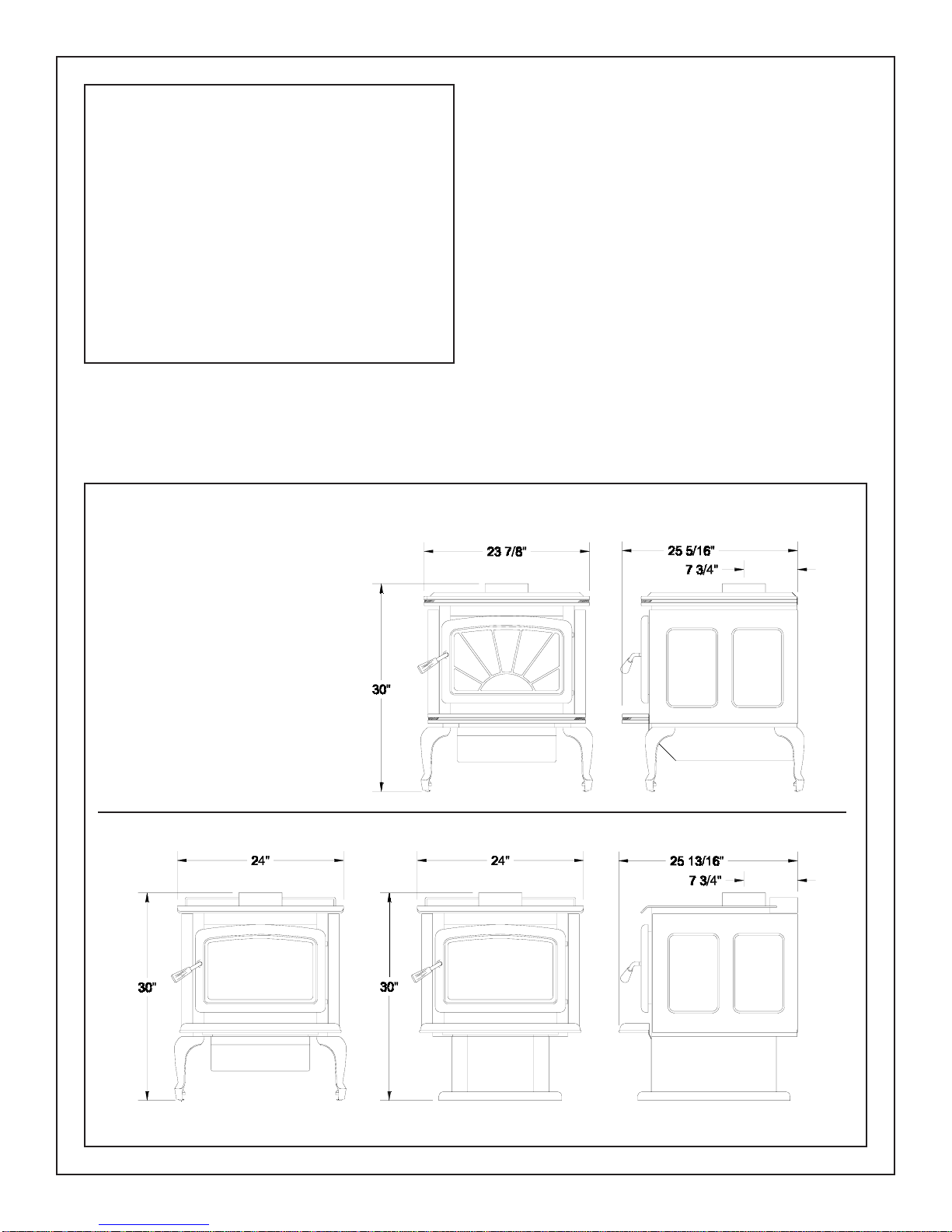
Fig # 1
Classic Gas
Super 27 Gas
Leg Model Pedestal Model
3
SAFETY
MAINTENANCE
• Due to high temperatures, this gas appliance should be
located out of traffic and away from furniture and draperies.
• Children and adults should be alerted to the hazards of
high surface temperatures and should stay away to avoid
burns or clothing ignition.
• Young children should be carefully supervised when
they are in the same room as the appliance.
• Clothing or other flammable material should not be
placed on or near the appliance.
• Under no circumstances should this fireplace be
modified. Any grill, panel or door removed for servicing the
unit must be replaced prior to operating. Failure to do so
may create a hazardous condition.
• Installation and repair should be done by a qualified
service person. The appliance should be inspected before
use and at least annually by a professional service person.
More frequent cleaning may be required due to excessive
lint from carpeting, bedding material, etc. It is imperative
that control compartments, burners and circulating air
passageways of the appliance be kept clean.
It is Pacific Energy’s policy that no responsibility is assumed
by the Company or by any of its employees or
representatives for any damages caused by an inoperable,
inadequate, or unsafe condition which is the result, either
directly or indirectly, of any improper operation or
installation procedures.
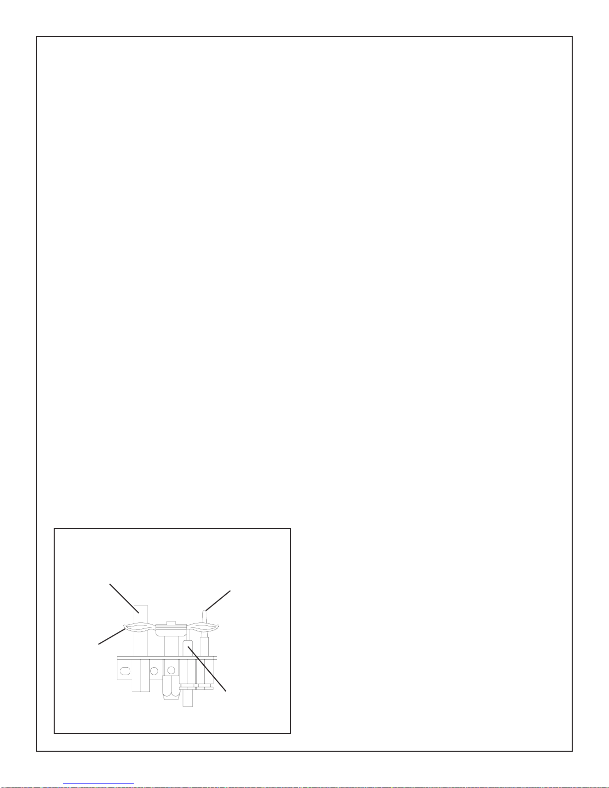
Fig. # 2
Caution: Turn off gas and electrical power supply and allow
ample time for unit to cool before servicing appliance. It is
recommended that this appliance and venting should be
inspected at least once a year by a qualified service person.
Do not use this heater if any part has been under water.
Immediately call a qualified service technician to inspect the
heater and to replace any part of the control system or gas
control which has been under water.
Door Glass
Warning: Do not operate appliance with glass panel
removed, cracked or broken. Replacement of glass should
be done by a licensed or qualified service person.
Do not strike or otherwise impact the glass in anyway that may
cause it to break. If the glass becomes cracked or broken, it
must be replaced before using the fireplace. Replacement
glass can be obtained from your nearest Pacific Energy
dealer. The size required is 9 1/8" x 15 5/8" x 5 mm. Use
ceramic glass only. Do not substitute with any other type.
To remove broken glass, undo the four retaining screws and
remove the frame, noting position for re-assembly. Remove
all particles of glass. Be careful as they are very sharp. Install
new glass complete with gasket. Replace frame and screws.
Annual Inspection:
a) Clean air passage ways of excessive lint and dust buildup
from carpeting, bedding material, etc. The flow of ventilation
air must not be obstructed.
b) Inspect logs and burner assembly for lint and soot buildup. If excessive build-up of soot is present, have a qualified
service person inspect and adjust unit for proper combustion.
Clean logs and burner with a vacuum cleaner, paying close
attention to the ports on the burner.
c) Check the pilot system for proper flame size and operation.
Clean pilot free of lint and dust. (See Fig. #2)
d) Check that the vent pipe and vent terminal are open and
free from blockage or debris. If the venting system is
disassembled for cleaning, it must be properly assembled
and re-sealed.
e) Check door and glass panel gasket, replace if necessary.
It is important that the glass and door seal be maintained in
good condition.
Note: The appliance area must be kept clear and free from
combustible materials, gasoline and other flammable vapours
and liquids.
THERMOPILE
PILOT
FLAME
4
THERMOCOUPLE
Periodically:
a) Viewing glass may be cleaned with fireplace glass cleaner.
b) Exterior finish may be cleaned with mild soap and water.
Caution:
- do not use abrasive cleaners on glass or any other part of this
appliance.
- do not clean glass when hot.
ELECTRODE
BASE KIT INSTALLATION
Crate removal
1) Carefully remove crate top, side supports and plastic
cover bag.
2) Leave the unit on the pallet.
Leg Kit (Classic Gas model only)
1) Remove the 1/2" nuts and washers from the studs on the
bottom corners of the stove using a 3/4" wrench. Save nuts and
washers for later use.
2) Remove the lag bolts that secure the unit hold down
brackets to the pallet.
2) Remove the hold down brackets and discard.
3) Position the legs onto the studs.
4) Place 1/2" washer over the studs and secure in place
with 1/2" nut previously removed.
4) Remove the unit from the pallet and install.
Pedestal Kit (Super 27 Gas model only)
1) Remove the ash lip assembly and pedestal from the
shipping box.
2) Align ash lip assembly mounting screws into slots of the
pedestal door and secure in place.
3) Using a 3/4" wrench, remove the 1/2" nuts and washers
from the studs on the bottom corners of the stove. Save
nuts and washers for later use.
4) Lift the unit off the hold down brackets and carefully
place unit on its back, taking care to not damage the
restrictor positioning panel located on the back of the
unit.
5) Align the pedestal mounting holes with the studs on the
stove.
6) Secure the pedestal to the stove with the 1/2" nuts and
washers previously removed.
7) Carefully place the unit in an upright position.
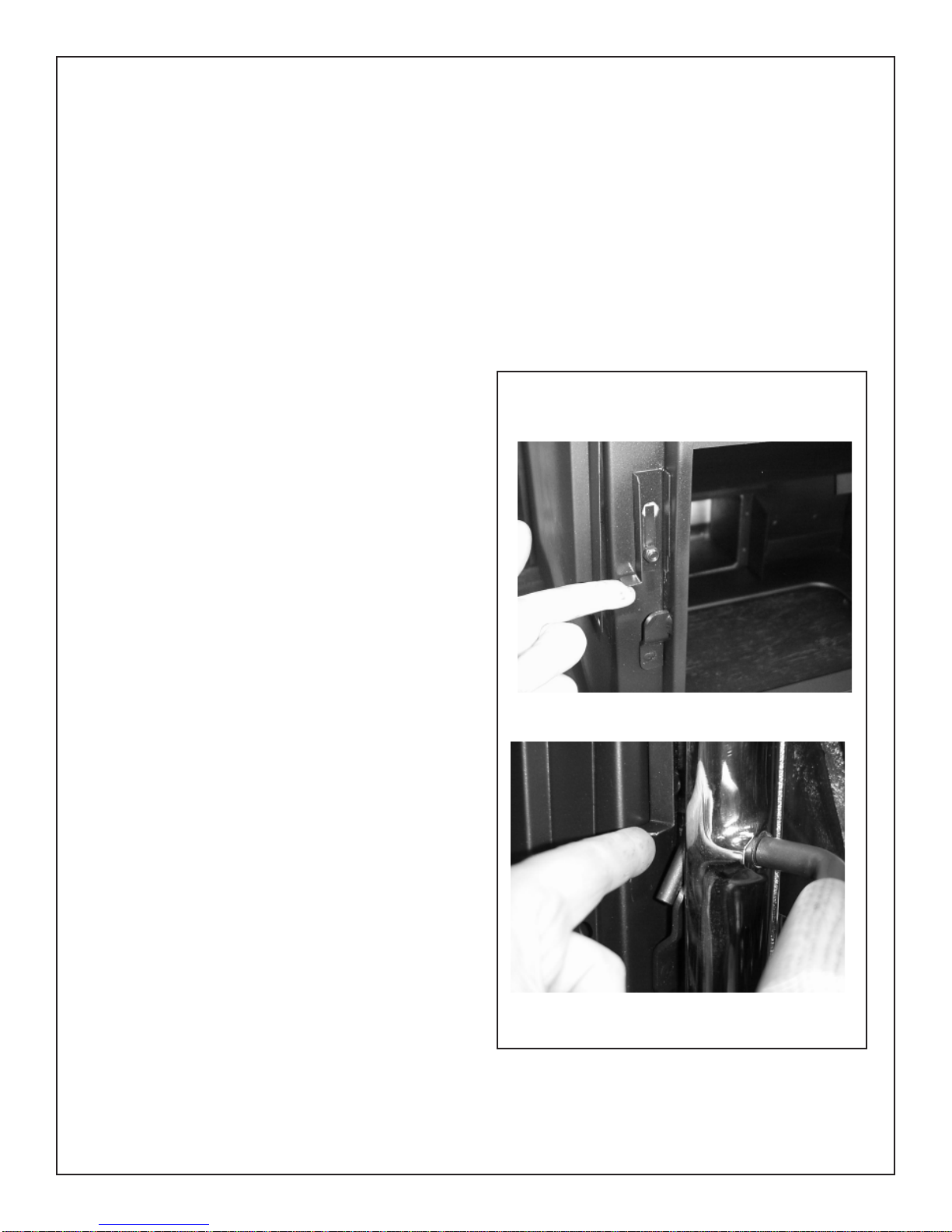
DOOR KIT INSTALLATION
1) Remove door from packing box and inspect.
2) Position door onto hinge pins located on the right side
of the firebox opening.
3) Latch door closed by lifting safety catch and rotating
door handle counter-clockwise till latched.
Fig. # 3
Leg Adapter (Super 27 Gas model only)
1) Remove the ash lip and adapter from the shipping box.
2) Align the ash lip mounting slots with the studs on the front
control access door. Secure in place with 1/4" nuts.
3) Using a 3/4" wrench, remove the 1/2" nuts and washers
from the studs on the bottom corners of the stove. Save
nuts and washers for later use.
4) Lift the unit off the hold down brackets and carefully
place unit on its back, taking care to not damage the
restrictor positioning panel located on the back of the
unit.
5) With the control access door facing up, align the adapter
mounting holes with the studs on the stove bottom.
6) Position the legs on to the studs.
7) Place 1/2" washer over the studs and secure legs in
place with 1/2" nut previously removed.
8) Carefully place the unit in an upright position.
5
GAS SUPPLY
CLEARANCES
Caution: The gas line should be installed by a qualified
service person in accordance with all building codes.
Consult local and/or national building codes before
proceeding.
Correct gas line diameter must be used to assure proper
operation. The gas control is equipped with a captured screw
type pressure test point, therefore it is not necessary to provide
a 1/8 inch N.P.T. plugged tapping pressure test port for
checking gas pressure immediately upstream of the gas
supply connection to the appliance.
The gas valve inlet accepts a 3/8" N.P.T. fitting. For leg model
units, it is recommended to use the optional flex gas connector
(#GASC.GASCON). Route the gas connector inside the
adapter to the rear. Fasten connector to the right side near the
back with the bracket. Alternately, the gas supply line may
enter through the 4" diameter hole located in the base of the
leg adapter. This will allow the installation of the optional
blower kit.
Correct gas pressure requirements:
Natural Gas Propane
Min. Pressure 5.0" wc 11.5" wc
(For purpose of input adjustment)
Max. Pressure 10.5" wc 13.0" wc
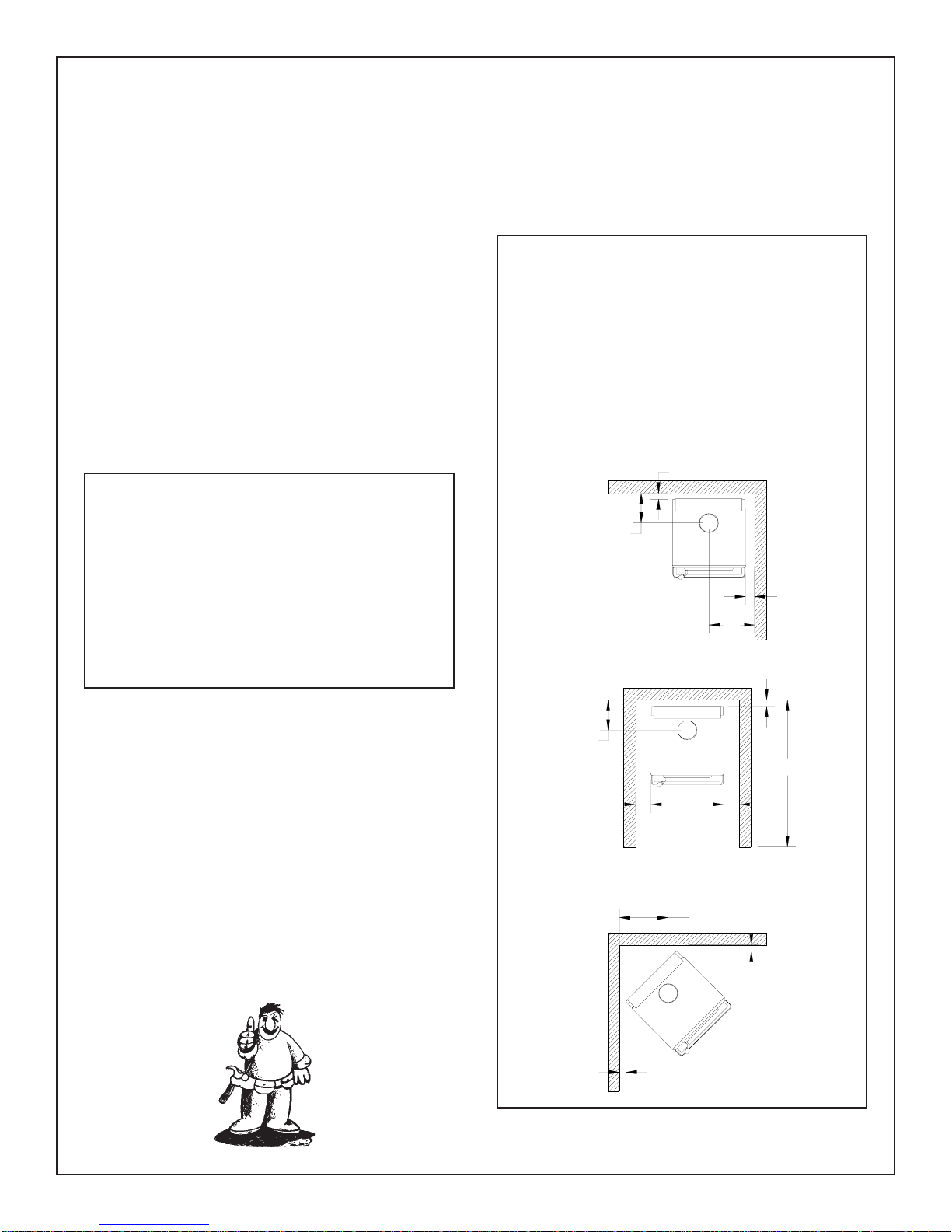
The minimum clearances from the appliance to combustibles
are shown on Fig. #4. Adequate clearances around air
openings and combustion air supplies are required.
Fig. # 4
Minimum Clearance
to Combustibles
Sidewall to Appliance 3 in. (76 mm)
Rearwall to Appliance 2 in. (51 mm)
Corner to Appliance 2 in. (51 mm)
Alcove sidewall to Appliance 5 in. (127 mm)
Alcove minimum width 34 in. (864 mm)
Alcove maximum depth 48 in. (1.2 m)
Alcove minimum height 61 in. (1.5 m)
2"
9 3/4"
3"
Manifold Pressure
Maximum 3.8" wc 11.0" wc
Minimum 1.1" wc 2.9" wc
FLOOR PROTECTION
Both, the Classic Gas and Super 27 Gas Heaters, may be
installed directly on a combustible floor. If the appliance is to
be installed directly on carpeting, combustible floor tile or
other combustible material other than wood flooring, the
appliance shall be installed on a metal or wood panel
extending the full width and depth of the unit.
ATTACHMENT TO FLOOR
Mobile Home installations require that the appliance be firmly
attached to the structure. Once the appliance is in it's final
location, secure the unit in place through holes in the pedestal
base. The holes are located on the left and right hand side of
the base.
9 3/4"
15"
2"
48"
5"
ALCOVE HEIGHT
61" MINIMUM
15 3/4"
2"
5"
2"
6
VENTING REQUIREMENTS
The heater installation and venting must conform with local
codes or, in the absence of local codes, with the current
Canadian Installation Code, CAN/CGA-B149.1 (in Canada)
or the current National Fuel Gas Code, ANSI Z223.1 (in the
USA). Only qualified (licensed or trained) personnel should
install this product.
The Classic Gas and Super 27 Gas Heaters are tested and
certified for use with SIMPSON DURA-VENT DIRECT VENT
GS pipe or SECURITY CHIMNEYS SECURE VENT system.
Vent components approved for use are listed in Figure 4. Kits
for venting either through the wall or vertically through the roof
are available from the vent system manufacturer or your
nearest Pacific Energy Authorized Dealer.
Before installing the vent system, the installer should read
these instructions to ensure proper installation requirements
are maintained. Follow vent pipe manufacturer's instructions
for assembly and installation.
NO OTHER VENTING SYSTEMS OR COMPONENTS MAY
BE USED.
CAUTION: UNDER NO CONDITION SHOULD
COMBUSTIBLE MATERIAL BE CLOSER THAN 1 INCHES
FROM ANY VERTICAL OR HORIZONTAL VENT SECTIONS.
Connections between each vent system component must be
tightly joined and sealed, and secured with sheet metal
screws at each joint.
Consult your local Building Codes before beginning the
installation.
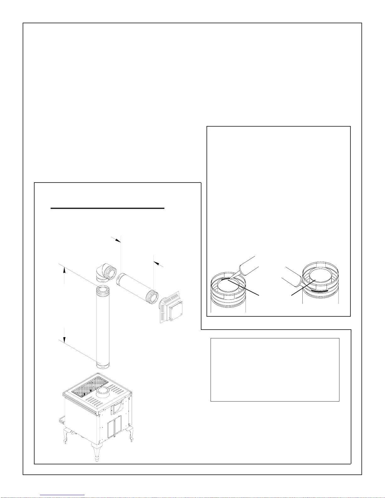
Vent Pipe Sealant
SIMPSON DURA-VENT DIRECT VENT GS pipe: All
vent pipe sections must be sealed. Run a 1/8 inch
wide bead of sealant around the male end of the outer
pipe and female end of the inner pipe as shown
below, and twist-lock the vent pipe sections together.
Fig # 5
WALL TERMINATION
Minimum Installation
Horizontal Run
*
Minimum
Vertical Rise
2 Feet
Maximum
1 Foot
SECURITY CHIMNEYS SECURE VENT system: If
only one elbow is used in the vent system, sealant is
not required. Simply twist-lock the vent pipe sections
together. If more than one elbow is used, apply
sealant to inner sleeve of all elbows. Run a 1/8 inch
wide bead of sealant around the female end of the
inner pipe of elbow as shown below, and twist-lock
the vent pipe sections together.
Inner
Pipe Joint
Sealant
Outer
Pipe Joint
Minimum Maximum
Vertical Rise Horizontal Run
2 Feet 1 Foot
3 Feet 2 Feet
4 Feet 3 to 10 Feet
A minimum vertical rise of 2 feet is
*
required for any wall termination. For
horizontal runs greater than 1 foot,
increase vertical rise equally. At 4 feet
of vertical rise, horizontal run may be
up to 10 feet.
7
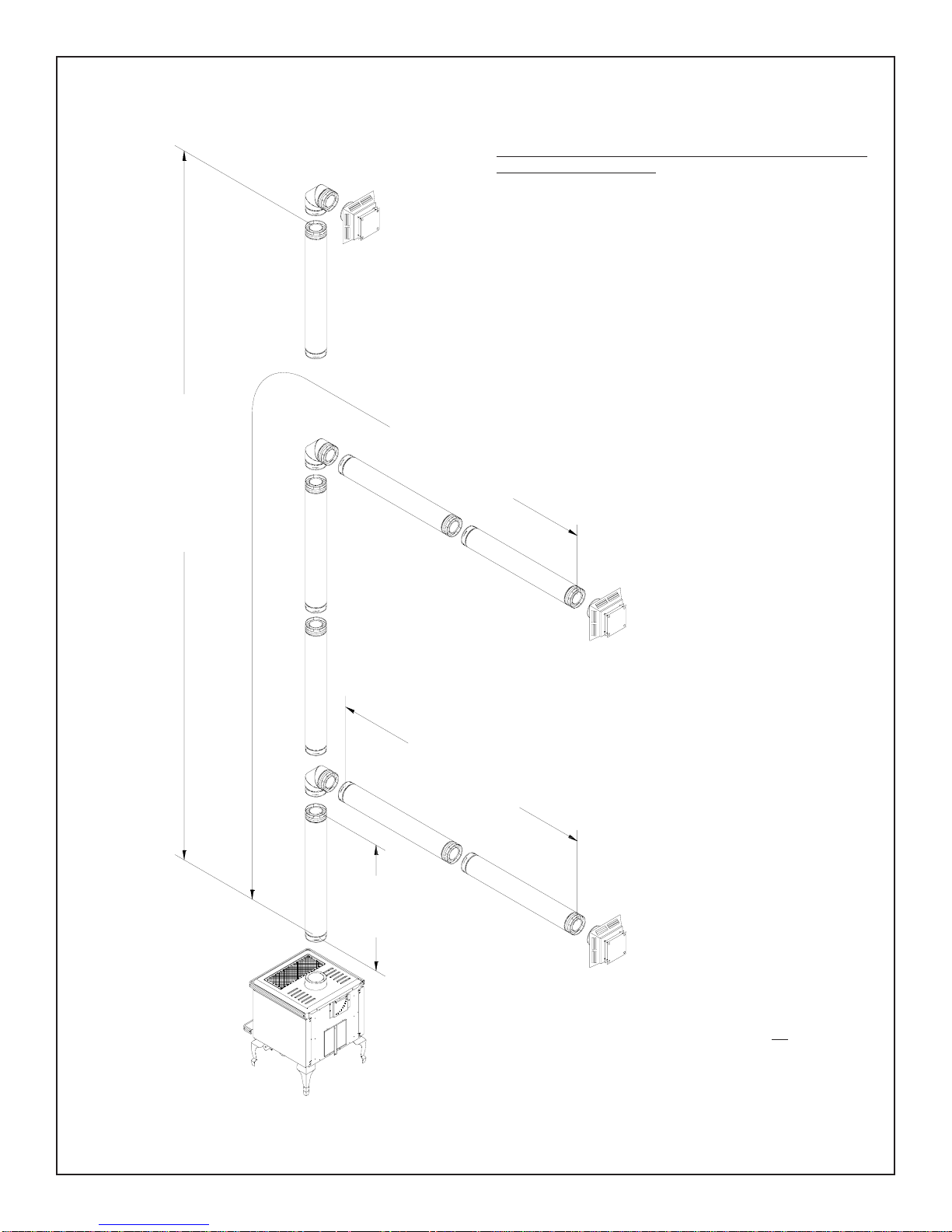
Fig. # 6
Maximum
Vertical Rise
40 Feet
*
Maximum
Vent Length
40 Feet
WALL TERMINATION VENTING
A minimum vertical rise of 2 feet is required for any wall
termination (see Fig. #5).
For horizontal runs greater than 1 foot, increase vertical rise
equally. At 4 feet of rise, the horizontal run may increase up
to and must not exceed 10 feet. A maximum of two 90° or 45°
elbows may be used. If more than 2 elbows are used, reduce
horizontal run by 2 feet for each additional set of elbows.
For optimum performance and flame appearance, keep the
vent length to a minimum. Connections between each vent
component must be tightly joined and sealed. A horizontal run
of vent must have a 1/4 inch rise for every 1 foot of run towards
the termination.
*
Horizontal Run
Minimum Rise
4 Feet
Maximum
10 Feet
Total horizontal run must not exceed 10 feet.
*
Use a maximum of one 90° elbow or two 45°
elbows. If more than 1 elbow is required,
reduce horizontal run by 2 feet for each
additional 90° elbow and 1 foot for each
additional 45° elbow.
8
 Loading...