

Pacific energy SUMMIT INSERT - B Nstallation And Operating Instructions
IMPORTANT:
THESE INSTRUCTIONS ARE TO
REMAIN WITH THE HOMEOWNER
SAVE THESE INSTRUCTIONS
SAFETY NOTICE
If this stove is not properly installed, a house
re may result. For your safety, follow the
installation directions. Consult local building
or officials about restrictions and installation
SERIAL #
inspection requirements in your area.
TESTED and LISTED
to ULC S628 / UL 1482
Meets the U.S. Environmental Protection
Agency's July 1990 Particulate Emission
Standards
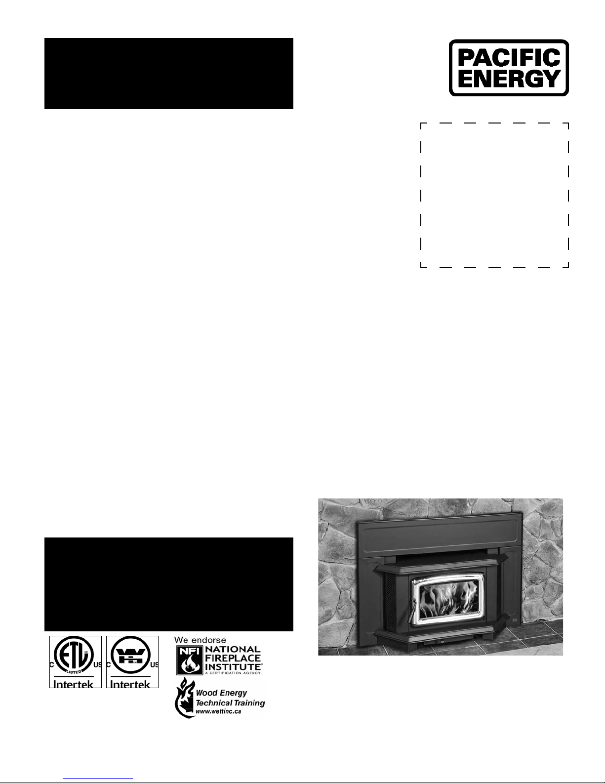
Summit
Wood Insert
INSTALLATION
AND OPERATING
INSTRUCTIONS
190112-24 SINB.BODY 5055.5112
MODEL:
SUMMIT INSERT
SERIES - B

NOTE:
WE STRONGLY
RECOMMEND THAT
SMOKE DETECTORS BE
INSTALLED.
If smoke detectors have been previously installed, you may notice that
they are operating more frequently.
This may be due to curing of stove
paint or fumes caused by accidentally
leaving the re door open. Do not
disconnect the detectors. If necessary, relocate them to reduce their
sensitivity.
SAFETY NOTICE:
If this stove is not
properly installed, a
house re may result.
For your safety, follow the installation
instructions. Contact
local building or re
officials about restrictions and installation
inspection requirements in your area.
Please read this entire manual before
you install and use your new room
heater. Failure to follow instructions
may result in property damage, bodily
injury, or even death.
Contents
Safety ............................................................................................ 3
Clearances ................................................................................... 3
Masonry or Factory Built Fireplace ........................................................ 3
Mantel Clearances ................................................................................. 5
Dimensions .................................................................................. 5
Installation .................................................................................... 6
Fireplace Speci cations ......................................................................... 6
Into a Masonry Fireplace ....................................................................... 6
Full Flue Liner - (Required in Canada) .................................................. 7
Direct Flue Connection .......................................................................... 7
Into a Factory Built Fireplace ................................................................. 8
Combustion Air ...................................................................................... 8
Surround Assembly and Installation ...................................................... 9
Fan Speed Controller Relocation ..........................................................11
Operation .................................................................................... 13
Wood Selection.....................................................................................13
How to Test Your Wood .........................................................................13
Lighting the Fire ....................................................................................13
Normal Operation .................................................................................13
Restarting After Extended or Overnight Burns ......................................13
More Wood, More Heat .........................................................................14
Proper Draft ..........................................................................................14
Ash Removal ........................................................................................14
Disposal of Ashes .................................................................................14
Blower ......................................................................................... 14
Blower Operation ..................................................................................14
Electrical Supply ...................................................................................14
Creosote ..................................................................................... 15
Formation and Need for Removal .........................................................15
Chimney Fires .......................................................................................15
In Case of a Chimney Fire ....................................................................15
Avoiding a Chimney Fire .......................................................................15
Maintenance ............................................................................... 16
Baffle Removal ......................................................................................16
Appendix A ................................................................................. 17
Understanding & Operating Your Paci c Energy Stove .........................17
Troubleshooting ....................................................................................18
Firebrick Installation .................................................................. 19
Replacement Parts .................................................................... 20
Label .................................................................................................... 23
2 SINB.BODY 190112-24
”
Safety
Clearances
Please read this entire manual before installation
and use of this wood burning insert. Failure to follow
these instructions could result in property damage,
bodily injury or even death.
We strongly recommend that smoke detectors be installed.
If smoke detectors have been previously installed, you may
notice that they are operating more frequently. This may be
due to curing of stove paint or fumes caused by accidentally
leaving the re door open. Do not disconnect the detectors.
If necessary, relocate them to reduce their sensitivity.
SAFETY NOTICE: If this stove is not properly installed, a
house re may result. For your safety, follow the installation directions. Consult local building or re officials
about restrictions and installation inspection requirements in your area.
NATIONAL
FIREPLACE
INSTITUTE
CERTIFIED
www.nficertified.org
We recommend that our products be
installed and serviced by professionals
who are certified in the U.S. by the
National Fireplace Institute (NFI)
or in Canada by Wood
Energy Technical
Training (WETT)
Wood Energy
Technical Training
www.wettinc.ca
Masonry or Factory Built Fireplace
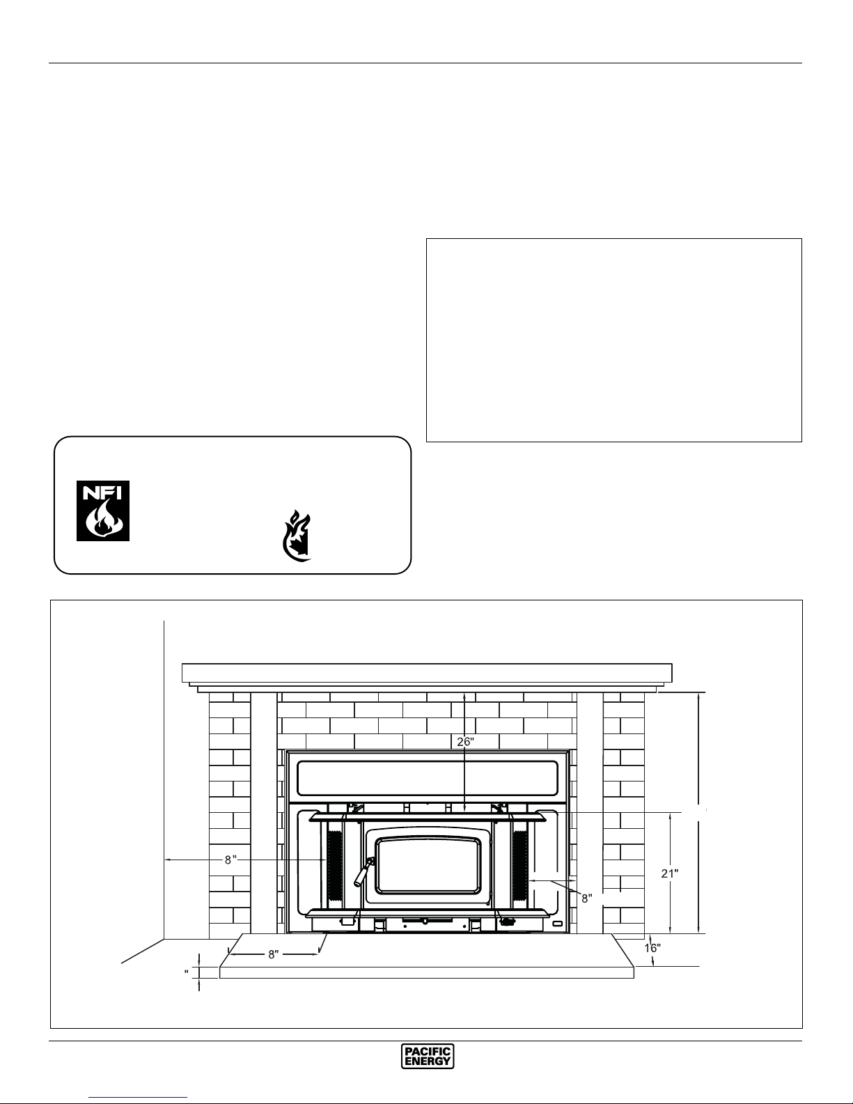
The minimum required clearances to surrounding combustible materials when installed into a masonry or factory built
replace are listed below and in gure #1.
Minimum Clearances to Combustibles
(Measured From Insert Body)
Adjacent Sidewall ..........................8 in. (203 mm.)
Mantel ..........................................26 in. (660 mm.)
12" Mantel with Shield .................20 in. (508 mm.)
(with part # SINB.MSMBKA)
Top Facing ................................... 26 in. (660 mm.)
with Mantel Shield .......................20 in. (508mm)
(with part # SINB.MSMBKA)
Side Facing (1.5 in. extension) ...... 8 in. (203 mm.)
CAUTION: Unit hot while in operation. Parts of the appliance, especially the external surfaces, will be hot to touch
when in operation. Keep children, clothing and furniture
away. Contact may cause skin burns.
Fig. # 1
Adjacent Wall
Mantel or Top Facing
Side Facing
47
Fireplace
Hearth
3
SINB.BODY 190112-24 3
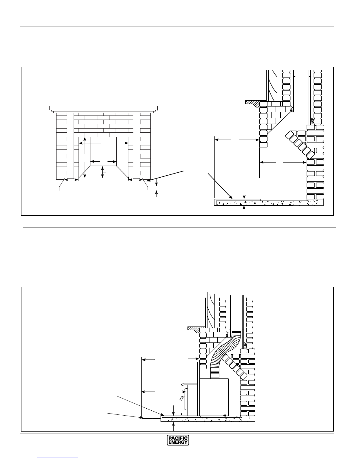
Fireplace hearth requirements: (Measured without the insert)
The non-combustible replace hearth must be raised 3” above an adjacent combustible oor and extend 16” in front and
*
8” beyond each side of the existing replace opening. A non-combustible hearth that extends a minimum 20-1/2” in front
of the replace opening may be ush to an adjacent combustible oor.
MINIMUM FIREPLACE
OPENING AND HEARTH
DIMENSIONS
16”
18”
23 1/8”
28”
26”
18”
Non-combustible replace
hearth
8”8”
3”
*
3”
Ember protection:
Combustible oor in front of the replace insert must be protected from hot embers by non-combustible material extend-
**
ing 16” (USA) and 18” (CANADA) to the ring side and 8” to other sides of the unit.
Consult CAN/CSA-B365 Installation Code for Solid-Fuel-Burning appliances and equipment in Canada, and N.F.P.A.
211 Standard for chimneys, replaces, vents and Solid-Fuel-Burning appliances in USA.
MINIMUM EMBER
PROTECTION
DIMENSIONS
Non-combustible hearth
Non-combustible oor
covering
4 SINB.BODY 190112-24
22 1/2” USA
24 1/2” CANADA
16” USA
**
18” CANADA
3”
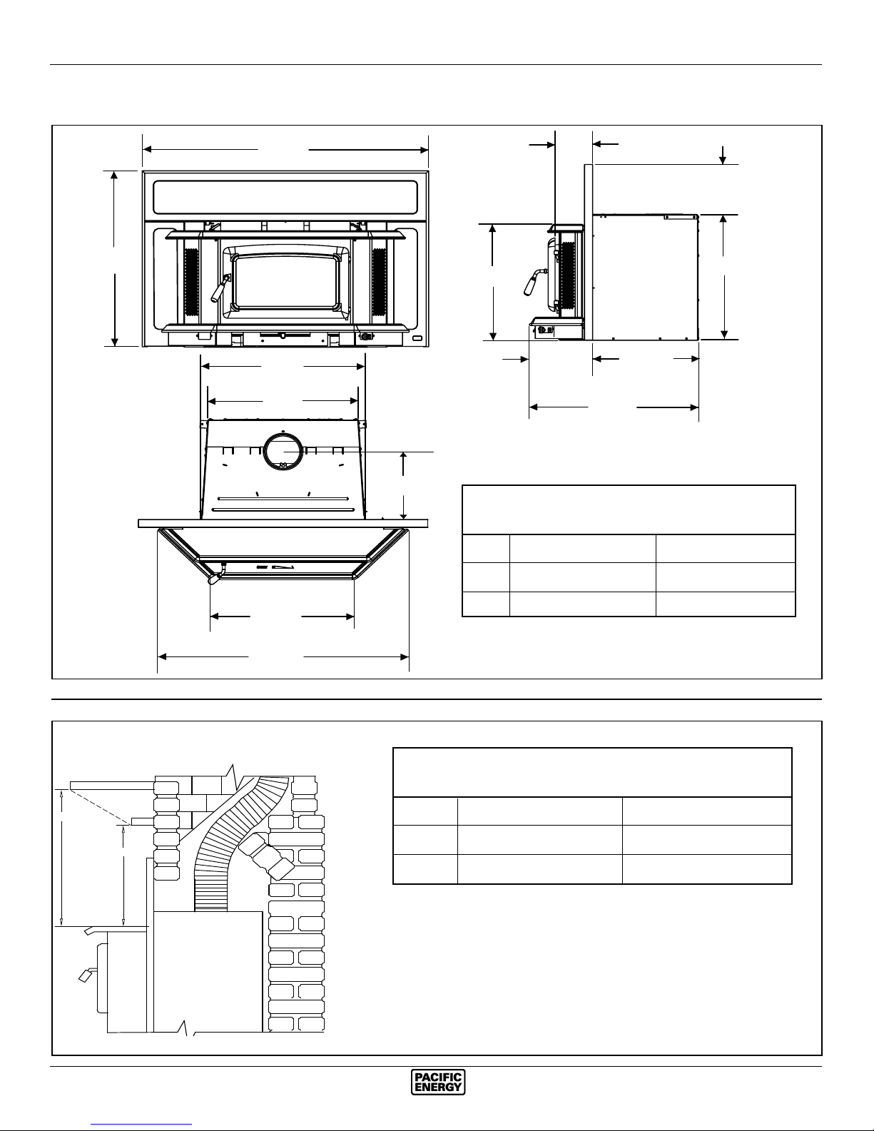
Dimensions
B
A
27 9/16”
25 3/8”
12 1/4”
6 5/8”
9 1/8”
21”
10 7/8”
18”
28 7/8”
22 15/16”
SURROUND DIMENSIONS
REG. SURROUND O/S SURROUND
Mantel Clearances
12"
A
4"
B
23 5/16”
40 7/8”
A 48 3/4” 52 3/4"
B 32 1/16” 34 1/16"
MANTEL CLEARANCE
CHART
WITHOUT SHIELD WITH SHIELD
A 26” 20"
B 23 1/2” 18"
SINB.BODY 190112-24 5
Installation
Your Insert is designed to be installed into a masonry or factory built zero-clearance replace. The masonry replace
must be built according to the requirements of the Standard
of Chimneys, Fireplaces, Vents and Solid Fuel Burning appliances, N.F.P.A. 211 (Latest Edition) or applicable National,
Provincial, State or local codes. The installation shall conform
to CAN/CSA-B365, Installation Code for Solid-Fuel-Burning
Appliances and Equipment. The factory built zero-clearance
replace and its chimney must be listed per UL 127 or ULC
S610 standards.
Warning: Under no circumstances is this heater to be installed
in a makeshift or "temporary" manner.
DO NOT CONNECT THIS UNIT TO A CHIMNEY FLUE
SERVICING ANOTHER APPLIANCE.
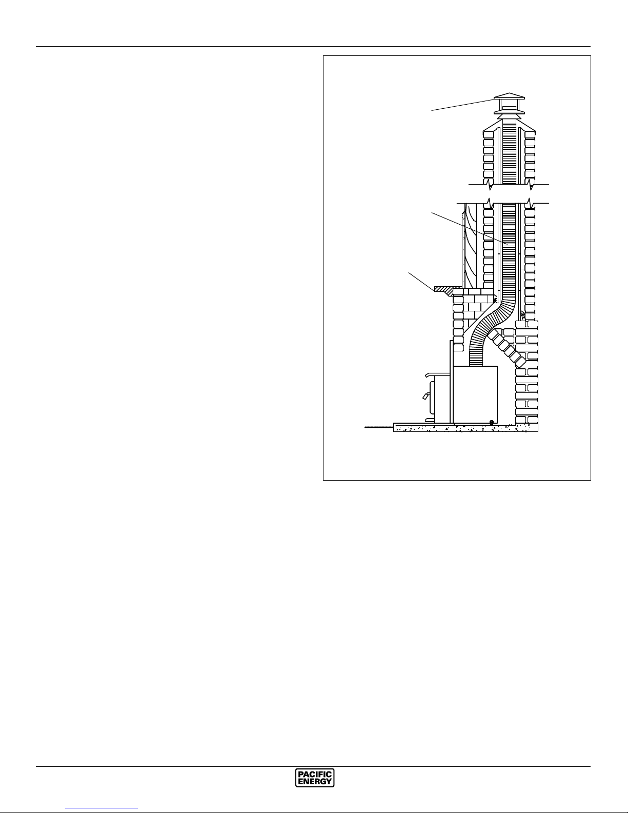
Fig. # 2
Stainless Steel
Rigid or Flex Liner
Full Flue Liner
Rain Cap
Fireplace Speci cations
Your replace is required to have the following minimum
sizes:
WIDTH (at front) 28" (711 mm)
WIDTH (at rear) 26" (660 mm)
HEIGHT 23-1/8" (587 mm)
DEPTH 18" (457 mm)
Chimney height 15' (minimum).
A metal tag is provided and is to be fastened to the back
wall of the replace, if the replace has been modi ed
to accommodate the insert.
Into a Masonry Fireplace
Inspect your replace for cracks, loose mortar or other physical defects. If repairs are required, they should be completed
before installing your insert.
The replace chimney must be suitable for wood burning use.
Check for creosote build up or other obstructions, especially if
it has not been in use for some time. Have chimney swept.
The existing replace damper is to be locked open or removed
completely.
WARNING: Do not remove bricks or mortar from your
existing replace.
Exception: Masonry or steel, including the damper plate,
may be removed from the smoke shelf and adjacent damper
frame if necessary to accommodate a chimney liner, provided
that their removal will not weaken the structure of the replace
and chimney, and will not reduce protection for combustible
materials to less than that required by the National Building
Code.
Mantel or
Top Facing
Positive Flue Connection(In U.S.A. only): where a throat
blocker plate and a short connector pipe is used.
Note: A clean-out door may be required under local codes,
when a positive ue connection is used. Consult local
codes.
Paci c Energy highly recommends the use of a full
liner as the safest installation and providing optimum
performance. When connected to a full liner, the Insert
is able to draft correctly and will prevent problems such
as difficult start-ups and smoking out the door.
The Insert must be installed in accordance with local and or
national building codes. The two methods of ue connection
that are acceptable in most areas are:
Full Flue Liner: (Fig.2, Required in Canada) where a stainless
steel rigid or exible liner extends from the Insert ue collar
to the top of the chimney.
6 SINB.BODY 190112-24
Full Flue Liner - (Required in Canada)
1) Measure the chimney height from the top of the existing
ue to the oor of the hearth. This will allow extra length
of liner for ashing and rain cap.
2) Feed the stainless steel liner from top of the chimney,
through the damper area and into the replace cavity.
Attach a stove connector to the bottom of the liner.
3) Remove bay top and both right & left blower covers
(Fig #4 & 6).
4) Remove casing top by removing screws on each casing
side and pulling top forward(Fig. #5).
5) Push insert into replace. Use the rear adjustment legs to
level insert. (NOTE: Adjustment legs are located in bottom
rear of insert)
6) Measure, trim and shape a top ashing to t the existing
chimney ue. Plan for a 1” to 1-1/2” overlap on each side.
Place ashing over top of the liner and seat rmly against
the tile.
7) Caulk around liner with high temp stove cement and insert
into collar. Screw in fasteners to secure.
8) Attach a rain cap to the end of the liner. A storm collar
may be used if desired.
9) Reattach casing top with screws previously removed.
Consult your local Dealer about relining your replace
chimney.
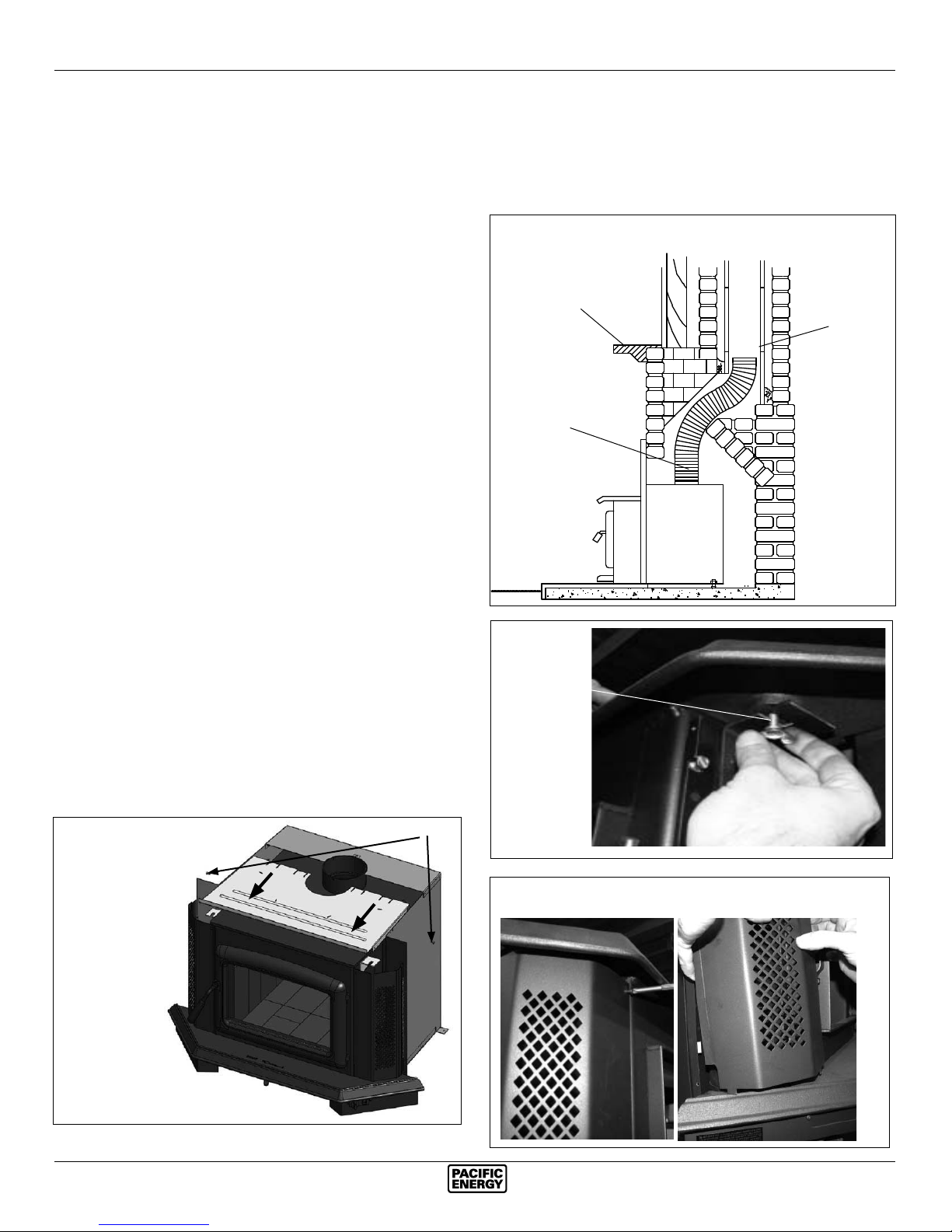
Direct Flue Connection (USA only)
Fig. # 3
Mantel or
Top Facing
6" Stainless Steel
Rigid or Flex Liner
Direct Flue Connection
Chimney
Flue Liner
1) Measure from the rst chimney ue liner tile to the top of
the Insert. Allow extra length of liner to insert into ue
tile.
2) Feed the stainless steel liner through the damper area
and into the rst chimney ue tile. Seal around pipe.
Note: A clean-out door may be required under local codes,
when a direct ue connection is used. Consult local codes.
3) Remove bay top and both right & left blower covers
(Fig #4 & 6).
4) Remove casing top by removing screws on side and pulling top forward(Fig. #5).
5) Push insert into replace. Use the rear adjustment legs
to level insert.
6) Attach connector pipe to stove collar.
7) Reattach casing top and fasten.
Fig. # 5
SCREWS
Fig. # 4
“Wing” Screw
Fig. #6
SINB.BODY 190112-24 7
Into a Factory Built Fireplace
Your Insert may be installed into a factory built replace (size
permitting) with the following requirements:
1) Inspect your replace for damage or other physical defects. The replace must be in good working condition.
If in doubt about its condition, seek professional advice.
Check for creosote build up or other obstructions inside
the chimney, especially if it has not been in use for some
time. Before installing, clean your chimney system thoroughly.
2) A full stainless steel rigid or exible ue liner meeting
type HT requirements (2100°F) per UL1777 (U.S.) or
ULC S635 (Canada) must be used for both safety and
performance. The liner must be securely attached to the
Insert ue collar and the chimney top.
3) The surround must be sealed to the replace front or the
damper area around the chimney liner must be sealed
to prevent room air entering the chimney cavity of the
replace.
4) The air ow within and around the replace must not be
altered by the installation of the Insert (i.e. no blockage of
louvers or cooling air inlet or outlet ports). This includes
the circulating air chambers in a steel replace or metal
heat circulator.
5) Alteration of the replace in any manner is not permitted
with the following exceptions:
a: external trim pieces which do not affect the operation
of the replace may be removed and stored on or within
the replace for re-assembly if the Insert is removed.
b: the chimney damper may be removed to install the
liner.
Combustion Air
Consult local building codes regarding combustion air supply. Intake or combustion air can be supplied to the Insert in
one of two ways:
1) Outside air supply: Remove cover from ash clean out in
existing replace. Place a rodent screen in place of the
cover. Install the Insert as described in the "Installation"
section, making sure not to cover the opening of the air
inlet. When installation is complete, seal surround to replace and anywhere else air may enter. This will ensure
combustion air is drawn from outside the house and into
the 9" x 2" intake at the lower rear of the appliance.
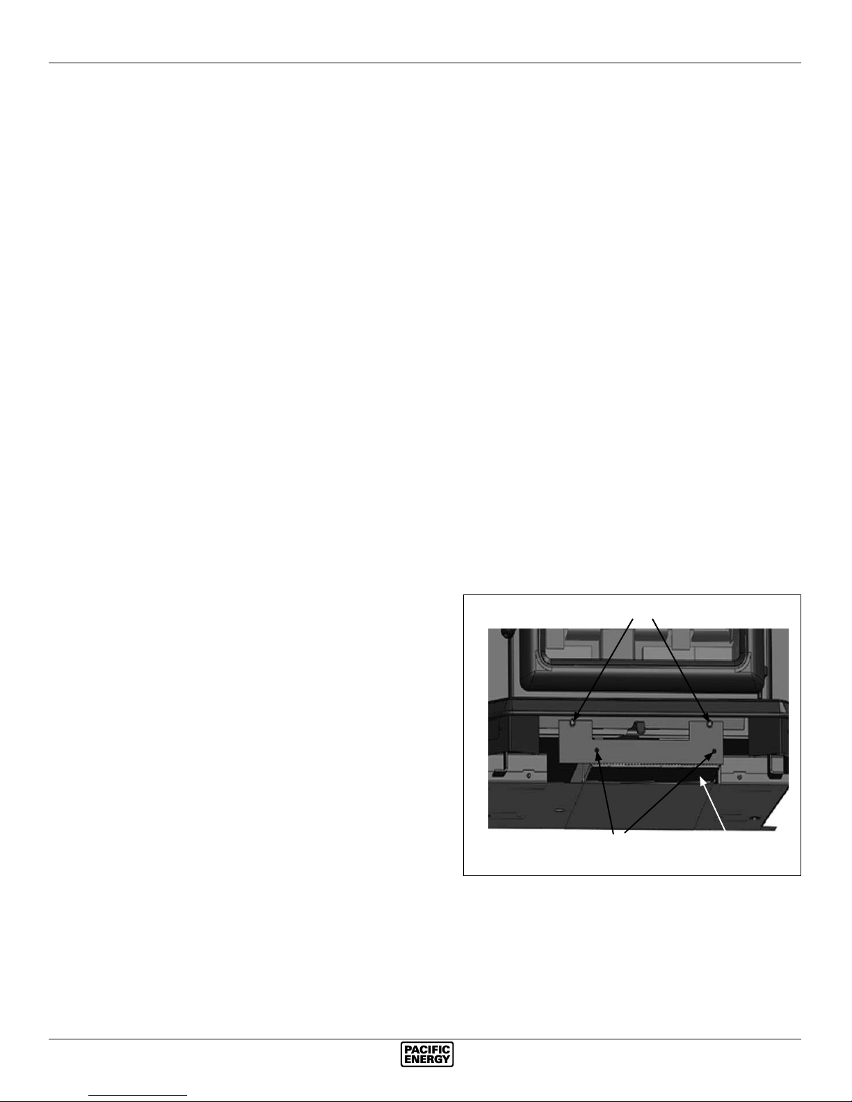
2) Room air supply: Loosen the two hex head bolts slightly
(DO NOT REMOVE) Remove the two screws in the cover
plate and remove, slide the cover box out and discard. Replace cover plate and tighten hex head bolts. Fig. #7).
Fig. # 7
HEX HEAD BOLTS
SCREWS
COVER
BOX
8 SINB.BODY 190112-24
 Loading...