

Pacific energy SPND.BODYB Installation And Operating Instructions Manual
IMPORTANT:
THESE INSTRUCTIONS ARE TO
REMAIN WITH THE HOMEOWNER
SAVE THESE INSTRUCTIONS
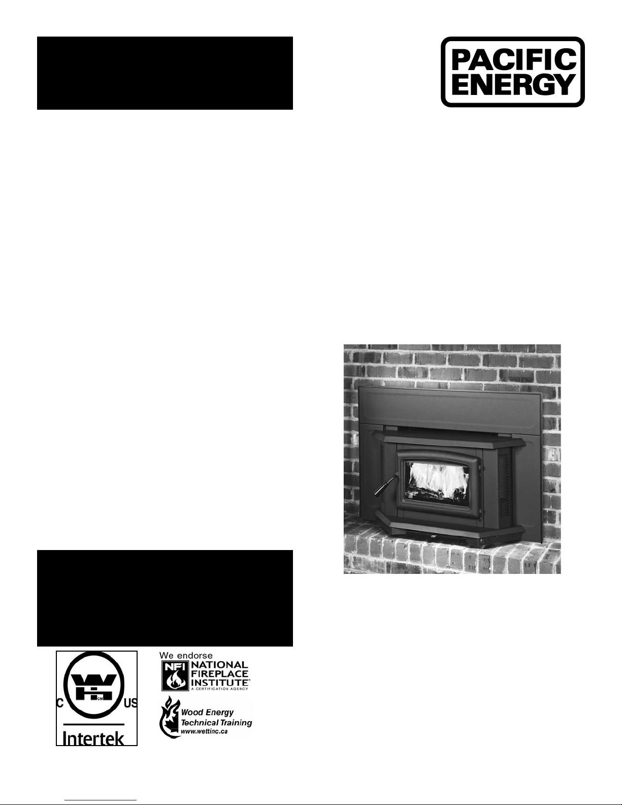
Super Insert
SAFETY NOTICE
If this stove is not properly installed, a house
re may result. For your safety, follow the
installation directions. Consult local building
inspector or officials about restrictions and
installation inspection requirements in your
area.
INSTALLATION
AND OPERATING
INSTRUCTIONS
TESTED and LISTED
to ULC S628 / UL 1482
Meets the U.S. Environmental Protection
Agency's July 1990 Particulate Emission
Standards
100610-24 SPND.BODYB 5055.101.B
MODEL:
SUPER INSERT
DESIGN-D
SPND.BODYB

Contents
Safety ................................................................................................. 3
Clearances ......................................................................................... 3
Masonry or Factory Built Fireplace ............................................ 3
Dimensions ........................................................................................ 5
Installation .......................................................................................... 6
Fireplace Speci cations ............................................................. 6
Into a Masonry Fireplace ........................................................... 6
Full Flue Liner (Required in Canada) Fig #2 ..............................7
Direct Flue Connection (Only permitted in USA) Fig #4 ............. 7
Into a Factory Built Fireplace ..................................................... 7
Fan Speed Controller Relocation ...............................................8
Surround Assembly and Installation ...........................................10
Combustion Air ........................................................................... 12
Operation ........................................................................................... 13
Wood Selection .......................................................................... 13
How to Test Your Wood ..............................................................13
Lighting the Fire ......................................................................... 13
Normal Operation ...................................................................... 13
Restarting After Extended or Overnight Burns ...........................13
More Wood, More Heat .............................................................. 14
Proper Draft ................................................................................ 14
Ash Removal .............................................................................. 14
Disposal of Ashes ...................................................................... 14
Blower ................................................................................................ 14
Blower Operation ....................................................................... 14
Electrical Supply ........................................................................ 14
Creosote ............................................................................................15
Formation and Need for Removal ..............................................15
Chimney Fires ............................................................................15
In Case of a Chimney Fire ......................................................... 15
Avoiding a Chimney Fire ............................................................ 15
Maintenance ......................................................................................16
Baffle Removal ........................................................................... 16
Replacement Parts ............................................................................ 17
Appendix A .........................................................................................18
Understanding & Operating Your Paci c Energy Stove .............. 18
Troubleshooting ..........................................................................19
Firebrick Installation ........................................................................... 20
Label .......................................................................................... 23
2
SPND.BODYB 100610-24
6.5"
30"
20.5"
2"
16"
21"
with mantle shield
Safety
Clearances
READ ALL INSTRUCTIONS BEFORE INSTALLING AND USING
THIS APPLIANCE.
We strongly recommend that smoke detectors be installed. If
smoke detectors have been previously installed, you may notice
that they are operating more frequently. This may be due to curing
of stove paint or fumes caused by accidentally leaving the re
door open. Do not disconnect the detectors. If necessar y, relocate
them to reduce their sensitivity.
SAFETY NOTICE: If this stove is not properly installed, a house
re may result. For your safety, follow the installation directions.
Consult local building or re officials about restrictions and
installation inspection requirements in your area.
NATIONAL
FIREPLACE
INSTITUTE
CERTIFIED
www.nficertified.org
We recommend that our products be
installed and serviced by professionals
who are certified in the U.S. by the
National Fireplace Institute (NFI)
or in Canada by Wood
Energy Technical
Training (WETT)
Wood Energy
Technical Training
www.wettinc.ca
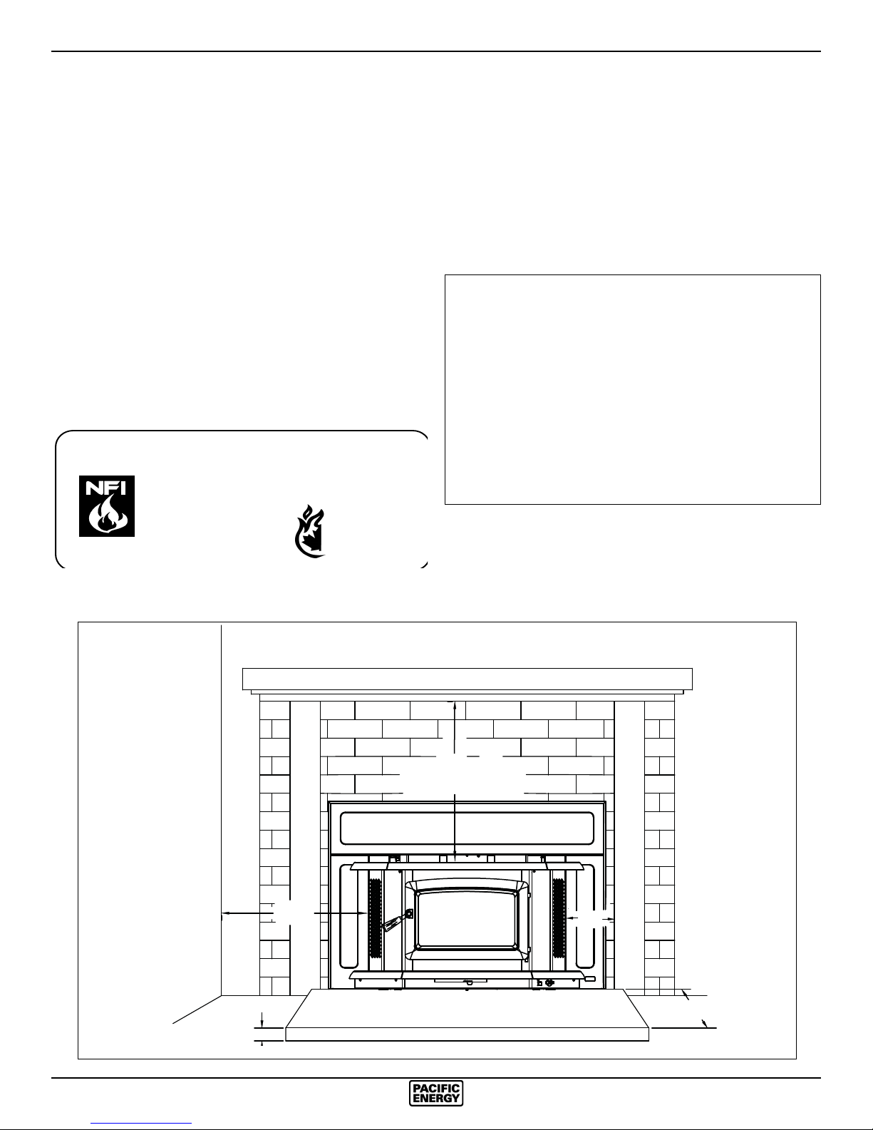
Masonry or Factory Built Fireplace
The minimum required clearances to surrounding combustible
materials when installed into a masonry or factory built replace
are listed below and in gure #1.
Minimum Clearances to Combustibles
(Measured From Insert Body)
Adjacent Sidewall ..................... 20.5 in. (520 mm.)
Mantel ..........................................30 in. (762 mm.)
Mantel with Shield .......................21 in. (508 mm.)
(with part # SPND.MSMBKA)
Top Facing ................................... 30 in. (762 mm.)
with Mantel Shield .......................21 in. (508mm)
(with part # SPND.MSMBKA)
Side Facing (1.5 in. extension) ... 6.5 in. (165 mm.)
Fig. # 1
Adjacent Wall
Mantel or Top Facing
Fireplace
Hearth
Side Facing
SPND.BODYB 100610-24
3
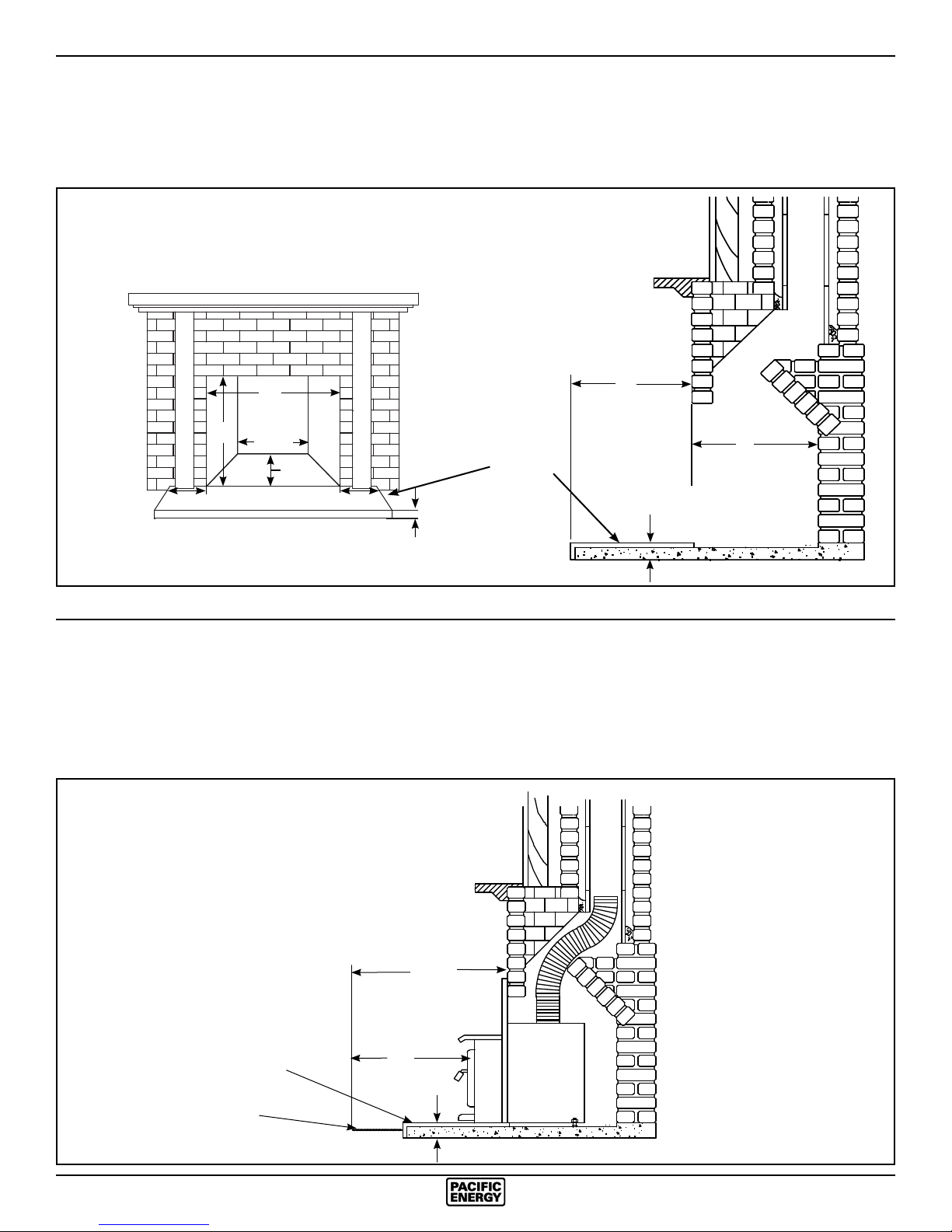
Fireplace hearth requirements: (Measured without the insert)
The non-combustible replace hearth must be raised 2” above an adjacent combustible oor and extend 16” in front and 8” beyond
*
each side of the existing replace opening. A non-combustible hearth that extends a minimum 23-1/2” in front of the replace
opening may be ush to an adjacent combustible oor.
MINIMUM FIREPLACE
OPENING AND HEARTH
DIMENSIONS
16”
18”
21”
24”
21 3/4”
18”
Non-combustible replace
hearth
8”8”
2”
*
2”
Ember protection:
Combustible oor in front of the replace insert must be protected from hot embers by non-combustible material extending
**
16” to the ring side and 8” to other sides of the unit.
Consult CAN/CSA-B365 Installation Code for Solid-Fuel-Burning appliances and equipment in Canada, and N.F.P.A. 211
Standard for chimneys, replaces, vents and Solid-Fuel-Burning appliances in USA.
MINIMUM EMBER
PROTECTION
DIMENSIONS
Non-combustible replace
hearth
Non-combustible oor
covering
4
22 1/2”
16”
**
2”
SPND.BODYB 100610-24
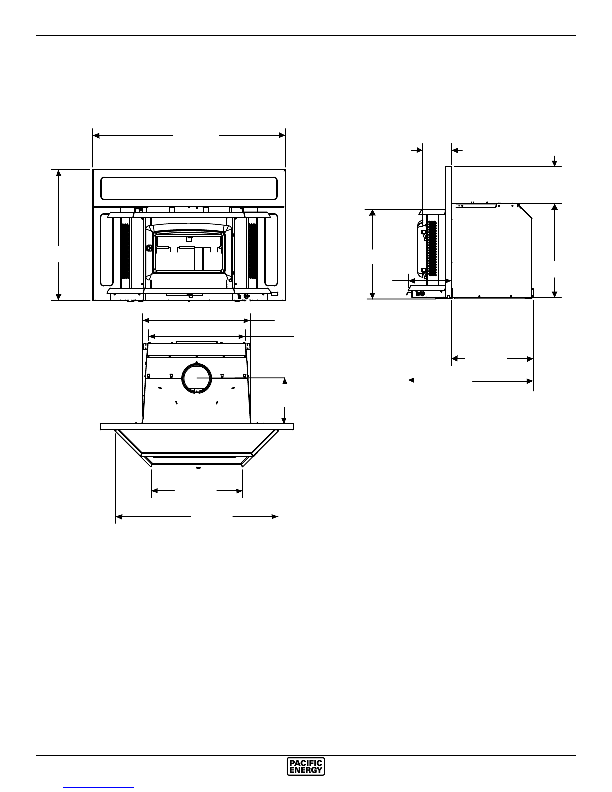
Dimensions
42 5/8”
6 1/2”
8 1/8”
28 7/8”
21 1/8”
36”
23 3/4”
10”
21 1/2”
19 9/16”
9 1/2”
20 3/4”
18”
28 1/8”
SPND.BODYB 100610-24
5
Installation
Your Insert is designed to be installed into a masonry or factorybuilt, zero-clearance replace. The masonry replace must be
built according to the requirements of the Standard of Chimneys,
Fireplaces, Vents and Solid Fuel Burning appliances, N.F.P.A.
211 (Latest Edition) or applicable National, Provincial, State or
local codes. The installation shall conform to CAN/CSA-B365,
Installation Code for Solid-Fuel-Burning Appliances and
Equipment. The factory-built, zero-clearance replace and its
chimney must be listed per UL 127 or ULC S610 standards.
Warning: Under no circumstances is this heater to be installed
in a makeshift or "temporary" manner.
DO NOT CONNECT THIS UNIT TO A CHIMNEY FLUE
SERVICING ANOTHER APPLIANCE.
Fireplace Speci cations
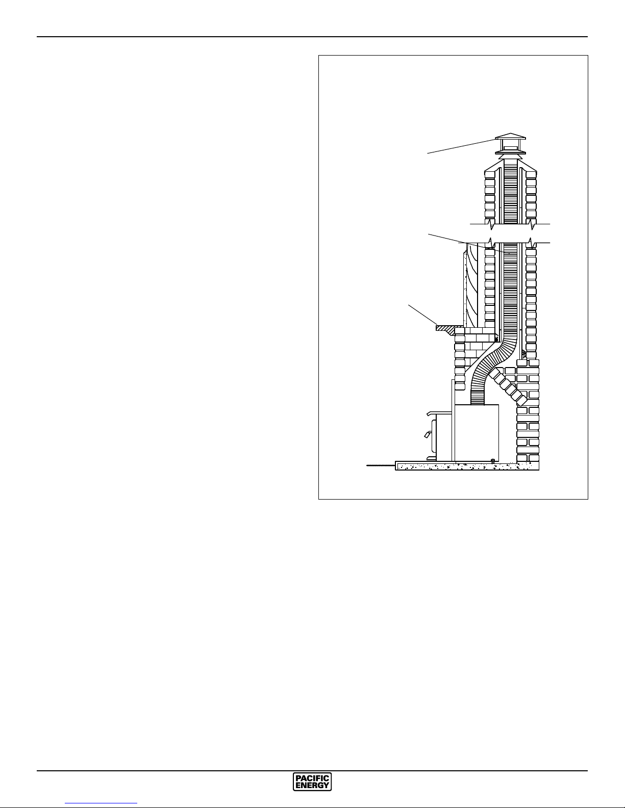
Fig. # 2
Full Flue Liner
(Required in Canada)
Rain Cap
Stainless Steel
Rigid or Flex Liner
Your replace is required to have the following minimum sizes:
WIDTH (at front) 23 3/4" (602.44 mm)
WIDTH (at rear) 21-3/4" (552.5 mm)
HEIGHT 21" (533.4 mm)
DEPTH 18" (457.2 mm)
Chimney height 15' (minimum)
A metal tag is provided and is to be fastened to the back
wall of the replace, if the replace has been modi ed to
accommodate the insert.
Into a Masonry Fireplace
Inspect your replace for cracks, loose mortar or other physical
defects. If repairs are required, they should be completed before
installing your insert.
The replace chimney must be suitable for wood burning use.
Check for creosote build up or other obstructions, especially if it
has not been in use for some time.
The existing replace damper is to be locked open or removed
completely.
WARNING: Do not remove bricks or mortar from your existing
replace.
Exception: Masonry or steel, including the damper plate, may
be removed from the smoke shelf and adjacent damper frame if
necessary to accommodate a chimney liner, provided that their
removal will not weaken the structure of the replace and chimney,
and will not reduce protection for combustible materials to less
than that required by the National Building Code.
The Insert must be installed in accordance with local and or
national building codes. The two methods of ue connection that
are acceptable in most areas are:
Mantel or
Top Facing
Full Flue Liner: (Fig.2) where a stainless steel rigid or exible liner
extends from the Insert ue collar to the top of the chimney.
Positive Flue Connection: where a throat blocker plate and a
short connector pipe is used.
Note: A clean-out door may be required under local codes,
when a positive ue connection is used. Consult local codes.
Paci c Energy highly recommends the use of a full liner as
the safest installation and providing optimum performance.
When connected to a full liner, the Insert is able to draft
correctly and will prevent problems such as difficult startups and smoking out the door.
For difficult installations, this insert is approved for use with
a SPND.3OFFSETA - 3” ue offset box. Only this offset box is
approved for use with this insert. The use of any other offset
box may cause a hazard and/ or void any warranty.
6
SPND.BODYB 100610-24
Full Flue Liner (Required in Canada) Fig #2
This replace insert must be installed with a continuous liner
of 6” diameter extending from the replace insert to the top of
the chimney. The chimney liner must conform to the class 3
requirements of CAN/ULC-S635, Standard for Lining systems
for Existing Masonry or Factory-Built Chimneys or Vents, or
CAN/ULC-S640, Standard for lining systems for New Masonry
Chimneys.
1) Measure the chimney height from the top of the existing ue
to the oor of the hearth. This will allow extra length of liner
for ashing and rain cap.
2) Feed the stainless steel liner from the top of the chimney,
through the damper area and into the replace cavity.
3) Attach a stove connector to the bottom of the liner, as per
the instructions provided with the chimney liner.
4) Push the Insert into position inside the replace and attach
the connector to the stove collar and secure with screws.
Use the rear adjusting legs to level the Insert.
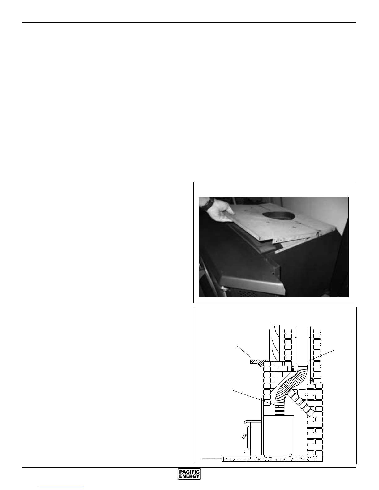
Note: For better access, the top of the casing may be removed
(Fig. #3). If it is necessary to get access to the connector
pipe through the ue outlet of the Insert, the baffle can be
removed (see Baffle Removal section).
5) Measure, trim and shape a top ashing to t the existing
chimney ue. Plan for a 1” to 1-1/2” overlap on each side.
Place ashing over top of the liner and seat rmly against
the tile.
6) Screw ashing collar to liner. Caulk gap around ashing with
RTV silicone.
7) Attach a rain cap to the end of the liner. A storm collar should
be used.
Consult your local Dealer about relining your fireplace
chimney.
especially if it has not been in use for some time. Before
installing, clean your chimney system thoroughly.
2) A full stainless steel rigid or exible ue liner meeting type
HT requirements (2100°F) per UL1777(U.S.) or ULC S635
(Canada) must be used for both safety and performance.
The liner must be securely attached to the insert ue collar
and the chimney top.
3) The surround must be sealed to the replace front or the damper
area around the chimney liner must be sealed to prevent room
air entering the chimney cavity of the replace.
4) The air ow within and around the replace must not be altered
by the installation of the Insert (i.e. no blockage of louvers or
cooling air inlet or outlet ports). This includes the circulating
air chambers in a steel replace or metal heat circulator.
5) Alteration of the replace in any manner is not permitted with
the following exceptions:
a: external trim pieces which do not affect the operation of
the replace may be removed and stored on or within the
replace for re-assembly if the Insert is removed.
b: the chimney damper may be removed to install the liner.
Fig. # 3
Direct Flue Connection (Only permitted in USA)
Fig #4
1) Measure from the rst chimney ue liner to the top of the
Insert. Allow extra length of liner to insert into ue tile.
2) Feed the stainless steel liner through the damper area and
into the rst chimney ue tile. Seal around pipe.
Note: A clean-out door may be required under local codes, when
a direct ue connection is used. Consult local codes.
3) Push the Insert into position inside the replace and attach
the connector pipe to the stove collar. Use the rear adjusting
legs to level the Insert.
Note: For better access, the top of the casing may be removed
(Fig. #3). If it is necessary to get access to the connector
pipe through the ue outlet of the Insert, the baffle can be
removed (see Baffle Removal section).
Into a Factory Built Fireplace
Your Paci c Insert may be installed into a factory built replace
with the following requirements:
1) Inspect your replace for damage or other physical defects.
The replace must be in good working condition. If in doubt
about its condition, seek professional advice. Check for
creosote build up or other obstructions inside the chimney,
Fig. # 4
Top Facing
6" Stainless Steel
Rigid or Flex Liner
Direct Flue Connection
(USA Only)
Mantel or
Chimney
Flue Liner
SPND.BODYB 100610-24
7
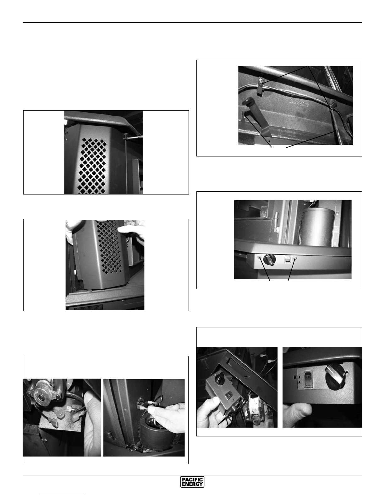
Fan Speed Controller Relocation
The fan speed controller is factory installed under the ash lip
on the right hand side. If required, it can be relocated to the left
side by following the instructions below. To make this as easy
as possible, it is suggested that this be done prior to tting the
surround and installation into the replace:
1) Remove the screw located at the top of the left and right
panels.
Fig. # 5
2) Lift up on each panel and remove. Set aside to prevent
damage.
4) Loosen the two bolts that secure the ash lip to the rebox,
carefully lift up the ash lip and remove from the rebox and
unscrew the wire support tabs.
Fig. # 8
BOLTS
5) Remove the two screws securing the speed controls assembly
to the ash lip. The cover plate on the opposite side can also
be removed at this time
Fig. # 9
SCREWS
Fig. # 6
3) Disconnect the wires from the fans (LHS & RHS) and
thermal snap switch. Take note of where the wires are routed
and secured. They must be positioned correctly to avoid
damage.
Fig. # 7
SCREWS
6) Remove the control assembly from the right hand side of the
ashlip. Flip it over and reattach on the left hand side of the
ashlip. Use the upper screw holes for best alignment.
Fig. # 10 Fig. # 11
`
8
SPND.BODYB 100610-24
 Loading...