

Pacific energy MIRAGE 30 A Installation And Operating Instructions Manual
INSTALLER:
Retain this manual for future reference.
Leave this manual with the appliance.
CONSUMER:
WARNING: If the information in these
instructions is not followed exactly a fire or
explosion may result causing property
damage, personal injury or death.
FOR YOUR SAFETY
Do not store or use gasoline or other
flammable vapours and liquids in the vicinity
of this or any other appliance.
WHAT TO DO IF YOU SMELL GAS
• Do not try to light any appliance.
• Do not touch any electrical switch.
• Do not use any phone in your building.
• Immediately call your gas supplier
from a neighbour’s phone. Follow the
gas supplier’s instructions.
• If you cannot reach your gas supplier
call the fire department.
SERIAL #
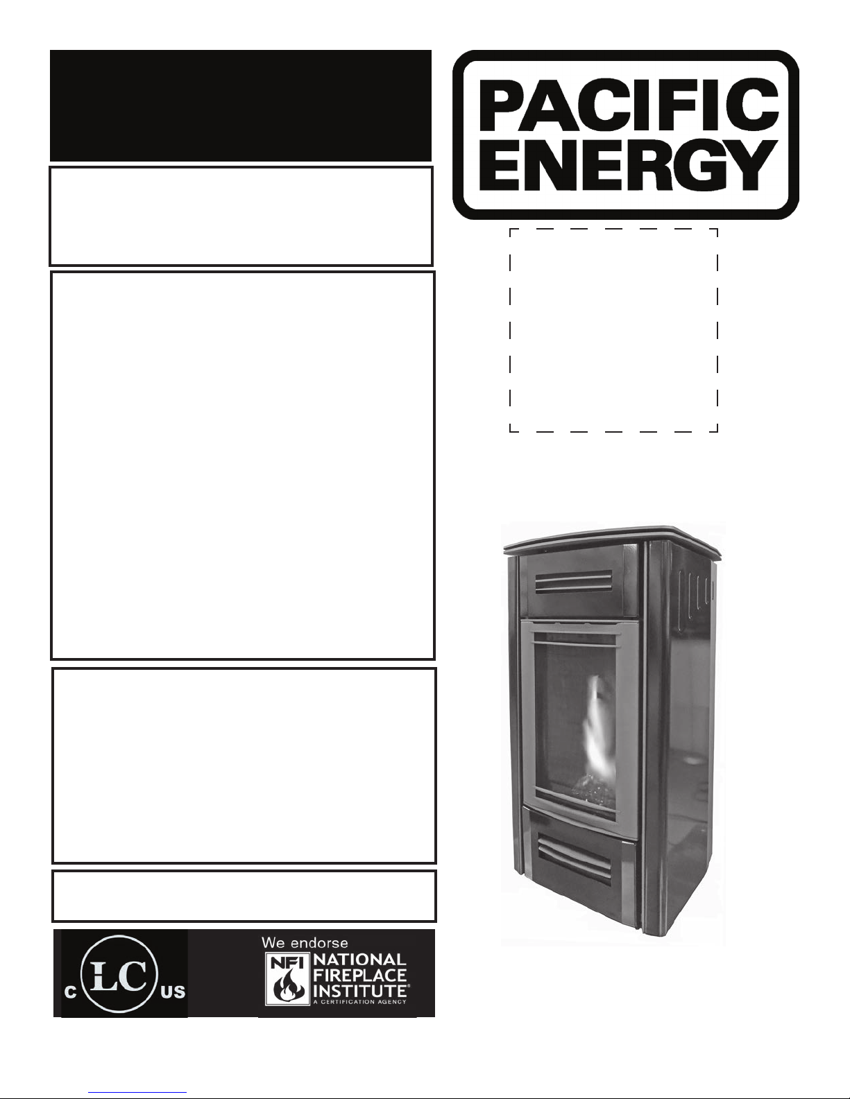
MIRAGE 30
INSTALLATION AND
OPERATING INSTRUCTIONS
Installation and service must be performed
by a qualified installer, service agency or the
gas supplier.
This appliance may be installed in an
aftermarket permanently located,
manufacture home (USA only) or mobile
home, where not prohibited by local codes.
This appliance is only for use with the type of
gas indicated on the rating plate. This
appliance is not convertible for use with
other gases unless a certified kit is used.
This appliance is suitable for installation in a
bedroom or bed sitting room.
MODEL: MIRAGE 30, SERIES: A
DIRECT VENT FREE STANDING
GAS STOVE
Visit www. pacificenergy.net for the most up-to-date version of this manual
180516-36
MR30
5055.MR30-A
Table of Contents
DANGER
Caution ...................................................................................... 3
Safety ......................................................................................... 3
Important Note for the Commonwealth of Massachusetts ....... 4
Mirage 30 Dimensions ................................................................ 5
Clearances to Combustibles ...................................................... 6
Locating the Stove ..................................................................... 6
Co-axial Venting ..........................................................................7
Co-Linear Venting ...................................................................... 8
Vent Terminal Minimum Clearances .......................................... 9
Venting Components ................................................................ 10
Gas and Electrical Connections ...............................................11
Gas connection .................................................................11
Electrical connection .........................................................11
Gas Supply ............................................................................... 12
Gas Pressure Check ................................................................ 12
Gas pressure requirements .............................................. 12
Gas Pressure Testing Procedure ............................................. 13
Pilot Adjustment ....................................................................... 13
Lighting Instructions ................................................................ 14
First Fire ................................................................................... 15
Special Operator Note ............................................................. 15
Remote Control Operation ...................................................... 15
Remote Transmitter Description .......................................17
IFC Module........................................................................17
Initializing the Fireplace for the rst time ..........................17
Temperature indication Display ........................................ 18
Turn on the Stove ............................................................. 18
Turn off the Stove ............................................................. 18
Manual Bypass of the Remote Control Transmitter ......... 18
Remote Flame Control ..................................................... 18
Room Thermostat (Transmitter Operation) ...................... 19
Smart Thermostat (Transmitter Operation) ...................... 19
Comfort Fan Speed Control ............................................. 19
Continuous Pilot/Intermittent Pilot (CPI/IPI) selection ..... 20
Key Lock .......................................................................... 20
Low Battery Power Detection .......................................... 20
Maintenance .............................................................................21
Glass Door ........................................................................21
Annual Inspection ..............................................................21
Periodically ........................................................................21
Propane Conversion ................................................................ 22
Door Removal / Installation ..................................................... 23
Fan Removal / Installation ....................................................... 23
Firebox Panel Removal / Installation ....................................... 24
Burner Kit Installation/Removal ............................................... 25
Optional Media ........................................................................ 26
Removal ............................................................................27
Cladding Removal/Installation ..................................................27
Installation ........................................................................ 28
Air Adjustment ......................................................................... 29
Venturi adjustment ........................................................... 29
Air restrictor adjustment ................................................... 29
Replacement Parts ................................................................... 30
Wiring Diagram ..........................................................................31
Rating Label ............................................................................. 32
!
HOT GLASS WILL CAUSE
BURNS.
DO NOT TOUCH GLASS UNTIL
COOLED.
NEVER ALLOW CHILDREN TO
TOUCH GLASS.
This stove is equipped with a micro mesh safety screen for your
protection and must be installed with the unit. Removal of the
safety screen will cause the stove to become a burn hazard.
A barrier designed to reduce the risk of burns from the
hot viewing glass is provided with the appliance and
shall be installed for the protection of children and
other at-risk individuals.
5055.MR30-A
2
180516-36

Caution
FOR YOUR SAFETY - Do not install or operate your Pacic Energy gas stove
without rst reading and understanding this manual. Any installation or operational deviation from the following instructions voids the Pacic Energy ™
Warranty and may prove hazardous.
This appliance and its individual shut off valve must be disconnected from gas
supply piping system during any pressure testing of that system at test pressures in excess of 1/2 psig (3.5 kPa).
This appliance must be isolated from the gas supply piping system by closing
its individual manual shut off valve during any pressure testing of the gas supply piping system at test pressures equal to or less than 1/2 psig (3.5 kPa).
Note: When lit for the rst time, the appliance will emit a slight odour for a
couple of hours. This is due to the curing of paints, sealants and lubricants
used in the manufacturing process. This condition is temporary. Open doors
and windows to ventilate area. Smoke and fumes caused by the curing process
may cause discomfort to some individuals.
We recommend that our gas
hearth products be installed
and serviced by professionals
who are certied in the United
States by the National Fireplace
Do not use the gas stove if any part has been under water. Immediately call a
qualied service technician to inspect the gas stove and to replace any part of
the control system and any gas control which has been under water.
Institute® (NFI) as NFI Gas
Specialists
Safety
Due to high temperatures, this gas appliance should be located out of trafc and away from furniture and draperies.
Children and adults should be alerted to the hazards of high surface temperatures and should stay away to avoid burns
or clothing ignition.
Young children should be carefully supervised when they are in the same room as the appliance. Toddlers, young children, and others may be susceptible to accidental contact burns. A physical barrier is recommended if there are at-risk
individuals in the house. To restrict access to a replace or stove, install an adjustable safety gate to keep toddlers,
young children, and other at-risk individuals out of the room and away from hot surfaces. Clothing or other ammable
material should not be placed on or near the appliance.
Any grill, panel or door removed for servicing the unit must be replaced prior to operating. Failure to do so may create a
hazardous condition.
Installation and repair should be done by a qualied service person. The appliance should be inspected before use and
at least annually by a professional service person. More frequent cleaning may be required due to excessive lint from
carpeting, bedding material, etc. It is imperative that control compartments, burners and circulating air passageways of
the appliance be kept clean.
It is our policy that no responsibility is assumed by the Company or by any of its employees or representatives for any
damages caused by an inoperable, inadequate, or unsafe condition which is the result, either directly or indirectly, of any
improper operation or installation procedures.
This appliance must not be connected to a chimney ue serving a separate solid fuel burning appliance.
180516-36
3
5055.MR30-A

Important Note for the Commonwealth of Massachusetts
From Massachusetts Rules and Regulations 248 CMR 5.08:
(a) For all side wall horizontally vented gas fueled equipment installed in every dwelling, building or structure used in whole or in part for residential
purposes, including those owned or operated by the Commonwealth and where the side wall exhaust vent termination is less than seven (7) feet
above nished grade in the area of the venting, including but not limited to decks and porches, the following requirements shall be satised.
1. INSTALLATION OF CARBON MONOXIDE DETECTORS. At the time of installation of the side wall horizontal vented gas fueled equipment, the
installing plumber or gas tter shall observe that a hard wired carbon monoxide detector with an alarm and battery back-up is installed on the oor
level where the gas equipment is to be installed, in addition, the installing plumber or gas tter shall observe that a battery operated or hard-wired
carbon monoxide detector with an alarm is installed on each additional level of the dwelling, building or structure served by the side wall horizontal
vented gas fueled equipment. It shall be the responsibility of the property owner to secure the services of qualied licensed professionals for the
installation of hard-wired carbon monoxide detectors.
a. In the event that the side wall horizontally vented gas fueled equipment is installed in a crawl space or an attic, the hard-wired carbon monoxide
detector with alarm and battery back-up may be installed on the next adjacent oor level.
b. In the event that the requirements of this subdivision cannot be met at the time of completion of installation, the owner shall have a period of thirty
(30) days to comply with the above requirements; provided, however, that during said thirty (30) day period, a battery operated carbon monoxide
detector with an alarm shall be installed.
2. APPROVED CARBON MONOXIDE DETECTORS. Each carbon monoxide detector as required in accordance with the above provisions shall
comply with NFPA 720 and be ANSI/UL 2034 listed as IAS certied.
3. SIGNAGE. A metal or plastic identication plate shall be permanently mounted to the exterior of the building at a minimum height of eight (8) feet
above grade directly in line with the exhaust vent terminal for the horizontally vented gas fueled heating appliance or equipment. The sign shall
read, in print size no less than one-half (1/2) inch in size, “GAS VENT DIRECTLY BELOW. KEEP CLEAR OF ALL OBSTRUCTIONS”.
4. INSPECTION. The state or local gas inspector of the side wall horizontally vented gas fueled equipment shall not approve the installation unless,
upon inspection, the inspector observes carbon monoxide detectors and signage installed in accordance with the provisions of 248 CMR 5.089(2)
(a) 1 through 4.
(b) EXEMPTIONS. The following equipment is exempt from 248 CMR 5.089(2)(a) 1 through 4.
1. The equipment listed in Chapter 10 entitled “Equipment Not Required To Be Vented” in the most current edition of NFPA 54 as adopted by the
Board; and
2. Product Approved side wall horizontal vented gas fueled equipment installed in a room or structure separate from the dwelling, building or structure
used in whole or in part for residential purposes.
(c) MANUFACTURER REQUIREMENTS – GAS EQUIPMENT VENTING SYSTEM PROVIDED. When the manufacturer of Product Approved side wall
horizontally vented gas equipment provides a venting system design or venting system components with the equipment, the instructions provided
by the manufacturer for installation of the equipment and the venting system shall include:
1. Detailed instructions for the installation of the venting system design or the venting system components; and
2. A complete parts list for the venting system design or venting system.
(d) MANUFACTURER REQUIREMENTS – GAS EQUIPMENT VENTING SYSTEM NOT PROVIDED. When the manufacturer of a Product Approved
side wall horizontally vented gas fueled equipment does not provide the parts for venting the fuel gases, but identies “special venting systems”, the
following requirements shall be satised by the manufacturer.
1. The referenced “special venting system” instructions shall be included with the appliance or equipment installation instructions; and
2. The “special venting systems” shall be Product Approved by the Board, and the instructions for that system shall include a parts list and detailed
installation instructions.
(e) A copy of all installation instructions for all Product Approved side wall horizontally vented gas fueled equipment, all venting instructions, all parts
lists for venting instructions, and/or all venting design instructions shall remain with the appliance or equipment at the completion of the installation.
5055.MR30-A
4
180516-36
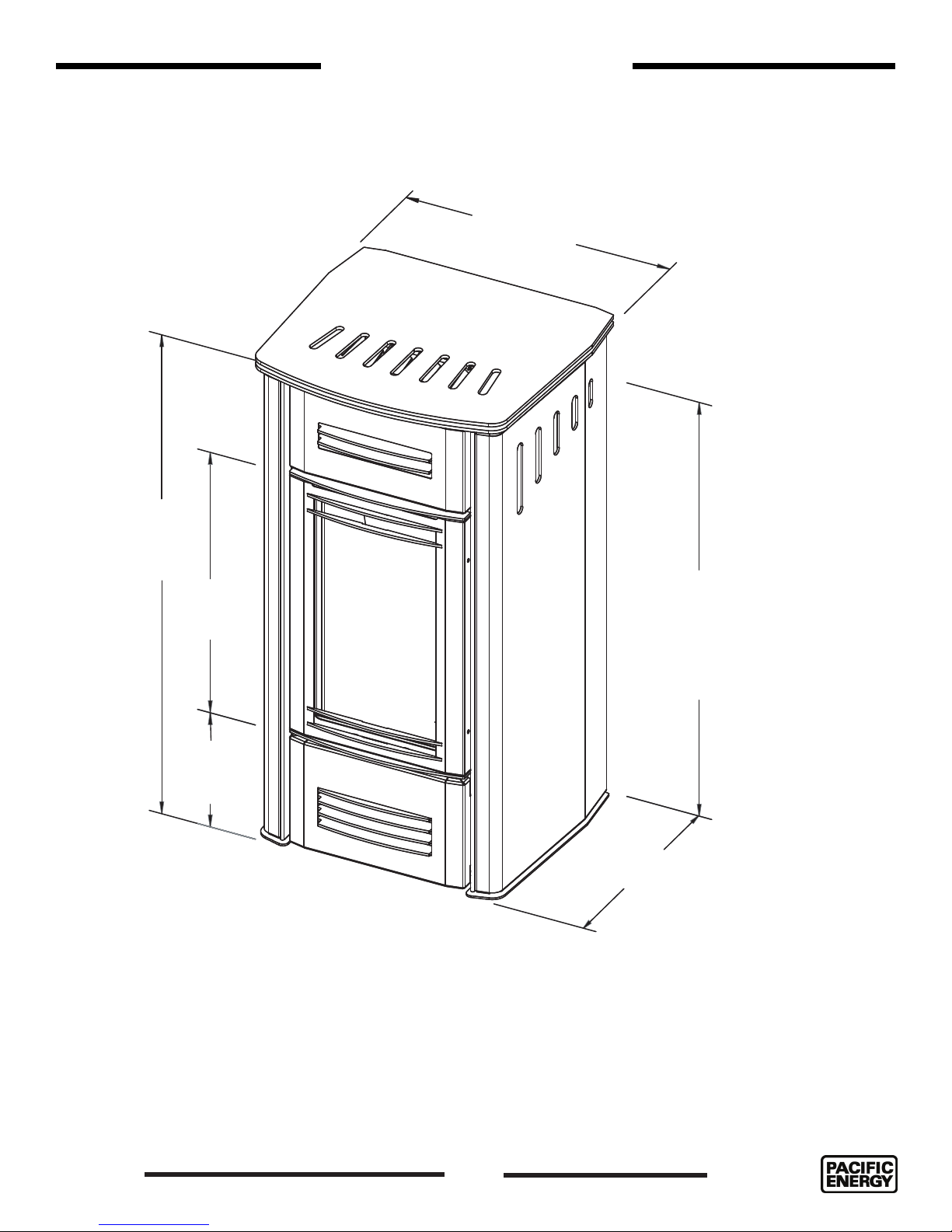
Mirage 30 Dimensions
27 7/16"
(646mm)
45 13/16"
26 3/8"
(670mm)
9 5/16"
(237mm)
40 1/8" (1019mm)
CENTER OF
VENTING
21 3/16"
(538mm)
Figure 1: Mirage 30 Dimensions.
180516-36
5
5055.MR30-A
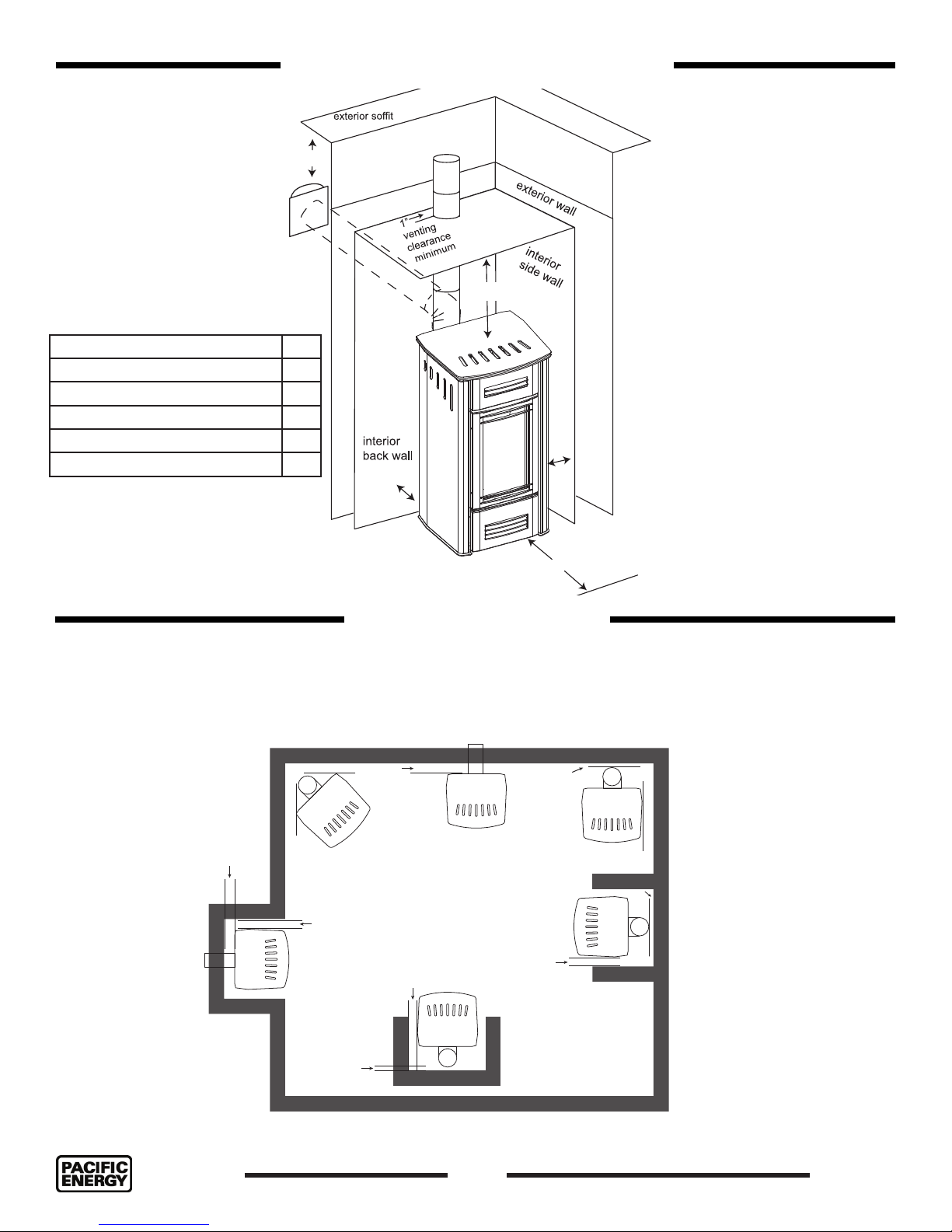
Clearances to Combustibles
Minimum Clearance to
Combustible Materials
INTERIOR SIDE WALL 4”
INTERIOR BACK WALL 4”
INTERIOR CEILING 36”
IN FRONT OF HEATER 36”
VENTING CLEARANCE 1”
EXTERIOR SOFFIT 30”
30”
Note on corner placement
Refer to minimum clearances
as shown in (Figure 3).
36”
Refer to page 7 for venting
allowances.
4”
4”
Figure 2: Mirage 30 clearance
front
36”
to combustibles.
Locating the Stove
In planning the installation for the stove, it is necessary to determine where the unit is to be installed, location
of vent system or a wall projection (Figure 3). Due to high temperatures, do not locate this stove in areas of
high trafc, near furniture or draperies. Also keep in mind that if the unit is positioned to its’ minimum clear-
ances as shown in (Figure 2), the unit may need to be moved in order to perform service, depending on the
nature of service to be performed.
4”
4”
4”
Vertical venting
4”
Horizontal venting
4”
4”
Horizontal venting
Vertical venting
1”
4”
Vertical venting
1”
Vertical venting
4”
Figure 3: Mirage 30 Common locations & minimum clearances.
5055.MR30-A
1”
6
180516-36
Co-axial Venting
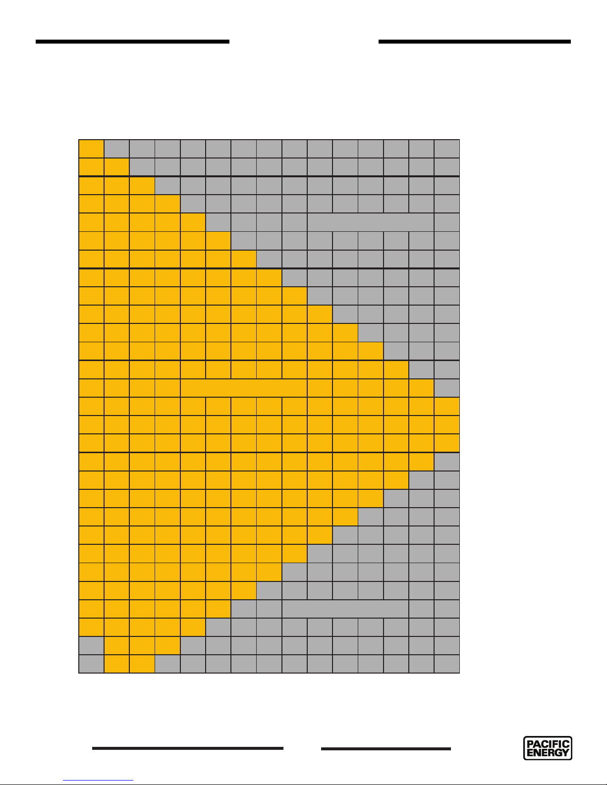
The Mirage 30 can be vented using co-axial components, or co-linear components for venting
through an existing replace and chimney. Maximum and minimum venting lengths can be found
on the venting charts - co-axial (Figure 4) & co-linear (Figure 5).
MIRAGE 18 / 30 CO-AXIAL VENTING CHART
28
27
26
Note: The vent must
not exceed a total
length of 28 feet.
Any combination of
rise and run may be
25
NO VENTING OPTION
24
23
22
21
20
19
used but must be
constrained to the
boundaries of this
chart. A Maximum of
three (3) 90° elbows
may be used. Only
one (1) 90° elbow or
combination of other
elbows equaling 90°
can be used without
18
17
16
VENTING ENVELOPE
15
14
reducing horizontal
run. For each additional 90° elbow, or
an equal combination of elbows,
reduce horizontal
vent run by 2 feet.
13
12
VENTING VERTICAL RISE
11
Ensure vent pipe is
properly supported.
10
9
8
7
6
5
4
3
2
1
0 1 2 3 4 5 6 7 8 9 10 11 12 13 14
180516-36
NO VENTING OPTION
VENTING HORIZONTAL RUN
Figure 4: Mirage Venting Chart.
7
5055.MR30-A
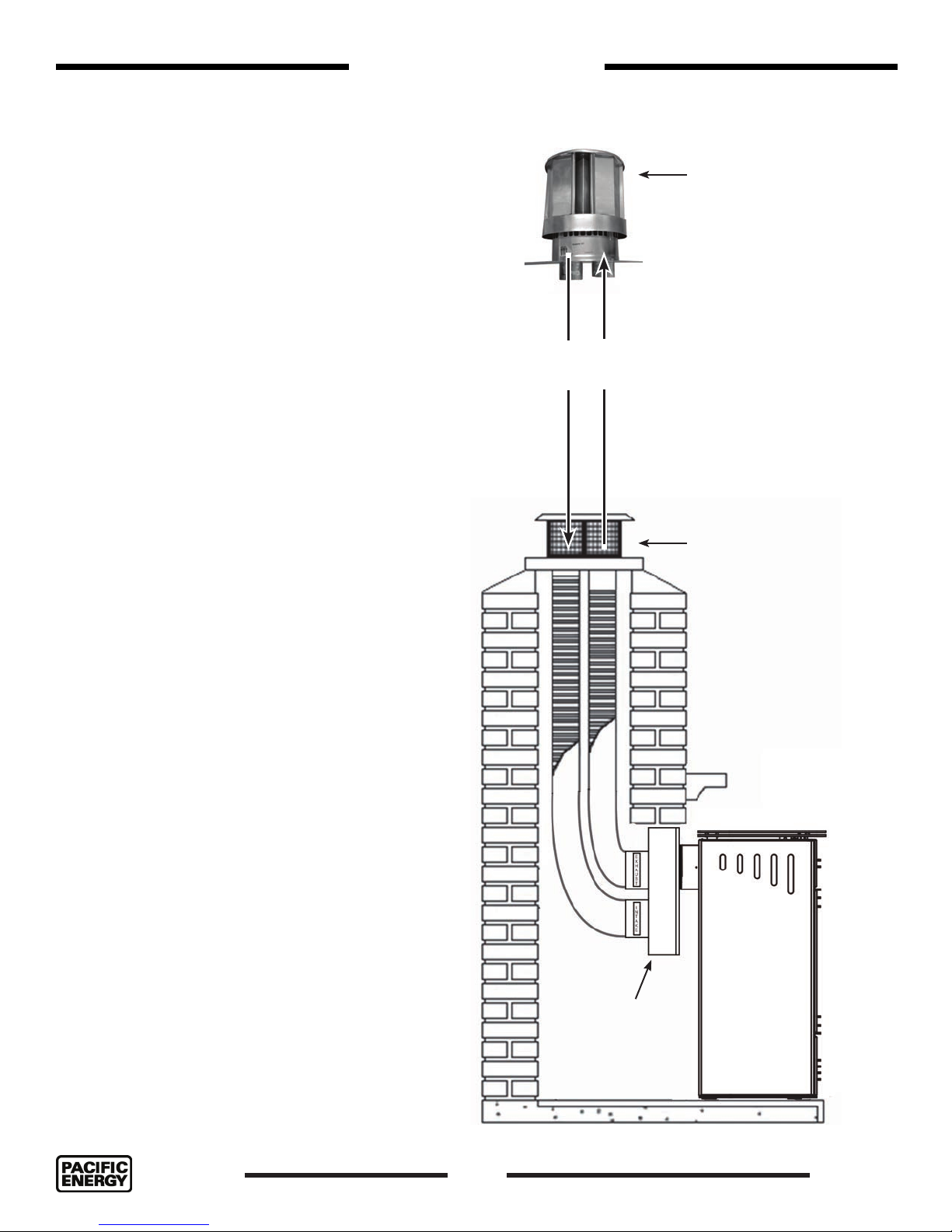
Co-Linear Venting
Simpson Duravent High-Wind (cap style) Co-Linear
Kit w/Flex (46DVA-CL34) or Simpson Duravent Prairie
(cap style) Co-Linear Kit w/Flex (46DVA-CL34P) are
recommended for use with this appliance.
Visit http://www.duravent.com for kit details.
High wind cap
Co-Linear Venting
Notes:
1. Measure chimney height, cut ex liner (min.10’
to termination) as required. Mark one pipe at
both ends to identify combustion air intake
pipe from ue outlet pipe.
2. Attach marked ex liner pipe to the intake side
of vent terminal. Seal and secure with sealant
and screws provided. Attach the other pipe
to the outlet side of vent terminal. Seal and
secure with sealant and screws provided.
3. Insert both ex liners from top of the chimney,
down through the damper opening.
4. Before attaching vent terminal to top of chimney, apply a bead of caulking to top of clay
liner. Slip vent terminal over liner and secure in
place with lateral retaining bolts.
5. For larger chimneys, ashing will need to be
constructed according to local building codes.
NOTE:
If venting the Mirage 30 through an existing
replace opening using a co-axial to co-linear adapter, the customer will have a couple
of aesthetic options which include:
Intake
Air
Exhaust
Air
• Mirage 30 requires a 3
inch diameter exhaust
vent and a 3 inch
intake vent.
• Max. Vent Height 50’
(15.25M) to termination
• Min. Vent Height 10’ (3m)
to termination.
Prairie cap
^ a vent shall not terminate directly above a side-walk or paved driveway which is located between two single family dwellings and serves both dwellings*
** only permitted if veranda, porch, deck, or balcony is fully open on a minimum of 2 sides beneath the oor*
* as speci ed in CGA B149 Installation Codes, Note: local Codes or Regulation may require different clearances
* for U.S.A. Installations follow the current National Fuel Gas Code, ANSI Z223.1
1. sealing up the existing replace opening
with a cover or other material, leaving
room in the cover or other material to
accomodate the adapter so that it is
positioned ush (Figure 5) with the cover
or other material.
2. Position the Mirage 30 so that it and the
adapter are located outside of the existing replace opening.
Figure 5: Mirage co-linear venting.
5055.MR30-A
Co-Axial to
Co-Linear
adapter
8
180516-36
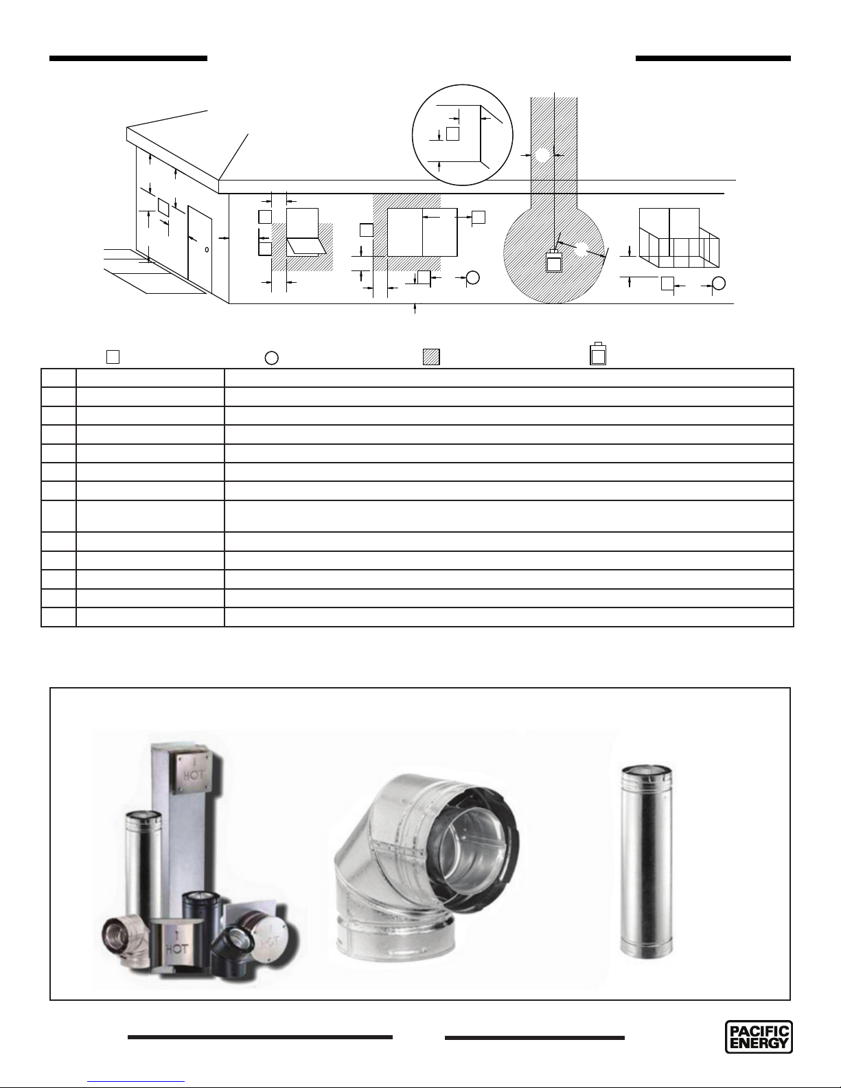
Vent Terminal Minimum Clearances
G
V
A
D
E
V
B
L
C
FIXED
V
CLOSED
F
OPEN ABLE
V
B
OPEN-
V
B
B
ABLE
A
FIXED
CLOSED
V
V
B
A
J
Figure 6: Minimum exterior clearances
VENT TERMINAL
V
A= *12 inches (30 cm) min. Clearances above grass, top of plants, wood, combustible veranda, porch, deck, or balcony.
B= *12 inches (30 cm) min. Clearance beside or below a window or door that may be opened.
C= 12 inches (30 cm) min. Clearance to permanently closed window recommended to prevent condensation on window.
D= 30 inches (76 cm) min. Vertical clearance to ventilated soft located above the terminal within a horizontal distance of 16 inches (40 cm) .
E= 30 inches (76 cm) min. Clearance to unventilated soft.
F= 8 inches (15 cm) min. Clearance to outside corner.
G= 8 inches (15 cm) min. Clearance to inside corner.
H= 3 feet (90 cm) min. *Not to be installed above a meter/regulator assembly within 3feet (90 cm) horizontally from the center-line of
I= *6 feet (1.8 m) min. Clearance to service regulator vent outlet.
J= *12 inches (30 cm) min. Clearance to non mechanical air supply inlet to building or the combustion air inlet to any other appliance.
K= *6 feet (1.8 m) min. Clearance to a mechanical air supply inlet.
L= 7 feet (2.1 m) min. ^ Clearance above paved side-walk or a paved driveway located on public property
M= 30 inches (76 cm) min. Clearance under veranda, porch, deck, or balcony
the regulator.
AIR SUPPLY INLET
A
AREA WHERE TERMINAL
IS NOT PERMITTED
H
I
G
M
GAS METER
G
V
A
K
This stove is certied for use with 4” x 6-5/8”co-axial venting, and co-linear venting components. It is permitted to
only use certied venting for this stove. See charts (Figure 8) & (Figure 9) for a list of approved co-axial venting components. For co-linear venting, use approved co-axial to co-linear adapter and 3” venting material - (See page 8).
180516-36
Figure 7: Co-axial venting components.
9
5055.MR30-A

NOTE: Mixing venng components from different manufacturers is inadvisable.
4” x 6 5/8” Rigid Piping Components Cross Reference
Venting Components
Figure 8: Venting Components 1.
4” x 6 5/8” Rigid Pipe Components Cross Reference Chart
Figure 9: Venting Components 2.
5055.MR30-A
10
180516-36
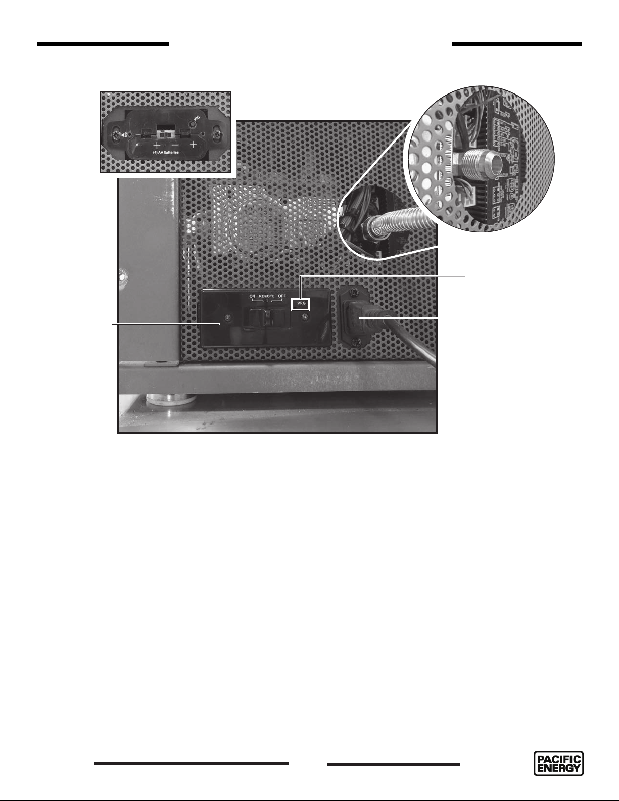
Battery holder
Gas and Electrical Connections
Gas connection
PRG reset
Battery holder
face plate and
manual “ON//
REMOTE/OFF”
switch
Gas connection
Connect the gas supply line to the 1/2” are tting at the rear of the unit as seen
in (Figure 10). Please see the gas supply section of the manual for requirements
of the gas supply.
Electrical connection
Plug the provided IEC power cord into the receptacle at the rear of the unit as
shown in (Figure 10). The battery holder and manual “ON/REMOTE/OFF” switch
is also located here. See details of operation on page 17.
Electrical connection
Figure 10: Gas and Electircal connection.
180516-36
11
5055.MR30-A
 Loading...