

Pacific energy MIRAGE 18 Installation And Operating Instructions Manual
I NSTALLER:
Retain th is m an ual f or f uture ref eren ce.
Leav e th is m an ual with th e applian ce.
CONSUMER:
WARNING: If the information in these
instructions is not followed exactly a fi re or
explosion may result causing property
damage, personal injury or death.
FOR YOUR SAFETY
Do not store or use gasoline or other
fl ammable vapours and liquids in the
vicinity of this or any other appliance.
WHAT TO DO IF YOU SMELL GAS
• Do not try to light any appliance.
• Do not touch any electrical switch.
• Do not use any phone in your building.
• Immediately call your gas supplier
from a neighbour’s phone. Follow the
gas supplier’s instructions.
• If you cannot reach your gas supplier
call the fi re department.
SERIAL #
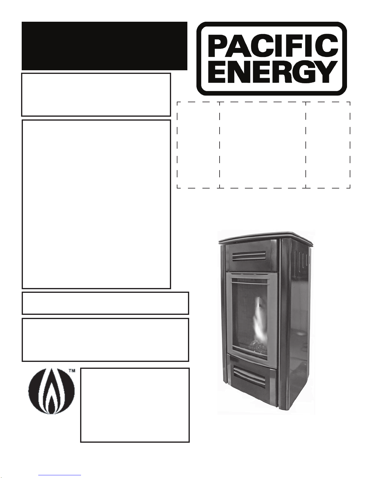
MIRAGE 18
INSTALLATION AND
OPERATING INSTRUCTIONS
Installation and service must be performed by a qualifi ed installer, service
agency or the gas supplier.
This appliance is suitable for installation in a
bedroom or bed sitting room.
This appliance is only for use with the type of
gas indicated on the rating plate. This
appliance is not convertible for use with
other gases unless a certifi ed kit is used.
This appliance is certifi ed for
use in Australia with Natural
Gas and Liquid Propane Gas.
Gas Safety
Cer fi ed
AS/NZS 5263.1.3
SAI-400322
This appliance is certifi ed
for use in New Zealand with
Natural Gas only.
MODEL: MI RAG E 1 8 , SERI ES: A
BALANCED FLUE FREE STANDING
GAS HEATER
060718-44
MR18 AU
100000432-50

Table of Contents
Caution ...................................................................................... 3
Safety ........................................................................................ 4
Warnings and Cautions ............................................................. 5
Operating Instructions ................................................................7
First Fire ..................................................................................... 8
Special Operator Note ............................................................... 8
Remote Control Operation ........................................................ 8
Remote Transmitter Description ...................................... 10
Transmitter (Remote Control with LCD Display) ............... 10
IFC Module....................................................................... 10
Initializing the Fireplace for the rst time ......................... 10
Temperature indication Display .........................................11
Turn on the Stove ..............................................................11
Turn off the Stove ..............................................................11
Manual Bypass of the Remote Control Transmitter ..........11
Remote Flame Control ......................................................11
Room Thermostat (Transmitter Operation) ...................... 12
Smart Thermostat (Transmitter Operation) ...................... 12
Comfort Fan Speed Control ............................................. 12
Continuous Pilot/Intermittent Pilot (CPI/IPI) selection ..... 13
Key Lock .......................................................................... 13
Low Battery Power Detection .......................................... 13
Receiver ........................................................................... 13
Lighting Instructions ................................................................ 14
Installing the Mirage 18 ........................................................... 15
Installation Checklist ........................................................ 15
Mirage 18 Dimensions ............................................................. 16
Locating the Stove ...................................................................17
Clearances to Combustibles ................................................... 18
Flue Terminal Minimum Clearances ........................................ 19
Co-axial Flueing ...................................................................... 20
Flue Components .....................................................................21
Gas and Electrical Connections ...............................................21
Gas Supply .............................................................................. 22
Gas Pressure Testing Procedure ............................................. 23
Firebox Panel Removal / Installation ....................................... 24
Removal ........................................................................... 24
Burner Kit/Media Installation/Removal .................................... 25
Installation ........................................................................ 25
Removal ........................................................................... 25
Optional Glass Media Installation ............................................ 26
Optional Log Media Installation ................................................27
Log Placement ..................................................................27
Door Removal / Installation ..................................................... 28
Battery Installation ................................................................... 29
Air Adjustment ......................................................................... 30
Pilot Adjustment .......................................................................31
Comfort Fan Removal / Installation ......................................... 32
Exterior Panel Removal/Installation ......................................... 33
Removal ........................................................................... 33
Installation ........................................................................ 34
Pilot Assembly Replacement ................................................... 35
To access and remove the pilot assembly. ...................... 35
Replacing the pilot assembly. ...........................................37
Propane Conversion ................................................................ 39
Maintenance ............................................................................ 40
Glass Door: ...................................................................... 40
Annual Inspection: ............................................................ 40
Periodically ....................................................................... 40
Replacement Parts ...................................................................41
Wiring Diagram ........................................................................ 42
Rating Label ............................................................................ 43
LISTINGS AND CODE APPROVALS
These gas appliances have been tested in accordance with AS/NZS 5263.0:2017 and
AS/NZS 5263.1.3 and have been certified by SAI GLOBAL Limited for installation and operation
as described in these Installation and Operating Instructions. Must be installed as per AS/NZS
5601.1. Your unit should be serviced annually by an authorized service person.
AS/NZS 5601.1:2013 contains the requirements and methods of compliance for the “design,
installation and commissioning of gas installations that are associated with the use or
intended use of fuel gases such as natural gas, LP gas or biogas.”
100000432-50
2
060718-44
DANGER
Caution
FOR YOUR SAFETY - Do not install or operate your Pacic Energy gas stove without rst reading
and understanding this manual. Any installation or operational deviation from the following
instructions voids the Pacic Energy ™ Warranty and may prove hazardous.
This appliance and its individual shut off valve must be disconnected from gas supply piping system
during any pressure testing of that system at test pressures in excess of 1/2 psig (3.5 kPa).
This appliance must be isolated from the gas supply piping system by closing its individual manual
shut off valve during any pressure testing of the gas supply piping system at test pressures equal to
or less than 1/2 psig (3.5 kPa).
Note: When lit for the rst time, the appliance will emit a slight odour for a couple of hours. This
is due to the curing of paints, sealants and lubricants used in the manufacturing process. This
condition is temporary. Open doors and windows to ventilate area. Smoke and fumes caused by the
curing process may cause discomfort to some individuals.
Do not use the gas stove if any part has been under water. Immediately call a qualied service
technician to inspect the gas stove and to replace any part of the control system and any gas control
which has been under water.
This stove is equipped with a micro mesh safety screen for your protection and
must be installed with the unit. Removal of the safety screen will cause the stove to
become a burn hazard.
!
HOT GLASS WILL CAUSE
BURNS.
A barrier designed to reduce the risk of burns from the
hot viewing glass is provided with the appliance and
shall be installed for the protection of children and
other at-risk individuals.
DO NOT TOUCH GLASS UNTIL
COOLED.
NEVER ALLOW CHILDREN TO
TOUCH GLASS.
060718-44
3
100000432-50

Safety
Due to high temperatures, this gas appliance should be located out of trafc and away from furniture
and draperies.
Children and adults should be alerted to the hazards of high surface temperatures and should stay
away to avoid burns or clothing ignition.
Young children should be carefully supervised when they are in the same room as the appliance.
Toddlers, young children, and others may be susceptible to accidental contact burns. A physical
barrier is recommended if there are at-risk individuals in the house. To restrict access to a replace
or stove, install an adjustable safety gate to keep toddlers, young children, and other at-risk
individuals out of the room and away from hot surfaces. Clothing or other ammable material should
not be placed on or near the appliance.
Any grill, panel or door removed for servicing the unit must be replaced prior to operating. Failure to
do so may create a hazardous condition.
Installation and repair should be done by a qualied service person. The appliance should be
inspected before use and at least annually by a professional service person. More frequent cleaning
may be required due to excessive lint from carpeting, bedding material, etc. It is imperative that
control compartments, burners and circulating air passageways of the appliance be kept clean.
It is our policy that no responsibility is assumed by the Company or by any of its employees or
representatives for any damages caused by an inoperable, inadequate, or unsafe condition which is
the result, either directly or indirectly, of any improper operation or installation procedures.
This appliance must not be connected to a chimney ue serving a separate solid fuel burning
appliance.
100000432-50
4
060718-44
Warnings and Cautions
• DO NOT SPRAY AEROSOLS IN THE VICINITY OF THIS APPLIANCE WHILE IT’S IN
OPERATION.
• DO NOT USE OR STORE FLAMMABLE MATERIALS IN OR NEAR THIS
APPLIANCE.
• DO NOT PLACE ARTICLES ON OR AGAINST THIS APPLIANCE.
• DO NOT MODIFY THIS APPLIANCE.
WARNING
SHOCK HAZARD. CAN CAUSE SEVERE INJURY OR DEATH. THIS DEVICE IS POWERED
BY LINE VOLTAGE. DO NOT TRY TO REPAIR THIS DEVICE. IN NO WAY IS THE
ENCLOSURE TO BE TAMPERED WITH OR OPENED. DISCONNECT FROM LINE VOLTAGE
BEFORE PERFORMING ANY MAINTENANCE.
DUE TO HIGH TEMPERATURES, THIS GAS APPLIANCE SHOULD BE LOCATED OUT OF
TRAFFIC AND AWAY FROM FURNITURE AND DRAPERIES.
CHILDREN AND ADULTS SHOULD BE ALERTED TO THE HAZARDS OF HIGH SURFACE
TEMPERATURES AND SHOULD STAY AWAY TO AVOID BURNS OR CLOTHING IGNITION.
YOUNG CHILDREN SHOULD BE CAREFULLY SUPERVISED WHEN THEY ARE IN THE
SAME ROOM AS THE APPLIANCE. TODDLERS, YOUNG CHILDREN AND OTHERS
MAY BE SUSCEPTIBLE TO ACCIDENTAL CONTACT BURNS. A PHYSICAL BARRIER IS
RECOMMENDED IF THERE ARE AT RISK INDIVIDUALS IN THE HOUSE. TO RESTRICT
ACCESS TO A FIREPLACE OR STOVE, INSTALL AN ADJUSTABLE SAFETY GATE TO
KEEP TODDLERS, YOUNG CHILDREN AND OTHER AT RISK INDIVIDUALS OUT OF THE
ROOM AND AWAY FROM HOT SURFACES.
CLOTHING OR OTHER FLAMMABLE MATERIAL SHOULD NOT BE PLACED ON OR NEAR
THE APPLIANCE.
THE GUARD IS FITTED TO THIS APPLIANCE TO REDUCE THE RISK OF FIRE OR
INJURY FROM BURNS AND NO PART OF IT SHOULD BE PERMANENTLY REMOVED.
FOR PROTECTION OF YOUNG CHILDREN OR THE INFIRM, A SECONDARY GUARD IS
REQUIRED.
DO NOT INSTALL IN A FIREPLACE.
060718-44
5
100000432-50
WARNING
FIRE HAZARD. CAN CAUSE SEVERE INJURY OR DEATH. THE RECEIVER CAUSES
IGNITION OF THE APPLIANCE. THE APPLIANCE CAN TURN ON SUDDENLY. KEEP
AWAY FROM THE APPLIANCE BURNER WHEN OPERATING THE REMOTE SYSTEM OR
ACTIVATING MANUAL BYPASS OF THE REMOTE SYSTEM.
INSTALLATION AND REPAIR SHOULD BE DONE BY A QUALIFIED SERVICE PERSON.
THE APPLIANCE SHOULD BE INSPECTED BEFORE USE AND AT LEAST ANNUALLY
BY A PROFESSIONAL SERVICE PERSON. MORE FREQUENT CLEANING MAY BE
REQUIRED DUE TO EXCESSIVE LINT FROM CARPETING, BEDDING MATERIAL, ETC. IT
IS IMPERATIVE THAT CONTROL COMPARTMENTS, BURNERS AND CIRCULATING AIR
PASSAGEWAYS OF THE APPLIANCE BE KEPT CLEAN.
THIS APPLIANCE MUST NOT BE CONNECTED TO A CHIMNEY FLUE SERVING A
SEPARATE SOLID FUEL BURNING APPLIANCE.
WARNING: FAILURE TO INSTALL THIS APPLIANCE CORRECTLY WILL VOID YOUR
WARRANTY AND MAY CAUSE A SERIOUS HOUSE FIRE.
Congratulations on your purchase of a Pacific Energy Gas Appliance.
Your appliance has been professionally installed by:
Dealer name: ___________________________________________________
Phone Number:___________________________________________________
If you discover any problems with your gas appliance contact your dealer immediately to have the
unit repaired.
Caution: Do not attempt to repair the replace because you may cause injury to yourself or others, and risk
causing damage to the unit.
Before operating your appliance carefully read this manual and pay close attention to all Safety
Warnings.
The manual contains important information on the unit’s safe operation and maintenance.
100000432-50
6
060718-44
Operating Instructions
Warning: The home owner must not make any adjustments to the appliance
other than what can be achieved by using the remote handset (Figure 1) and
the settings control / battery holder located at the bottom of the surround
backing plate (Figure 20). Any other adjustments must be performed by a
qualified service technician.
Before operating this appliance, proceed through the following checklist.
1. Read and understand these instructions before operating this appliance.
2. Check to see that all wiring is correct and enclosed to prevent possible shock.
3. Check to ensure that there are no gas leaks.
4. Make sure that the glass door is in place. Never operate the appliance with the glass door
removed.
5. Verify that all ueing and the termination cap is unobstructed.
6. Verify log placement.
7. When lighting the appliance, the inside of the glass may fog up. This will burn off after a few
minutes of operation.
NOTE: After 3 failed
attempts to ignite, the
fireplace will enter a
1 minute hibernation
NOTE: Fireplace may take
up to 30 seconds to ignite
each time the “ON” button
has been selected.
period before attempting
to ignite again.
060718-44
7
100000432-50
First Fire
When lit for the rst time, the gas stove will emit a slight odour for a couple of hours. This is due to
the curing of paints, sealants and lubricants used in the manufacturing process. This condition is
temporary. Open doors and windows to ventilate area. Odors caused by the curing process may
cause discomfort to some individuals.
It is normal for stoves fabricated of steel to give off some expansion and/or contraction noises
during the start up or cool down cycle. Similar noises are found with your furnace heat exchanger or
cook stove oven.
Special Operator Note
NOTE: Pilot may take
up to 30 seconds to
ignite each time the
“ON” button has been
selected.
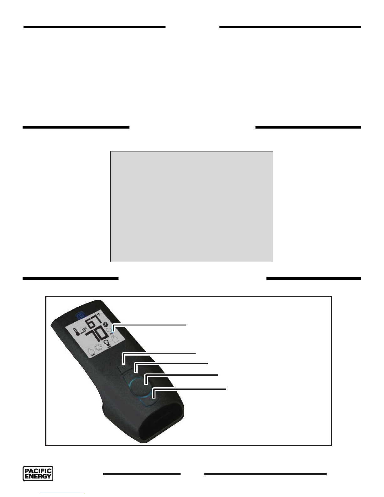
Remote Control Operation
Blue back lit LCD display
ON/OFF Key
THERMOSTAT Key
UP/DOWN Arrow Key
MODE Key
Figure 1: Pro ame 2 handset.
100000432-50
8
060718-44
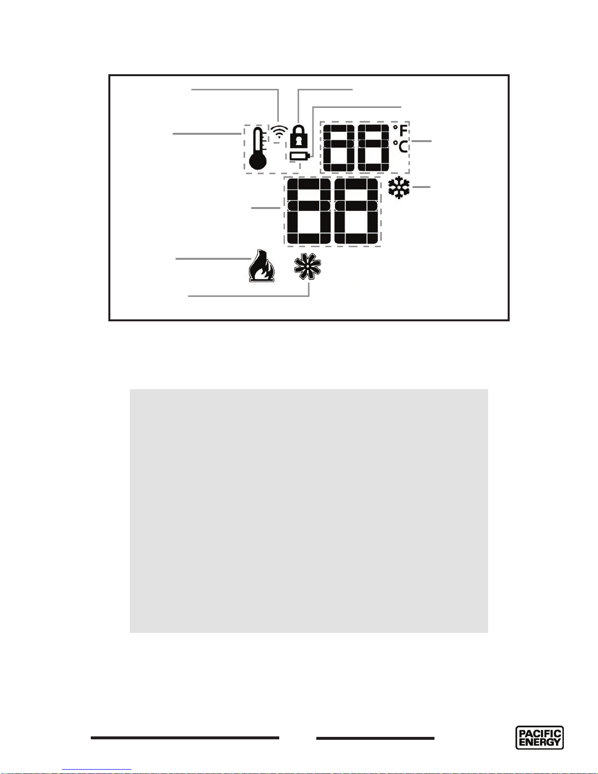
TRANSMISSION
THERMOSTAT OFF/
ON/SMART
OFF
ON
SMART
KEY LOCK
LOW BATTERY ALARM
ROOM
TEMPERATURE
SET POINT:
TEMPERATURE/LEVEL/STATE
FLAME ON
COMFORT FAN
Figure 2: Pro ame 2 LCD display.
Attention!
• Turn off the main gas supply for the appliance during
installation or maintenance of the receiver/module
device.
CPI MODE
MAX
• Turn off main gas supply for the appliance prior to
removing or reinserting the batteries.
• In case of remote control malfunction, turn off the
fi replace using the “on/off” main switch located on back
of stove.
• For installation/maintenance, turn off the fi replace at the
on/off switch located on the back of the unit and at the
fi replace power supply circuit breaker.
060718-44
9
100000432-50

Remote Transmitter Description
The Proame2 Remote Control consists of two elements:
1. Proame2 Remote Control Transmitter.
2. Proame Integrated Fireplace Control (IFC Module) board and a wiring harness to connect the IFC to the
gas valve and stepper motor (Figure 43).
Transmitter (Remote Control with LCD Display)
The Proame 2 Transmitter uses a streamline design with a simple key layout and an informative LCD display
(Figure 2). The remote control transmitter is powered by 3 AAA batteries. A mode key is provided to index
between the features and a thermostat key is used to turn on/off or index through thermostat functions
(Figure 1).
IFC Module
The Proame2 Integrated Fireplace Control (IFC) module is a device that allows automatic ignition and pilot
ame supervision and commands the functions of the replace. It’s congured to control the ON/OFF main
burner operation, giving the choice of both IPI (intermittent pilot ignition), and CPI (continuous pilot ignition)
modes. The Proame 2 IFC module controls and connects directly to the pilot assembly and the automatic
valve using low electric power.
The IFC module can be powered by both an AC power supply, and battery pack for back up. The Proame
2 offers the added ability to control the comfort fan speed from OFF through six (6) speeds. The external
batteries can provide DC power to the IFC allowing the batteries to be used only when line power is
interrupted or lost.
Operating Procedure
Initializing the Fireplace for the rst time
1. With the gas stove power plug unplugged and the main switch - located in the rear of the stove, turned to
the OFF position, remove the switches’ face plate and install 4 AA batteries into the battery holder (Figure
20). Once the batteries are installed and the switches’ face plate reattached, turn the selection switch to
“Remote” setting.
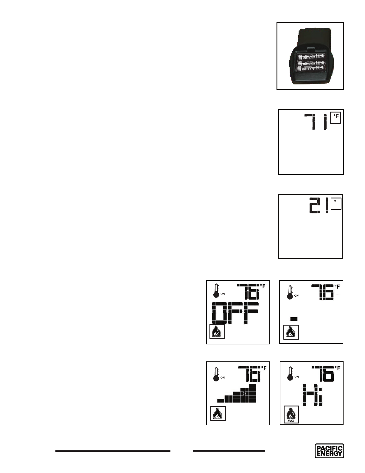
2. Install 3 AAA batteries into the Proame 2 Remote Control Transmitter (Figure 3).
3. Plug the power plug in and turn on the gas supply.
4. Insert a straightened paper clip into the opening marked “PRG” of the switches’ face plate Figure 20 and
press the program key once (alternately, if the face plate is already off, simply press the “PRG” button on
the battery holder). The IFC module, also located on the inside of the gas stove enclosure, will beep 3
times indicating that it is ready to synchronize with a remote control transmitter.
5. On the remote control transmitter, push the power on key once. The remote control transmitter will beep
4 times to indicate that the remote control transmitter and the IFC module are now synchronized. The
remote control transmitter is now ready to use.
100000432-50
10
060718-44
Using the Remote Control Transmitter
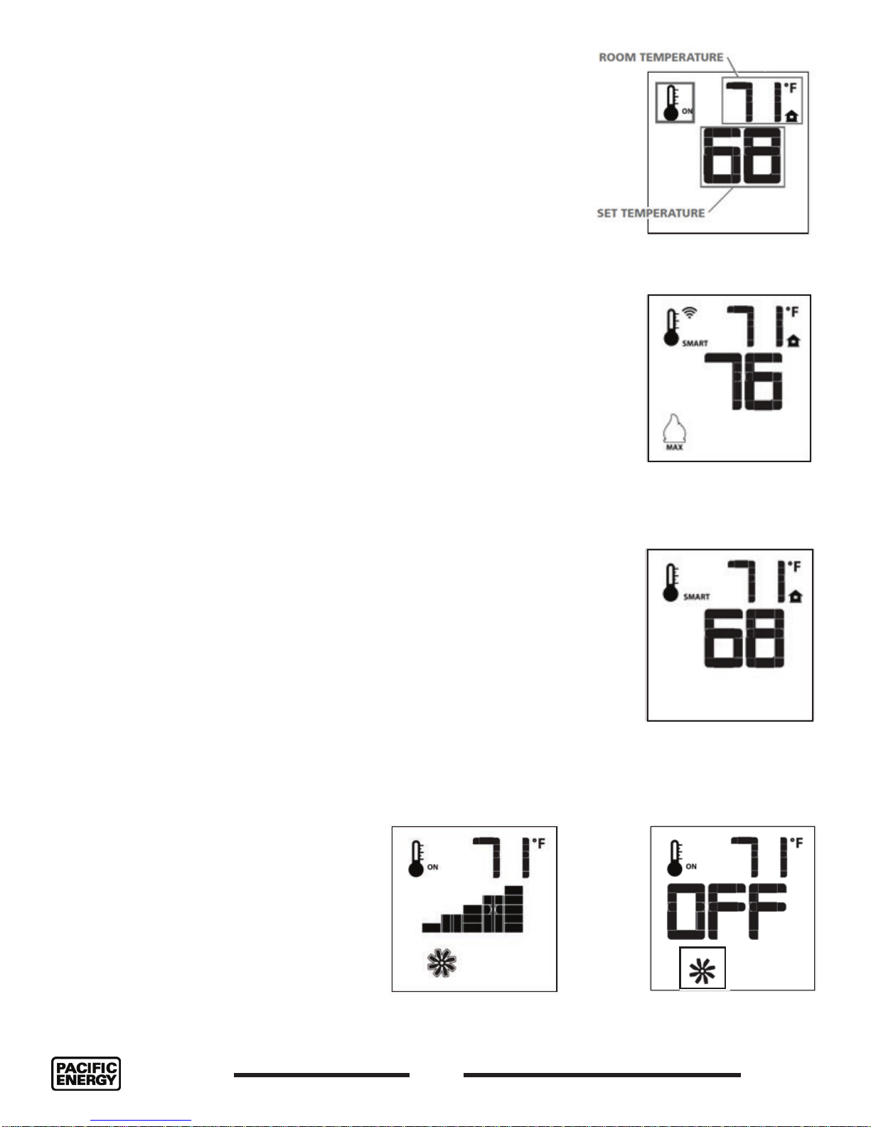
Temperature indication Display
With the remote control transmitter in the “OFF” position, press the thermostat
and mode keys at the same time. Look at the LCD screen on the remote control
transmitter to verify that a C or F is visible to the right of the room temperature
display (Figure 4 and Figure 5).
Turn on the Stove
With the stove OFF, press the ON/OFF key on the remote control transmitter.
The remote control transmitter display will show the active icons on the screen.
At the same time the wall switch will activate the stove via the IFC module. A
single “beep” from the IFC module will con rm reception of the command.
Turn off the Stove
With the stove ON, press the ON/OFF key on the remote control transmitter.
The remote control transmitter LCD display will only show the room temperature
(Figure 4 and Figure 5). At the same time the IFC module will turn off the stove.
A single “beep” from the IFC module con rms reception of the command.
Manual Bypass of the Remote Control Transmitter
If the batteries of the remote control transmitter are low or depleted, the gas
stove can be turned off manually using ON/OFF switch located on rear of the
gas stove (Figure 20). This will bypass the remote control transmitter.
Figure 3: Pro ame 2
remote control battery bay.
Figure 4: Display in
Fahrenheit.
C
Remote Flame Control
The Pro ame 2 has six (6) ame levels (Figure 6).
With the gas stove turned on, and the ame level at
maximum height, press the down arrow key once to
reduce the ame height by one step until the ame is
turned off.
The up arrow key will increase the ame height each
time it is pressed. If the up arrow key is pressed while
the gas stove is on but the ame is off, the ame will
come on in the high position. A single “beep” will
con rm reception of the command.
Figure 6: Flame level control.
Figure 5: Display in
Celsius.
Flame level OFF Flame level 1
Flame level 5
Flame level MAX
060718-44
11
100000432-50
Room Thermostat (Transmitter Operation)
The remote control transmitter can operate as a room thermostat.
The thermostat can be set to a desired temperature to control the
comfort level in a room. To activate this function, press the thermostat
button (Figure 1), the LCD display on the remote control transmitter
will change to show that the room thermostat is “ON” and the set
temperature is now displayed (Figure 7). To adjust the set point, press
the up or down arrow button until the desired set point temperature is
displayed on the LCD screen of the remote control transmitter.
Smart Thermostat (Transmitter Operation)
The Smart Thermostat function adjusts the ame height in accordance
to the difference between the set point and the room temperatures.
As the room temperature gets closer to the set point, the Smart
Function will modulate the ame down. If the room temperature is
cool, the Smart Function will modulate the ame up. To activate this
function, press the THERMOSTAT button (Figure 1) until the word
“SMART” appears to the right of the temperature icon Figure 8. To
adjust the set point, press the up or down arrow buttons on the
handset until the desired set point temperature is displayed on the
LCD screen of the remote control transmitter (Figure 9).
Figure 7: Room
temperature.
Figure 8: Smart ame
function MAX temp.
Comfort Fan Speed Control
If the Stove is equipped with a hot air circulating fan, the speed of
the fan can be controlled by the Pro ame 2 System. The fan speed
can be adjusted through six (6) speeds (Figure 10). To activate this
function use the Mode Key (Figure 1) to index to the fan control
icon (Figure 11). Use the Up/Down Arrow Keys (Figure 1) to turn on,
off or adjust the fan speed (Figure 23). A single “beep” will con rm
reception of the command.
Figure 10: Comfort fan
max.
Figure 9: Smart ame
adjusting temperature.
Figure 11: Comfort fan
off.
100000432-50
12
060718-44
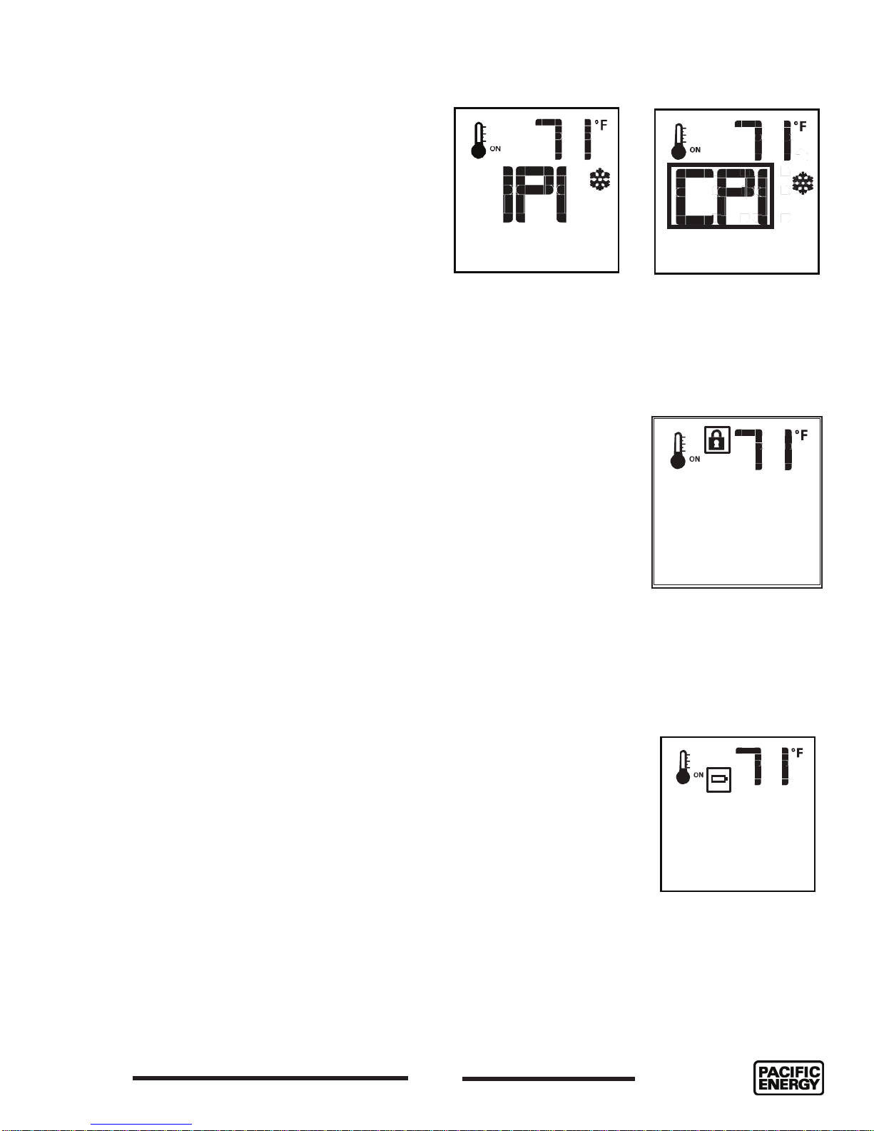
Continuous Pilot/Intermittent Pilot (CPI/IPI)
selection
With the system in the “OFF” position, press the
Mode Key (Figure 1) to index to the CPI mode
icon (Figure 12). Pressing the Up Arrow Key will
activate the Continuous Pilot Ignition mode (CPI).
Pressing the Down Arrow Key will return to IPI.
A single “beep” will con rm the reception of the
command.
Figure 12: IPI - CPI control.
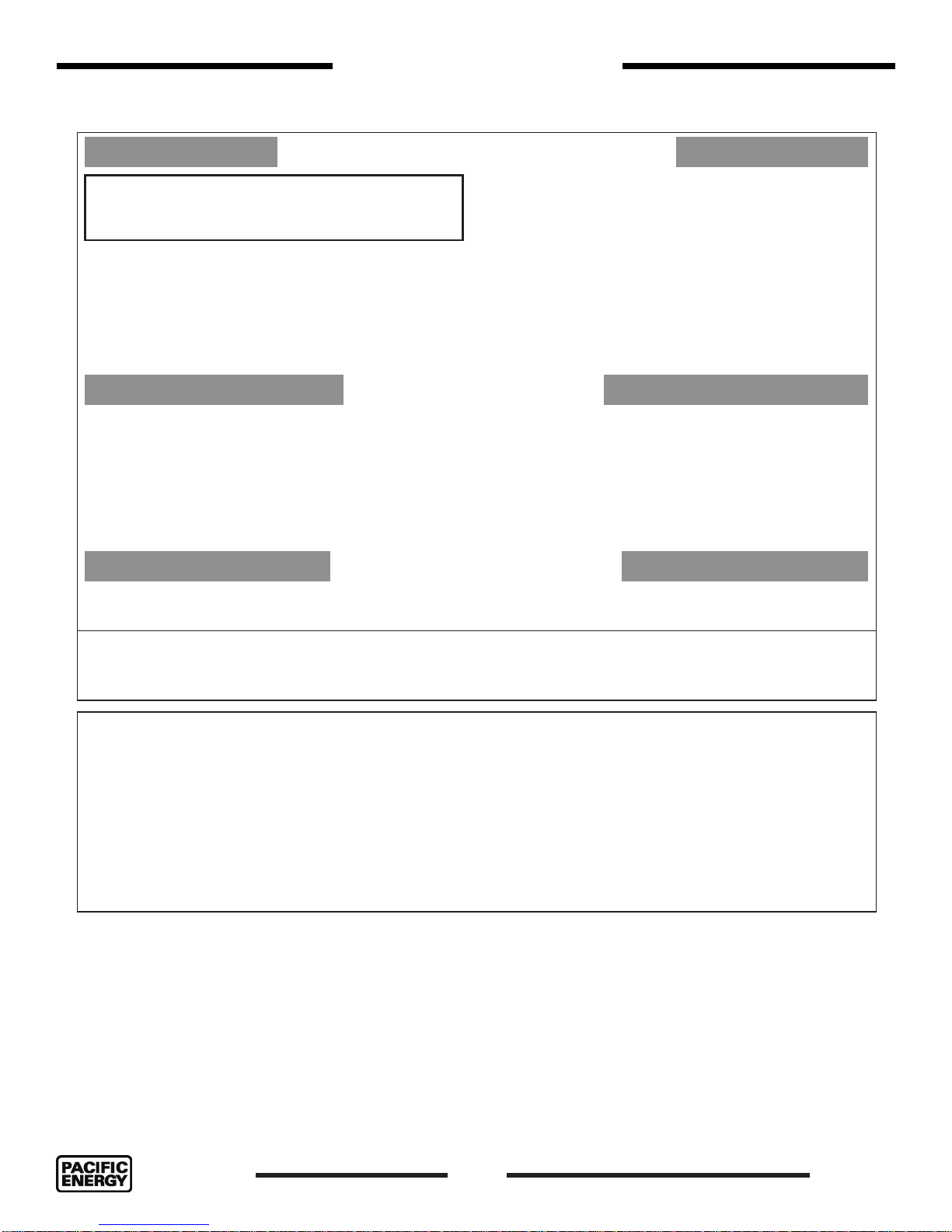
Key Lock
This function will lock the keys to avoid unsupervised operation. To activate this
function, press the MODE and UP keys at the same time (Figure 1).The lock icon
will appear (Figure 13). To deactivate this function, press the MODE and UP key at
the same time.
Low Battery Power Detection
Transmitter
The life span of the remote control batteries depends on various factors: quality of
the batteries used, the number of ignitions of the Stove, the number of changes to
the room thermostat set point, etc.
Figure 13: Key lock.
When the remote control transmitters’ batteries are low, an icon will appear on the
LCD display (Figure 14) of the remote before all battery power is lost. When the
batteries are replaced this icon will disappear.
Receiver
The life span of the IFC module batteries depend on various factors: quality of
the batteries used, the number of ignitions of the Stove, the number of changes
to the room thermostat set point, etc.
When the IFC batteries are low, a “double-beep” will be emitted from the IFC
module when it receives a command from the remote. This is an alert for a low
battery condition for the IFC module. When the batteries are replaced, a single
“beep” will be emitted from the IFC module when a key is pressed - “Initializing
the Fireplace for the rst time” on page 10.
Figure 14: Low battery.
060718-44
13
100000432-50
FOR YOUR SAFETY READ BEFORE LIGHTING
WARNING:
A. T his appliance is equip ped with an ignition device which
building.
- Immediately call your gas supplier from a neig hbour 's p hone. Follow
1. STOP! Read the safety information above on this label.
"On/ Off" switch for the fireplace to OFF, turn off all electric power
to the fireplace and call your service technic ian or gas sup pl ier.
6. Set fireplace to desired setting by using hand held remote.
1.
2. Turn off all electric power to the appliance and remove backup
Due to high surface temperatures, keep children, clothing and furniture away. Keep burner and control compartment clean. See installation and
CAUTION:
5051.185
Lighting Instructions
fire or explosion may result causing property damage,
personal injury or loss of life.
If you do not follow these instructions exactly, a
automatically lights the pilot. Do not try to light the pilot by hand.
B. BEFORE LIGHTING smell all around the appliance area for gas. Be
sure to smell next to the floor because some gas is heavier than
air and will settle on the floor.
WHAT TO DO IF YOU SMELL GAS:
- Do not try to light any appliance.
- Do not touch any electric switch; do not use any phone in your
LIGHTING INSTRUCTIONS
2. This appliance is equipped with an ignition device which
automatically lights the pilot. Do not try to light the pilot by hand.
3. Push the "On/ Off" switch to turn the fireplace ON.
- If the burner does light go to step 6.
- If the burner does not light, complete steps 4 through 5.
- If the burner will not light or stay lit after several tries, push the
TO TURN OFF GAS APPLIANCE
Push the "on/ off" switch to the "Off" position.
the gas supplier's instructions.
- If you cannot reach your gas supplier, call the fire department.
C. Use only your hand to push in or turn the gas control knob. Never use
tools. If the knob will not push in or turn by hand, don't try to repair it,
call a qualified service technician. Force or attempted repair may
result in a fire or explosion.
D. Do not use this appliance if any part has been under water.
Immediately call a qualified service technician to inspect the
appliance & to replace any part of the control s
control which has been under water.
ystem & any gas
Note: Sufficient time must be allowed for air to escape from lines if
the unit is being lit for the first time.
4. Push the "On/ Off" switch to the fireplace Off.
5. Allow sufficient length of time (minimum 5 minutes) for any gas in the
combustion chamber to escape. If you still smell gas, STOP! Follow
"B" in the safety information above on this label. If you don't smell
gas, go to step 3.
batteries if service is to be performed or for extended shutdown.
operating instructions accompanying the appliance.
A cause de la temperature elevee des parios, tenir eloignes les enfants, les vetements et les meubles. Maintenir propres le bruleur et le
compartiment de commande. Voir les instructions relatives a l'installation et au fonctionnement qui accompagnent l'appareil.
Hot while in operation. Do not touch. Severe burns may result. Keep children,
clothing, furniture, gasoline and other liquids having flammable vapours away. Keep burner and control
compartment clean. See installation and operating instructions accompanying the appliance.
ATTENTION:L'appareil est chaud lorsqu'il fonctionne. Ne pas toucher l'appareil. Risque de
brûlures graves. Serveiller les enfants. Garder les vêtements, le meubles, l'essence ou autres liquides
produisant des vapeurs infl ammables loin de l'appareil. S'assurer que le brûleur et le compartiment des
commandes sont propres. Voir les instructions d'installation et d'utilisation qui accompagnent l'appareil.
050615
Figure 15: Mirage 18 Lighting Instructions.
MR18/G958
100000432-50
14
060718-44
 Loading...