

Pacific energy granville Installation And Operating Instructions Manual
IMPORTANT:
THESE INSTRUCTIONS ARE TO
REMAIN WITH THE HOMEOWNER
WARNING: If the information in this
manual is not followed exactly, a fire or
explosion may result causing property
damage, personal injury or loss of life.
-- Do not store or use gasoline or other
flammable vapors and liquids in the vicinity
of this or any other appliance.
• WHAT TO DO IF YOU SMELL GAS
- Do not try to light any appliance.
f i r e - p a r t s . c o m
- Do not touch any electrical switch; do
not use any phone in your building.
- Immediately call your gas supplier
from a neighbour’s phone. Follow the
gas supplier’s instructions.
- If you cannot reach your gas supplier,
call the fire department.
• Installation and service must be performed
by a qualified installer, service agency or
the gas supplier.
Granville
Direct Vent Insert
SERIES A
INSTALLATION
AND OPERATING
INSTRUCTIONS
040805-24 GRNA # 5055.651
Contents
Caution .......................................................................................3
Safety .........................................................................................3
Maintenance ............................................................................... 3
Installation ................................................................................. 4
Clearances .................................................................................. 5
Venting .......................................................................................6
Rocker Switch ............................................................................7
Gas Supply .................................................................................8
Burner Removal ......................................................................... 9
Levelling Legs ...........................................................................9
Log Set .....................................................................................10
Surround Assembly ..................................................................12
Glowing Embers ......................................................................13
Louver Installation ................................................................... 13
f i r e - p a r t s . c o m
Glass Frame Installation ..........................................................13
Lighting Instructions................................................................14
First Fire ................................................................................... 15
Operation .................................................................................15
Primary Air Adjustment ...........................................................15
Optional Blower.......................................................................16
Optional Radiant Overlay ........................................................17
Replacement Parts....................................................................18
Burner Replacement Parts .......................................................20
Appendix A ..............................................................................21
Direct Vent Terminal Kit .................................................... 21
Vent Terminal Flashing Installation Guide ........................ 22
Safety Label ....................................................................... 23
IMPORTANT: When lit for the first time, the appliance will emit a slight odor for a couple of hours. This
is due to the curing of paints, sealants and lubricants
used in the manufacturing process. This condition is
temporary. Open doors and windows to ventilate
area. If optional fan kit has been installed, place fan
in the "OFF" position. Smoke and fumes caused by
the curing process may cause discomfort to some
individuals.
It is normal for fireplaces fabricated of steel to give
off some expansion and/or contraction noises during
the start up or cool down cycle. Similar noises are
found with your furnace heat exchanger or cook
stove oven.
040805-24 GRNA # 5055.651
2
Caution
Maintenance
FOR YOUR SAFETY - Do not install or operate your Pacific
Energy Granville Direct Vent Gas Insert without first reading
and understanding this manual. Any installation or operational deviation from the following instructions voids the
Pacific Energy Warranty and may prove hazardous.
This appliance and its individual shutoff valve must be disconnected from gas supply piping system during any pressure
testing of that system at test pressures in excess of 1/2 psig.
(3.5 kPa)
This appliance must be isolated from the gas supply piping
system by closing its individual manual shutoff valve during
any pressure testing of the gas supply piping system at test
pressures equal to or less than 1/2 psig. (3.5 kPa)
Note: When lit for the first time, the appliance will emit a
slight odour for a couple of hours. This is due to the curing of
paints, sealants and lubricants used in the manufacturing
process. This condition is temporary. Open doors and
windows to ventilate area. Smoke and fumes caused by the
curing process may cause discomfort to some individuals.
f i r e - p a r t s . c o m
Safety
Due to high temperatures, this gas appliance should be
located out of traffic and away from furniture and
draperies.
Children and adults should be alerted to the hazards of
high surface temperature and should stay away to avoid
burns or clothing ignition.
Young children should be carefully supervised when they
are in the same room as the appliance.
Clothing or other flammable material should not be placed
on or near the appliance.
Any grill, panel or door removed for servicing the unit
must be replaced prior to operating. Failure to do so may
create a hazardous condition.
Installation and repair should be done by a qualified
service person. The appliance should be inspected before
use and at least annually by a professional service person.
More frequent cleaning may be required due to excessive
lint from carpeting, bedding material, etc. It is imperative
that control compartments, burners and circulating air
passageways of the appliance be kept clean.
Caution: Turn off gas and electrical power supply and allow
ample time for unit to cool before servicing appliance. It is
recommended that this appliance and venting should be
inspected at least once a year by a qualified service person.
Do not use this heater if any part has been under water.
Immediately call a qualified service technician to inspect the
heater and to replace any part of the control system and any gas
control which has been under water.
Annual Inspection:
a) Clean louvers and air passage ways of excessive lint
buildup from carpeting, bedding material, etc. The flow of
ventilation air must not be obstructed.
b) Inspect logs and burner assembly for lint and soot buildup.
If excessive buildup of soot is present, have a qualified service
person inspect and adjust unit for proper combustion. Clean
logs and burner with a vacuum cleaner, paying close attention
to burner ports.
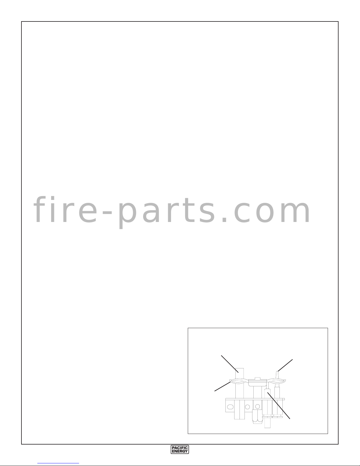
c) Check the pilot system for proper flame size and operation. Clean pilot free of lint or soot. (See Fig. #1)
d) Check that the vent pipe and vent terminal are open and
free from blockage or debris. If the venting system is disassembled for cleaning, it must be properly assembled and resealed.
e) Check glass panel gasket, replace if necessary. It is
important that the glass seal be maintained in good condition.
Note: The appliance area must be kept clear and free from
combustible materials, gasoline and other flammable vapours
and liquids.
Periodically:
a) Viewing glass may be cleaned with fireplace glass cleaner.
b) Exterior porcelain enamel finish may be cleaned with
soap and water.
Note: Never use abrasive cleaner to clean this appliance.
Do not clean glass when hot.
Fig. # 1
THERMOPILE
THERMOCOUPLE
It is Pacific Energy’s policy that no responsibility is
assumed by the Company or by any of its employees or
representatives for any damages caused by an inoperable,
inadequate, or unsafe condition which is the result, either
directly or indirectly, of any improper operation or
installation procedures.
040805-24 GRNA # 5055.651
PILOT
FLAME
ELECTRODE
3
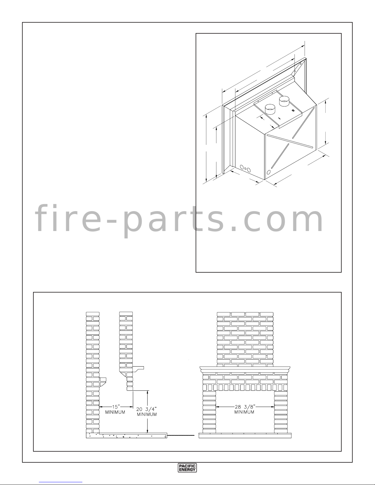
Installation
The Granville Direct Vent Gas Insert installation and
venting must conform to the current CAN/CGA-B149.1
installation code (in Canada) or the National Fuel Gas
Code, ANSI Z223.1 -1988 (in the USA), and approved per
local codes. Only qualified (licensed or trained) personnel
should install this product.
Fig. # 3
A
28 3/8"
Existing Fireplace
5"
(Masonry or Factory Built)
The Granville Direct Vent Gas Insert is designed to be
installed into a masonry or a factory built zero clearance
fireplace. The masonry fireplace must be built according to
the requirements of the Standards for Chimneys, Fireplaces,
Vents and Solid Fuel Burning Appliances, NFPA 211 (Latest
Edition) or applicable National, Provincial, State or local
codes. The factory built zero clearance fireplace and its
chimney must be certified and meet applicable National,
Provincial, State or local codes.
In order to sufficiently accommodate the Granville Direct
Vent Gas Insert, the minimum size of the fireplace should be
f i r e - p a r t s . c o m
28-3/8 inches wide, 20-3/4 inches high and 15 inches deep
(see Fig. #2).
The fireplace and its chimney should be swept and inspected.
The existing fireplace damper (if present) should be locked
open or removed completely if the opening is too small for two
- 3" flue liners to pass through.
B
20 3/4"
15"
Standard-size Surround
Plain and Embossed
Bevelled Panels .............. 38 1/2" wide x 27 1/4" high
Over-size Surround
Plain Flat Panels ............. 44 3/4" wide x 30 1/2" high
24 1/2"
AB
17 7/8"
Fig. # 2
040805-24 GRNA # 5055.651
4
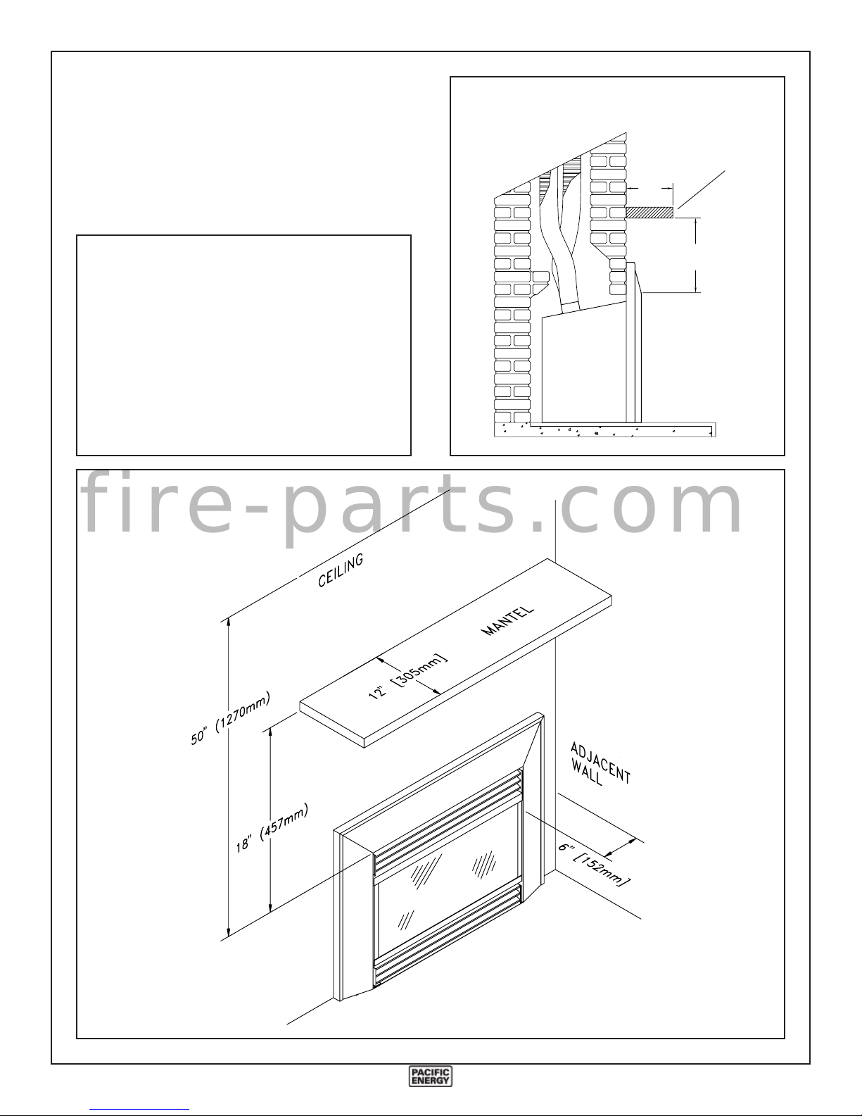
Clearances
The minimum clearances from the appliance to combustible
surfaces are shown on Fig. #4 and #5. Adequate clearances
around air openings and air supplies are required.
Fig. # 5
12"
(305mm)
Mantel
MINIMUM CLEARANCES
18"
(457mm)
TO COMBUSTIBLES:
Adjacent sidewall: ....................... 6.0 in. (152 mm)
Ceiling to appliance: .................... 50 in. (1270 mm)
Mantel to appliance: .................... 18 in. (457 mm)
Maximum mantel extension: ....... 12 in. (305 mm)
Mantel top support
to appliance ................................... 18 in. (457 mm)
Mantel side support
to appliance ..................................... 6 in. (150 mm)
Fig. # 4
Gas Insert
f i r e - p a r t s . c o m
040805-24 GRNA # 5055.651
5
Venting
Fig # 7
Vent Terminal
Caution: Only Flex Liner kit (MIND.FL25) or an approved
gas vent flue liner and a Vent Terminal (MIND.VTTERM)
is approved for use with this appliance.
Also approved for use is Simpson Dura-Vent GS
termination kits, both Standard Vertical Termination cap
(#980) and the Extended Vertical Termination cap (#930)
in conjunction with the 3" Co-Linear Termination kit
(#923GK).
No other venting system or components may be used.
1) Measure chimney height and cut flex liner as required.
Mark one of the pipes to identify combustion air intake
pipe from flue outlet pipe.
2) Attach marked flex liner pipe to the intake side (longer
collar) of vent terminal. Seal and secure with sealant and
screws provided. Attach the other pipe to the outlet side of
vent terminal. Seal and secure with sealant and screws
provided.
3) Insert both flex liners from top of the chimney, down
through the damper opening.
4) The vent terminal is sized to fit most typical chimneys.
Before attaching vent terminal to top of chimney, apply a
bead of caulking to top of clay liner. Slip vent terminal
over liner and secure in place with lateral retaining bolts.
f i r e - p a r t s . c o m
5) For larger chimneys, an optional flashing is available
which may be cut and fitted to suit. The flashing attaches
to the underside of the terminal with four nuts provided.
Caulk the flashing in place to seal any gaps.
Gas Insert
Seal
Min. ........ 8' (2.4m)
Max. ....... 36' (10.9m)
3" Flex
Liner
The vent terminal must be sealed in place to prevent water
from entering the existing chimney.
Fig # 6
Note: The vent must be a minimum 8' long and
must not exceed a total length of 36'.
6) Remove the screw located above the top louver which
retains the vent connector plate on the appliance. Attach
ends of the flex liners to the collars on top of the connector
plate.
Fig # 8
040805-24 GRNA # 5055.651
6
Make sure the marked inlet pipe is attached to the inlet side
Fig # 9
(marked "I"), and the unmarked pipe is attached to the
outlet side (marked "E") of the connector plate.
7) Seal and secure inlet pipe with sealant and screws provided.
8) Slip the 3 1/2" pipe clamp loosely over the end of the flex
flue pipe. Slide the pipe over the collar (marked "E") of the
vent connector plate and clamp tightly in place. Secure in
place with screws provided. No additional seal is required.
9) Position vent connector plate over top of unit as the Insert
is pushed into the fireplace. Clip connector plate at the
back of the unit, tip down into position and attach in place
with screws previously removed. Leave the Insert extending a couple of inches out of the fireplace temporarily to
allow for proper surround placement.
Rocker Switch
No electrical connection is required for the gas system
operation. The self generating pilot provides current for the
optional remote wall switch.
The installation of a wall switch allows for manual remote
operation of fireplace, and automatic operation with a wall
thermostat. Use a switch or thermostat rated for millivolts.
f i r e - p a r t s . c o m
Position the wall switch or thermostat so that a maximum of
25 feet of wiring from the switch to the fireplace is used. Use
18/2 thermostat wire. Connect the wall switch to the valve as
shown in Fig. #10.
Fig # 10
Thermostat
302010
Wall
Switch
Optional Wall Switch or Thermostat
Rocker Switch
Rocker Switch
(located top right corner of surround trim)
EA
F
O
F
P
I
L
T
O
N
O
Inlet
Pressure
Test Point
Manifold
Pressure
Test Point
THTP TH
TP
P
I
T
L
O
TP TPTH TH
L
O
H
I
P
I
T
L
O
Gas Valve
040805-24 GRNA # 5055.651
7
Gas Supply
Caution: The gas line should be installed by a qualified
service person in accordance with all building codes.
Consult local and/or national building codes before proceeding.
The gas valve inlet accepts a 3/8" N.P.T. fitting. Correct gas
line diameter must be used to assure proper operation.
The gas control is equipped with a capture screw type pressure
test port, therefore it is not necessary to provide an 1/8 inch
N.P.T. plugged tapping pressure port for checking gas pressure immediately upstream of the gas supply connection to the
appliance.
A knockout is provided at the bottom right rear of the appliance as an alternate entrance for a gas supply line (Fig. #11).
To use this entrance, remove the knockout from the rear of the
appliance. Remove the plastic bushing installed in the side and
reinstall into the hole at the rear of the appliance.
An optional 24" long flexible connector (part #
GASC.GASCON) may be used for easy gas connection. This
connector may exit the appliance through either the right front
or right rear access holes.
Correct gas pressure requirement:
Natural Gas Propane
Min. Pressure 5.0" wc 12.5" wc
(For purpose of input adjustment)
Max. Pressure 10.5" wc 13.0" wc
Manifold Pressure 3.8" wc 11.0" wc
f i r e - p a r t s . c o m
Fig # 11
Optional Blower
Cord Exit
Wire Harness
Rear Knockout
Gas Inlet
Exit
040805-24 GRNA # 5055.651
8
 Loading...