

Pacific energy G963 Installation And Operating Instructions Manual
INSTALER:
Leave this manual with the appliance.
CONSUMER:
Retain this manual for future reference.
WARNING: If the information in these
instructions is not followed exactly a fire or
explosion may result causing property
damage, personal injury or death.
FOR YOUR SAFETY
Do not store or use gasoline or other
flammable vapours and liquids in the vicinity
of this or any other appliance.
WHAT TO DO IF YOU SMELL GAS
Do not try to light any appliance.
Do not touch any electrical switch.
Do not use any phone in your building.
Immediately call your gas supplier
from a neighbour’s phone. Follow the
gas supplier’s instructions.
If you cannot reach your gas supplier
call the fire department.
Installation and service must be performed
by a qualified installer, service agency or the
gas supplier.
This appliance may be installed in an
aftermarket permanently located,
manufacture home (USA only) or mobile
home, where not prohibited by local codes.
This appliance is only for use with the type of
gas indicated on the rating plate. This
appliance is not convertible for use with
other gases unless a certified kit is used.
This appliance is suitable for installation in a
bedroom or bed sitting room.
G963
INSTALLATION AND
OPERATING INSTRUCTIONS
MODEL: G963
SERIES: A
DIRECT VENT GAS FIREPLACE
HEATER
040714 PZPE.G963BODYA 5055.963-A

Important Note for the Commonwealth of Massachusetts:
From Massachusetts Rules and Regulations 248 CMR 5.08:
(a) For all side wall horizontally vented gas fuelled equipment installed in every dwelling, building or structure used in whole or in part for residential purposes,
including those owned or operated by the Commonwealth and where the side wall exhaust vent termination is less than seven (7) feet above finished grade in the
area of the venting, including but not limited to decks and porches, the following requirements shall be satisfied.
1. INSTALLATION OF CARBON MONOXIDE DETECTORS. At the time of installation of the side wall horizontal vented gas fuelled equipment, the
installing plumber or gas fitter shall observe that a hard wired carbon monoxide detector with an alarm and battery back-up is installed on the floor level where the
gas equipment is to be installed, in addition, the installing plumber or gas fitter shall observe that a battery operated or hard-wired carbon monoxide detector with
an alarm is installed on each additional level of the dwelling, building or structure served by the side wall horizontal vented gas fuelled equipment. It shall be the
responsibility of the property owner to secure the services of qualified licensed professionals for the installation of hard-wired carbon monoxide detectors.
a. In the event that the side wall horizontally vented gas fuelled equipment is installed in a crawl space or an attic, the hard-wired carbon monoxide detector
with alarm and battery back-up may be installed on the next adjacent floor level.
b. In the event that the requirements of this subdivision cannot be met at the time of completion of installation, the owner shall have a period of thirty (30) days
to comply with the above requirements; provided, however, that during said thirty (30) day period, a battery operated carbon monoxide detector with an alarm shall
be installed.
2. APPROVED CARBON MONOXIDE DETECTORS. Each carbon monoxide detector as required in accordance with the above provisions shall comply
with NFPA 720 and be ANSI/UL 2034 listed as IAS certified.
3. SIGNAGE. A metal or plastic identification plate shall be permanently mounted to the exterior of the building at a minimum height of eight (8) feet above
grade directly in line with the exhaust vent terminal for the horizontally vented gas fuelled heating appliance or equipment. The sign shall read, in print size no less
than one-half (1/2) inch in size, “GAS VENT DIRECTLY BELOW. KEEP CLEAR OF ALL OBSTRUCTIONS”.
4. INSPECTION. The state or local gas inspector of the side wall horizontally vented gas fuelled equipment shall not approve the installation unless, upon
inspection, the inspector observes carbon monoxide detectors and signage installed in accordance with the provisions of 248 CMR 5.089(2)(a) 1 through 4.
(b) EXEMPTIONS. The following equipment is exempt from 248 CMR 5.089(2)(a) 1 through 4.
1. The equipment listed in Chapter 10 entitled “Equipment Not Required To Be Vented” in the most current edition of NFPA 54 as adopted by the Board; and
2. Product Approved side wall horizontal vented gas fuelled equipment installed in a room or structure separate from the dwelling, building or structure used in
whole or in part for residential purposes.
(c) MANUFACTURER REQUIREMENTS – GAS EQUIPMENT VENTING SYSTEM PROVIDED. When the manufacturer of Product Approved side wall
horizontally vented gas equipment provides a venting system design or venting system components with the equipment, the instructions provided by the
manufacturer for installation of the equipment and the venting system shall include:
1. Detailed instructions for the installation of the venting system design or the venting system components; and
2. A complete parts list for the venting system design or venting system.
(d) MANUFACTURER REQUIREMENTS – GAS EQUIPMENT VENTING SYSTEM NOT PROVIDED. When the manufacturer of a Product Approved
side wall horizontally vented gas fuelled equipment does not provide the parts for venting the fuel gases, but identifies “special venting systems”, the following
requirements shall be satisfied by the manufacturer.
1. The referenced “special venting system” instructions shall be included with the appliance or equipment installation instructions; and
2. The “special venting systems” shall be Product Approved by the Board, and the instructions for that system shall include a parts list and detailed installation
instructions.
(e)) A copy of all installation instructions for all Product Approved side wall horizontally vented gas fuelled equipment, all venting instructions, all parts
lists for venting instructions, and/or all venting design instructions shall remain with the appliance or equipment at the completion of the installation.
2

Table of Contents
Caution 4
Safety 5
Owners Information
First Fire 6
Remote Control Operation 7
Maintenance 15
Lighting Instructions 16
Installer information
Fireplace Dimensions 17
Clearances to Combustibles 18
Locating the Fireplace 18
Venting 19
Plumbing and Electrical 21
Gas Supply 22
Gas Pressure Check 22
Gas Pressure Testing Procedure 23
Pilot Adjustment 23
Propane Conversion 24
Door Installation / Removal 25
Fan Installation/ Removal 25
Panel Installation/Removal 26
Burner Kit Installation/Removal 27
Glass Kit Installation 27
Log Set Installation 27
Cladding Installation/Removal 28
Venturi Adjustment 29
Replacement Parts 30
Aesthetic Options 30
Venting Components 31
Wiring Diagram 32
Installation Notes 33
3
FOR YOUR SAFETY
- Do not install or operate your Pacific Energy gas fireplace without first
reading and understanding this manual. Any installation or operational deviation from the
following instructions voids the Pacific Energy Fireplace Products Warranty and may prove
hazardous.
This appliance and its individual shut off valve must be disconnected from gas supply piping
system during any pressure testing of that system at test pressures in excess of 1/2 psi
(3.5 kPa).
This appliance must be isolated from the gas supply piping system by closing its individual
manual shut off valve during any pressure testing of the gas supply piping system at test
pressures equal to or less than 1/2 psi (3.5 kPa).
Do not use the fireplace if any part has been under water. Immediately call a qualified service
technician to inspect the fireplace and to replace any part of the control system and / or any gas
control which has been under water.
This fireplace is equipped with a micro mesh safety screen for your protection and must
be installed with the unit. Removal of the safety screen will cause the fireplace to
become a burn hazard.
Caution
4

Due to high temperatures, this gas appliance should be located out of traffic and away
from furniture and draperies.
Children and adults should be alerted to the hazards of high surface temperatures and
should stay away to avoid burns or clothing ignition.
Young children should be carefully supervised when they are in the same room as the
appliance. Toddlers, young children and others may be susceptible to accidental contact
burns. A physical barrier is recommended if there are at risk individuals in the house. To
restrict access to a fireplace or stove, install an adjustable safety gate to keep toddlers,
young children and other at risk individuals out of the room and away from hot surfaces.
Clothing or other flammable material should not be placed on or near the appliance.
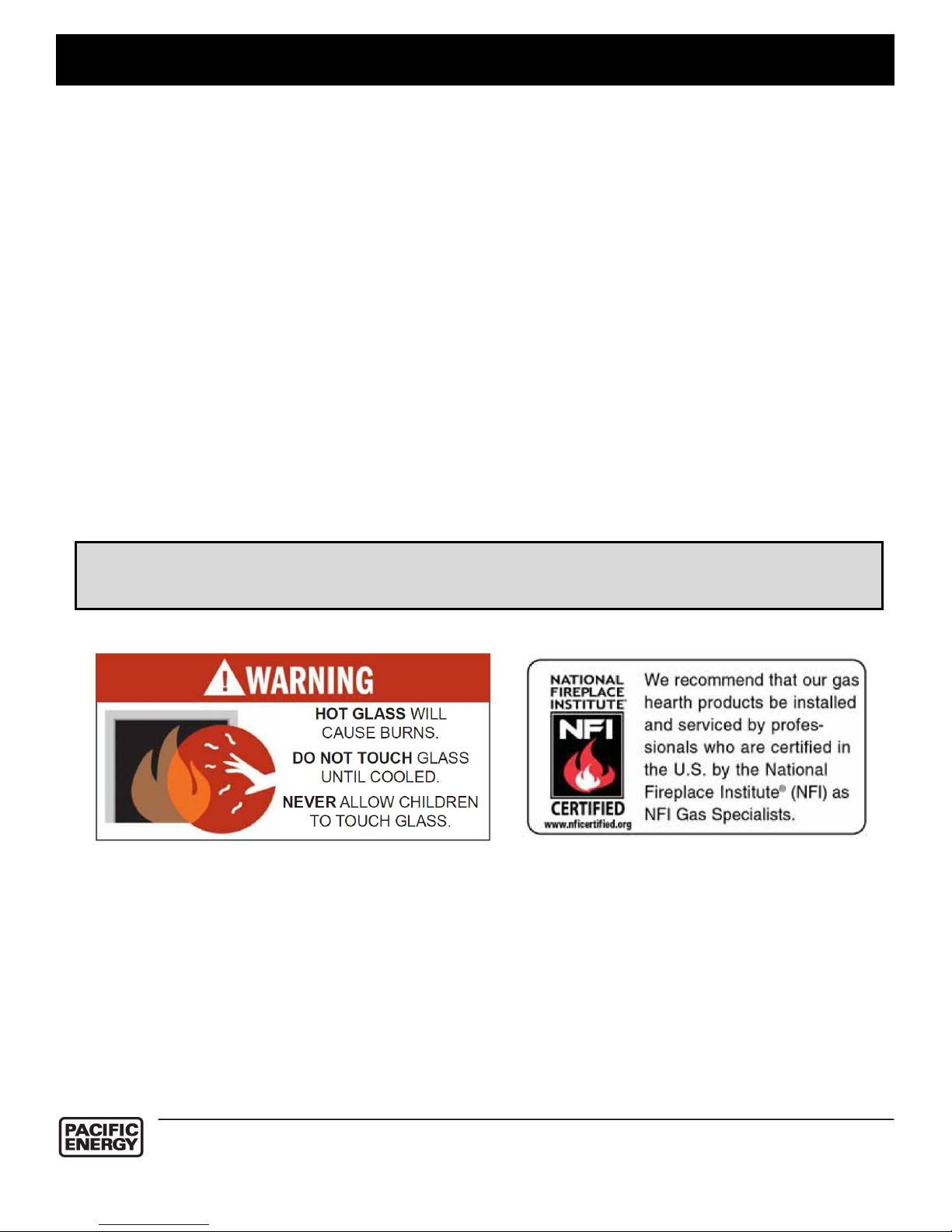
A barrier designed to reduce the risk of burns from the hot viewing glass is provided with
the appliance and shall be installed.
If the barrier becomes damaged, the barrier shall be replaced with the manufacturers
barrier for this appliance.
Any grill, panel or door removed for servicing the unit must be replaced prior to operating.
Installation and repair should be done by a qualified service person. The appliance should
be inspected before use and at least annually by a professional service person. More
frequent cleaning may be required due to excessive lint from carpeting, bedding material,
etc. It is imperative that control compartments, burners and circulating air passageways of
the appliance be kept clean.
This appliance must not be connected to a chimney flue serving a separate solid fuel
burning appliance.
It is our policy that no responsibility is assumed by the Company or by any of its
employees or representatives for any damages caused by an inoperable, inadequate, or
unsafe condition which is the result, either directly or indirectly, of any improper operation
or installation procedures.
Safety
5

OWNER’S
INFORMATION
Congratulations on your purchase of a Pacific Energy Gas Fireplace.
Your fireplace has been professionally installed by:
Dealer name: ___________________
Phone Number: _________________
If you discover any problems with your gas fireplace contact your dealer immediately to have the
unit repaired.
Caution: Do not attempt to repair the fireplace because you may cause injury to yourself or others,
and risk causing damage to the unit.
Before operating your fireplace carefully read this manual and pay close attention to all Safety
Warnings. The manual contains important information on the unit’s safe operation and
maintenance.
When lit for the first time, the fireplace will emit a slight odour for a couple of hours. This is due to
the curing of paints, sealants, gaskets, and lubricants used in the manufacturing process. This
condition is temporary. Open doors and windows to ventilate the area. Odour caused by the curing
process may cause discomfort to some individuals.
It is normal for fireplaces fabricated from steel to give off some expansion and/or contraction
noises during the start up or cool down cycle. Similar noises are found with your furnace heat
exchanger or cook stove oven.
First Fire
6
OWNER’S
INFORMATION
Remote Control Operation
Important
The Proflame Transmitter is an integrated part of the Proflame System, which consists of:
• Proflame Transmitter, to be used in conjunction with
• Integrated Fireplaces Control (Proflame IFC)
The Proflame Transmitter provides for controlling the following hearth appliance functions:
1. Main Burner On/Off
2. Main Burner flame modulation (6 levels)
3. Choice of standing or intermittent pilot (CPI/IPI)
4. Thermostat and Smart thermostat functions
5. Accent light modulation (6 levels)
6. Split flow valve
7. Comfort Fan speed modulation (6 levels)
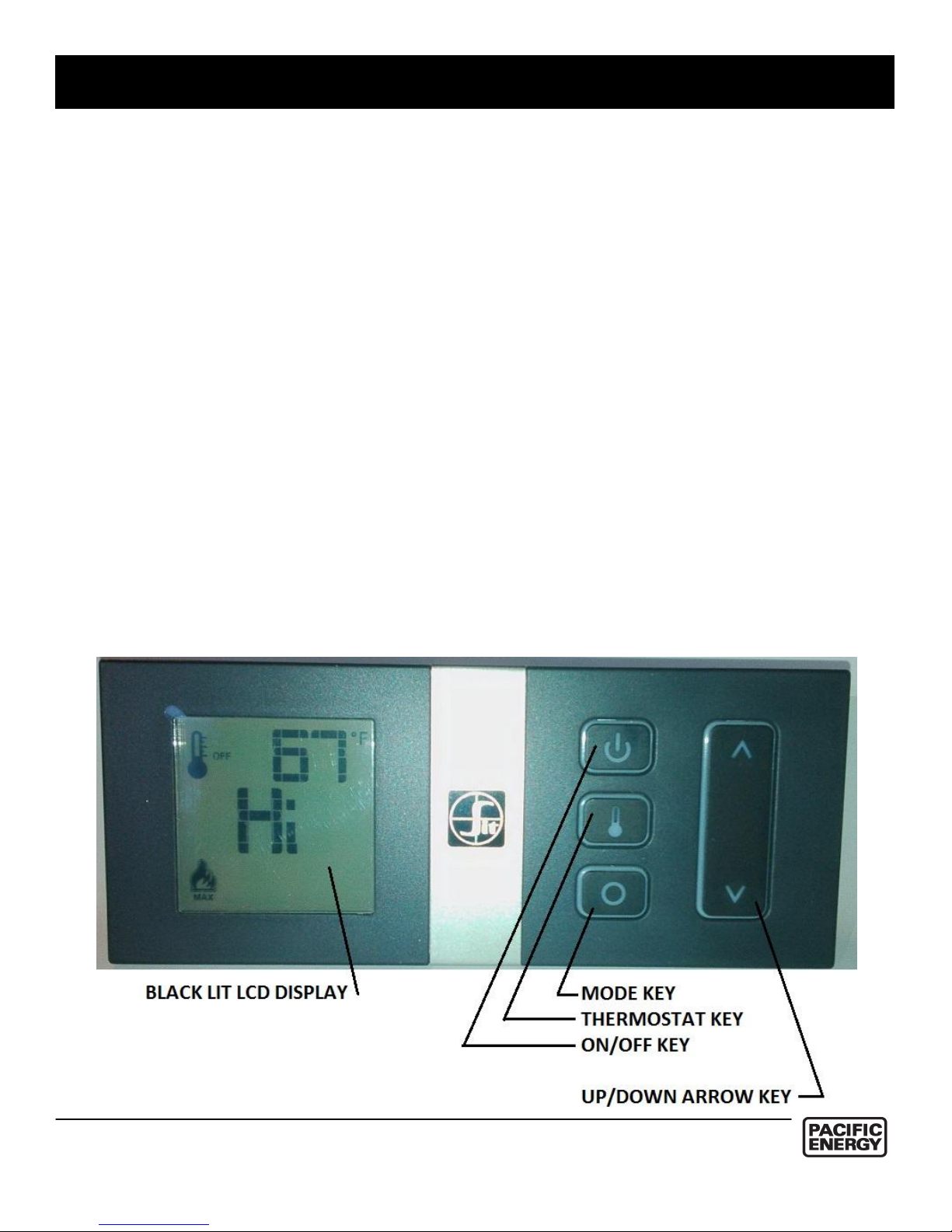
Transmitter (Remote Control with LCD Display)
The Proflame Transmitter uses a streamline design with a simple button layout and informative
LCD display (Fig. 1). A Mode Key is provided to index between the features and a Thermostat Key
is used to turn on/off or index through Thermostat functions (Fig. 1 & 2). Additionally, a Key Lock
feature is provided (Fig. 20).
Figure 1
`
7
OWNER’S
INFORMATION
Technical Data
Remote Control
Supply voltage 4.5 V (three AAA LR03 1.5 V batteries)
Ambient temperature ratings 0 - 50 °C (32 - 122 °F)
Typical operative distance in free air 12 m
Radio frequency 315 MHz ( FCC version )
433.92 MHz ( CE version )
WARNING
THE TRANSMITTER AND RECEIVER ARE RADIO FREQUENCY DEVICES.
PLACING THE TRANSMITTER IN OR NEAR METAL MAY SEVERELY REDUCE THE
SIGNAL RANGE.
METALLIC STRUCTURES OR RADIO INTERFERENCES CAN REDUCE THE OPERATIVE DISTANCE
OF THE DEVICE DEPENDING ON TYPE OF FIREPLACE, INSTALLATION AND ENVIROMENT.
ATTENTION!
- TURN “OFF” THE MAIN GAS SUPPLY OF THE APPLIANCE DURING INSTALLATION OR
MAINTENANCE OF THE RECEIVER DEVICE.
- TURN “OFF” MAIN GAS SUPPLY TO THE APPLIANCE PRIOR TO REMOVING OR
REINSERTING THE BATTERIES.
- IN CASE OF REMOTE CONTROL MALFUNCTION TURN OFF THE IFC DEVICE USING
THE “ON/OFF” MAIN SWITCH.
- FOR INSTALLATION/MAINTENANCE SWITCH OFF THE IFC DEVICE REMOVING MAIN
POWER SUPPLY PLUG.
- THE DEVICE IS NOT SUITABLE FOR THE USE OF RECHARGABLE BATTERIES AND ITS
OPERATIVE DISTANCE IS REDUCED WITH LOW BATTERY LEVEL.
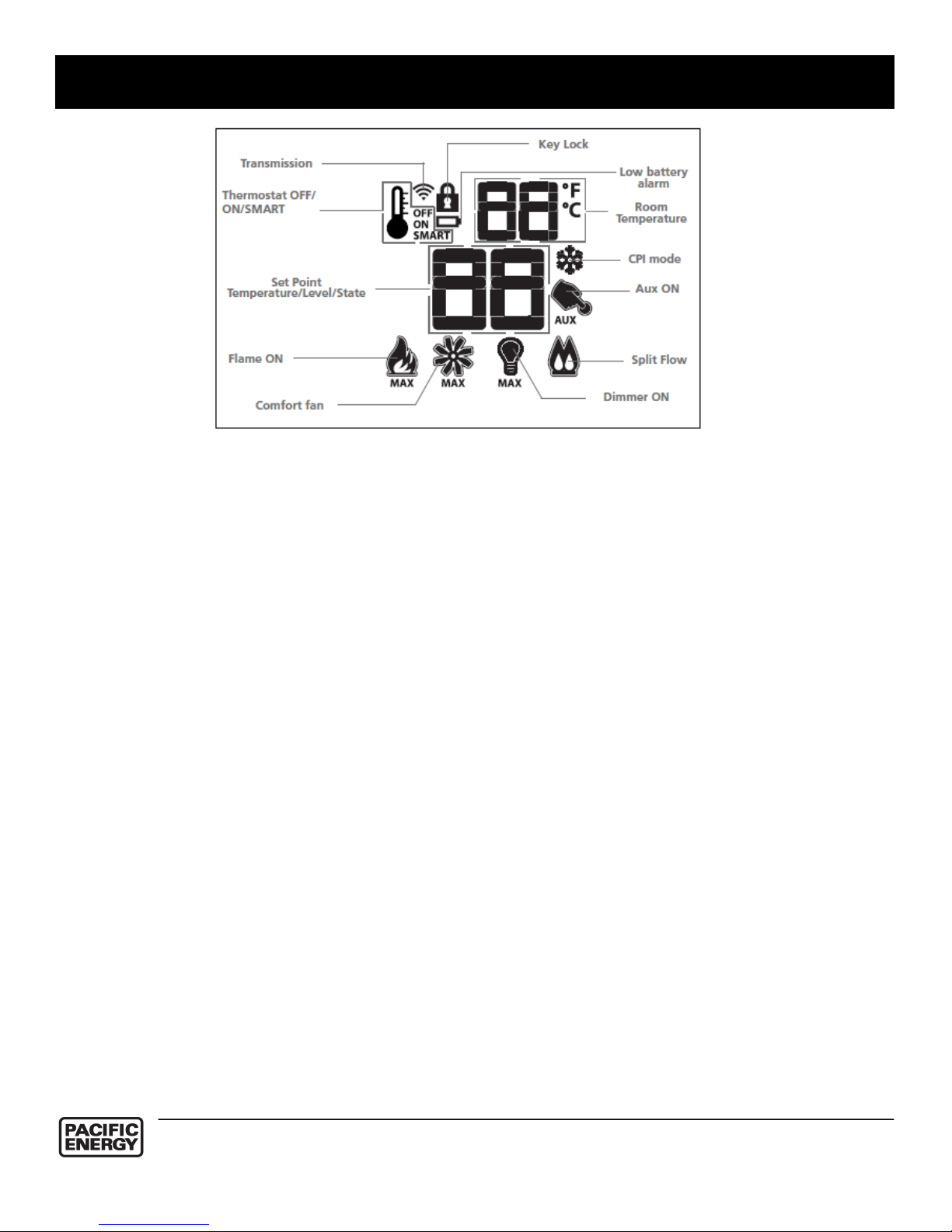
Figure 2
8
OWNER’S
INFORMATION
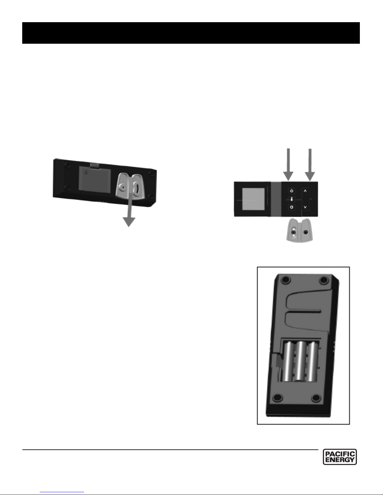
Wall mounting
The Proflame remote control is supplied with an adapter for wall mounting.
Install the controller 1.5 m above floor level, well away from heat sources, kitchens, doors or
windows.
Metallic structures or radio interferences can reduce the operative distance of the device.
Make sure to attach the adapter in a level plane without any distortion. Proceed as follows:
• Detach the adapter from the body of the remote control; see Fig. A.
• Position the adapter on the wall, mark the points for the fixing holes and drill the wall.
• Fix the adapter on the wall using the mounting hardware supplied with the remote control.
• Insert the remote control onto the adapter as shown in Fig. B.
Figure A: Detach the adapter from the body
Figue B: Adapter and remote control
OPERATING PROCEDURE
Initializing the System for the first time
Power the receiver. Activate the procedure of the receiver
address programming, see the receiver instruction (*).
The Receiver will “beep” three (3) times to indicate that
it is ready to synchronize with a Transmitter. Install the
3 AAA type batteries in the Transmitter battery bay, located
on the base of the Transmitter. (Fig. 3) With the batteries
already installed in the Transmitter, push the On button.
The Receiver will “beep” four times to indicate the
Transmitter’s command is accepted and sets to the particular
code of that Transmitter. The system is now initialized.
(*) The receiver may be independent or integrated to the IFC hearth
appliance control module. The receiver instruction may not be
independent when part of the IFC.
Figure 3
9
OWNER’S
INFORMATION
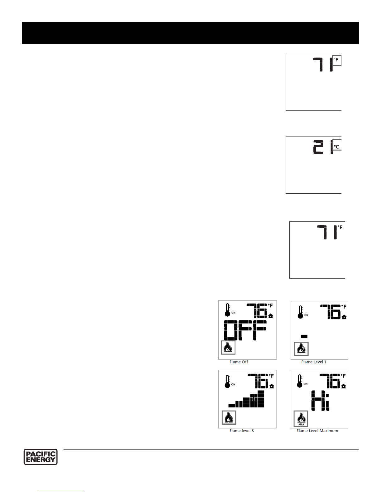
Remote Flame Control
The Proflame has six (6) flame levels. With the
system on, and the flame level at the maximum in
the appliance, pressing the down arrow key once
will reduce the flame height by one step until the
flame is turned off.
The Up Arrow Key will increase the flame height
each time it is pressed. If the Up Arrow Key is
pressed while the system is on but the flame is off,
the flame will come on in the high position. (Fig. 7)
A single “beep” will confirm reception of the
command.
Temperature indication Display
With the system in the “OFF” position, press the Thermostat Key and the
Mode Key at the same time. Look at the LCD screen on the transmitter to
verify that a C or F is visible to the right of the Room Temperature
display. (Fig. 4 & 5)
Turn on the Appliance
With the system OFF, press the ON/OFF Key on the
Transmitter. The Transmitter display will show some other
active Icons on the screen. At the same time the Receiver
will activate the appliance. A single “beep” from the
Receiver will confirm reception of the command.
Turn off the Appliance
With the system ON, press the ON/OFF Key on the
Transmitter. The Transmitter LCD display will only show
the room temperature (Fig. 6). At the same time the
Receiver will turn off the appliance. A single “beep” from
the Receiver confirms reception of the command.
Figure 7:
Figure 4: Display in Fahrenheit
Figure 5: Display in Celsius
Figure 6: Remote Control Display
10

OWNER’S
INFORMATION
ROOM THERMOSTAT (Transmitter Operation)
The Remote Control can operate as a room thermostat. The thermostat
can be set to a desired temperature to control the comfort level in a
room.
To activate this function, press the Thermostat key (Fig. 1). The LCD
display on the transmitter will change to show that the room thermostat
is “ON” and the set temperature is now displayed (Fig.8). To adjust the
set point, press the up or down arrow keys until the desired set point
temperature is displayed on the LCD screen of the transmitter.
Smart Thermostat (Transmitter Operation)
The Smart Thermostat function adjusts the flame height in accordance
to the difference between the set point and the room temperatures. As
the room temperature gets closer to the set point the Smart Function will
modulate the flame down. If the room temperature is cool the Smart
function will modulate the flame up. To activate this function, press the
thermostat key (Fig. 1) until the word "SMART" appears to the right of
the temperature bulb graphic (Fig. 9). To adjust the set point, press the
up or down arrow keys until the desired set point temperature is
displayed on the LCD screen of the transmitter (Fig. 10).
Note. When Smart Thermostat is activated, the manual flame height
Fan Speed Control
If the appliance is equipped with a hot air circulating fan, the speed of the fan can be controlled by
the Proflame system. The fan speed can be adjusted through six (6) speeds. To activate this
function use the Mode Key (Fig.1) to index to the fan control icon (Fig. 11). Use the Up/Down Arrow
Keys (Fig.1) to turn on, off or adjust the fan speed (Fig. 12). A single “beep” will confirm reception of
the command.
Figure 11
Figure 12
Figure 8
Figure 9: Smart Flame
Function
Figure 10
11
 Loading...