

Pacific energy fusion gas, A Installation And Operating Instructions Manual
070905-28 FSGA 5056.4221
INSTALLATION
and
OPERATING
INSTRUCTIONS
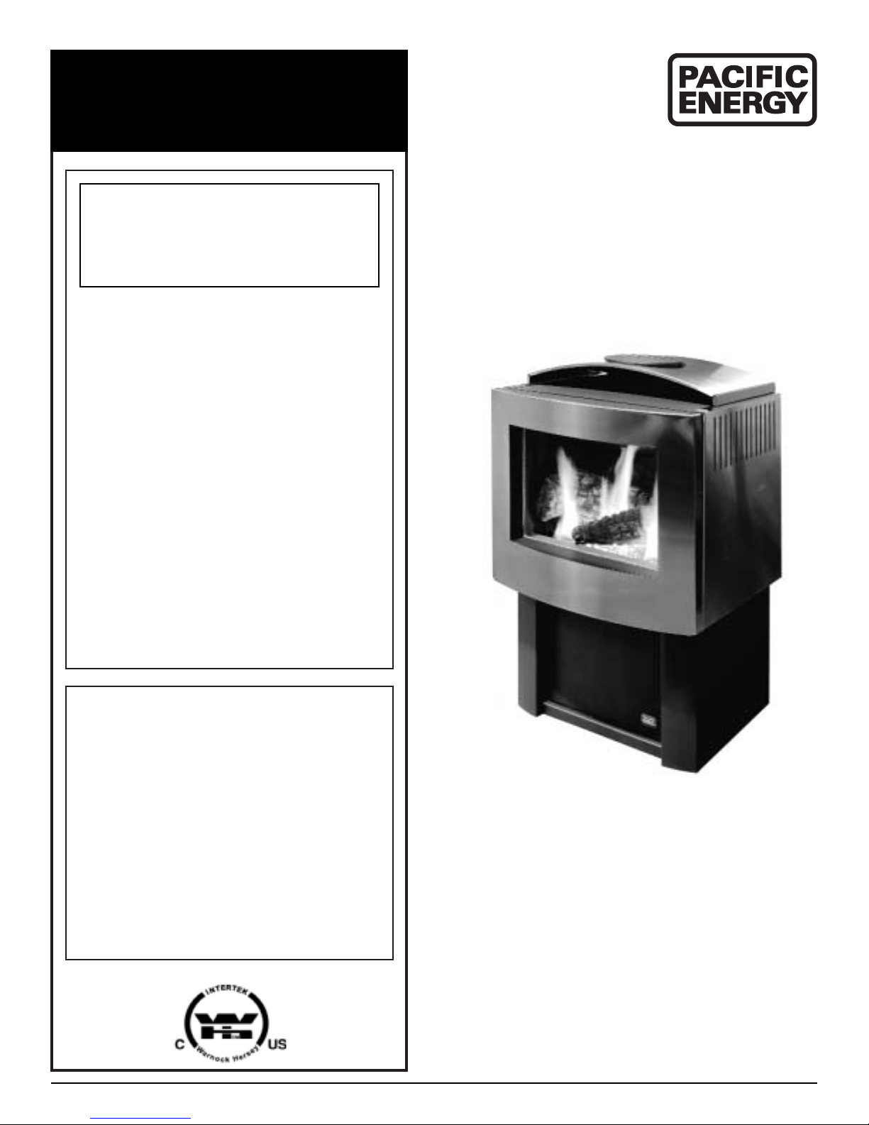
fusion gas
DIRECT VENT
FREESTANDING STOVE
Series A
IMPORTANT:
THESE INSTRUCTIONS ARE TO
REMAIN WITH THE HOMEOWNER
– Do not store or use gasoline or
other flammable vapours and
liquids in the vicinity of this or
any other appliance.
– WHAT TO DO IF YOU SMELL GAS
• Do not try to light any appliance
• Do not touch any electrical
switch; do not use any phone in
your building
•Immediately call your gas supplier
from a neighbour’s phone. Follow
the gas supplier’s instructions
• If you cannot reach your gas
supplier, call the fire depar tment
– Installation and service must be
performed by a qualified installer,
service agency or the gas supplier.
This appliance may be installed in
an aftermarket permanently
located, manufactured home (USA
only) or mobile home, where not
prohibited by local codes.
This appliance is only for use with
the type of gas indicated on the
rating plate. This appliance is not
convertible for use with other
gases, unless a certified kit is
used.
WARNING: If the information in
these instructions is not followed
exactly, a fire or explosion may
result causing property damage,
personal injury or loss of life.

2
070905-28 FSGA 5056.4221
CAUTION . . . . . . . . . . . . . . . . . . . . . . . . . . . . . . . . . . . . . . . . . . . . . . . . . . .3
SAFETY . . . . . . . . . . . . . . . . . . . . . . . . . . . . . . . . . . . . . . . . . . . . . . . . . . . .4
MAINTENANCE . . . . . . . . . . . . . . . . . . . . . . . . . . . . . . . . . . . . . . . . . . . . . .4
GAS SUPPLY . . . . . . . . . . . . . . . . . . . . . . . . . . . . . . . . . . . . . . . . . . . . . . . .5
FLOOR PROTECTION . . . . . . . . . . . . . . . . . . . . . . . . . . . . . . . . . . . . . . . . .5
ATTACHMENT TO FLOOR . . . . . . . . . . . . . . . . . . . . . . . . . . . . . . . . . . . . . .5
CLEARANCES . . . . . . . . . . . . . . . . . . . . . . . . . . . . . . . . . . . . . . . . . . . . . . .5
TOP OR REAR VENT CONVERSION . . . . . . . . . . . . . . . . . . . . . . . . . . . .6-9
VENTING REQUIREMENTS . . . . . . . . . . . . . . . . . . . . . . . . . . . . . . . . . . . .10
WALL TERMINATION VENTING- with no vertical rise . . . . . . . . . . . . . . . .10
WALL TERMINATION VENTING- with vertical rise . . . . . . . . . . . . . . . . . .11
ROOF TERMINATION VENTING . . . . . . . . . . . . . . . . . . . . . . . . . . . . . . . . .12
VENT TERMINAL CLEARANCES . . . . . . . . . . . . . . . . . . . . . . . . . . . . . . . .13
VENTING SYSTEM COMPONENTS . . . . . . . . . . . . . . . . . . . . . . . . . . . . . .13
REMOVAL OF WINDOW FRAME . . . . . . . . . . . . . . . . . . . . . . . . . . . . . . . .15
REMOVAL OF RIGHT HAND SIDE PANEL . . . . . . . . . . . . . . . . . . . . . . . . .15
ADJUSTMENT OF TOP VENT DAMPER . . . . . . . . . . . . . . . . . . . . . . . . . . .16
LOG SET INSTALLATION . . . . . . . . . . . . . . . . . . . . . . . . . . . . . . . . . . . . .17
LIGHTING INSTRUCTIONS . . . . . . . . . . . . . . . . . . . . . . . . . . . . . . . . . . . .18
FIRST FIRE . . . . . . . . . . . . . . . . . . . . . . . . . . . . . . . . . . . . . . . . . . . . . . . .19
MANUAL OPERATION . . . . . . . . . . . . . . . . . . . . . . . . . . . . . . . . . . . . . . . .19
OPTIONAL REMOTE CONTROL . . . . . . . . . . . . . . . . . . . . . . . . . . . . . . . .20
OPTIONAL BLOWER . . . . . . . . . . . . . . . . . . . . . . . . . . . . . . . . . . . . . . . . .21
PROPANE CONVERSION . . . . . . . . . . . . . . . . . . . . . . . . . . . . . . . . . . .22-23
BODY REPLACEMENT PARTS . . . . . . . . . . . . . . . . . . . . . . . . . . . . . . . . .24
BURNER REPLACEMENT PARTS . . . . . . . . . . . . . . . . . . . . . . . . . . . . . . .25
SAFETY LABEL . . . . . . . . . . . . . . . . . . . . . . . . . . . . . . . . . . . . . . . . . . . . .26
NOTES . . . . . . . . . . . . . . . . . . . . . . . . . . . . . . . . . . . . . . . . . . . . . . . . . . . .27
Contents
3
070905-28 FSGA 5056.4221
FOR Y OUR SAFETY
Do not install or operate your Pacific
Energy heater without first reading
and understanding this manual. Any
installation or operational deviation
from the following instructions voids
the Pacific Energy Warranty and may
prove hazardous.
This appliance and its individual
shutoff valve must be disconnected
from gas supply piping system during
any pressure testing of that system at
test pressures in excess of 1/2 psig.
(3.5 kpa).
This appliance must be isolated from
the gas supply piping system by
closing its individual manual shutoff
valve during any pressure testing of
the gas supply piping system at test
pressures equal to or less than 1/2
psig. (3.5 kPa).
This appliance must not be
connected to a chimney flue serving
a separate solid-fuel burning
appliance.
If the optional blower is installed, this
appliance must be electrically grounded in accordance with local codes or,
in the absence of local codes, with
the National Electrical Code,
ANSI/NFPA 70, or the Canadian
Electrical Code, CSA C22.1.
Important: When lit for the first time, the appliance will emit a slight
odour for a couple of hours.This is due to the curing of paints, sealants
and lubricants used in the manufacturing process.This condition is
temporary. Open doors and windows to ventilate area. If optional fan kit
has been installed, place fan in the "OFF" position. Smoke and fumes
caused by the curing process may cause discomfort to some
individuals.
It is normal for fireplaces fabricated of steel to give off some expansion
and/or contraction noises during the start up or cool down cycle. Similar
noises are found with your furnace heat exchanger or cook stove oven.
Caution
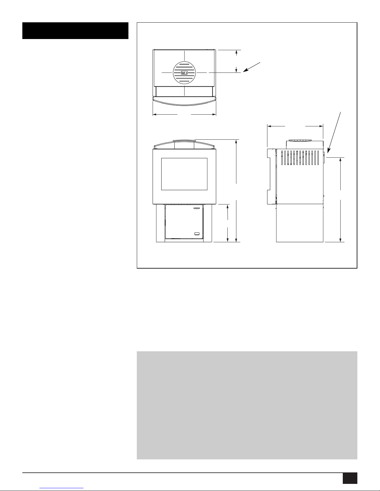
Fig. #1
7 5/8”
34”
18 5/8”
12 9/16”
26 7/16”
21”
Stove Dimensions
Center of top flue outlet
Center of rear
flue outlet
4
070905-28 FSGA 5056.4221
• Due to high temperatures, this gas
appliance should be located out of
traffic and away from furniture and
draperies.
• Children and adults should be
alerted to the hazards of high surface
temperatures and should stay away
to avoid burns or clothing ignition.
• Young children should be carefully
supervised when they are in the
same room as the appliance.
• Clothing or other flammable material
should not be placed on or near the
appliance.
• Under no circumstances should this
fireplace be modified. Any grill, panel
or door removed for servicing the unit
must be replaced prior to operating.
Failure to do so may create a
hazardous condition.
• Installation and repair should be
done by a qualified service person.
The appliance should be inspected
before use and at least annually by a
professional service person. More
frequent cleaning may be required
due to excessive lint from carpeting,
bedding material, etc. It is imperative
that control compartments, burners
and circulating air passageways of
the appliance be kept clean.
It is Pacific Energy’s policy that no
responsibility is assumed by the
Company or by any of its employees
or representatives for any damages
caused by an inoperable, inadequate,
or unsafe condition, which is the
result, either directly or indirectly, of
any improper operation or installation
procedures.
Caution: Turn off gas and electrical
power supply and allow ample time
for unit to cool before servicing
appliance. It is recommended that
this appliance and venting should be
inspected at least once a year by a
qualified service person.
Do not use this heater if any part has
been under water.Immediately call a
qualified service technician to inspect
the heater and to replace any part of
the control system or gas control,
which has been under water.
Door Glass
Warning: Do not operate appliance
with glass panel removed, cracked
or broken. Replacement of glass
should be done by a licensed or
qualified service person.
Do not strike or otherwise impact the
glass in anyway that may cause it to
break. If the glass becomes cracked
or broken, it must be replaced before
using the fireplace. Replacement
glass can be obtained from your
nearest Pacific Energy dealer. Use
ceramic glass only. Do not substitute
with any other type.The size required
is 12 3/16” x 17 1/4” x 5 mm.
To remove broken glass, see page 11
for window removal instructions.
Remove all particles of glass. Be
careful, as they are very sharp. Install
new glass complete with gasket and
frame.
Annual Inspection:
a) Clean air passageways of
excessive lint and dust buildup from
carpeting, bedding material, etc.
The flow of ventilation air must not
be obstructed.
b) Inspect logs and burner
assembly for lint and soot build-up.
If excessive build-up of soot is present, have a qualified service person
inspect and adjust unit for proper
combustion. Clean logs and burner
with a vacuum cleaner, paying close
attention to the ports on the burner.
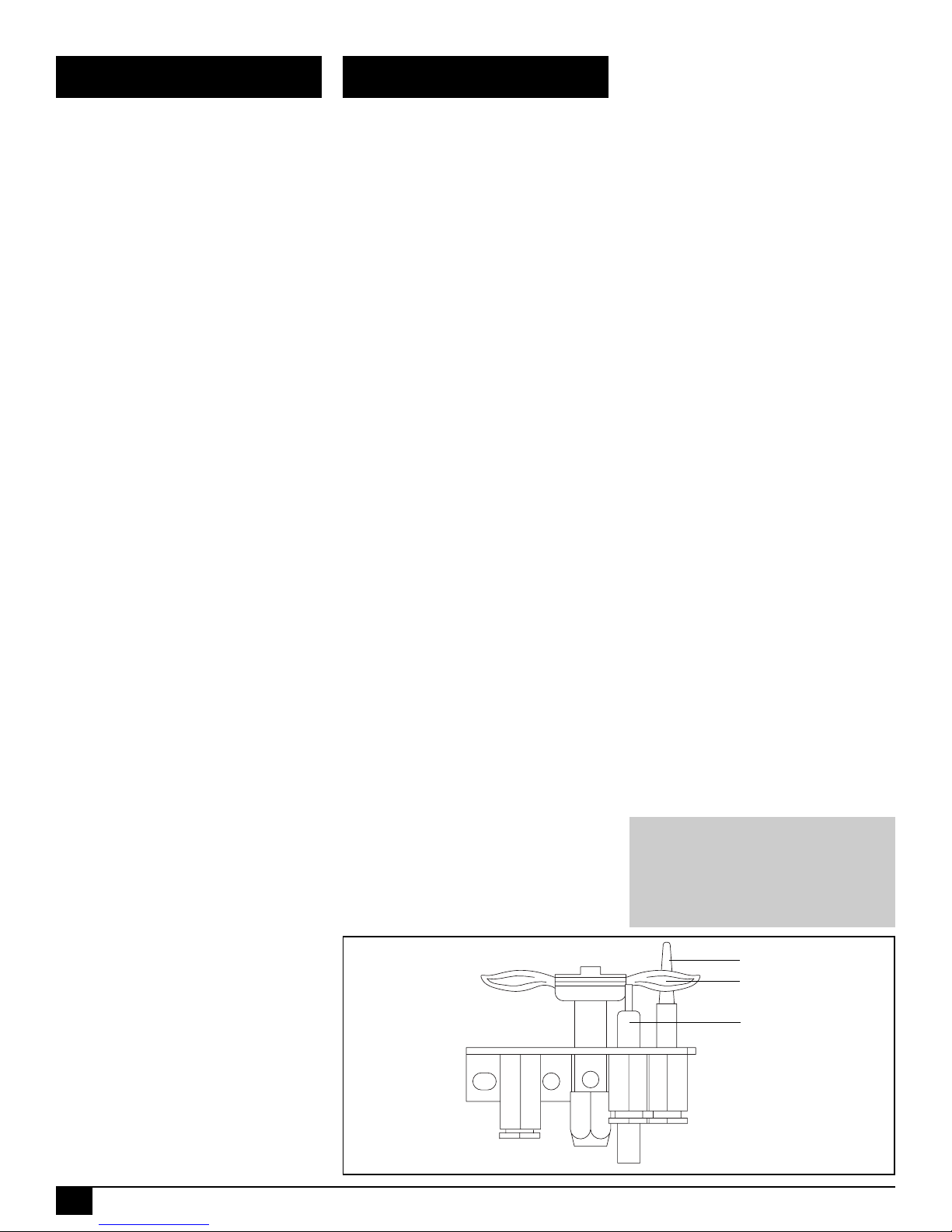
c) Check the pilot system for proper
flame size and operation. Clean
pilot free of lint and dust.
(See Fig. #2)
d) Check that the vent pipe and
vent terminal are open and free
from blockage or debris. If the
venting system is disassembled for
cleaning, it must be properly
assembled and re-sealed, as per
vent manufacturers instructions.
e) Check door and glass panel
gasket, replace if necessary. It is
important that the glass and door
seal be maintained in good
condition.
Note: The appliance area must be
kept clear and free from
combustible materials, gasoline and
other flammable vapours and
liquids.
Periodically:
a) Viewing glass may be cleaned
with fireplace glass cleaner.
b) Exterior finish may be cleaned
with mild soap and water.
Safety Maintenance
Fig. #2
THERMOCOUPLE
ELECTRODE
PILOT FLAME
Caution:
Do not use abrasive cleaners
on glass or any other part of
this appliance.
Do not clean glass when hot.
5
070905-28 FSGA 5056.4221
Gas Supply
Floor Protection
Clearances
Attachment
to Floor
In the state of Massachusetts, only a
licensed plumber and gas fitter may
install this product. Correct gas line
diameter must be used to assure
proper operation.
The gas control is equipped with a
captured screw type pressure test
point, therefore it is not necessary to
provide a 1/8 inch N.P.T. plugged
tapping pressure test port for
checking gas pressure immediately
upstream of the gas supply
connection to the appliance.
The gas valve inlet accepts a 3/8"
N.P.T. fitting.
Mobile Home installations require that
the appliance be firmly attached to
the structure. Once the appliance is in
its final location, secure the unit in
place through holes in the pedestal
base.The holes are located on the
left and right hand side of the base.
The Fusion Gas stove may be
installed directly on a combustible
floor.If the appliance is to be installed
directly on carpeting, combustible
floor tile or other combustible material
other than wood flooring, the
appliance shall be installed on a
metal or wood panel extending the
full width and depth of the unit.
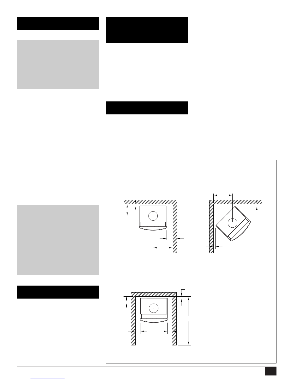
The minimum clearances from the
appliance to combustibles are shown
on Fig. #3. Adequate clearances
around air openings are required.
Sidewall to Appliance 6 in (152 mm)
Rearwall to Appliance 1 in (25 mm)
Corner to Appliance 1 in (25 mm)
Alcove Sidewall to Appliance 6 in (152 mm)
Alcove minimum width 33 in (838 mm)
Alcove maximum depth 48 in (1219 mm)
Alcove minimum height 46 in (1168 mm)
Minimum Clearances to Combustibles
Correct gas pressure requirements
Natural Gas Propane
Min. Pressure 5.0” WC 11.5” WC
(For purpose of
input adjustment)
Max. Pressure 13.9” WC 13.9” WC
Manifold Pressure
Maximum 3.8” WC 10.5” WC
Minimum 0.7” WC 1.6” WC
13 3/4”
1”
1”
Fig. #3
Caution:
The gas line should be installed
by a qualified service person in
accordance with all building
codes. Consult local and/or
national building codes before
proceeding.
1”
8 5/8”
16 1/2”
6”
8 5/8”
1”
6”
ALCOVE HEIGHT
61” MINIMUM
6”
48”
6
070905-28 FSGA 5056.4221
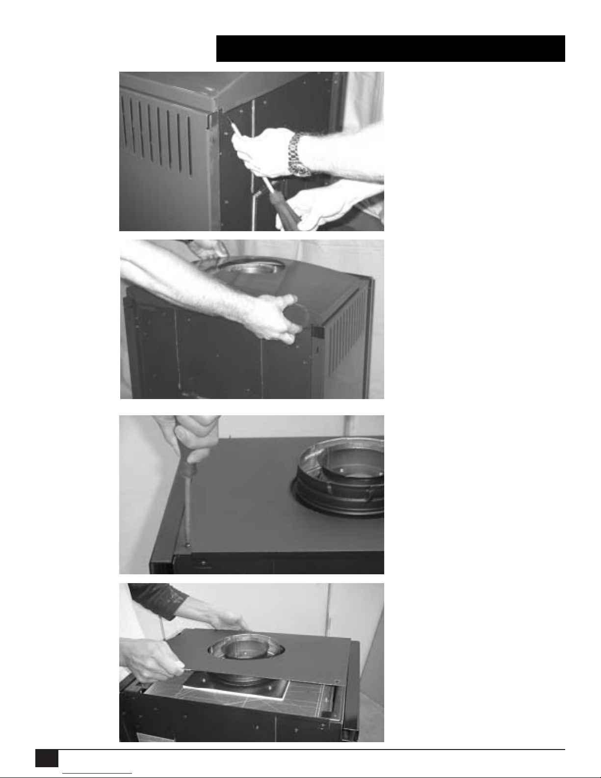
Top or Rear Vent Conversion
1) Remove the two screws securing
the air deflector to the rear of the
stove (Fig.#3.01), remove the air
deflector and store it in a safe place
(Fig. #3.02).
2) Remove the two screws that
secure the top plate in place
(Fig. #3.03). To remove the top plate,
lift it from the back and slide it forward slightly to unhook it from the
brackets at the front (Fig.#3.04).
The fusion gas stove is set up in the
factory as a top vent.To convert to
rear vent, use the following procedure. Please read the instructions
carefully before converting the appliance:
Fig. #3.01
Fig. #3.02
Fig. #3.03
Fig. #3.04
7
070905-28 FSGA 5056.4221
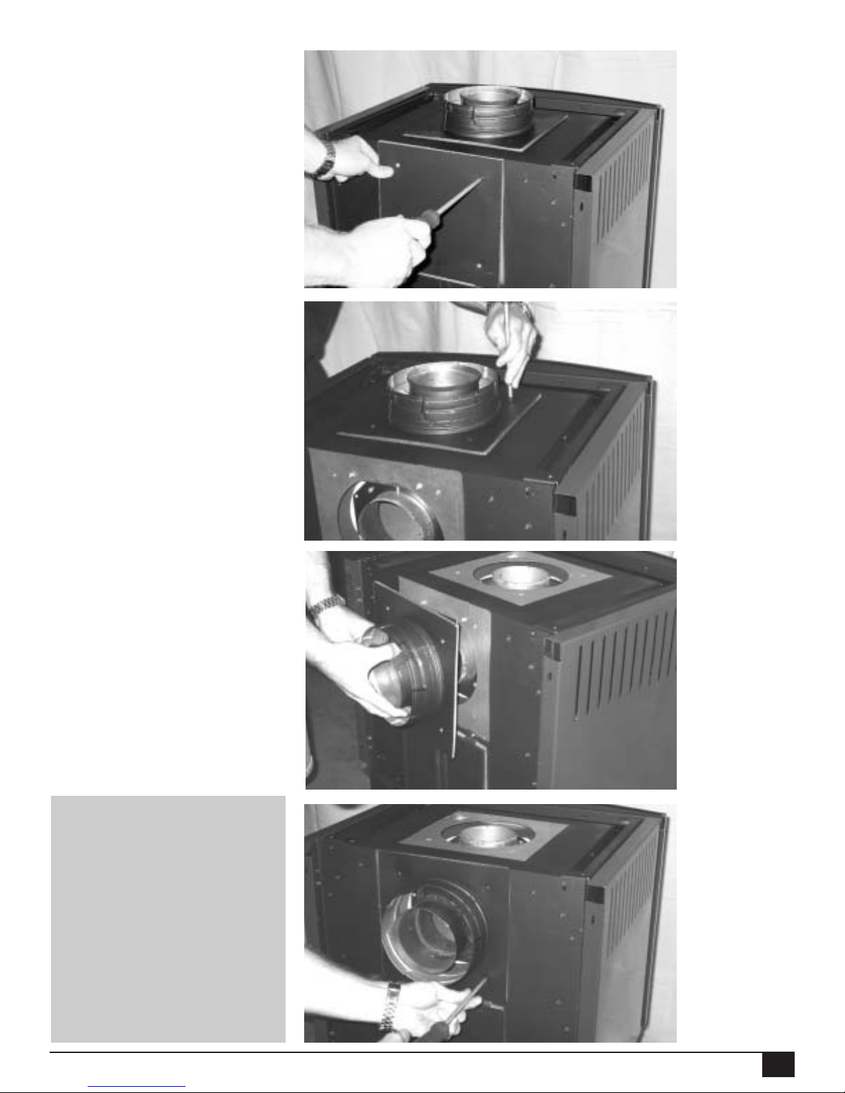
IMPORTANT:
Take care not to damage the
gaskets on the vent adapter
and flue outlet cover plate
during the procedure. Inspect
the gaskets carefully before
reinstalling, if the gasket on
either piece is damaged, it
will need to be replaced
before continuing.
3) Remove the four screws that fasten the vent cover to the back of the
appliance, and remove the vent cover
(Fig. #3.05).
4) Remove the four screws securing
the vent adapter to the top of the
stove (Fig #3.06).Pull the vent
adapter off and attach it to the rear
flue outlet. Press fir mly to ensure a
positive, snug connection (Fig.#3.07)
and use four screws to fasten it in
place (Fig. #3.08).
Fig. #3.05
Fig. #3.06
Fig. #3.07
Fig. #3.08
8
070905-28 FSGA 5056.4221
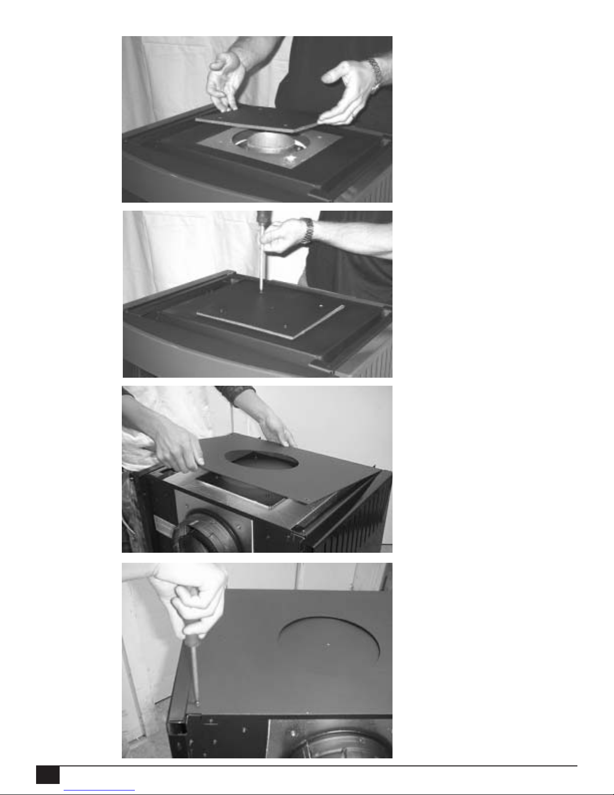
5) Place the vent cover from step 3
over the top flue outlet (Fig. #3.09)
and use four screws to fasten it in
place (Fig. #3.10).
6) Replace the top plate by hooking
the front flange over the mounting
brackets (Fig.#3.11) pull it firmly
towards the rear of the appliance and
fasten it down at the back with two
screws (Fig #3.12).
Fig. #3.09
Fig. #3.10
Fig. #3.11
Fig. #3.12
9
070905-28 FSGA 5056.4221
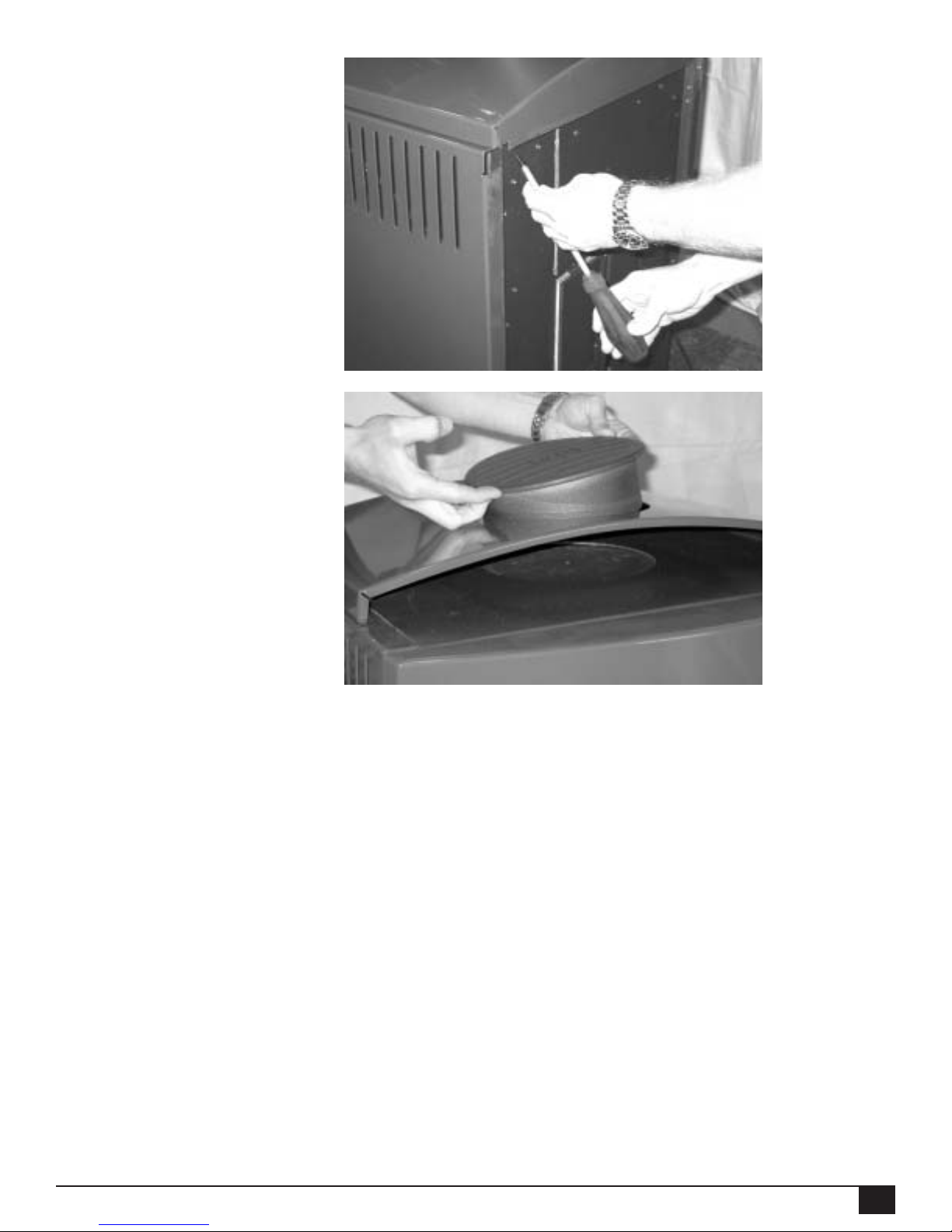
7) Place the air deflector back on the
top of the appliance and align it so it
is spaced evenly from either side.
Fasten the air deflector to the rear
bracket using two screws (Fig. #3.13).
8) Place the optional cast iron Fusion
Gas Trivet into the outlet of the air
deflector.Take care to not scratch the
finish on the top of the appliance (Fig.
#3.14). Adjust the cap so that the
logo reads left to right when facing
the front of the appliance, and the
radius matches the top of the air
deflector.
Fig. #3.13
Fig. #3.14
 Loading...