

Pacific energy A, Fairfield Operating Instructions Manual
WARNING: If the information in this
manual is not followed exactly, a fire or
explosion may result causing property
damage, personal injury or loss of life.
-- Do not store or use gasoline or other
flammable vapors and liquids in the vicinity
of this or any other appliance.
-- WHAT TO DO IF YOU SMELL GAS
- Do not try to light any appliance.
- Do not touch any electrical switch; do
not use any phone in your building.
- Immediately call your gas supplier
from a neighbour’s phone. Follow the
gas supplier’s instructions.
- If you cannot reach your gas supplier,
call the fire department.
-- Installation and service must be
performed by a qualified installer, service
agency or the gas supplier.
IMPORTANT:
THESE INSTRUCTIONS ARE TO
REMAIN WITH THE
HOMEOWNER
SERIES A
VENTED GAS FIREPLACE
HEATER
INSTALLATION
AND
OPERATING
INSTRUCTIONS
Fairfield
Gas Insert
090701-24 Fairfield-A 5056.425
Printed in Canada
Pacific Energy Fireplace Products Ltd.
Box 1060, Duncan, BC V9L 3Y2
Phone: 250-748-1184
Web site: http://www.pacificenergy.net
f i r e - p a r t s . c o m
2
Contents
Caution ...................................................................................................... 3
Maintenance .............................................................................................. 4
Installation................................................................................................. 5
Clearances ................................................................................................. 6
Venting....................................................................................................... 7
Gas Supply ................................................................................................ 7
Blocked Vent Shut-off System ................................................................. 8
Draft Inspection ........................................................................................ 8
Surround Assembly .................................................................................. 9
Log Set ..................................................................................................... 10
Glowing Embers ..................................................................................... 12
Levelling Legs ......................................................................................... 12
Glass Frame Installation ........................................................................ 12
Louver Installation ................................................................................. 13
Optional Radiant Overlay ..................................................................... 13
Lighting Instructions .............................................................................. 14
First Fire .................................................................................................. 15
Operation................................................................................................. 15
Primary Air Adjustment ........................................................................ 15
Burner Removal...................................................................................... 16
Propane Conversion ............................................................................... 17
Optional Blower ...................................................................................... 18
Replacement Parts .................................................................................. 20
Burner Replacement Parts .................................................................... 22
Label ........................................................................................................ 23
23
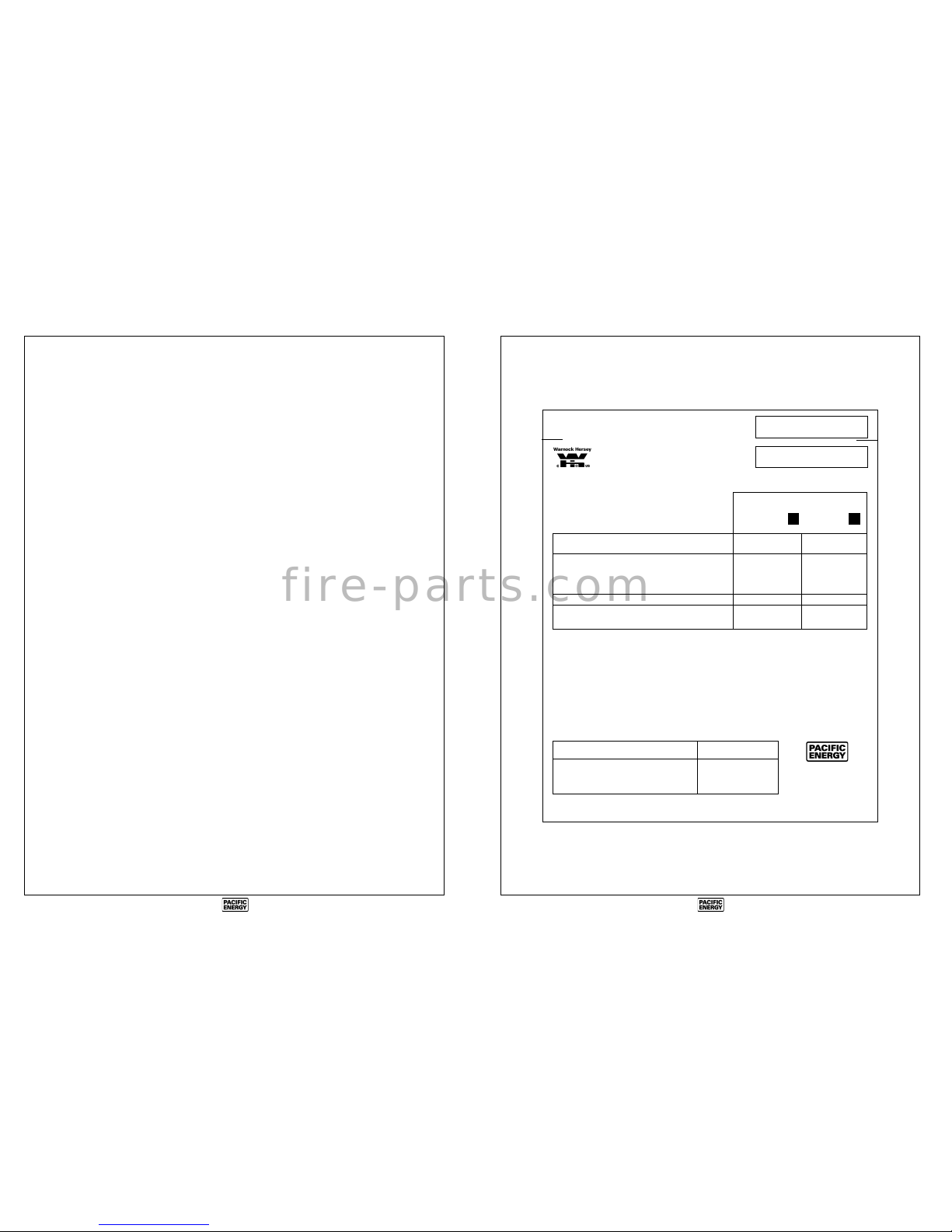
FOR USE WITH/ NATURAL GAS/ LP-GAS/
EN CASE D’EMPLOI AVEC:
DU GAZ NATUREL
DU GAZ LP
Minimum supply pressure / Pression minimum d’alimentation: 5.0 in/wc / 5.0 po/c.e. 12.5 in/wc / 12.5 po/c.e.
(For the purpose of input adjustment/dans le but de regler l’alimenation) (1.25 kPa) (3.11 kPa)
Manifold pressure / Pression de la tuyauterie: 3.8 in/wc / 3.8 po/c.e. 11.0 in/wc / 11.0 po/c.e.
(.95 kPa) (2.74 kPa)
Orifice Size / Diametre de l’injectuer: # 45 (2.08 mm) # 55 (1.32 mm)
Input BTU/hr (kW) / Puissance à l'entrée BTU/h (kW) : Max.: 21,000 (6.2) Max.: 21,000 (6.2)
Min.: 10,500 (3.1) Min.: 10,500 (3.1)
Optional components: Blower Kit (MINB.BLOW) / Éléments facultatifs: Ventilateur (MINB.BLOW)
Blower electrical rating: 115v, 60hz, 0.5 A / Normes electriques du ventilateur: 115v, 60hz, 0.5 A
This appliance equipped for altitudes 0-4500 ft. (0-1370 m) / Cet unité est concu pour des altitudes variant entre 0- 4500
pieds (0-1370 m). Also certified for installation in a bedroom or a bedsitting room / Aussi certifié pour installation dans
une chambre à coucher ou une salle de séjour.
This appliance needs fresh air for safe operation and must be installed so there are provisions for adequate combustion
and ventilation air. Par mesure de securite, cet appareil doit etre installe de facon a assurer un approvisionnement
suffisant d’air de combustion et de ventilation. This vented gas fireplace is not for use with air filters. Ne pas utiliser de
filtre à air avec foyer au gaz à évacuation.
WARNING: Improper installation, adjustment, alteration, service or maintenance can cause injury or property damage.
Refer to the owner’s information manual provided with this appliance. For assistance or additional information, consult a
qualified installer, service agency or the gas supplier.
This appliance must be installed in accordance with local codes, if any; if not, follow the current CAN/CGA-B149
(Canada) or ANSI Z223.1 (USA). Cet appareil diot etre installe conformement aux exigences des codes locaux. S’il
n’existe aucun code local, se conformer a la norme CAN/CGA-B149 en vigueur.
Left and Right side are determined when facing the front of the appliance.
Les cotes droit et gauche se determinent en se mettant devant l’appareil et en lui faisant face.
INSTALL IN SOLID FUEL BURNING FIREPLACE / N'INSTALLER QUE DANS UN FOYER NON COMBUSTIBLE
MINIMUM CLEARANCES TO COMBUSTIBLES / Fireplace Insert /
DEGAGEMENT DES MATIERES INFLAMMABLES Encart de la cheminée
Adjacent Sidewall / Mur du côté adjacent : 9.5 in. / 9.5 po. (241 mm)
Ceiling / Plafond : 38 in. / 38 po. (965 mm)
Mantel to Appliance / Du manteau al’appareil : 9 in. / 9 po. (229 mm)
Max. Mantel Extension / Extension max. dmanteau : 12 in. / 12 po. (305 mm)
Facing Side and Top / : 1 in. / 1 po. (25 mm)
040701 5050.7203 1-FFGA
PACIFIC ENERGY
FIREPLACE PRODUCTS LTD.
PO Box 1060, Duncan,
British Columbia, V9L 3Y2
MODEL / MODELE: FAIRFIELD - INSERT
SERIES / SERIE: A
ANSI Z21.88-1999b / CAN 2.33-M99 Vented Gas Fireplace
Heaters, CAN/CGA-2.17 -M91 Gas-Fired Appliances For Use
At High Altitudes
REPORT NO.
476-1936-00
L18582
VENTED GAS FIREPLACE HEATER - NOT FOR
USE WITH SOLID FUEL
FOYER AU GAZ À ÉVACUATION - NE PAS
UTILISER AVEC DU COMBUSTIBLE SOLIDE.
CERTIFIED FOR CANADA AND U.S.A. / CERTIFIÉ POUR CANADA ET U.S.A.
WH
WH
DO NOT REMOVE OR
COVER THIS LABEL
MADE IN CANADA / FABRIQUE AU CANADA
This Appliance is Equipped For Use With /
Cet Appareil est Équipé Pour Utilise Avec :
NATURAL GAS
GAZ NATUREL
LP-GAS
LP GAZ
Label
f i r e - p a r t s . c o m
3
IMPORTANT: When lit for the first time, the
appliance will emit a slight odor for a couple of
hours. This is due to the curing of paints, sealants and lubricants used in the manufacturing
process. This condition is temporary. Open doors
and windows to ventilate area. If optional fan
kit has been installed, place fan in the "OFF"
position. Smoke and fumes caused by the curing
process may cause discomfort to some individuals.
It is normal for fireplaces fabricated of steel to
give off some expansion and/or contraction
noises during the start up or cool down cycle.
Similar noises are found with your furnace heat
exchanger or cook stove oven.
Caution
FOR YOUR SAFETY - Do not install or operate your
Pacific Energy Fairfield Gas Insert without first reading and
understanding this manual. Any installation or operational
deviation from the following instructions voids the Pacific
Energy Fireplace Products Warranty and may prove hazardous.
This appliance and its individual shutoff valve must be
disconnected from the gas supply piping system during any
pressure testing of that system at test pressures in excess of
1/2 psig (3.5 kPa).
This appliance must be isolated from the gas supply piping
system by closing its individual manual shutoff valve during
any pressure testing of the gas supply piping system at test
pressures equal to or less than 1/2 psig (3.5 kPa).
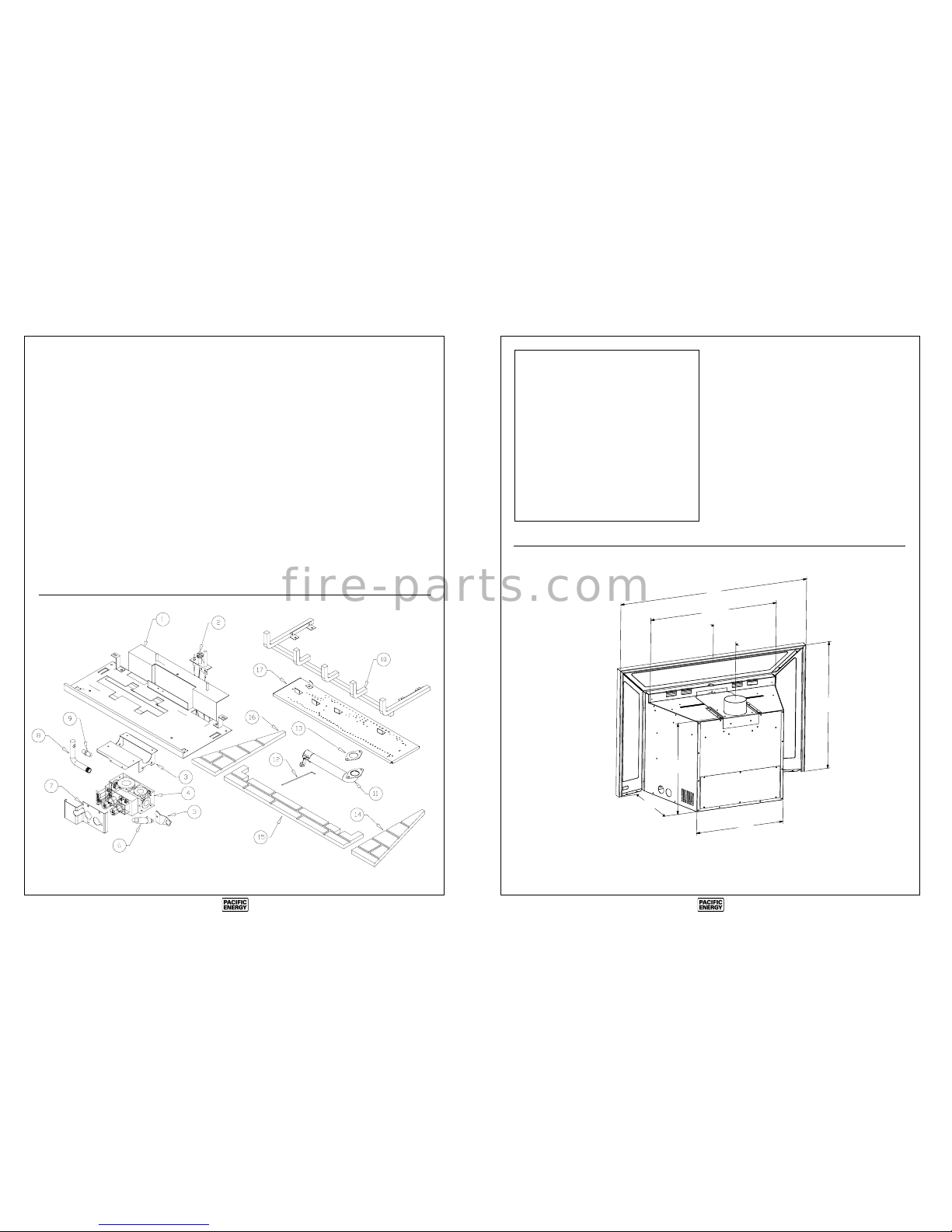
Standard-size Surround Assembly, Plain and Embossed Bevelled Panels ............. 37" wide x 25" high
Over-size Surround Assembly, Plain Flat Panels ................................................... 43" wide x 28" high
A B
Fig. # 1
A
10" to 14"
24 3/4"
B
17"
12 5/8"
17 7/8"
22
Burner Replacement Parts
See Fig. # 41
(WHEN ORDERING, INCLUDE PART NUMBER WITH DESCRIPTION)
ITEM DESCRIPTION PART NO. ITEM DESCRIPTION PART NO.
1 ...........Burner Plate Assembly ....................BRNA.2915
2 ...........Pilot Assembly, NG ..............................5009.157
.............Electrode Assembly c/w Wire ............ 5009.5001
.............Thermopile ................................................... 5010
.............Thermocouple ...........................................5010.3
.............Pilot Supply Tube c/w Fittings ........... 5003.0001
.............Pilot Orifice, NG ..................................... 5003.17
.............Pilot Orifice, LP .................................... 5009.169
3 ...........Valve Bracket ...............................................1983
4 ...........Gas Valve, NG ........................................ 5007.05
5 ...........Igniter Bracket ..............................................1984
6 ...........Igniter ........................................................ 5016.5
7 ...........Valve Cover ................................. MIND.186201
8 ...........Manifold .................................................. 5012.51
9 ...........Burner Orifice, NG (#45) .......................5021.34
.............Burner Orifice, LP (#55) ........................ 5021.35
10 .........Andiron Assembly ...................... BRNA.198531
11 .........Venturi Tube Assembly .............. BRNA.501131
12 .........Air Shutter Rod ............................................ 1752
13 .........Venturi Tube Gasket .................................... 5012
14 .........Brick Panel, Right ................................. 5094.245
15 .........Brick Panel, Front ................................. 5094.226
16 .........Brick Panel, Left ...................................5094.244
.............Brick Panel Set ....................................5094.2451
17 .........Burner Pan Assembly ...................... BRNA.1987
All parts may be ordered from your nearest Pacific Energy Gas Stove dealer. Contact Pacific Energy for the location of the dealer
nearest you.
Fig. # 41
f i r e - p a r t s . c o m
4
Safety
• Due to high temperatures, this gas appliance should be
located out of traffic and away from furniture and draperies.
• Children and adults should be alerted to the hazards
of high surface temperature and should stay away to
avoid burns or clothing ignition.
• Young children should be carefully supervised when
they are in the same room as the appliance.
• Clothing or other flammable material should not be
placed on or near the appliance.
• Any grill, panel or door removed for servicing the unit
must be replaced prior to operating. Failure to do so may
create a hazardous condition.
• Installation and repair should be done by a qualified
service person. The appliance should be inspected before
use and at least annually by a professional service person.
• More frequent cleaning may be required due to excessive lint from carpeting, bedding material, etc. It is imperative that control compartments, burners and circulating air passageways of the appliance be kept clean.
It is Pacific Energy’s policy that no responsibility is assumed
by the Company or by any of its employees or representatives
for any damages caused by an inoperable, inadequate, or
unsafe condition which is the result, either directly or indirectly, of any improper operation or installation procedures.
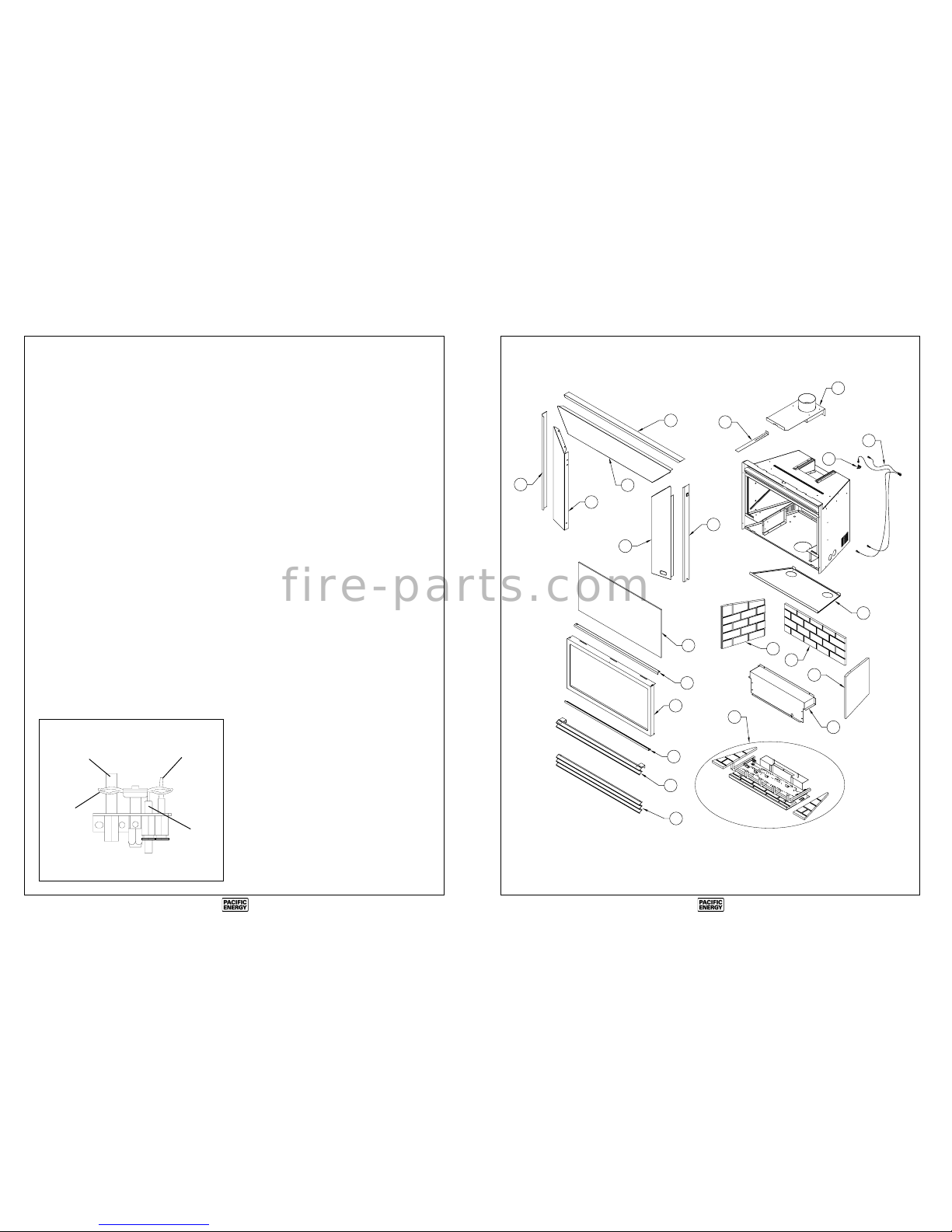
Fig. # 2
THERMOCOUPLE
THERMOPILE
PILOT
FLAME
ELECTRODE
Maintenance
Caution: Turn off gas and electrical power supply and allow
ample time for unit to cool before servicing appliance. It is
recommended that this appliance and venting should be
inspected at least once a year by a qualified service person.
Do not use this heater if any part has been under water.
Immediately call a qualified service technician to inspect the
heater and to replace any part of the control system and any
gas control which has been under water.
Glass Panel:
Warning: Do not operate appliance with glass panel re-
moved, cracked or broken. Replacement of the glass panel
should be done by a licensed or qualified service person.
Do not strike or otherwise impact the glass in anyway that
may cause it to break. If the glass becomes cracked or broken,
it must be replaced before using the fireplace. Replacement
glass can be obtained from your nearest Pacific Energy
dealer. The size required is 12 1/8" x 24 1/4" x 5mm. Use
ceramic glass only. Do not substitute with any other type.
To remove broken glass, fold down the front bottom louver
to access the window latches.
Disengage the over-center latches by pulling each lever down
and forward. Grasp the sides of the frame and swing the
bottom out to clear. Lift up and forward to disengage from the
top. Remove all particles of glass. Be careful as they are very
sharp. Install new glass complete with gasket. Replace frame.
Annual Inspection:
1) Clean louvers and air passage ways of excessive lint
buildup from carpeting, bedding material, etc. The flow of
combustion and ventilation air must not be obstructed.
2) Remove glass frame assembly and log set. Inspect logs
and burner assembly for lint and soot buildup. If excessive
buildup of soot is present, have a qualified service person
inspect and adjust unit for proper combustion. Clean logs and
burner with a vacuum cleaner, paying close attention to
burner ports.
3) Check the pilot system for proper operation (See Fig. #2).
4) Check that the chimney flue and its outlet are open and
free from blockage or debris.
5) Check glass panel gasket, replace if necessary.
Note: The appliance area must be kept clear and free from
combustible materials, gasoline and other flammable vapors
and liquids.
Periodically:
a) Viewing glass may be cleaned with glass cleaner.
b) Exterior porcelain enamel finish may be cleaned with soap
and water.
Note: Never use abrasives to clean this appliance.
21
Fig. # 40
3
1
4
5
9
7
6
8
2
19
19
17
18
16
19
15
10
13
14
11
13
12
f i r e - p a r t s . c o m
 Loading...