

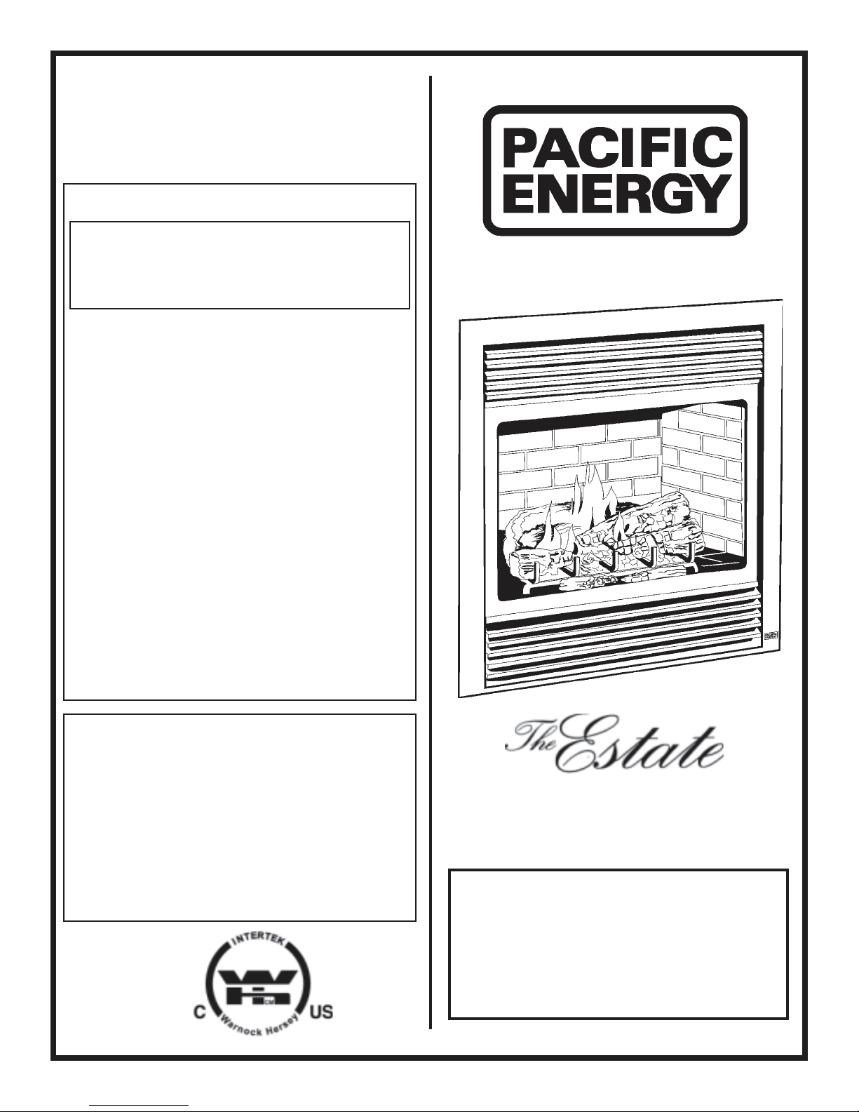
Pacific energy Estate Installation And Operating Instrictions
IMPORTANT:
THESE INSTRUCTIONS ARE TO
REMAIN WITH THE
HOMEOWNER
FOR YOUR SAFETY
WARNING: If the information in this manual
is not followed exactly, a fi re or explosion
may result causing property damage,
personal injury or loss of life.
-- Do not store or use gasoline or other
fl ammable vapors and liquids in the vicinity
of this or any other appliance.
-- WHAT TO DO IF YOU SMELL GAS
• Do not try to light any appliance.
• Do not touch any electrical switch; do
not use any phone in your building.
• Immediately call your gas supplier
from a neighbour’s phone. Follow
the gas supplier’s instructions.
• If you cannot reach your gas supplier,
call the fi re department.
--Installation and service must be performed
by a qualifi ed installer, service agency or
the gas supplier.
This appliance may be installed in an aftermarket permanently located, manufactured (mobile) home, where not prohibited
by local codes.
SERIES H
This appliance is only for use with the
type of gas indicated on the rating plate.
This appliance is not convertible for use
with other gases, unless a certifi ed kit is
DIRECT VENT FIREPLACE
INSTALLATION
AND OPERATING
INSTRUCTIONS
250505-36 ESTATE_H 5055.8.B
TOP VENT
OUTLET LOCATION
REAR VENT
OUTLET LOCATION
CONTENTS
CAUTION ..............................................................................................................3
INSTALLATION REQUIREMENTS .......................................................................4
CHASE INSULATION ...........................................................................................5
FRAMING WITHOUT SCREEN DOOR ................................................................6
FRAMING FOR SCREEN DOOR .........................................................................7
HEARTH EXTENSION ........................................................................................7
TOP OR REAR VENT ........................................................................................... 8
VENT ADAPTER INSTALLATION ........................................................................8
VENTING ...............................................................................................................9
ROOF TERMINATION VENTING AND VENT RESTRICTOR ............................ 10
VENT CONNECTION .......................................................................................... 11
VENT EXTENSION .............................................................................................12
VENT TERMINAL INSTALLATION ..................................................................... 13
ROOF VENT TERMINAL INSTALLATION ......................................................... 14
OPTIONAL VENTING ......................................................................................... 16
OPTIONAL SNORKEL VENT TERMINAL .........................................................19
MANUFACTURED (MOBILE) HOME .................................................................20
GAS SUPPLY ...................................................................................................... 20
WALL SWITCH OR THERMOSTAT ...................................................................20
BURNER REMOVAL ...........................................................................................21
OPTIONAL BRICK PANELS INSTALLATION ................................................... 21
LOG SET ASSEMBLY ........................................................................................22
OPTIONAL BLOWER ......................................................................................... 24
SCREEN DOOR INSTALLATION ....................................................................... 25
LIGHTING INSTRUCTIONS ..............................................................................26
FIRST FIRE ......................................................................................................... 27
OPERATION .......................................................................................................27
FLAME ADJUSTMENT .......................................................................................27
REPLACEMENT PARTS ....................................................................................28
BURNER REPLACEMENT PARTS ....................................................................29
APPENDIX A .......................................................................................................30
Louver Installation Guide ...........................................................................30
Wall Termination Kit ....................................................................................31
Roof Termination Kit ...................................................................................32
5' Vent Pipe Kit ............................................................................................ 33
10' Vent Pipe Kit .......................................................................................... 34
Safety Label .................................................................................................35
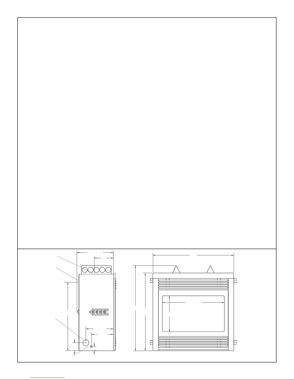
17 1/4"
9"
38"
GAS INLET
ACCESS HOLE
2 ESTATE_H 250505-36
31 1/2"
ELECTRICAL
ACCESS HOLE
3 3/4"
12 15/16"
10 3/8"
2"
40"
36 1/2"
29 1/8"
16 7/8"

CAUTION
MAINTENANCE
FOR YOUR SAFETY - Do not install or operate your Paci c Energy
Gas Stove without rst reading and understanding this manual. Any
installation or operational deviation from the following instructions voids
the Paci c Energy Gas Stove Warranty and may prove hazardous.
This appliance and its individual shutoff valve must be disconnected
from gas supply piping system during any pressure testing of that
system at test pressures in excess of 1/2 psig. (3.5 kPa)
This appliance must be isolated from the gas supply piping system
by closing its individual manual shutoff valve during any pressure
testing of the gas supply piping system at test pressures equal to or
less than 1/2 psig. (3.5 kPa)
Note: When lit for the rst time, the appliance will emit a slight odour
for a couple of hours. This is due to the curing of paints, sealants
and lubricants used in the manufacturing process. This condition is
temporary. Open doors and windows to ventilate area. Smoke and
fumes caused by the curing process may cause discomfort to some
individuals.
SAFETY
Due to high temperatures, this gas appliance should be located
out of traf c and away from furniture and draperies.
Children and adults should be alerted to the hazards of high
surface temperature and should stay away to avoid burns or
clothing ignition.
Young children should be carefully supervised when they
are in the same room as the appliance.
Clothing or other ammable material should not be placed
on or near the appliance.
Any grill, panel or door removed for servicing the unit must
be replaced prior to operating. Failure to do so may create a
hazardous condition.
Installation and repair should be done by a quali ed service
person. The appliance should be inspected before use and at
least annually by a professional service person. More frequent
cleaning may be required due to excessive lint from carpeting,
bedding material, etc. It is imperative that control compartments,
burners and circulating air passageways of the appliance be
kept clean.
It is Paci c Energy’s policy that no responsibility is assumed
by the Company or by any of its employees or representatives
for any damages caused by an inoperable, inadequate, or unsafe
condition which is the result, either directly or indirectly, of any
improper operation or installation procedures.
Caution: Turn off gas and electrical power supply and allow ample
time for unit to cool before servicing appliance. It is recommended
that this appliance and venting should be inspected at least once a
year by a quali ed service person.
Do not use this heater if any part has been under water. Immediately
call a quali ed service technician to inspect the heater and to replace
any part of the control system and any gas control which has been
under water.
Glass Panel:
Warning: Do not operate the appliance with the glass panel removed,
cracked or broken. Replacement of the glass panel should be done
by a licensed or quali ed service person. Do not strike or otherwise
impact the glass in anyway that may cause it to break. If the glass
becomes cracked or broken, it must be replaced before using the
replace. Replacement glass can be obtained from your nearest
Paci c Energy dealer. The size required is 31-1/4" x 19" x 5mm. Use
ceramic glass only. Do not substitute with any other type.
To remove broken glass, fold down the front bottom louver to access
the screw retaining the decorative window trim overlay if installed.
Remove the screw and swing the bottom out to clear. Lift to disengage from the top and remove. Place on a smooth surface to avoid
scratching.
Disengage the over-center latches by pulling each lever down and
forward. Grasp the sides of the frame and swing the bottom out to
clear. Lift up and forward to disengage from the top. Place the glass
frame assembly in a safe place to avoid damage. Remove all particles of glass. Be careful as they are very sharp. Install new glass
complete with gasket. Replace frame and screws.
Annual Inspection:
a) Clean louvers and air passage ways of excessive lint buildup from
carpeting, bedding material, etc. The ow of combustion and ventilation air must not be obstructed.
b) Remove glass panel and log set. Inspect logs and burner assembly for lint and soot buildup. If excessive buildup of soot is present,
have a quali ed service person inspect and adjust unit for proper
combustion. Clean logs and burner with a vacuum cleaner, paying
close attention to burner ports.
c) Ensure pilot is free of lint and dust. Check the pilot system for
proper ame size and operation. (See Fig. #1)
d) Check that the vent pipe and vent terminal are open and free from
blockage or debris. If the venting is disassembled for cleaning, it must
be properly assembled and resealed. Refer to VENTING section for
proper procedure.
e) Check glass panel gasket, replace if necessary. It is important
that the glass seal be maintained in good condition
Note: The appliance area must be kept clear and free from combustible
materials, gasoline and other ammable vapours and liquids.
Periodically:
a) Viewing glass may be cleaned with replace glass cleaner.
b) Exterior nish may be cleaned with soap and water.
Caution:
- do not use abrasive cleaners on glass or any other part of the
replace.
- do not clean glass when hot
Fig. # 1
250505-36 ESTATE_H 3
THERMOPILE
PILOT FLAME
THERMOCOUPLE
ELECTRODE
INSTALLATION REQUIREMENTS
The Estate Fireplace installation and venting must conform
to the current CAN/CGA-B149 installation code (in Canada) or
the National Fuel Gas Code, ANSI Z223.1 -1988 (in the USA), and
approved per local codes. Only quali ed (licensed or trained)
personnel should install this product.
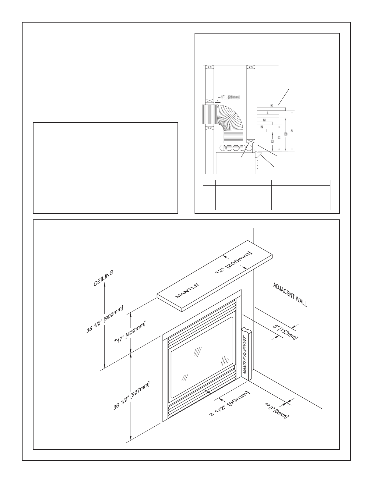
Fig. # 3
MANTEL CLEARANCES
WITH MANTEL SHIELD
The Estate Fireplace is designed to be framed at zero clearance
to combustible material with conventional lumber. Ensure framing
dimensions are maintained during construction.
NOTE: If a screen front is installed, cement board will be required on
the front face, see required clearances on the following page, and the
Screen Front Framing Section.
Minimum Clearances to Combustibles:
Side standoffs .......................................0 in. (0 mm)
Back standoffs ......................................0 in. (0 mm)
Top standoffs ........................................0 in. (0 mm)
Adjacent sidewall: .................................6 in. (152 mm)
Ceiling to appliance: .....................35 1/2 in. (902 mm)
Mantel to appliance: ...........................17 in. (432 mm)
Maximum mantel extension: ...............12 in. (305 mm)
With Mantel Shield ..........................See Figure # 3
Mantel support (3 1/2" wide max.) ........0 in. (0 mm)
Pacifi c Energy Vent pipe ......................1 in. (25 mm)
Simpson Dura-Vent GS pipe ......... 1-3/4 in. (45 mm)
Fig. # 2
Clearance without
*
mantel shield
COMBUSTIBLE MANTEL
HEADER
Ref. Mantel Width Ref. Clearance
K 12" (305 mm) A 17" (432 mm)
L 9 1/4" (235 mm) B 14" (356 mm)
M 6 5/8" (168 mm) C 11" (279 mm)
N 4" (102 mm) D 8" (203 mm)
FINISHED WALL
MANTEL SHIELD
**Allow 1/2" for
Screen Door Installations
4 ESTATE_H 250505-36
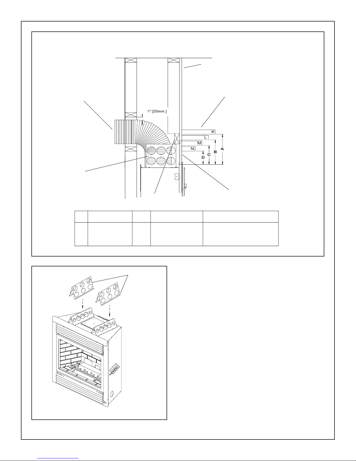
Fig. # 3a
MANTEL CLEARANCES
WITH OPTIONAL SCREEN FRONT
FINISHED WALL
TOP OR
REAR
VENTING
TOP
EXTENDED
STANDOFF
HEADER
Ref. Mantel Width Ref. Clearance Clearance
Top Edge of Screen Top Edge of Unit
K 12" (305 mm) A 16 1/4" (413 mm) 17 (432 mm)
L 9 1/4" (235 mm) B 13 1/4" (337 mm) 14" (356 mm)
M 6 5/8" (168 mm) C 10 1/4" (260 mm) 11 " (280 mm)
N 4" (102 mm) D 7 1/4" (184 mm) 8" (203 mm)
COMBUSTIBLE
MANTEL
8" HIGH
CEMENT BOARD
MANDATORY WITH
SCREEN DOORS
Fig. # 3b
Top
Extended
Standoffs
OPTIONAL SCREEN DOOR
TOP STANDOFFS
The Estate Fireplace is shipped with the short top standoffs in place
and the extended top standoffs loose. If the Optional Screen Door
is to be installed, the short standoffs must be replaced with the
extended standoffs.
1) Remove the four screws attaching each top standoff in place
and remove the standoffs.
2) Position extended top standoffs in the same place and attach
with the four screws.
CHASE INSULATION
When installing this replace against a non-insulated exterior wall
or chase, it is recommended that the outer walls be insulated to
same degree as other exterior walls. Do not place the replace
directly against the insulation. Cover the insulation and plastic
vapour barrier with a solid surface, such as drywall (sheetrock).
Consult local codes.
250505-36 ESTATE_H 5
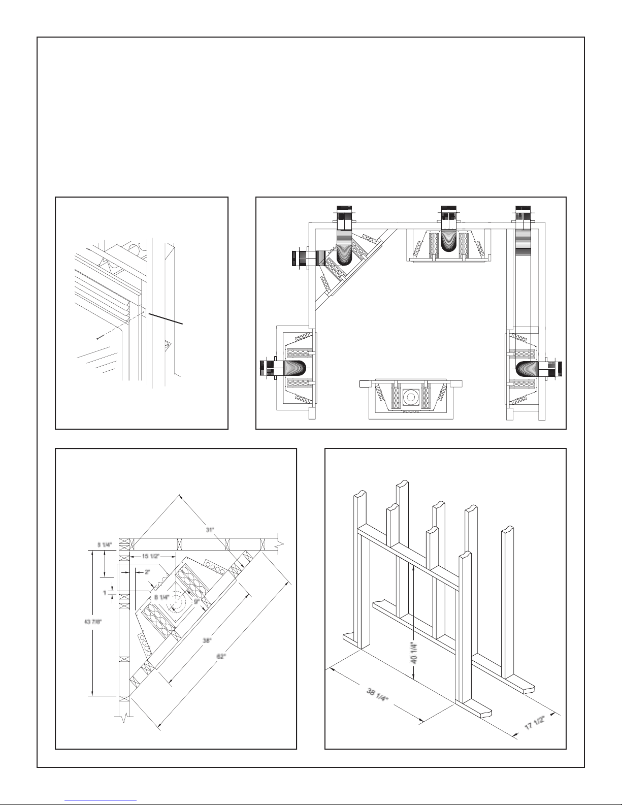
FRAMING WITHOUT SCREEN DOOR
In planning the installation for the Estate Fireplace, it is necessary to
determine where the unit is to be installed, location of vent system
and where gas supply piping may be plumbed. It may be installed
into an existing wall, a corner, a built-in wall or a wall projection. (see
Fig. # 5) Due to high temperatures, do not locate this appliance in
areas of high traf c or near furniture or draperies.
Once the nal location has been determined, frame a minimum
opening of 38-1/4 inches wide, 40-1/4 inches high and 17-1/2 inches
deep with conventional 2 x 4 lumber. (see Fig. # 6 and # 7) It may
be preferred to frame the replace after it is positioned and the vent
system is installed. Heavier construction may be required for some
Fig. # 4
NAILING
TAB S
Fig. # 5
installations, consult local building codes for speci c requirements.
Ensure framing dimensions are maintained during construction.
Bend out the two nailing tabs on each side and secure the replace
to framing with screws or nails. (see Fig. # 4) The tabs will allow
for a 3/4 inch thick nishing wall. The wall may be nished up to the
replace facing with combustible material. (see Fig. # 3)
The minimum clearances from the appliance to combustible surfaces
are shown on Fig. # 2 and # 3. Adequate clearances around air openings and combustion air supplies are required. If installing a screen
front, see required clearances in that section.
Examples of
Common Installation
Locations
Fig. # 6
CORNER FRAMING
DIMENSIONS
Fig. # 7
FRAMING DIMENSIONS
6 ESTATE_H 250505-36
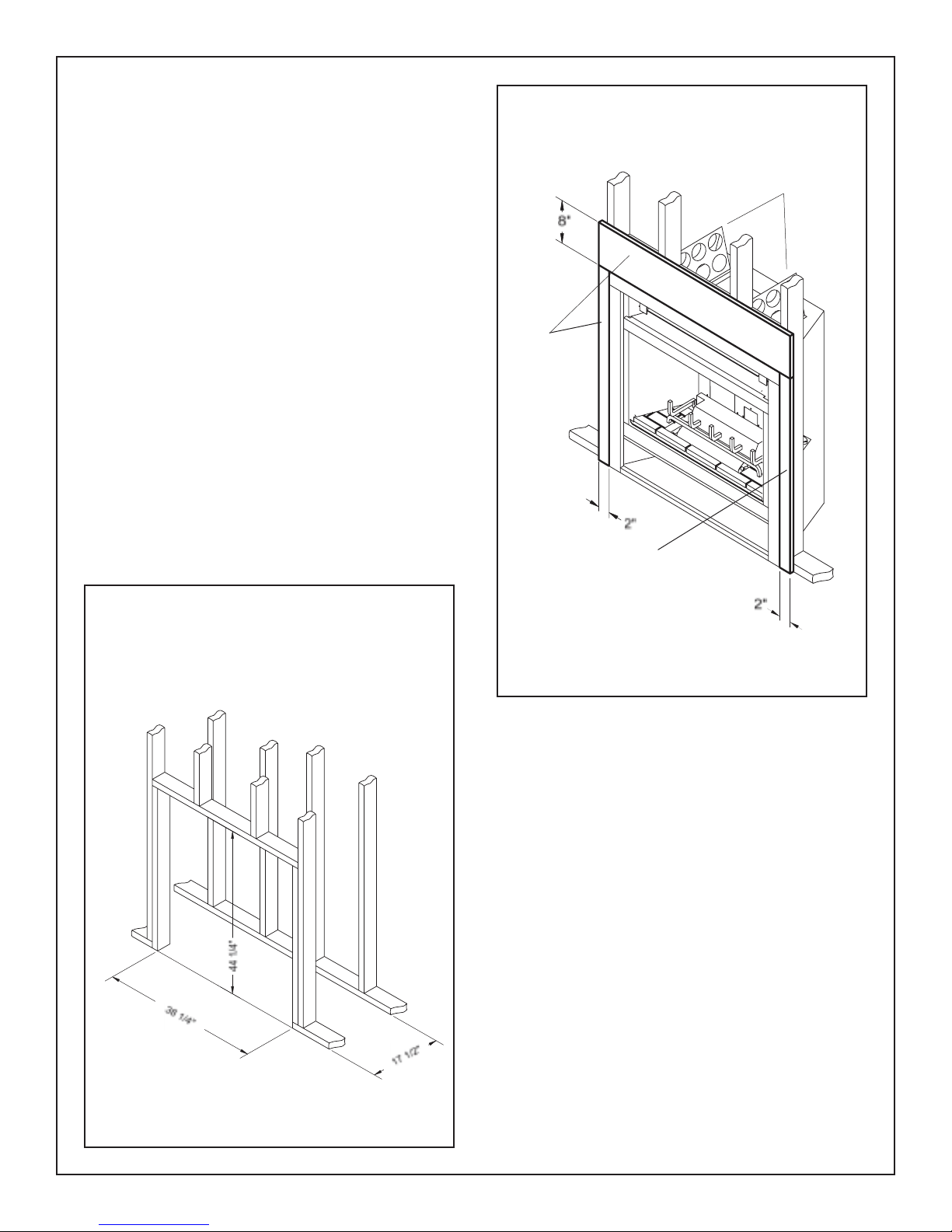
FRAMING FOR SCREEN DOOR
In planning the installation for the Estate Fireplace, it is necessary to
determine where the unit is to be installed, and where the location of
vent system and gas supply piping may be plumbed. Various installations are possible, such as, into an existing wall, a corner, a built-in
wall or a wall projection (see Fig. #5). Due to high temperatures, do
not locate this replace in areas of high traf c or near furniture or
draperies.
Once the nal location has been determined, frame a minimum
opening of 38-1/4 inches wide, 44-1/4 inches high and 17-1/2 inches
deep with conventional 2 x 4 lumber (see Fig. #6 & 7a). It may be
preferred to frame the replace after it is positioned and the vent
system is installed. Heavier construction may be required for some
installations, consult local building codes for speci c requirements.
Ensure framing dimensions are maintained during construction.
Bend out the two nailing tabs on each side and secure the replace
to framing with screws or nails (see Fig. #4). The tabs will allow for
a nishing wall up to 3/4 inch thick, if thicker, unit must be spaced
outwards accordingly.
Due to higher temperatures with the Screen Door, concrete board (or
other non-combustible material) must be used to sheet in the front of
the replace. The concrete board must extend 8" above and 2" down
the side of the unit. See gure #7b. Standard sheetrock (drywall) may
be used beyond this and up to the sides of the replace.
Fig. #7b
Concrete
Board
CONCRETE BOARD DETAIL
Extended
Top Standoffs
Fig. # 7a
FRAMING DIMENSIONS
OPTIONAL SCREEN DOOR
Concrete
Board
Concrete board (or other non-combustible material)
must extend 8" above and 2" down the side of the unit.
The minimum clearances from the appliance to combustible surfaces
are shown on Fig. # 2 & 3a. Adequate clearances around air openings
and combustion air supplies are required.
Refer to the replace installation manual supplied with the unit for
additional requirements.
HEARTH EXTENSION
The Estate replace is designed to be installed on a combustible
oor. A noncombustible hearth extension is not required for this
model. If one is desired, the hearth extension must be ush to the
bottom of the replace.
250505-36 ESTATE_H 7
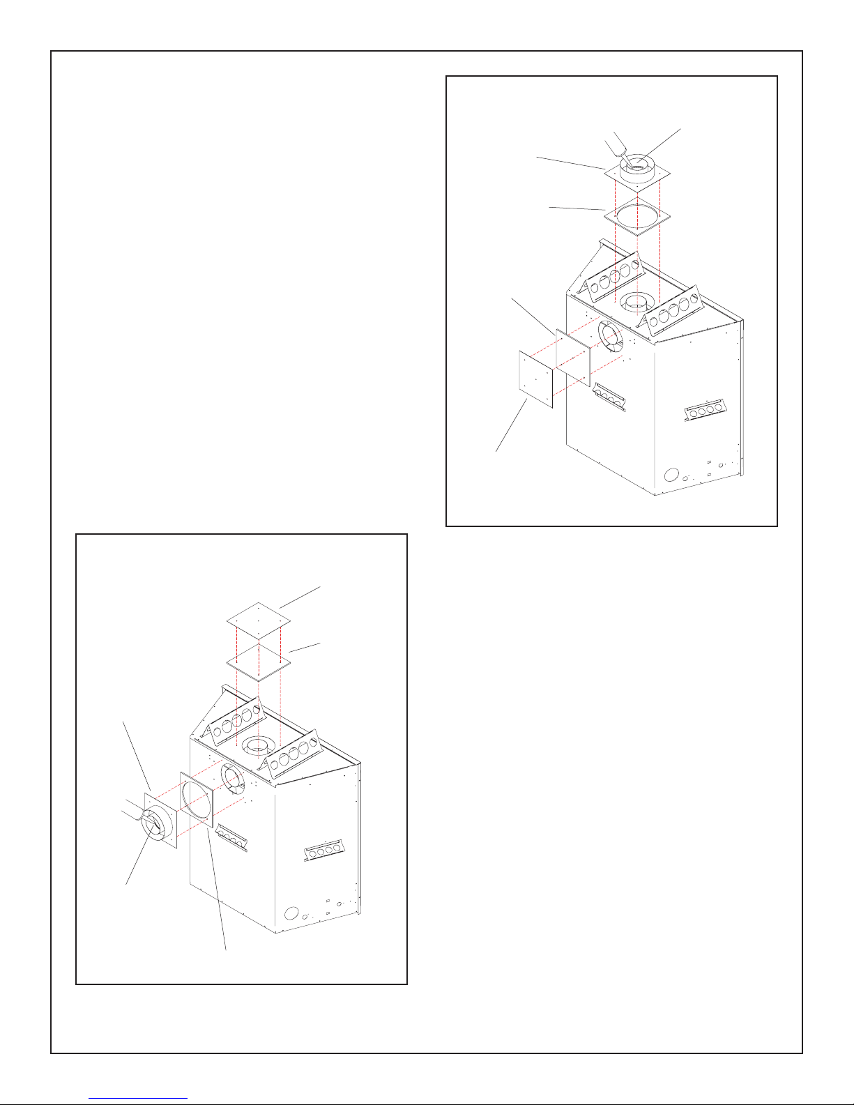
TOP OR REAR VENT
Caution: The vent outlet not being used for venting must be blocked
with the vent cover plate and gasket.
The Estate is capable of top or rear vent applications. The replace
is factory set for top vent application (see Fig. #8a).
If you choose to use this appliance in a rear vent application you
must re- install the vent cover plate and gasket on the top vent outlet
(see Fig. #8b).
Vent cover plate removal and installation.
Fig. # 8a
Black Sealant
Vent Adapter
Adapter Gasket
1) Remove the ve # 8 x 1/2" sheet metal screws that attach the
vent cover plate to the rear of the appliance. Remove the cover
plate and gasket. Be careful not to damage the gasket.
2) Remove the four screws around the top vent outlet.
3) Place the gasket and vent cover plate over the top vent outlet.
4) Secure in place with screws previously removed (see Fig.
#8b).
Fig. # 8b
Vent Cover
Plate
Vent Cover
Gasket
Vent Cover
Gasket
Vent Cover
Plate
VENT ADAPTER INSTALLATION
The Estate replace easily adapts to use either the Paci c Energy Flex
Vent, or the Simpson Dura-Vent GS venting system. Each system
requires a speci c vent adapter. Use the Paci c Flex Vent adapter
(ENCD.PEADPT) or the Dura-Vent adapter (ENCD.DVADPT).
Vent Adapter
Black Sealant
Adapter Gasket
8 ESTATE_H 250505-36
Supplied with each adapter is a ceramic gasket (# 5068.2761) that
must be used.
Installation:
The adapter 4" pipe must be sealed to the replace 4" vent outlet. Failure
to seal this joint may cause the replace to not operate properly.
1) Apply a bead of black sealant (supplied with the replace) to the
inside of the ared end of adapter (See Figs. #8a &8b).
2) Place the gasket and vent adapter over the vent outlet and align
with attachment holes.
3) Secure in place with the four #8 x 1/2” sheet metal screws previously removed.
VENTING
Before installing venting for this unit, the installer should read these
instructions to ensure that the proper vent con guration has been
selected.
Use only Paci c Energy vent kits #:
GASC.WALKIT - Wall Termination Kit
ESTD.ROTKIT - Roof Termination Kit
ESTD.VP05 - 5' Vent Pipe Kit
ESTD.VP10 - 10' Vent Pipe Kit
Standard roof ashing or ashing listed below may be used.
ESTD.ROFLAT - Flat Roof Flashing ( at roof)
ESTD.ROADJ - Adjustable Roof Flashing (1/12 to 7/12 pitch)
ESTD.ROSTP - Steep Roof Flashing (8/12 to 12/12 pitch)
Vent system components approved for use with the Estate Fireplace
are shown in Figure # 9 and Appendix A. The Estate Fireplace is
also tested and certi ed for use with SIMPSON DURA-VENT DIRECT
VENT GS pipe (see Optional Venting section).
NO OTHER VENTING SYSTEMS OR COMPONENTS MAY BE
USED.
Various combinations of vertical and horizontal runs may be used.
Refer to Figures # 8c, 8d, & 8f for details. For optimum performance
and ame appearance, keep the vent length to a minimum. Connections between each vent system component must be tightly joined
and sealed, and secured with sheet metal screws at each joint. A
horizontal run of vent must have a 1/4" rise for every 2 ft.of run towards the termination.
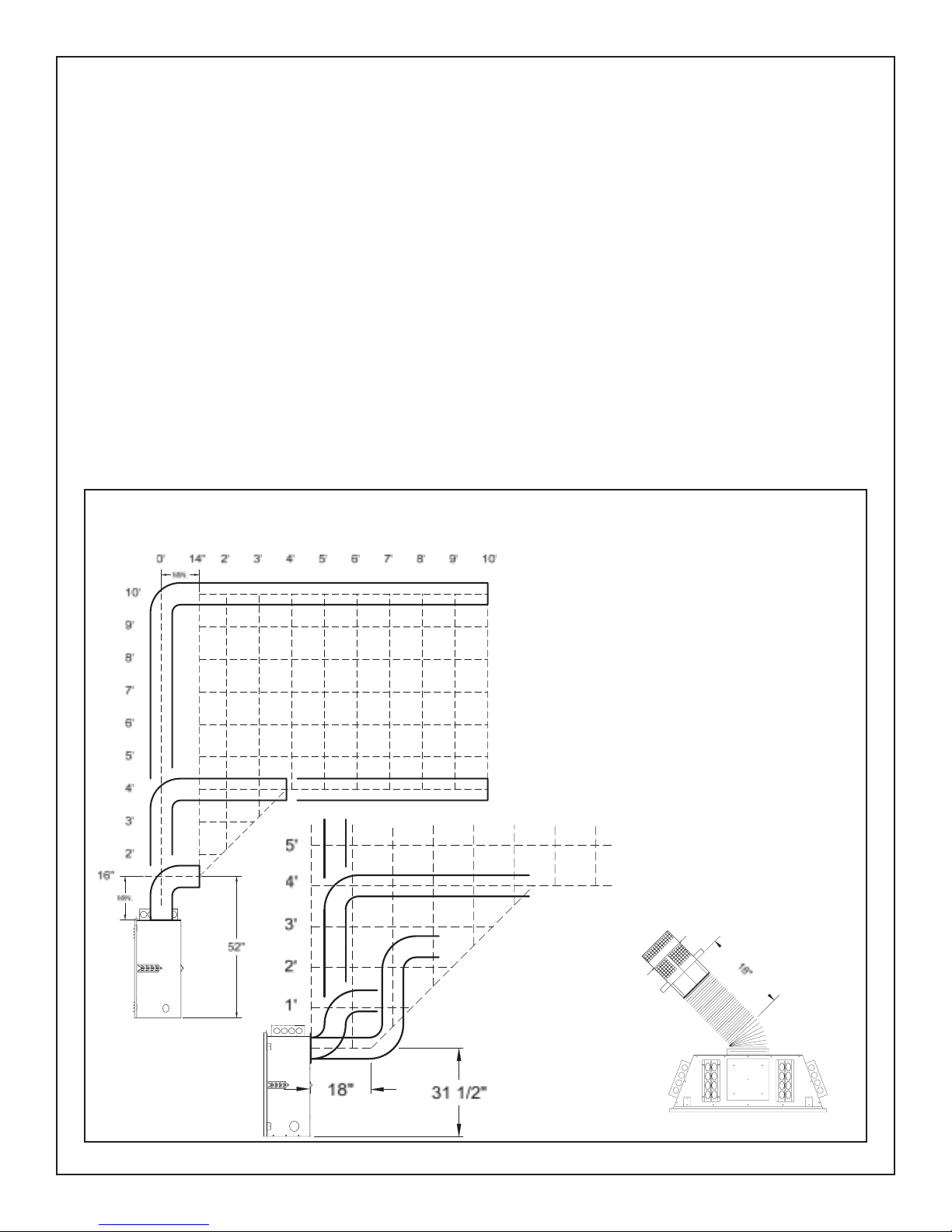
Fig. # 8c
PACIFIC ENERGY
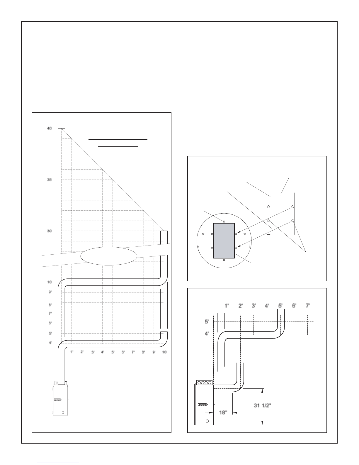
WALL TERMINATION VENTING
HORIZONTAL RUN
CAUTION: UNDER NO CONDITION SHOULD COMBUSTIBLE
MATERIAL BE CLOSER THAN 1 INCH FROM THE VERTICAL
AND HORIZONTAL SECTIONS OF THE PACIFIC ENERGY VENT
SYSTEM OR 1-3/4 INCHES FROM THE SIMPSON DURA-VENT
DIRECT VENT GS SYSTEM.
Exterior wall opening:
IMPORTANT: Before cutting an opening in an exterior wall, ensure
correct vent terminal location by referring to the clearance speci cations noted on Figure #13.
It is preferred to cut an opening between two building framing members to avoid any extra framing. Consult your local building codes
prior to proceeding. The vent kit will accommodate a maximum wall
thickness of 11-1/2 inches.
Having determined the vent terminal location, cut and frame an opening of 10-1/2 inches. The opening may be round or square. Minimum
distance from the nished oor to the centre of the opening in a at
wall is 52 inches, and 59-1/4 inches in a corner installation for top
vent, or 31-1/2" for rear vent. Height of the opening will vary with
each installation. As the horizontal vent run increases, so does the
minimum vertical rise.
NOTE: The vent must not exceed
a total length of 20 feet. Any combination of rise and run may be
used but must be constrained to
the boundaries of this chart. For
each additional 90° elbow, reduce
vent length by 2 feet. For each
additional 45° elbow, reduce vent
length by 1 foot.
VERTICAL RISE
NOTE: The minimum top exit vent
length is a combination of 16" rise
and 14" run. For longer venting
confi gurations, the rise and run
must be constrained to the boundaries of this chart.
1' 2' 3' 4' 5' 6' 7'
NOTE: At 31 1/2" up, the maximum horizontal rear exit vent
length is 18" with a 45° elbow
(see below).
250505-36 ESTATE_H 9
PACIFIC ENERGY
ROOF TERMINATION VENTING AND VENT RESTRICTOR
NOTE:
The vent must be a minimum 4' long and must not exceed
a total length of 40'. Any combination of rise and run may be used
but must be constrained to the boundaries of the charts shown in
Figs. #8d & 8f.
Fig. # 8d
ROOF TERMINATION
TOP VENTING
Included with the unit is a Vent Restrictor. This item is used for air
ow regulation when the vent height is 25 ft. or more. Installation of
this restrictor ensures proper ame appearance for the wide variety of
vent con gurations. If the ames are bent forward and have excessive
movement, the vent restrictor is required.
Refer to the Burner Removal section for installation location of the
restrictor (see Fig. #21). Remove the glass front, and the two rear
logs. Remove the one top mounting screw shown in Fig. #8e, place
the restrictor over the hole, and replace the one screw.
Fig. # 8e
MOUNTING SCREW
HOLE
RESTRICTOR AIR
OPENING
MOUNTING SCREW
VENT RESTRICTOR
VERTICAL RISE
Vent Restrictor
required above
25 ft.
HORIZONTAL RUN
NOTE: The vent must not exceed a
total length of 40 feet. Any combination
of rise and run may be used but must
be constrained to the boundaries of this
chart. For each additional 90° elbow,
reduce horizontal vent length by 2 feet.
For each additional 45° elbow, reduce
horizontal vent length by 1 foot.
Fig. # 8f
VERTICAL RISE
AIR INLET OPENING
AT FIREBOX BACK.
PLACE RESTRICTOR
DIRECTLY OVER
THIS OPENING
HORIZONTAL RUN
ROOF TERMINATION
REAR VENTING
SCREW
CLEARANCE
HOLES
NOTE: The vent
must have a minimum of 4' rise
10 ESTATE_H 250505-36
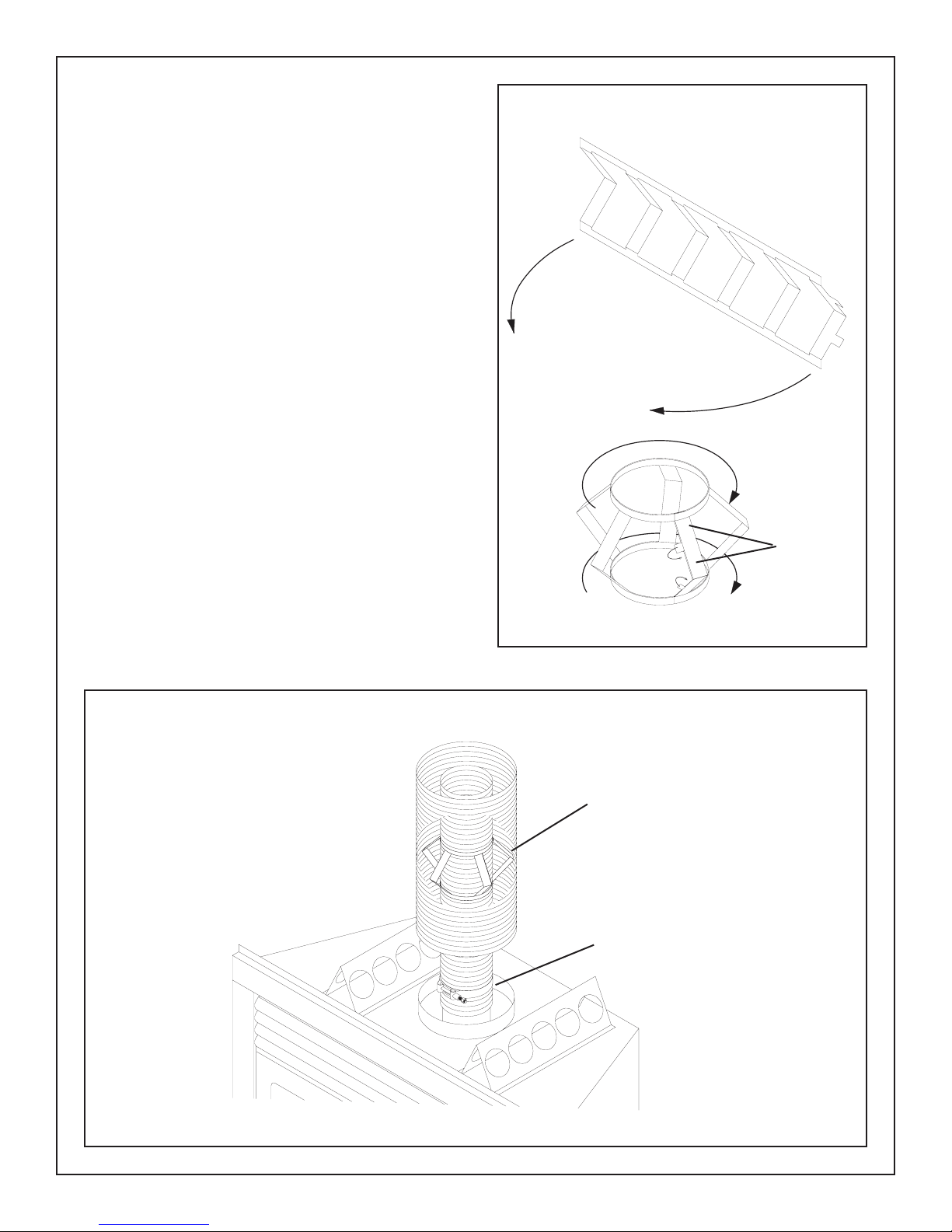
VENT CONNECTION
Note: This section refers only to Paci c Energy ex vent.
Attaching the venting to the unit before framing begins is preferred.
Once the replace is in position proceed to attach the venting. (see
Fig # 9)
The exible vent pipe may be stretched to accommodate various
lengths of venting. Stretch and/or cut to length as required.
The 4 inch exible inner pipe must be centred inside the 8 inch pipe
with pipe spacers provided. Pipe spacers should be installed at
maximum 2 foot intervals. (see Fig. # 10) Spacers may have to be
closer if pipe is bent 90°.
1) Bend pipe spacer around the 4 inch inner pipe. With ends of
spacer overlapped, bend locking tabs into place. (see Fig. # 10)
2) Slip the 4 1/2 inch pipe clamp loosely over the inner ex pipe.
Slide the pipe a minimum 1 1/2 inches over the inner sleeve collar of
the appliance. Clamp tightly in place (see Fig. # 9). No additional
seal is required. Secure in place with screws provided.
3) Slip the 8 inch outer ex pipe onto the larger collar and secure
in place with screws provided. Seal the joint with high temperature
sealant provided.
Fig. # 10
BEND TABS
OVER
Fig. # 9
PIPE SPACER
PIPE CLAMP
250505-36 ESTATE_H 11
 Loading...