

Pacific energy BROADWAY GBWY.BODYA, BRENTWOOD GBNT.BODYA Installation And Operating Instructions Manual
INSTALLER:
Leave this manual with the appliance.
CONSUMER:
Retain this manual for future reference.
WARNING: If the information in these
instructions is not followed exactly a fire or
explosion may result causing property
damage, personal injury or death.
FOR YOUR SAFETY
Do not store or use gasoline or other
flammable vapours and liquids in the vicinity
of this or any other appliance.
WHAT TO DO IF YOU SMELL GAS
Do not try to light any appliance.
Do not touch any electrical Switch.
Do not use any phone in your building.
Immediately call your gas supplier
from a neighbour’s phone. Follow the
gas supplier’s instructions.
If you cannot reach your gas supplier
call the fire department.
Installation and service must be performed
by a qualified installer, service agency or the
gas supplier.
This appliance may be installed in an
aftermarket permanently located,
manufactured home (USA only) or mobile
home, where not prohibited by local codes.
This appliance is only for use with the type of
gas indicated on the rating plate. This
appliance is not convertible for use with
other gases unless a certified kit is used.
This appliance is suitable for installation in a
bedroom or bed sitting room.
BROADWAY & BRENTWOOD
INSTALLATION AND
OPERATING INSTRUCTIONS
MODEL:
BROADWAY GBWY.BODYA
&
BRENTWOOD GBNT.BODYA
FIREPLACE INSERT
080913 GBWY.BODYA / GBNT.BODYA 5055.66

Section 1
Table Of Contents
Caution.................................................................3
Safety...................................................................4
Owners Information
First Fire...............................................................5
Remote control.....................................................6
Maintenance......................................................12
Lighting Instructions...........................................13
Installer information
Commonwealth of Massachusetts.....................14
Fireplace Dimensions........................................15
Existing Fireplace Preparation...........................16
Clearances to Combustibles..............................17
Venting...............................................................18
Plumbing and Electrical.....................................19
Gas Supply........................................................20
Gas Pressure Check / Output / Efficiency.........20
Gas Pressure Testing Procedure.......................21
Pilot Adjustment.................................................21
Propane Conversion..........................................22
Door Installation / Removal................................23
Fan Installation/ Removal..................................23
Panel Installation/Removal................................24
Log Burner Kit Installation/Removal..................25
Log Set Installation/Removal.............................26
Glass Burner Kit Installation/Removal...............27
Replacement Parts / Kits List............................23
Wiring Diagram..................................................29
Notes..................................................................30
2
Section 1
FOR YOUR SAFETY
- Do not install or operate your Pacific Energy appliance without first
reading and understanding this manual. Any installation or operational deviation from the
following instructions voids the Pacific Energy Warranty and may prove hazardous.
This appliance and its individual shut off valve must be disconnected from gas supply piping
system during any pressure testing of that system at test pressures in excess of 1/2 psig
(3.5 kPa).
This appliance must be isolated from the gas supply piping system by closing its individual
manual shut off valve during any pressure testing of the gas supply piping system at test
pressures equal to or less than 1/2 psig (3.5 kPa).
Note: When lit for the first time, the appliance will emit a slight odor for a couple of hours. This is
due to the curing of paints, sealants and lubricants used in the manufacturing process. This
condition is temporary. Open doors and windows to ventilate area. Smoke and fumes caused by
the curing process may cause discomfort to some individuals.
Do not use the fireplace if any part has been under water. Immediately call a qualified service
technician to inspect the fireplace and to replace any part of the control system and any gas
control which has been under water.
This unit must be installed with a Burner Set, Panel Set, and Surround Kit component.
Caution
3

Section 1
Due to high temperatures, this gas appliance should be located out of traffic and away
from furniture and draperies.
Children and adults should be alerted to the hazards of high surface temperatures and
should stay away to avoid burns or clothing ignition.
Young children should be carefully supervised when they are in the same room as the
appliance. Toddlers, young children and others may be susceptible to accidental contact
burns. A physical barrier is recommended if there are at risk individuals in the house. To
restrict access to a fireplace or stove, install an adjustable safety gate to keep toddlers,
young children and other at risk individuals out of the room and away from hot surfaces.
Clothing or other flammable material should not be placed on or near the appliance.
A barrier designed to reduce the risk of burns from the hot viewing glass is provided with
the Surround Kit component and shall be installed.
If the barrier becomes damaged, the barrier shall be replaced with the manufacturers
barrier for this appliance.
Any grill, panel or door removed for servicing the unit must be replaced prior to operating.
Installation and repair should be done by a qualified service person. The appliance should
be inspected before use and at least annually by a professional service person. More
frequent cleaning may be required due to excessive lint from carpeting, bedding material,
etc. It is imperative that control compartments, burners and circulating air passageways of
the appliance be kept clean.
This appliance must not be connected to a chimney flue serving a separate solid fuel
burning appliance.
It is our policy that no responsibility is assumed by the Company or by any of its
employees or representatives for any damages caused by an inoperable, inadequate, or
unsafe condition which is the result, either directly or indirectly, of any improper operation
or installation procedures.
Safety
4

OWNER’S
INFORMATION
Section 2
Congratulations on your purchase of a Pacific Energy Gas Appliance.
Your fireplace has been professionally installed by:
Dealer name: ___________________
Phone Number:_________________
If you discover any problems with your gas appliance contact your dealer immediately to have the
unit repaired.
Caution: Do not attempt to repair the fireplace because you may cause injury to yourself or others,
and risk causing damage to the unit.
Before operating your appliance carefully read this manual and pay close attention to all Safety
Warnings. The manual contains important information on the unit’s safe operation and
maintenance.
When lit for the first time, the fireplace will emit a slight odor for a couple of hours. This is due to
the curing of paints, sealants and lubricants used in the manufacturing process. This condition is
temporary. Open doors and windows to ventilate area. Odor caused by the curing process may
cause discomfort to some individuals.
It is normal for fireplaces fabricated of steel to give off some expansion and/or contraction noises
during the start up or cool down cycle. Similar noises are found with your furnace heat exchanger
or cook stove oven.
First Fire
5
OWNER’S
INFORMATION
Section 2
Remote Control Operation
System Description
The Proflame Remote Control System consists of two elements:
1. Proflame Transmitter.
2. Proflame Integrated Fireplace Control (IFC) board and a wiring harness to connect the IFC
to the gas valve and stepper motor.
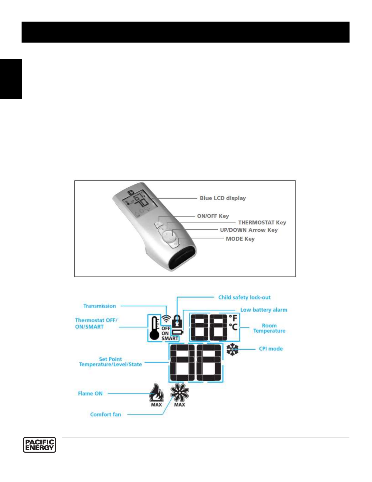
Transmitter (Remote Control with LCD Display)
The Proflame Transmitter uses a streamline design with a simple button layout and informative
LCD display (Fig. 1). The transmitter is powered by 3 AAA type batteries. A Mode key is provided
to Index between the features and a Thermostat key is used to turn on/off or index through
thermostat functions (Fig. 1 & 2).
Figure 1: Proflame Transmitter
Figure 2: Transmitter LCD display
`
6

OWNER’S
INFORMATION
Section 2
OPERATING PROCEDURE
Initializing the System for the first time
Install the 4 AA batteries into the battery box. Note the polarity of the battery and insert into the
battery box as indicated on the Battery cover (+/-). Set the main ON/OFF and the CPI/IPI switch in
the closed position. Press the program button on the IFC module. The IFC will “beep” three (3)
times to indicate that it is ready to synchronize with a Transmitter. Install the 3 AAA type batteries in
the battery bay, located on the base of the Transmitter. With the batteries installed in the
Transmitter, push the ON button. The Receiver will “beep” four times to indicate the Transmitter’s
command is accepted. If a second Transmitter must be registered it can be turned ON. The
receiver will beep again four (4) times and exit the synchronization phase. If only one transmitter is
used, then press again the button program to exit the synchronization phase.
The system is now initialized.
IFC Module
The Proflame 2 Integrated Fireplace Control (IFC) board is a device that allows the automatic
ignition and pilot flame supervision, to command the functions of a hearth appliance. It is
configured to control the ON/OFF main burner operation, giving the choice of both IPI (intermittent
pilot ignition), and CPI (continuous pilot ignition) modes.
The Proflame 2 IFC board controls and connects directly to the pilot assembly and an automatic
valve of the Proflame 880, 886 and 885 families using low electric power.
The IFC Board can be powered by an AC and battery pack for back up (ATMO Systems only). The
Proflame 2 offers the added ability to control the comfort fan speed from OFF through six (6)
speeds, a remotely actuated auxiliary outlet and a dimmable light outlet. The external batteries can
provide DC power to the IFC allowing the batteries to be used only when line power is interrupted
or lost.
7
OWNER’S
INFORMATION
Section 2
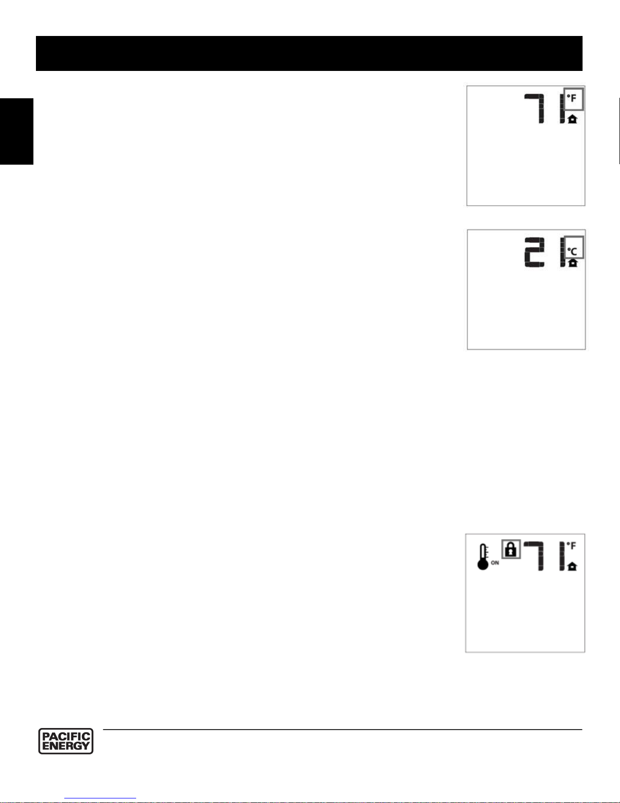
Temperature indication Display
With the system in the “OFF” position, press the Thermostat Key and the
Mode Key at the same time. Look at the LCD screen on the transmitter to
verify that a C or F is visible to the right of the Room Temperature display.
(Fig. 3 & 4)
Turn on the Appliance
First close the main ON/OFF switch on the wirings. With the system OFF,
press the ON/OFF Key on the Transmitter. The Transmitter display will show
all active Icons on the screen. At the same time IFC will be commanded to
start the ignition process. Once the pilot flame is proven the IFC board will
open the main valve outlet and the appliance main burner will also ignite. A
single “beep” from the IFC module will confirm reception of the command.
Turn off the Appliance
With the system ON, press the ON/OFF Key on the Transmitter. The
Transmitter LCD display will only show the room temperature. At the same
time the IFC will be commanded to turn off the burner. Depending on the
system mode (IPI or CPI) the pilot may shut off (IPI) or remain lit (CPI) and
the appliance burner turns OFF. A single “beep” from the Receiver confirms
reception of the command.
Manual Bypass of the Remote System
If the batteries of the receiver or transmitter are low or depleted, the
appliance can be turned off manually using switch located on battery box.
This will bypass the remote control feature of the system.
Key Lock
This function will lock the keys to avoid unsupervised operation.
To activate this function, press the MODE and UP keys at the same time
(fig.5).
To de-activate this function, press the MODE and UP keys at the same time.
Figure 3: Display in Fahrenheit
Figure 4: Display in Celsius
Figure 5
8
OWNER’S
INFORMATION
Section 2
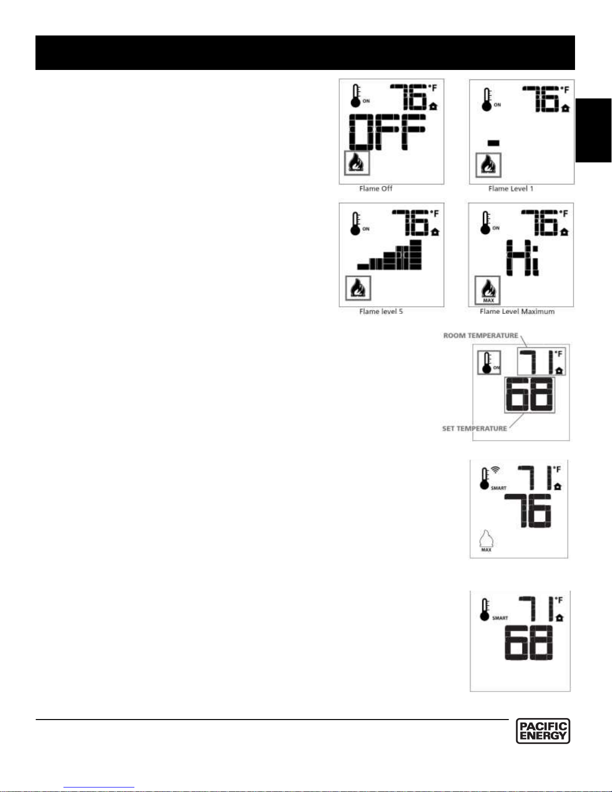
Remote Flame Control
The Proflame has six (6) flame levels. With the
system on, and the flame level at the maximum in
the appliance, pressing the down arrow key once
will reduce the flame height by one step until the
flame is turned off.
The Up Arrow Key will increase the flame height
each time it is pressed. If the Up Arrow Key is
pressed while the system is on but the flame is off,
the flame will come on in the high position. (Fig. 6)
A single “beep” will confirm reception of the
command.
ROOM THERMOSTAT (Transmitter Operation)
The Remote Control can operate as a room thermostat. The
thermostat can be set to a desired temperature to control the
comfort level in a room.
To activate this function, press the Thermostat key (Fig. 1). The
LCD display on the transmitter will change to show that the room
thermostat is “ON” and the set temperature is now displayed
(Fig.7). To adjust the set point, press the up or down arrow keys
until the desired set point temperature is displayed on the LCD
screen of the transmitter.
Smart Thermostat (Transmitter Operation)
The Smart Thermostat function adjusts the flame height in
accordance to the difference between the set point and the room
temperatures. As the room temperature gets closer to the set point
the Smart Function will modulate the flame down. If the room
temperature is cool the Smart function will modulate the flame up.
To activate this function, press the THERMOSTAT key (Fig. 1)
until the word "SMART" appears to the right of the temperature
bulb graphic (Fig. 8). To adjust the set point, press the up or down
arrow keys until the desired set point temperature is displayed on
the LCD screen of the transmitter (Fig. 9).
Figure 6:
Figure 7
Figure 8: Smart Flam
Function
Figure 9
9
OWNER’S
INFORMATION
Section 2
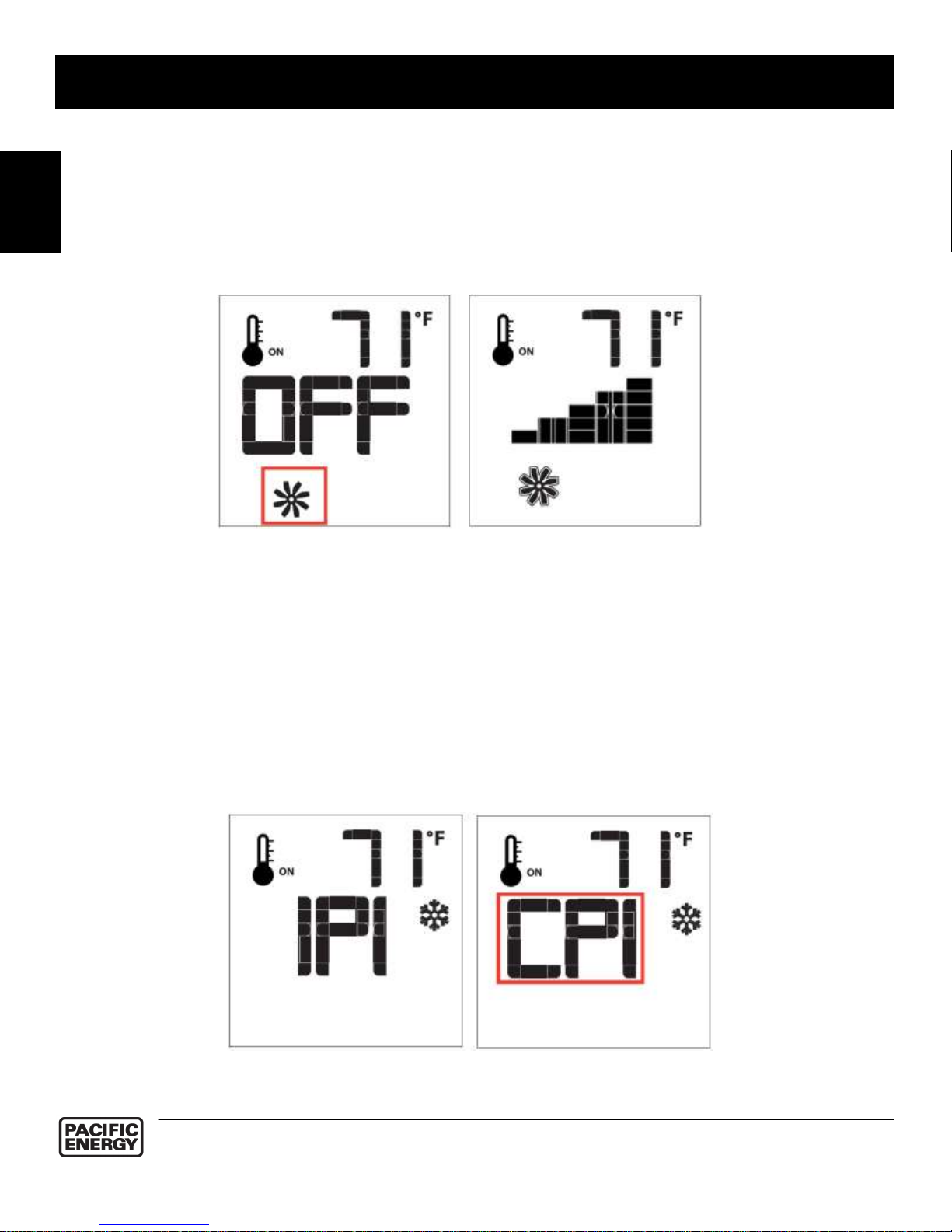
Comfort Fan Speed Control
If the appliance is equipped with a hot air circulating fan, the speed of the fan can be
controlled by the Proflame system. The fan speed can be adjusted through six (6) speeds.
To activate this function use the Mode Key (fig.1) to index the fan control icon (Fig. 10).
Use the Up/Down Arrow Keys (Fig.1) to turn on, off or adjust the fan speed (fig. 10). A
single “beep” will confirm reception of the command.
Continuous Pilot/Intermittent Pilot (CPI/IPI) selection
With the system in "OFF" position press the Mode Key (fig. 1) to index to the CPI mode
icon (fig.11).
Pressing the Up Arrow Key will activate the Continuous Pilot Ignition mode (CPI). Pressing
the Down Arrow Key will return to IPI. A single “beep” will confirm the reception of the
command.
Figure 10: Fan Control
Figure 11: CPI/IPI Selection
10
 Loading...