

Pacific energy Brentwood Gas Insert Installation And Operating Instructions Manual
IMPORTANT:
THESE INSTRUCTIONS ARE TO
REMAIN WITH THE
HOMEOWNER
WARNING: If the information in this
manual is not followed exactly, a fire or
explosion may result causing property
damage, personal injury or loss of life.
-- Do not store or use gasoline or other
flammable vapors and liquids in the vicinity
of this or any other appliance.
-- WHAT TO DO IF YOU SMELL GAS
- Do not try to light any appliance.
- Do not touch any electrical switch; do
not use any phone in your building.
- Immediately call your gas supplier
from a neighbour’s phone. Follow the
gas supplier’s instructions.
- If you cannot reach your gas supplier,
call the fire department.
-- Installation and service must be
performed by a qualified installer, service
agency or the gas supplier.
Brentwood
Gas Insert
SERIES A
VENTED GAS FIREPLACE
HEATER
INSTALLATION
AND
030603-24 Brentwood-A 5056.424
OPERATING
INSTRUCTIONS

Contents
Caution ...................................................................................................... 3
Safety ......................................................................................................... 4
Maintenance .............................................................................................. 4
Installation ................................................................................................ 5
Clearances ................................................................................................. 6
Venting....................................................................................................... 7
Gas Supply ................................................................................................ 7
Blocked Vent Shutoff System .................................................................. 8
Draft Inspection ........................................................................................ 8
Surround Assembly .................................................................................. 9
Log Set ..................................................................................................... 10
Glowing Embers ..................................................................................... 12
Levelling Legs ......................................................................................... 12
Glass Frame Installation ........................................................................ 12
Louver Installation ................................................................................. 13
Optional Radiant Overlay ..................................................................... 13
Lighting Instructions .............................................................................. 14
First Fire .................................................................................................. 15
Operation................................................................................................. 15
Primary Air Adjustment........................................................................ 15
Burner Removal ..................................................................................... 16
Propane Conversion ............................................................................... 17
Optional Blower ...................................................................................... 18
Replacement Parts .................................................................................. 20
Burner Replacement Parts .................................................................... 22
Label ........................................................................................................ 23
2
IMPORTANT: When lit for the first time, the
appliance will emit a slight odor for a couple of
hours. This is due to the curing of paints, sealants and lubricants used in the manufacturing
process. This condition is temporary. Open doors
and windows to ventilate area. If optional fan kit
has been installed, place fan in the "OFF" position. Smoke and fumes caused by the curing
process may cause discomfort to some individuals.
It is normal for fireplaces fabricated of steel to
give off some expansion and/or contraction
noises during the start up or cool down cycle.
Similar noises are found with your furnace heat
exchanger or cook stove oven.
Fig. # 1
Caution
FOR YOUR SAFETY - Do not install or operate your
Pacific Energy Brentwood Gas Insert without first reading
and understanding this manual. Any installation or operational deviation from the following instructions voids the
Pacific Energy Gas Stove Warranty and may prove hazardous.
This appliance and its individual shutoff valve must be
disconnected from the gas supply piping system during any
pressure testing of that system at test pressures in excess of 1/
2 psig (3.5 kPa).
This appliance must be isolated from the gas supply piping
system by closing its individual manual shutoff valve during
any pressure testing of the gas supply piping system at test
pressures equal to or less than 1/2 psig (3.5 kPa).
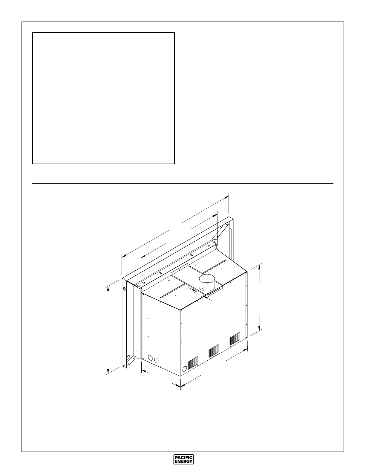
A
27 1/2"
2 1/2"
20 1/2"
B
12 1/2"
24 1/8"
Standard-size Surround Assembly, Plain and Embossed Bevelled Panels ............ 38 1/2" wide x 27 1/4" high
Over-size Surround Assembly, Plain Flat Panels ................................................... 44 3/4" wide x 30 1/2" high
AB
3
Safety
Maintenance
• Due to high temperatures, this gas appliance should be
located out of traffic and away from furniture and draperies.
• Children and adults should be alerted to the hazards of
high surface temperature and should stay away to avoid
burns or clothing ignition.
• Young children should be carefully supervised when
they are in the same room as the appliance.
• Clothing or other flammable material should not be
placed on or near the appliance.
• Any grill, panel or door removed for servicing the unit
must be replaced prior to operating. Failure to do so may
create a hazardous condition.
• Installation and repair should be done by a qualified
service person. The appliance should be inspected before
use and at least annually by a professional service person.
• More frequent cleaning may be required due to excessive lint from carpeting, bedding material, etc. It is imperative that control compartments, burners and circulating air passageways of the appliance be kept clean.
Caution: Turn off gas and electrical power supply and allow
ample time for unit to cool before servicing appliance. It is
recommended that this appliance and venting should be
inspected at least once a year by a qualified service person.
Do not use this heater if any part has been under water.
Immediately call a qualified service technician to inspect the
heater and to replace any part of the control system and any
gas control which has been under water.
Glass Panel:
Warning: Do not operate appliance with glass panel re-
moved, cracked or broken. Replacement of the glass panel
should be done by a licensed or qualified service person.
Do not strike or otherwise impact the glass in anyway that
may cause it to break. If the glass becomes cracked or broken,
it must be replaced before using the fireplace. Replacement
glass can be obtained from your nearest Pacific Energy
dealer. The size required is 13 3/4" x 27 3/8" x 5mm. Use
ceramic glass only. Do not substitute with any other type.
To remove broken glass, fold down the front bottom louver
to access the window latches.
Disengage the over-center latches by pulling each lever down
and forward. Grasp the sides of the frame and swing the
bottom out to clear. Lift up and forward to disengage from the
top. Remove all particles of glass. Be careful as they are very
sharp. Install new glass complete with gasket. Replace frame.
It is Pacific Energy’s policy that no responsibility is assumed
by the Company or by any of its employees or representatives
for any damages caused by an inoperable, inadequate, or
unsafe condition which is the result, either directly or indirectly, of any improper operation or installation procedures.
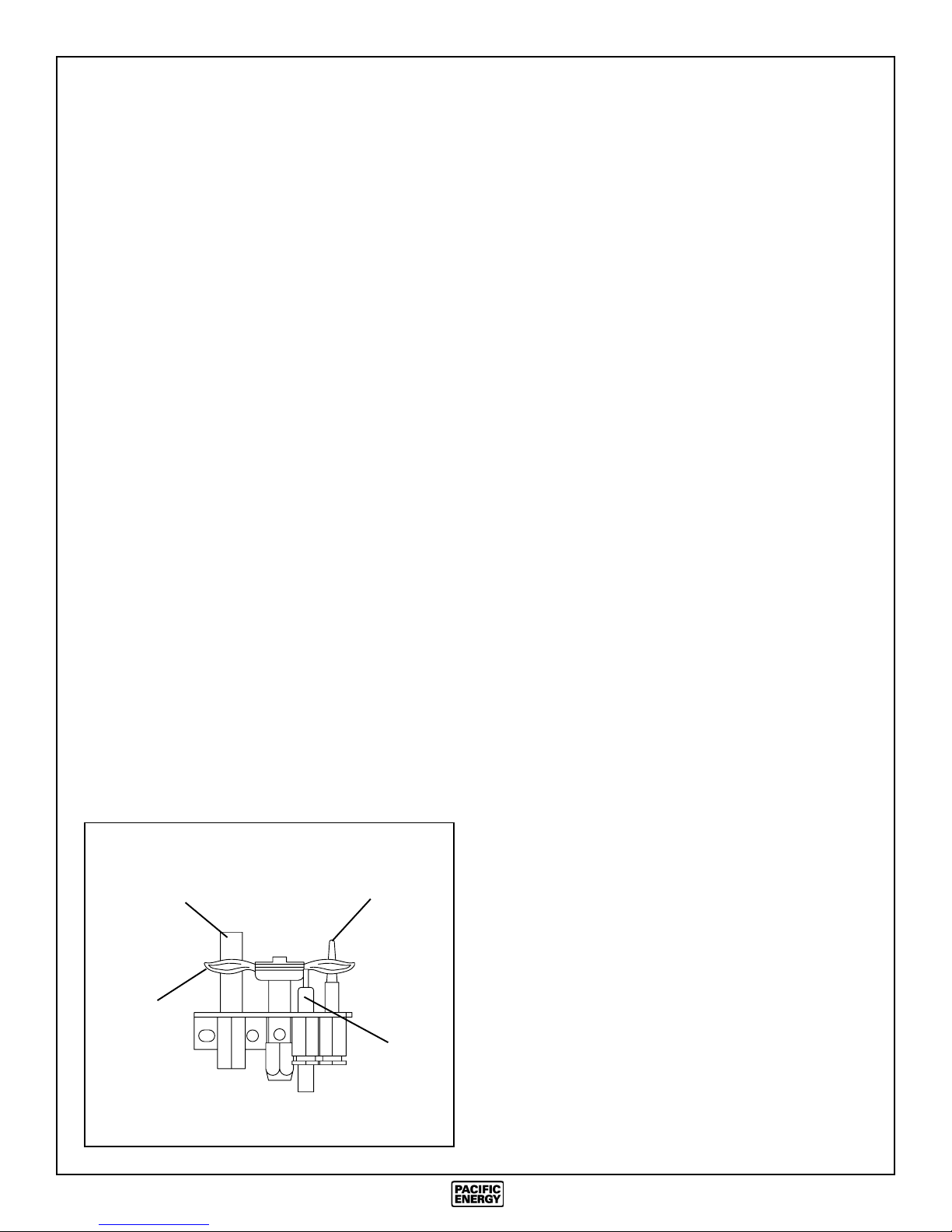
Fig. # 2
THERMOPILE
PILOT
FLAME
THERMOCOUPLE
ELECTRODE
Annual Inspection:
1) Clean louvers and air passage ways of excessive lint
buildup from carpeting, bedding material, etc. The flow of
combustion and ventilation air must not be obstructed.
2) Remove glass frame assembly and log set. Inspect logs
and burner assembly for lint and soot buildup. If excessive
buildup of soot is present, have a qualified service person
inspect and adjust unit for proper combustion. Clean logs and
burner with a vacuum cleaner, paying close attention to
burner ports.
3) Check the pilot system for proper operation (See Fig. #2).
4) Check that the chimney flue and its outlet are open and
free from blockage or debris.
5) Check glass panel gasket, replace if necessary.
Note: The appliance area must be kept clear and free from
combustible materials, gasoline and other flammable vapors
and liquids.
Periodically:
a) Viewing glass may be cleaned with glass cleaner.
b) Exterior porcelain enamel finish may be cleaned with soap
and water.
Note: Never use abrasives to clean this appliance.
4
Installation
Caution: A gas appliance must NOT be connected to a
chimney flue servicing a separate solid fuel burning appliance.
This appliance MUST be properly connected to a venting
system. This heater is equipped with a blocked vent
shutoff system designed to protect against improper venting of combustion products.
WARNING: Operation of this heater when not connected to
a properly installed and maintained venting system or tampering with the blocked vent shutoff system can result in
carbon monoxide (CO) poisoning and possible death.
Note: This appliance has a draft hood built in, and when
installed according to these instructions, the draft hood is in
the same atmospheric pressure zone as the combustion air
inlet to the appliance. Adequate combustion and ventilation
air must be provided for safe and proper operation.
The Brentwood Insert installation and venting must conform to the current CAN/CGA-B149 installation code (in
Canada) or the National Fuel Gas Code, ANSI Z223.1 1988 (in the USA), and approved per local codes. Only
qualified (licensed or trained) personnel should install
this product.
Fig. # 4
32 1/2"
32"
17"
The fireplace and its chimney should be swept and inspected.
The existing fireplace damper (if present) should be locked
open or removed completely if opening is too small for a 4"
flue liner to pass through.
Only listed trim kits shall be used in the installation of this
appliance. Draft Relief Openings must not be covered or
blocked.
Existing Fireplace
(Masonry or Factory Built)
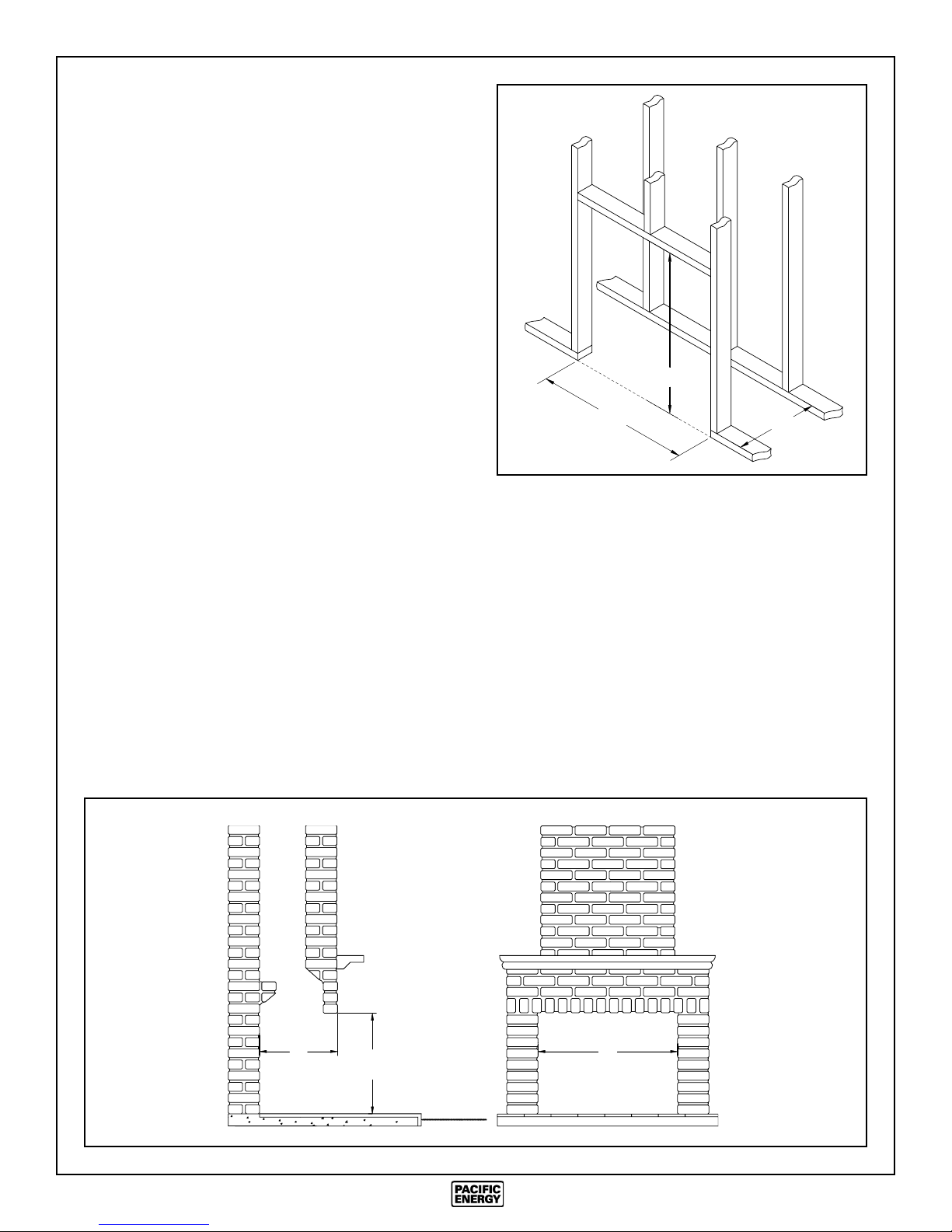
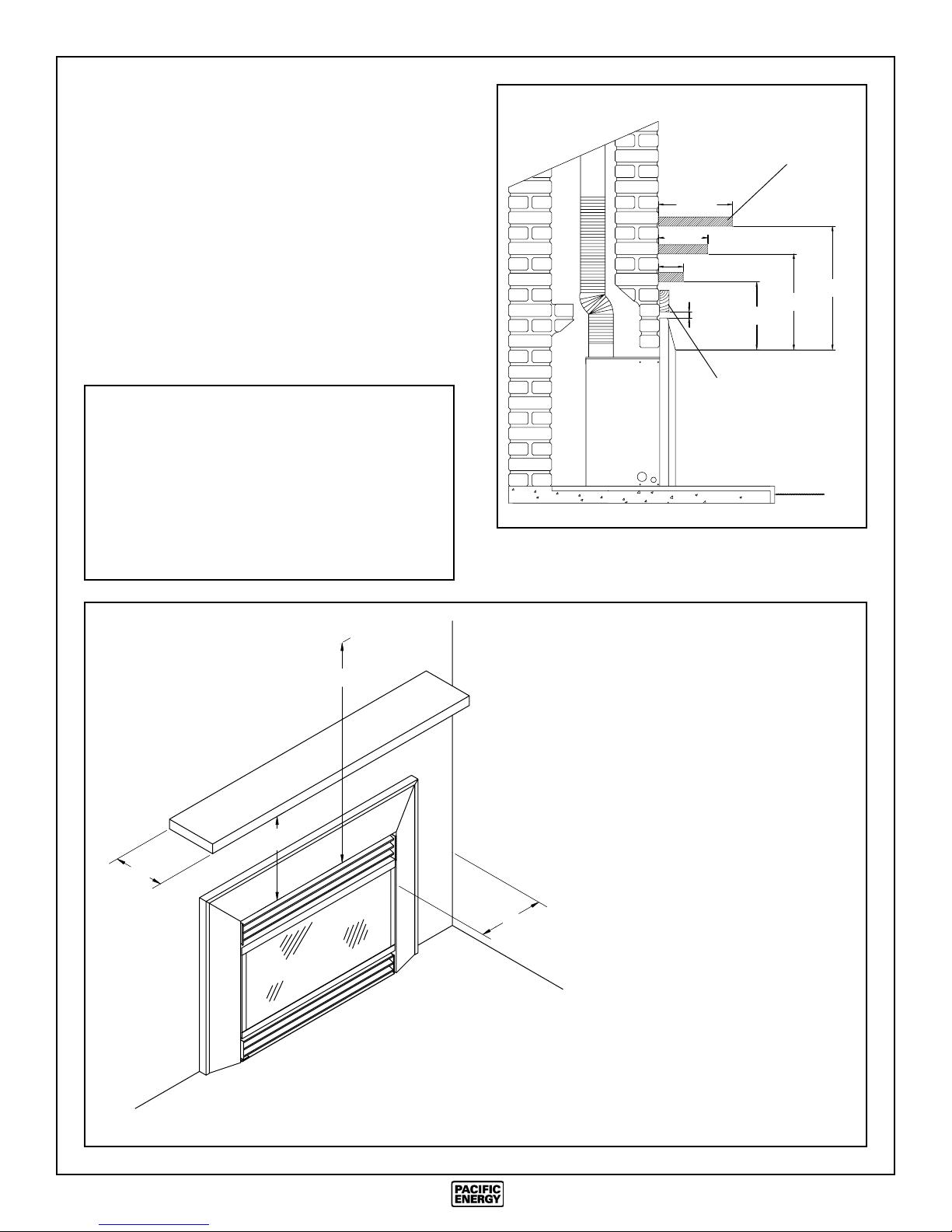
In order to sufficiently accommodate the Brentwood Insert,
the minimum size of the fireplace should be 28 inches wide,
21 inches high and 13 inches deep (Fig. #3).
Fig. # 3
Optional Zero Clearance Kit
The Brentwood Insert may be framed in with the optional
Mirage Zero-Clearance Kit (Fig. #4). Refer to the installation
instructions that are supplied with the kit for framing dimensions and precautions. This unit must not be installed with
zero clearance to combustible material without the use of the
kit.
13"
MINIMUM
21"
MINIMUM
28"
MINIMUM
5
Clearances
The Brentwood Insert is designed to be installed into a
masonry or a factory built zero clearance fireplace, or built in
with the optional Mirage Zero-Clearance Kit. The masonry
fireplace must be built according to the requirements of the
standards for chimneys, fireplaces, vents and solid fuel burning appliances, NFPA 211 (Latest Edition) or applicable
National, Provincial, State or local codes. The factory built
zero clearance fireplace and its chimney must be certified and
meet applicable National, Provincial, State or local codes.
The minimum clearances from the appliance to combustible
surfaces are shown on Fig. #5 and #6. Adequate clearances
around air openings and combustion air supplies are required.
Minimum Clearances to Combustibles:
(installed as a fireplace insert)
Adjacent sidewall: 9.5 in. (241 mm)
Ceiling to appliance: 38 in. (965 mm)
Mantel to appliance: see Fig. #5 and #6
Maximum mantel extension: see Fig. #5 and #6
Facing Side and Top
to appliance surround: 1 in. (25 mm)
Fig. # 6
VENTED
GAS INSERT
(305 mm)
8 in.
(203 mm)
12 in.
(102 mm)
4 in.
1 in.
(25 mm)
11 in.
(279 mm)
TOP OR SIDE
FACING
COMBUSTIBLE
MANTEL
15 in.
(381 mm)
13 in.
(330 mm)
Fig. # 5
A
CEILING
Mantel
B
38 in. (965 mm.)
Minimum Clearances to a Combustible Mantel
(installed as a fireplace insert)
"A" Mantel Width "B" Clearance
4 in. (102 mm) 11 in. (279 mm)
8 in. (203 mm) 13 in. (330 mm)
12 in. (305 mm) 15 in. (381 mm)
ADJACENT
WALL
9.5 in. (241 mm.)
6
Venting
Caution: Use only a flue liner system approved by the
local gas authority and install in accordance with the
manufacturers instructions. Consult local and/or national
building codes before altering fireplace.
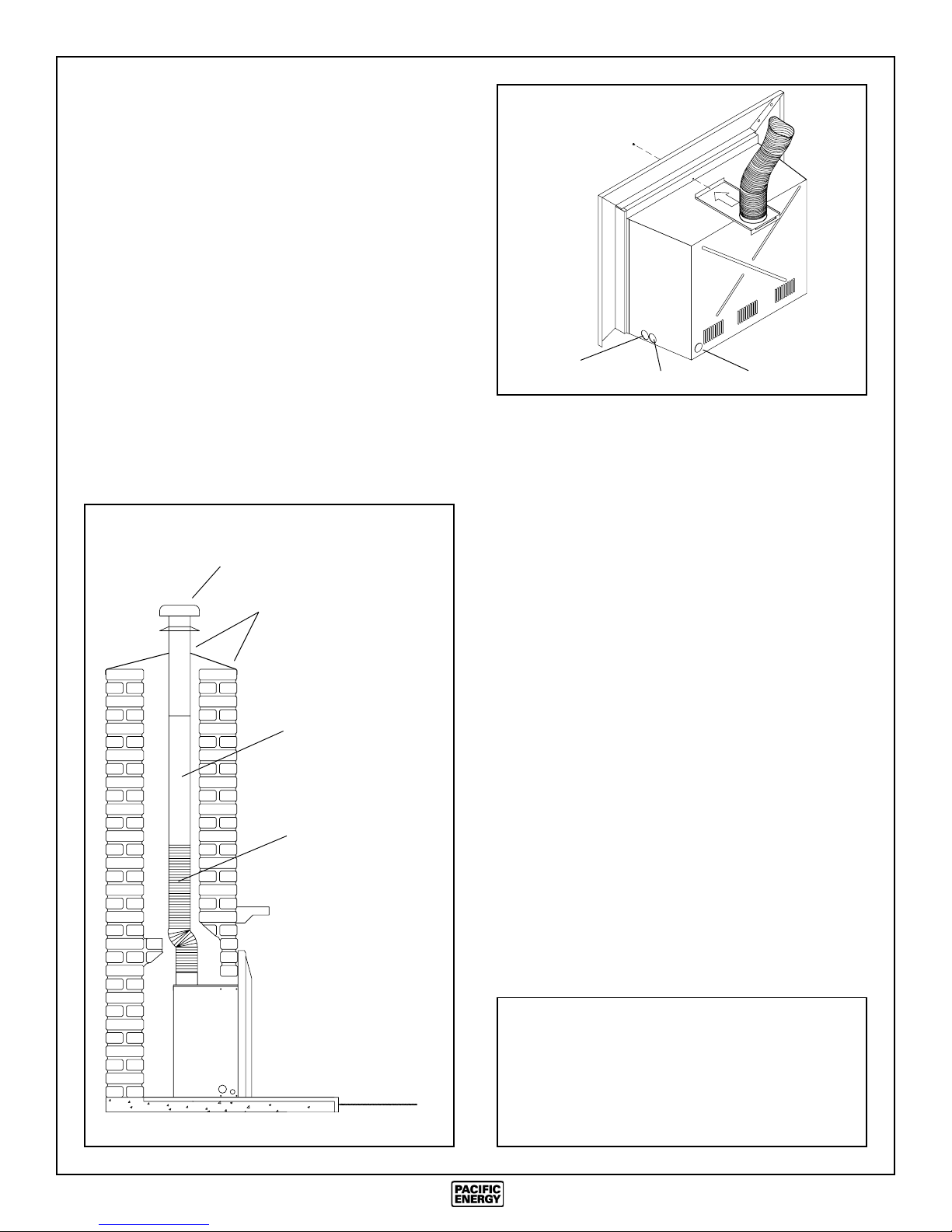
The chimney must be relined with a minimum 4" flue liner
(Fig. #7). A combination of 4" flex and rigid flue liner may be
used. (Consult local codes) The liner should extend from the
Insert collar to the top of the chimney. At the top of the
chimney, the air space between the new liner and existing
chimney must be sealed to prevent water from entering. Place
a flashing that fits snugly around the 4" liner on top of the
chimney. Caulk the flashing in place to seal any gaps.
Remove the screw located in front of the vent connector plate.
Attach the flex end of the flue liner to the collar on top of the
connector plate.
Fig. # 7
Fig. # 8
Optional
Blower
Cord Exit Rear Knockout
Position vent connector plate over top of unit as the insert is
pushed into the fireplace. Clip connector plate at the back of
the unit and attach to the front with screw provided (Fig. #8).
Leave the insert extending a couple of inches out of the
fireplace to allow for proper surround placement.
Gas Inlet
Cap
Seal Flashing
4" Rigid Liner
4" Flex Liner
Gas Supply
Caution: The gas line should be installed by a qualified
service person in accordance with all building codes.
Consult local and/or national building codes before proceeding.
The gas valve inlet accepts a 3/8" N.P.T. fitting. Correct gas
line diameter must be used to assure proper operation.
The gas control is equipped with a capture screw type pressure test port, therefore it is not necessary to provide an 1/8
inch N.P.T. plugged tapping pressure port for checking gas
pressure immediately upstream of the gas supply connection
to the appliance.
A knockout is provided at the bottom right rear of the
appliance as an alternate inlet for a gas supply line (Fig. #8).
To use this inlet, remove the knockout from the rear of the
appliance. Remove the plastic bushing installed in the side
and reinstall into the hole at the rear of the appliance.
An optional 24" long flexible connector (part #
GASC.GASCON) may be used for easy gas connection. This
connector may exit the appliance through either the right
front or right rear access holes.
Gas
Insert
Correct gas pressure requirement:
Natural Gas Propane
Min. Pressure 5.0" wc 11.5" wc
(For purpose of input adjustment)
Max. Pressure 10.5" wc 13.0" wc
Manifold Pressure 3.8" wc 11.0" wc
7
Blocked Vent Shutoff System
Installation
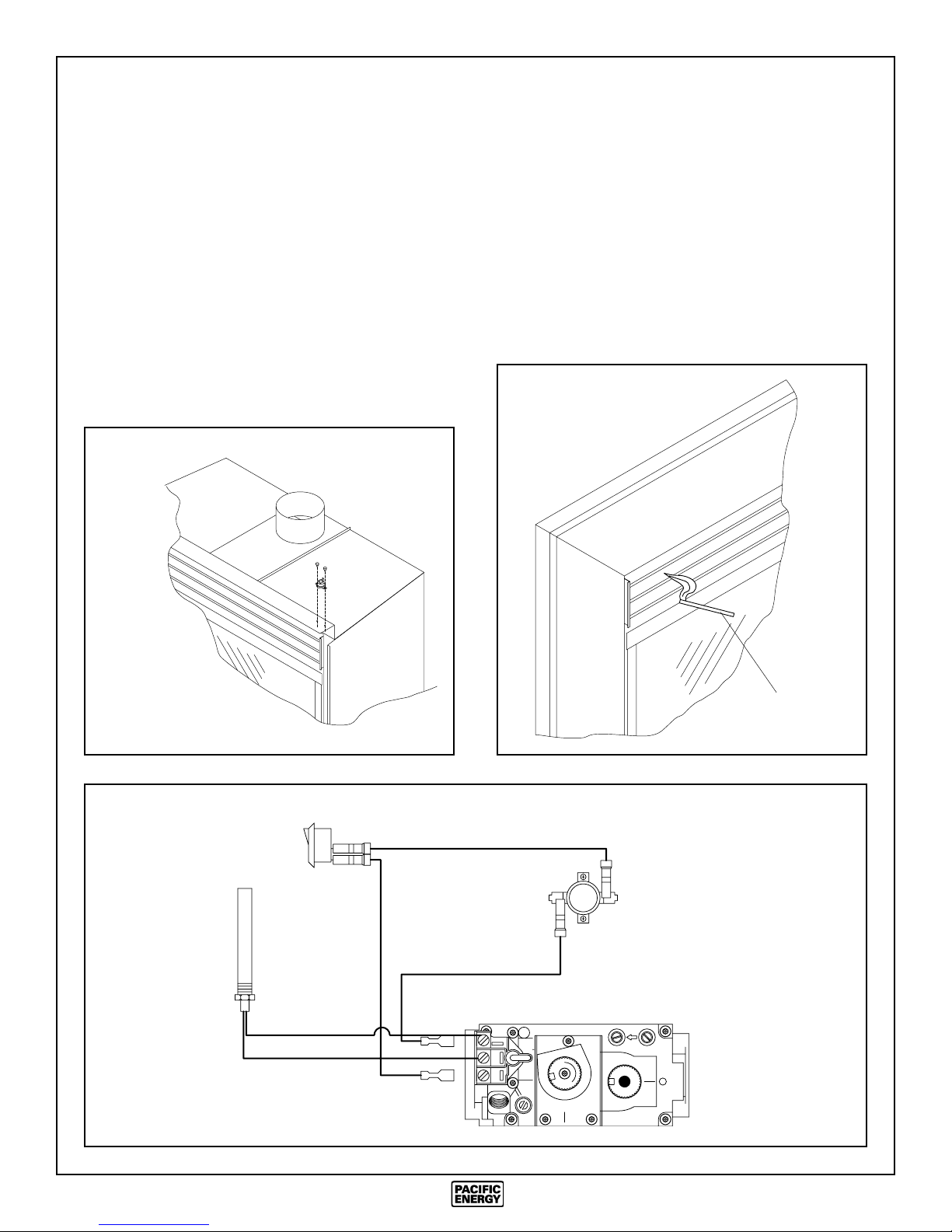
This appliance is equipped with a blocked vent shutoff
system. The switch assembly is shipped with the appliance.
1) Unravel wire, feed through front grommeted hole located
on the firebox support and right hand casing side.
2) Connect wire to "TPTH" and "TH" terminals on the gas
valve (Fig. #10).
3) Remove the two screws located at the uppermost right
front corner of the appliance.
4) Position the spill switch over the two holes and fasten in
place with the two screws (Fig. #9).
5) Install surround assembly. Connect remaining wire leads
to the rocker switch on the surround trim.
Fig. # 9
Draft Inspection
This appliance must be connected to a venting system with
adequate draft to ensure safe and proper operation.
To inspect vent operation:
A few minutes after the appliance is lit, insert a smoke stick
between the middle and top louver (Fig. #11). If the smoke is
drawn in, the venting system is operating properly. If the
smoke is not drawn into the opening, turn the unit off and
inspect the venting system for blockages or restrictions.
Fig. # 11
Fig. # 10
Thermopile
Rocker Switch
Smoke Stick
Spill Switch
THTP THTP
O
P
I
L
O
T
AE
L
H
I
F
O
F
P
I
L
T
O
N
O
Gas Valve
8
 Loading...