

Page 1

PAC-12 Kit Contents
Part Quantity
Screws: 8/32 x 3/8” 8**
Screws: 8-32 x 5/16” 2
Screw: 8-32 x 1/4” 1
#8 internal tooth washers **
#8 solder lug ring terminals 6
Bolt: Aluminum, 1/4-20 x 1.5” 1
1/4” internal tooth washer 1
Nut: Aluminum hex, 1/4-20 1
Stainless wing nut, 1/4-20 1
BNC connector 1
BNC mounting plate 1
Stranded wire red and green 3”
#18AWG enamel wire for standard coils or **
Tinned copper wire for multi-band coil **
Ground coupling radial kit 1 1
Feed point insulator PVC tube 1
Feed point insulator end caps 2
Full size coil kit and **
2 Compact coil kits or **
Multi-band coil kit **
Aluminum Rods 12” 2
Aluminum hex coupling nut 1
72” telescoping antenna 1
Antenna whip adapter 1
Ground spike 1
Tools Needed
Soldering iron
Phillips screwdriver
Wire stripper
Wrenches, 7/16” and 1/2”
Terminal crimp tool
Pliers
Solder
PAC12_Manual
V3.0_20160712
Page 2

** Note, the quantity of these items in the kit depend on whether the multiband coil or standard
coil kit is purchased.. All antenna hardware is the same for both kits, only the coil kit hardware
will vary.
Feed point insulator assembly
Parts:
PVC base tube (1)
Aluminum end caps (2)
8-32 x 5/16” Phillips head screws (2)
#8 star washers (2)
#8 Size crimp ring terminals (2)
BNC mounting plate (1)
BNC connector (1)
Red and green stranded wire (3”)
Stainless wing Nut (1)
1.5” ¼-20 aluminum bolt (1)
¼” aluminum nut (1)
¼” star washer (1)
Start by inserting the 2 smaller aluminum end caps into the ends of the PVC tube to check the fit.
Align the holes and secure using the two 8-32 x 5/16” stainless screws. Be sure to use the
correct screws, as the longer 3/8” screws supplied for the loading coil will interfere with the
threaded sections screwing into the end caps.
The screws should start smoothly and should not require much effort to tighten. If otherwise,
make sure the threads are aligned properly. Be careful not to over tighten as the end cap metal is
aluminum and is it possible to strip the threads. It will be necessary to remove the screws later
but they are installed now to prevent crushing the tube while installing the BNC plate.
Using the ¼ -20 x 1.5” bolt, lock washer and nut, attach the
BNC mounting plate to the feed point insulator PVC tube by
inserting the bolt through the PVC tube and then through the
aluminum bnc mounting plate.
Secure with a lock washer and the ¼-20 nut. Tighten from the bolt head side while holding the
BNC plate in position.
PAC12_Manual
V3.0_20160712
Page 3

Mount the BNC in the plate and secure using its nut. The BNC
connectors may be supplied with a red rubber gasket that should
be removed before installation
Install the stainless wing nut screw onto the end of the 1/4-20
bolt in the center. It is used to secure the ring terminals for
connection of the radials.
Once the BNC is securely installed, use the sections of green
and red wire to connect from the BNC to the crimp terminals.
The red wire goes the center terminal of the BNC. The red wire
will indicate the antenna end of the feed point.
Measure the necessary wire and crimp and or solder the
terminals to the wire. Next, remove each screw and place it
through the ring terminal and reattach to the end cap.
This completes the assembly of the feed point insulator. Check for continuity using an
ohmmeter between the center and shell of the BNC and the end caps of the antenna. Resistance
readings should be no more than one or two ohms including the meter lead resistance. Also
verify that there is no short by checking resistance between the end caps or across the BNC.
Resistance should read very large or infinite here.
Note that the feed point insulator is symmetric. This feature allows the antenna to be used as a
dipole as well as a vertical. When used as a dipole, the bolt in the center serves as the antenna
support point for attaching to a mast. When using the antenna as a vertical, make sure to install
the feed point insulator with the center conductor of the BNC connected to the antenna and the
shell to the radials.
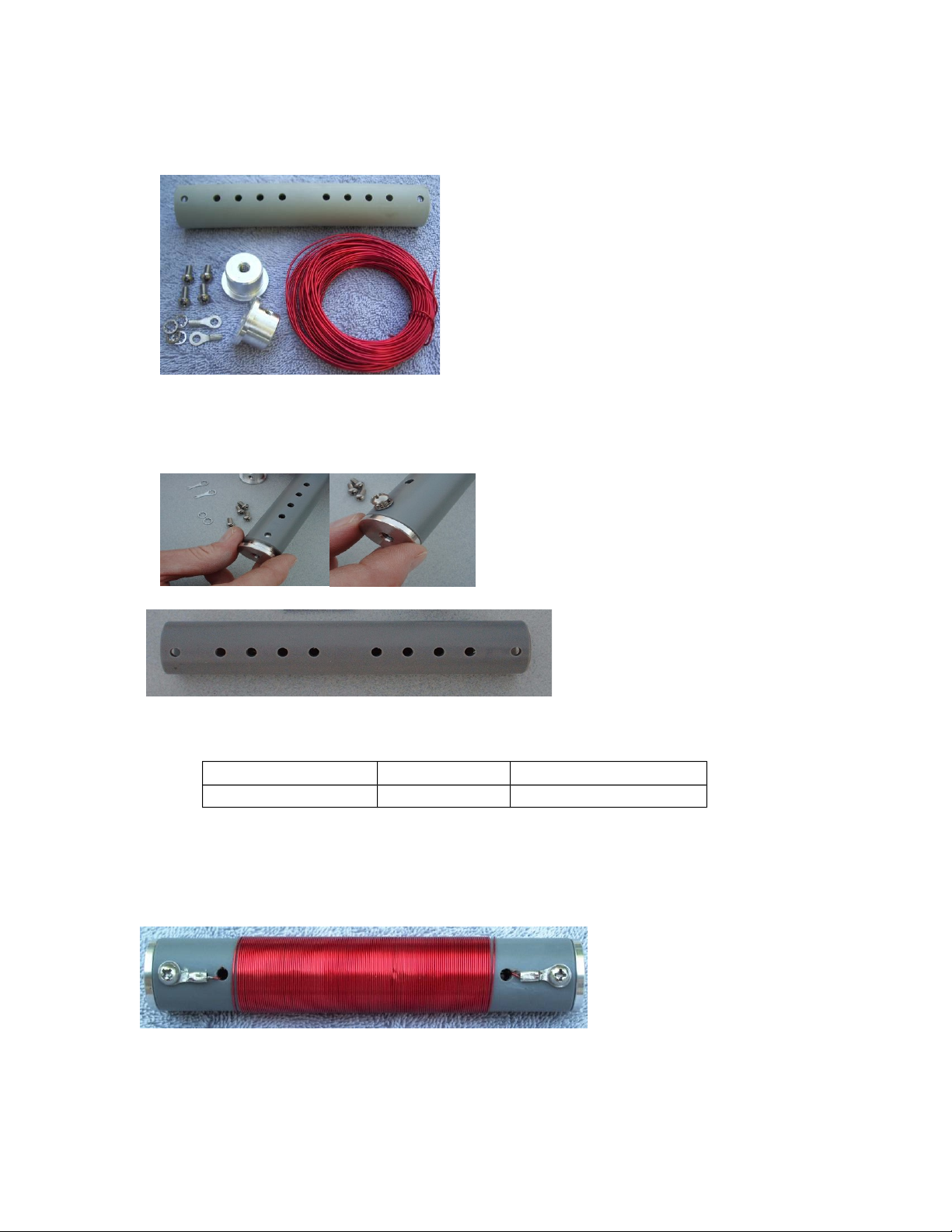
PAC-12 standard coil kit assembly
Full size coil kit assembly
Note: If assembling the multi-band coil version, skip ahead to that section.
Parts:
PVC coil form, light gray (1)
Aluminum end caps (2)
8-32 x 3/8” Phillips screws (4)
#8 internal tooth lock washers (4)
#8 crimp ring terminals (2)
#18 enameled copper wire
PAC12_Manual
V3.0_20160712
Page 4
This is what the coils will look like when completed. The
A B C D D C B A
instructions below will step through the process of assembling
and winding the coils for your PAC-12.
The loading coils are assembled using the 2 larger end caps, the larger light
gray PVC coil form, 4 of the 8-32 x 3/8” screws and four #8 lock washers.
Insert the end caps and align the holes
Install these one screw and washer in each end cap on the same side of the coil
form. The other side will be used for securing the coil windings.
Full Size Coil Form
Once the end caps are installed, the coil form is
ready for winding the coil. The coil form has a
series of holes used to secure the ends of the
winding. Depending on which band you plan to
construct the coil for, you will use different sets of
the holes. The full size coil form can be built for any band but it is typically constructed for the
40 or 60M bands and the compact coil kits used for higher bands. The charts show which set of
holes to use for each band.
Chart for full size coil winding
Band
Meters
10 1 or jumper D
12 4 D
15 8 D
17 11 D
20 17 D
30 29 C
40 57 B
60 93 A
Turns to
wind
Hole set(see
photo)
PAC12_Manual
V3.0_20160712
Page 5

Compact coil kit assembly
Chart for compact coil winding
Band
Meters
10 1 or jumper B
12 4 B
15 8 B
17 11 B
20 17 A
30 29 A
Turns to wind Hole set
For winding the compact coils, use the same
technique and winding chart as for the full size 6”
coils. There is sufficient space on the form for
winding coils for 30M and higher.
The coil forms have 4 holes used for securing the ends
of the coils during and after winding. See the photos
and chart below for information:
(see photo)
This drawing shows how the wire is
routed when winding the coils. When
using the inner sets of holes, the wire can
be run through the hole set at the end of
the coils and then looped back through the
next hole set to provide additional security
and protect the wire.
The next photos illustrate the assembly of the compact coil form. The assembly process for the
full size coil is the same except that different hole sets may be used
First, tin the end of the enamel wire by heating with a
blob of solder. Feed extra solder in as necessary and
you will see the enamel begin to peel off and the solder
will coat the bare end. Tin approximately 0.25 to 0.5”
of the wire to prepare it for connection at the crimp
terminal later.
PAC12_Manual
V3.0_20160712
Page 6
Determine the hole set to be used from the winding
chart and pass the end of the enameled wire through one of
the holes so that is passes through the coil form from one side
to the other.
If the inner set of holes are being used, pull enough extra
wire to loop back through hole set A and to reach the screw
on the end of the coil form.
Attach a ring terminal by crimping and or soldering to the
tinned end of the copper wire. Be sure that the terminal is
securely attached to the wire.
Attach the ring terminal on the end of the wire to the end
cap of the coil with a screw and lock washer.
Begin winding the coil by turning the form while feeding the wire onto it.
Using the thumb and forefinger will work to guide the wire. Wind the
specified number of turns on the coil. A turn counts each time the wire
loops completely around the coil from the starting point. If in doubt, put
on extra turns as it is easier to remove an extra turn than to rewind the coil.
When finished, cut off the excess wire leaving about 6”. This will allow
the end to be passed back through the coil form.
While winding, you may find it necessary to occasionally push the turns together for a tighter
coil. On most coils except for 60M, there is extra space and this is not strictly necessary, it just
improves the appearance.
Pass the wire back through the coil form and align with the hole in the
end cap. Check the required length to reach the end cap plus enough
to go around the screw, cut off the excess and tin the end.
If you do not plan to optimize the coil tuning, simply attach the ring
terminal by crimping and or soldering
PAC12_Manual
V3.0_20160712
Page 7
To allow adjusting the coil turns, attach this end as shown in the photo.
This is temporary to allow removing turns if necessary to optimize the
coil.
Coil Optimization
Optimizing the coil is done by assembling the antenna, and checking with an antenna analyzer or
SWR bridge. The coil should be adjusted so that the whip has approximately one half section
collapsed at the low frequency end of the band. This can be done after the antenna assembly is
complete and ready for testing.
This is how a compact coil looks when completed.
This coil is wound for 30 meters.
A complete set of coils for 40, 30, 20, and 17M
Note in the photos of the entire coil set how the wires pass into the form on one
side and along the form on the opposite side to secure the coils. From one side
you should have the coil ends disappearing into the coil form and from the
other, the wires emerge, lie along the coil form and re-enter at hole set A, pass
through and connect at the solder lugs. If using the inner hole sets, you can loop
the wire back and forth through the unused hole sets to prevent a long run down
the coil form on one side.
Secure the terminal and fold the wire down to lie flat along the terminal.
Once compete, check the end-to-end resistance of the coil using an ohmmeter. It should be no
more than one or two ohms or less for any of the coils. If a higher resistance value is noted,
recheck the tightness of the screws and that the solder joint and loop make good contact.
PAC-12 Multi-band Coil Kit
Assembly
The PAC-12 multi-band coil kit is designed to replace a fixed
coil in the antenna system to provide continuous tuning from
40 meters through 10 meters. The coil kit is wound with tinned
copper wire and has a tap lead to adjust the effective inductance and tune the resonant frequency
of the antenna system.
PAC12_Manual
V3.0_20160712
Page 8

Contents:
1 PVC coil form
2 aluminum coil end caps
4 #8 screws and washers
3 crimp or solder lugs
1 roll of #18 tinned copper wire
1 clip lead
1” heat shrink tubing
Coil Assembly:
To assemble the coil kit, start by
feeding the bare #18 wire
through the holes at the end of
the lengthwise slot along the coil
form. Pass the wire into the hole
through the tube and out the
other side. One of the ring
terminals should be installed on
the end of the wire by crimping
and/or soldering the terminal to
the wire end.
Next, install the end caps into the PVC tube and secure with 2 screws
and washers on the same side of the coil as the lengthwise slot.
A #8 screw with washer can then be inserted through the terminal
end and attached to the other hole in the aluminum end cap through
the coil form side.
Once the end of the wire is secured,
begin winding the wire around the tube
by laying it into the grooves formed by
the threads cut into the coil form. Maintain tension on the wire as
you wind. If you need to take a break, secure the wire temporarily
with tape or other method so that the wire will not become loose.
Continue winding to the other end of the tube until you have reached
the end of the threaded area of the form. It is important to wind all
the way to the end of the threaded area as this ensures sufficient number of turns on the
coil.
Should the wire be loose on the coil winding, you can use your hand to work it in a twisting
motion to remove the slack and pull the excess at the end of the coil.
PAC12_Manual
V3.0_20160712
Page 9

Next, leave a few inches (~6) beyond the last turn on the coil and cut the wire from the spool.
This end should be long enough to be passed through the holes in the form. Push this end trough
the holes at the end of the coil as was done when starting the coil winding so that it comes out
the other side. Secure the end with another crimp terminal and cut off any extra wire. Secure the
end by soldering or crimping the wire to the terminal and connect with a screw and washer.
Coil Tap Assembly
The flying tap lead is created using the test clip lead with crimp
terminal placed on the end and covered with heat shrink tubing.
First, strip approximately 1/4” of the insulation from the end of
the clip lead wire.
NOTE: Be sure to slip the shrink tubing over the wire before
attaching the ring terminal.
Next, attach the ring terminal on to the stripped end of the wire by
crimping and or soldering.
Once the wire is crimped, slide the head shrink down and over the
crimped area of the ring terminal and apply heat to shrink the
tubing to secure the wire and protect from flexing.
Once the lead is complete it should be secured under one of the screws at the end of the coil
form as shown below.
This completes the
assembly of the PAC12 Multi-band coil.
This is how it should
look when completed:
PAC12_Manual
V3.0_20160712
Page 10

Operation with multiband coil:
The multi-band coil kit is installed into the PAC-12 antenna system by screwing it onto the top
of the base rods and screwing the whip adapter and whip into the top end.
The multi-band coil can be installed either with the tap lead up or down. The coil can be
adjusted for operation on any frequency between 40M and 10M. For operation on 10M, the
telescoping whip may need to be collapsed a bit as the antenna may be a bit too long for
resonance.
The antenna should be tuned by moving the tap position, checking the SWR and if necessary
adjusting the whip length to achieve a good match (<2:1).
To insert the tap, grip the clip and press on the back end to expose the metal end. Align it
parallel to the direction of the winding and while holding it extended, insert it between the turns
of the coil in the desired area, rotate it by a quarter turn so that the metal end is under the wire
and then release. Reverse this process to remove the clip.
Check the SWR and move up or down the coil as needed to achieve a match. See the chart and
sketch on the next page for guidance in finding the tap points.
PAC12_Manual
V3.0_20160712
Page 11
40M
The chart and sketch are included on this page for assistance in
finding the tap points for each band.
This page can be printed and held next to the coil to aid in
determining the tap location.
This guide may be cut out and laminated and carried with the kit to
aid in coil adjustment.
Note: The tap locations shown are approximate and will vary with
location, length of radials and surroundings.
Approximate tap points with tap
lead end of the coil oriented up as
30M
20M
17M
shown here.
Band Coil Tap Position
40M: 10 turns from top
30M: 57 turns from top
20M: 22 from bottom
17M: 10 from bottom
15M: 6 from bottom
12M: 1 from bottom
10M: 1 from bottom*
*whip partially collapsed
15M
12/10M
PAC12_Manual
V3.0_20160712
Page 12
A B C D D C B A
80 Meter Coil Assembly
Note: This coil kit is an option, not part of the standard kits.
Parts:
PVC coil form, light gray (1)
Aluminum end caps (2)
8-32 x 3/8” stainless Phillips screws (4)
#8 internal tooth lock washers (4)
#8 ring terminals (2)
#22 insulated copper wire
The coil is assembled using the 2 larger end caps, the larger light gray PVC coil form and 4
of the 8-32 x 3/8” screws. Four #8 lock washers and 2 #8 ring terminals are used. Two
lock washers go on one side to secure the screws and the 2 ring terminals are used for
connecting the coil windings.
Insert the end caps, align the screw holes
and insert the screws.
Once the end caps are installed,, the coil is ready for winding.
The coil form showing holes to secure windings. For 80M hole set “A” will be used.
Band Meters Turns to wind Hole set(see photo)
80 145 A
Start by winding 145 turns on the coil. This should almost entirely fill the space between
the hole set (A) At this point, you may prefer not to solder one end of the coil. This will
allow adjusting the coil without unsoldering. Once you are happy with the coil you may
choose to crimp or solder the wires to lugs or leave as is.
The Completed 80 meter coil
PAC12_Manual
V3.0_20160712
Page 13

Telescoping Antenna Assembly
Parts:
72” telescoping whip (1)
Aluminum whip adapter 1)
8-32 x 1/4” Phillips head screw (1)
To assemble the whip, slip it into the whip adapter until it
hits bottom. If the fit is tight, it may require rotating the
whip slightly while inserting.
Once in place, secure using the 8-32 x 1/4” Phillips head
screw. This completes the whip assembly.
Radial kit
Parts:
16-conductor ribbon cable
4 -1/4” ring terminals
The ribbon cable supplied is used to produce a set of
short radials. These are intended for operation when
the antenna is ground mounted as an earth coupling
system.
PAC12_Manual
V3.0_20160712
Page 14

First, separate the 16-conductor ribbon cable into 4-conductor
sections giving a total of 4 sections of 4 wires each.
Strip the ends of the wires back a half-inch or so,
and twist them together.
Crimp the terminal and use electrical tape or
heat shrink tubing to strain relief the connection.
Separate the sets of 4 wires into two wire sets
from the end up to the strain relief on the ring
terminal.
This will form 2 radial wires connected to each
ring terminal. Each radial will have 2 parallel conductors.
PAC12_Manual
V3.0_20160712
Page 15

Cautions
As with any antenna, do not use near electrical wires either overhead or
buried.
Use caution whenever using the ground spike to make sure the area is
clear of buried plumbing or electric wires. If in doubt, do not use the
ground spike.
Also, use caution with the ground spike as the end is sharp and can cause
injury. Do not allow children to play with the antenna.
Assembling the PAC-12
To assemble the antenna, gather the parts that
have been prepared. In addition to the
components that you have already assembled,
you will need the 2- 12” aluminum rod sections,
coupling nuts and the ground spike (if ground
mounting the antenna).
If it is available, some aluminum antioxidant
grease will make assembly and disassembly of
the antenna easier as well as maintain good
conductivity between the sections. Small tubes
of a suitable material can be found in the
electrical sections of most hardware stores
where it is sold for use with aluminum house
wiring and interconnects. Alternatively, a small
amount of dielectric grease or even engine oil
will work. Be sure to wipe off any excess to
reduce the chance of it collecting dust.
Screw the ground spike into the grounded side
(BNC shell) of the feed point adapter. Screw a
12” rod section into the other end. Place a
coupling nut on this rod and add the second
section of rod. The loading coil screws onto the end of the second rod. Tighten all
connections securely but do not over tighten as the threads may be damaged.
PAC12_Manual
V3.0_20160712
Page 16
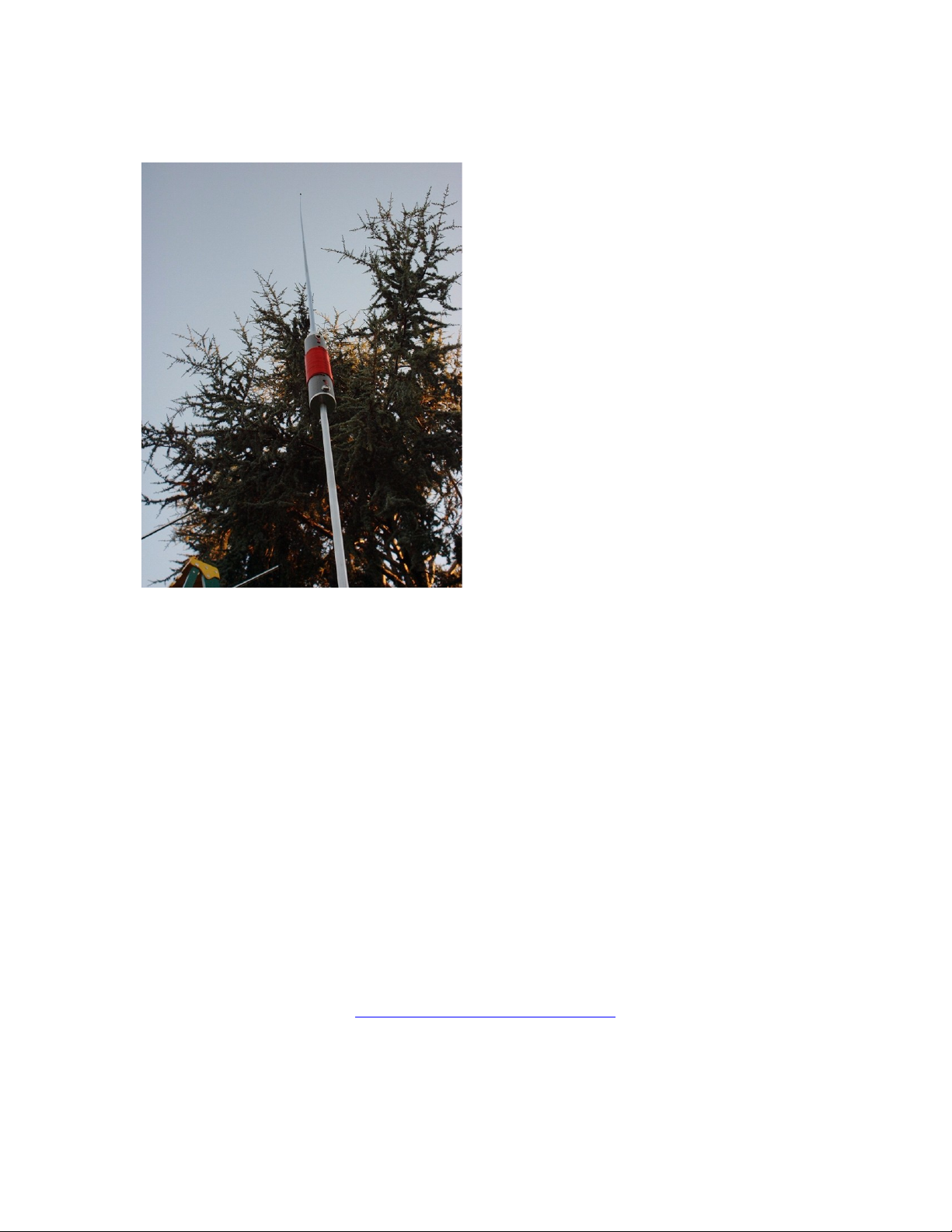
Connect the whip to the other end of the coil by screwing the adapter into the threaded
opening in the coil. This completes assembly of the antenna.
For operation, connect the radial wires or
counterpoise to the ¼” bolt in the center of the
feed point using the supplied wing nut to
secure the ring terminals on the radial wires.
Deploy the radials around the base of the
antenna as uniformly spaced as possible.
The antenna will also mount on any standard
camera tripod using a 1/4-20 thread.
If mounted above ground, it will usually be
necessary to use resonant radial wires for best
performance. The radial kit supplied is
intended for close ground mounting and is
designed for coupling to the ground under
such conditions.
When the ground is not present, longer,
resonant radial wires will improve
performance.
Testing
Assemble the antenna and test for lowest SWR. You may need to collapse up to one full
section or more of the whip to achiever a low SWR at the low end of the band. The coil
turns specified above will put the SWR minimum at or near the low end of each band. To
go higher, you simply collapse the whip. You may need to collapse up to one full section or
more of the whip to achiever a low SWR at the low end of the band. If more than one
section is collapsed, remove a turn from the coil and retest. Once you are happy with the
coil, you can solder the end to a solder lug or just leave it looped under the screw.
Thank you for purchasing the PAC-12 antenna kit, please contact us via email if we can
help in any way.
The latest version of this manual will also be posted on our website.
James
KA5DVS
Email:
qrpkits.com@gmail.com
PAC12_Manual
V3.0_20160712
Page 17

Website:
www. qrpkits.com/pac12.htm
Frequently asked questions and hints
Q How long does it take to build the PAC-12?
A. The antenna kit can be assembled in around one to two hours using simple hand tools
and a soldering iron.
Q: How much power does it handle?
A: The PAC-12 is rated to 100W of power when adjusted to a matched condition.
Q. What is the difference between the fixed coils and the multi-band version?
A. The only difference is the coils used. All other hardware is identical and it is possible
to use both single band and multi-band coils depending on the application and operating
situation.
PAC12_Manual
V3.0_20160712
 Loading...