

Page 1
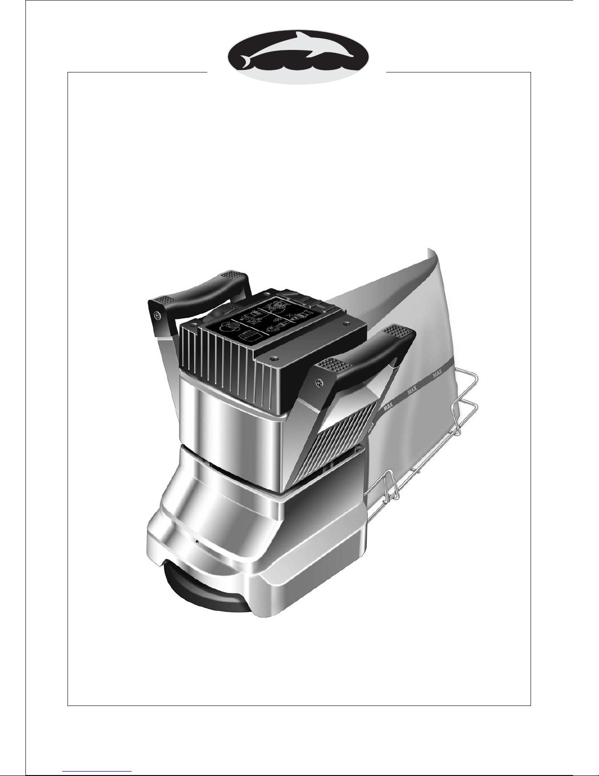
Wolverine PF7
Edger Sander
OWNERS MANUAL & OPERATING INSTRUCTIONS
MAY 2010 REF. 69 PART # 000510
From Serial Number
04453 (110 Volt)
PACIFIC
Page 2

NORTH AMERICAN SAFETY INSTRUCTIONS
USE AND APPLICATION
WARNING: This floor sanding machine must be grounded.
This floor-sanding machine shall be grounded while in use to protect the operator from electric
shock. The machine is provided with a three-conductor cord and a moulded three-contact
grounding type attachment plug to fit the proper grounding type receptacle. The Green (or
Green and Yellow) conductor in the cord is the grounding wire. Never connect this wire to other
than the grounding pin of theattachment plug.
This floor-sanding machine is provided with an attachment plug as shown in sketch A. It is
intended for use on a nominal 120 volt circuit. If a properly grounded receptacle as shown in
sketch A is not available, an adaptor as shown in sketch 'C' should be installed as shown in sketch
B if the outlet box that houses the receptacle is grounded. Be sure to fasten the grounding tab with
a metal faceplate screw.
Floor sanding can result in an explosive mixture of fine dust and air. Use floor-sanding machine
only in a well-ventilated area freefrom any flame or match.
Moving Parts - to reduce the risk of injury, unplug the machine before replacing abrasive sheets
or carrying out any form ofadjustment or servicing.
WARNING:
WARNING:
Risk of explosion.
Of potential injury.
This machine is intended for commercial use connected with the laying and maintaining of wooden floors and
decks.
These types of surfaces may be found both in commercial andhousehold environments.
ATTACHMENT PLUG
SKETCH ‘C’
METAL
SCREW
COVER OF GROUNDED
OUTLET BOX SKETCH ‘B’
ADAPTER
GROUNDING
MEANS
COVER OF GROUNDED
OUTLET BOX SKETCH ‘A’
GROUNDING PIN
Manufactured in UK © Hiretech
Page 3
CONTENTS
WARNING
MAINS CABLE WIRING - PLUG
SPARE PARTS
SPECIFICATION
SAFETY
SET UP
PREPARATION
OPERATION
FLOOR SANDING TECHNIQUE
FLOOR TYPES
i
i
I
1
1
Assembly and Transport 2
Installing Abrasive Disc 2
2
2,3
Drum Floor Sander 4
Edger Sander 4
Hand Sanding 4
Sanding Plank & Strip Floors 4
Parquet & Block Floors 4
6
General 7
Visual Inspection 7
Dust Control System 7
Drive 7
Lubrication 7
Care of Motor 7,8
Sanding Pad Removal & Replacement 8
Sanding Pad Trimming 9
Adjusting the Castors 10
Electrical Testing 10
11
12
13
14
ABRASIVE PAPER GUIDE
SERVICE AND ROUTINE MAINTENANCE
TROUBLE SHOOTING
WOLVERINE PARTS DRAWING
WOLVERINE PARTS LIST
WOLVERINE CIRCUIT DIAGRAM
SERVICE & REPAIR 16
WARNING
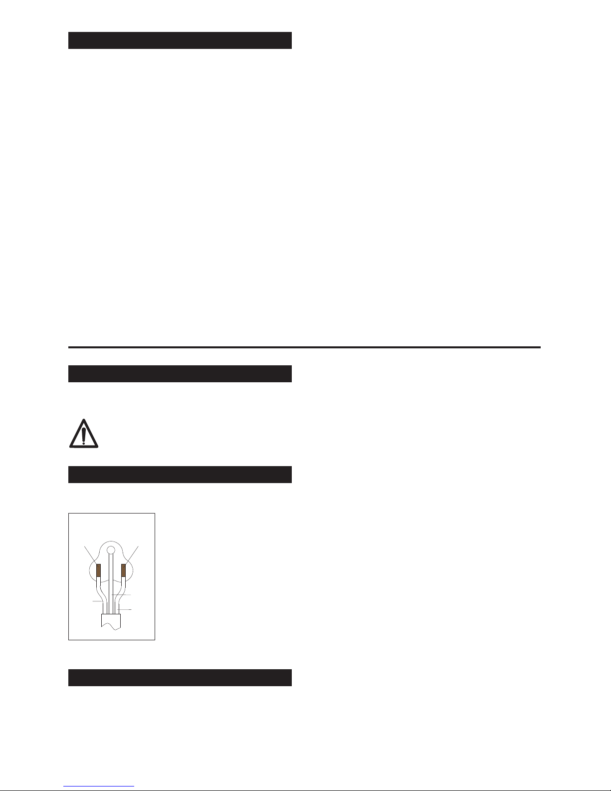
MAINS CABLE WIRING - PLUG
For safe operation of this machine, readand understand all instructions. Look for the‘warning/caution’symbol.
This symbol means that if you do not follow the instructions injury can occur to the operator and
damage to themachine and floor may result.
Pacific Floor Care reserves the right to make changes or improvements to it's products without prior notice.
i
NORTH AMERICA
BLACK
WHITE
GREEN
BRASS
TERMINAL
SILVER
TERMINAL
SPARE PARTS
Use Pacific Floor Care genuine spare parts only for service and repair. Use of non-approved parts will void the product
warranty. See the back cover of this manual for the terms and conditions of the Pacific Floor Care Limited Warranty.
Page 4

SPECIFICATION
The Pacific Wolverine PF7 Edger Sander will sand
hard and soft wood floors, cork and composition
floors and any solid wood surface that requires rapid
sanding and leveling to a fine finish. Ideal for
confined areas such as closets and stair treads the
will sand right up to the edge of
a floor without damage to the base (skirting) board.
Completely self contained with a high efficiency dust
pick-up the is a high
performance sander suitable for professional and
home owner use.
Pacific Wolverine PF7
Pacific Wolverine PF7
SAFETY
1. For safety it is recommended that a residual
current circuit breaker (ground fault interrupter)
is used with this machine.
2. Check the operating voltage is correct and that
the machine is switched OFF (O) before
connecting to the power supply.
3. Never attempt to lock the switch in the ON (I)
position with tape or by any other means.
4. Always disconnect from the power supply when
changing the abrasive disc, servicing the floor
sander, replacing the dust bag or leaving the
machine unattended.
5. Always replace the dust bag (paper type) or
empty the dust bag (cloth type) when the dust in
the bag reaches the ‘MAX’ line or when the
machine is left unattended.
6. Never dispose of or empty the contents of the
dust bag into a fire or incinerator.
7. Never reuse the paper dust bag or use a non
standard bag. Cloth type bags must be in good
condition with no holes.
8. Always wear a dust mask when using the floor
sander, handling the dust bag or cleaning the
machine after use.
9. Wearear protection when using the floor sander.
10. Ensure adequate ventilation of the work area to
avoid the formation of a combustible mixture of
flying dust and air.
11. Never smoke when using or servicing the floor
sander or when handling the dust bag.
12. Never expose the machine to rain or damp.
Always store in a dry place.
13. Stop the floor sander immediately if damage to
the machine or abrasive disc is suspected.
14. Never allow the powercable to come into contact
with the sanding disc when the floor sander is in
operation. If the power cable becomes damaged
and the inner conductors are exposed switch the
power OFF and remove the plug before
attempting to move the machine. The cable must
be replaced by an authorized agent or qualified
electrician using genuine Pacific Floor Care
spare parts only.
15. Keep hands, feet and loose clothing away from
all moving parts of the machine.
16. Punch down or remove all nails, screws, tacks
and other fixings from the floor before sanding to
prevent contact with the sanding disc.
17. Never use the machine above waist height as
control will be lost.
18. Keep children and pets clear atall times.
19. If the machine should fail to operate refer to the
fault finding guide on page 8.
1
CAUTION - read the following Safety
and Operational notes before using your
.PacificWolverine PF7 Edger Sander
Noise: 100 dBa at 1metre (3’ 3")
Switch: Bias Off, double pole.
Motor RPM: 13,000
Disc RPM: 3,000
Moving Pa rts: Sealed for life ball bearings.
Weight: 16.4kg (36.2lbs)
0.04 M² H Aeq8
(8 Hr. RMS )
7" (178") dia. x 7/8“ (22mm) dia.
centre hole. 24 to 120 grit fibre or
paper back.
Abrasive:
Continuous heavy duty AC/DC self
cooling 4 brush.
7" (178mm) dia. Metal backed and
rubber bonded.
High impact ABS with bronze bush.
Hardened steel alloy pinion and
large diameter aluminium bronze
drive gear.
Seated oversize vacuum fan,
disposable paper dust or cloth
bag.bags
Disc Guard:
Drive:
110/120 V 50/60 Hz
220/240 V 50/60 Hz
110/120 V 8A
220/250 V 5A
Average
Load Current:
110/120 V 15A
220/250 V 8A
Dust Pickup:
Vibration:
Power Supply:
Off Load
Current:
Motor:
Sanding Pad:
Page 5

SET UP
Assembly and Transport
Installing Abrasive Disc
1. Always carry the floor sander by the two handles
with the bag frame in the up position and the
power cable stowed around the bag frame.
Protect the sanding disc with an abrasive disc
and ensure that the clamp bolt is secure. Ensure
that the floor sander is secure and cannot move
when being transported in a vehicle. The floor
sander is heavy. Take care when lifting and
carrying the machine.
2. To prepare the floor sander for use place the
machine on the floor and remove the cable from
the bag frame. Check that the cable is in good
condition and that all fittings are secure.
3. Lower the dust bag support frame and fit a paper
dust bag following the instructions printed on the
bag. Do not reuse or use a non standard bag. If a
cloth type bag is used ensure that it is tied securely
around the dust outlet and that the bag is in good
condition with no holes.
4. To dismantle the floor sander reverse procedure
2 to 3 above.
1. Ensure the power cable is disconnected from the
power supply.
2. Tip the floor sander upside down and rest the
machine on it's top and handles.
3. Remove the Wrench Ref.61 from the clips inside
the skirt of the floor sander situated in between
the castors and remove the Bolt Clamp Ref.59
and Washer Clamp Ref.58 from the center of the
sanding disc.
4. Select a suitable grade of abrasive disc (see
Abrasive Paper Guide on page 5).
5. Place the bolt clamp through the center of the
washer clamp and abrasive disc and carefully
thread the bolt into the sanding disc.
6. Using the wrench, tighten the bolt clamp
ensuring that the abrasive disc is centered and
the washer clamp is properly located. The bolt
should be secure but do not try to over tighten.
Heavy grit abrasive discs will seat down as you
tighten the bolt so take care to ensure the washer
CAUTION - never fit more than one
abrasive disc . If more than one abrasive
disc is fitted the setup of the sander will
be affected and the clamp bolt and
washer and sanding pad will be
damaged.
clamp is properly located. Heavy grit abrasive
discs may not lie flat on the sanding disc, this is
quite normal and the abrasive disc will flatten
immediately upon operation.
7. Do not use damaged or incorrectly sized
abrasive discs under any circumstance, damage
will result to the machine and floor.
1. Where possible remove all furniture from the
area or room. The Pacific Wolverine PF7 Edger
Sander features an efficient dust pickup, however,
some dust will escape. Protect all vulnerable
furnishings with dust sheets.
2. Remove all tacks, staples and other unwanted
fixings from the floor. Failure to do so will result
in damage to the abrasive disc and sanding disc.
3. Punch all nails below the surface of the floor
using a suitable nail punch and hammer. Any
screws used to fix boards should be counter sunk
below the surface. During sanding, any nails or
screws that become exposed must be punched or
counter sunk further.
4. Firmly fix all loose boardsor blocks.
5. Remove heavy wax, grease and dirt deposits by
hand.
6. Sweep and vacuum the floor thoroughly to
remove dirt and discarded fixings.
7. Ensure good ventilation by opening windows.
8. If sanding a work bench or similar work piece
follow the instructions above to prepare it ready
for sanding. Make sure that the work piece is
secure. Never use the floor sander above waist
height.
Note: Use Pacific Floor Care genuine floor sander
abrasives for the best sanding performance and
finish.
1. Move the floor sander to the location of your
work.
2. Make sure the switch is in the OFF (O) position
then connect the power cable to a suitable power
supply ideally located behind or to one side of
the machine and work area.
3. Weara dust mask and ear defenders.
4. Kneel behind the machine on one knee (use knee
pads to protect knees) and hold both handles
with the power cable held in the right hand in a
small loop and then pass the cable over the right
PREPARATION
OPERATION
2
Page 6

shoulder. Tilt the floor sander back so that the
sanding disc does not touch the floor or work
piece.
5. Switch ON by pushing the ON/OFF switch to (I)
position and hold in place with your thumb. To
switch OFF (O), release the pressure on the
switch and it will automatically return to the OFF
position.
6. Now lower the floor sander slowly forward so
that the abrasive disc comes into contact with the
floor or work piece. At the same time move the
machine in a sideways motion so when the
abrasive disc comes into contact with the work
surface it is moving to one side. This will ensure
that the sander does not dwell in one position
and damage the floor or work piece.
i. Always ensure that the floor sander is
moving when in operation and the
sanding disc is in contact with the floor.
ii. Never lift the back of the machine when
sanding.
iii. Never apply pressure to try to increase the
rate of sanding. Damage to the floor or
work piece will occur.
iv. Never bounce or drop the floor sander on
to the floor or work piece, always lower the
machine gently.
v. Never dwell in one place, move steadily at
all times.
vi. Never allow the power cable to come into
contact with the sanding disc.
7. When the dust in the dust bag reaches the ‘MAX’
line stop sanding. Switch OFF (O) and
disconnect the power cable from the power
supply and remove the paper dust bag. Turn the
top of the paper dust bag over to stop the escape
of dust and dispose of into a suitable container.
Never reuse the paper dust bag or empty it.
Never dispose of it into a fire. If the cloth bag is
used empty into a suitable container being
careful to contain the dust. Do not dispose of the
contents into a fire.
CAUTION - the
is a powerful machine.
Always ensure you have a firm grip
before switching on.
CAUTION - to prevent damage to the
floor surface, work piece or machine
follow these rules.
Pacific Wolverine PF7
Edger Sander
3
8. Fit a new paper dust bag, or refit the cloth bag.
Reconnect the floor sander to the power supply
and continue sanding.
9. When taking a break from work switch OFF ‘O’
and disconnect the power cable from the supply,
remove and dispose of the paper dust bag, or
empty the cloth bag as detailed in 7. above.
Never leave the floor sander unattended with a
dust bag in place containing dust.
10. On completion disconnect the power cable from
the supply. Remove and dispose of the paper
dust bag, or empty the cloth bag as detailed in 7.
above. Replace the bag frame in its up position
and stow the power cable. Leave the old abrasive
disc inplace to protect the sandingdisc. Carry out
maintenance as recommended in Maintenance
and Servicing.
DANGER - never leave the floor sander
unattended with dust in the dust bag.
Always remove the dust bag and dispose
of into asuitable container.
Page 7

FLOOR SANDING TECHNIQUE
Pacific Rhino PFS 8 Drum Sander
Pacific Wolverine Edger Sander
Hand Sanding
- a powerful floor
sander designed for the rapid leveling and sanding of
all types of wood flooring excluding thin laminated or
veneered floors. Load the sander with abrasive
making sure that it is skin tight around the drum.
Loose sheets will tear. Place the sander on the right
hand wall (unless you are making an angled cut on
uneven floors) with about two thirds of the floor in
front of you. Start the sander with the drum off the
floor then walk forward at an even pace and ease the
drum on to the floor. As you near the end of the pass,
gradually raise the drum off the floor. Practice this
technique before turning on the sander.
Cover the same path you made on the forward cut by
pulling the machine backwards and easing the drum
to the floor as you begin the backward pass until you
reach the original starting point, then ease the drum
off the floor.
When two thirds of the floor is sanded, turn the floor
sander around and sand the remaining third in the
same way. Overlap the one third area by 0.6 to 0.9
meters (2 to 3 feet ) with the two thirds area to blend
the two areas together.
- a powerful disc
floor sander designed for sanding along the edgesof
a floor without damaging the baseboards or
moldings. Also suitable for smaller areas where the
HT8-1.2 Floor Sander will not reach like stair treads
and closets load the abrasive disc making sure the
retaining bolt is tight. Start the edger with the disc off
the floor then lower the disc to the floor as you move
the sander. Work progressively moving the sander in
a sweeping motion from side to side.
- to sand difficult to reach areas
scrape and sand the floor by hand. Use a scraper to
remove old finishes, always scraping in the direction
of the grain, and then sand by hand using the same
grit abrasive as you finished with when machine
sanding. See Floor Sanding Technique diagrams on
page 5.
WARNING - never bounce the sanding
drum or dwell in one place as this will
sand dips andhollows in the floor.
FLOOR TYPES
PLANK & STRIP FLOORS
PARQUET & BLOCK FLOORS
Old floors in good condition
Uneven floors
Floors with an existing finish
- when the floor is in
good condition - no uneven edges, cupping or
crowning of planks and strips - and you want to resurface the floor, sanding back to new wood, start
sanding in the direction of the planks or strips - with
the wood grain. Start with a grit abrasive.
Complete the first cut with the Pacific Rhino PFS 8
Drum Sander then sand up to the baseboards and
door thresholds with the Pacific Wolverine Edger,
using a grit abrasive, blending the edges in
with the main floor area. Sweep the floor. Using a
grit abrasive, sand the main floor area
with the drum sander and then complete the floor with
the edger using a grit abrasive. Sweep the floor.
Finish sanding the main floor area withthe drum floor
sander using a grit abrasive.
- when the floor is uneven sand
diagonally at 45 across the room in both directions
using the Pacific Rhino PFS 8 Drum Sander with a
coarse grit abrasive. Only make one cut on both
diagonals, this will achieve a basic level. Now
complete the floor as for a level strip or plank floor.
Use the same grit abrasive as was used on the 45 cut
for the first cut parallel to the planks or strips.
- when re-finishing a
floor remove as little of the existing surface as
possible. If the floor is badly marked and scratched
and has to be sanded back to new wood use the
Pacific Rhino PFS 8 Drum Sander and Pacific
Wolverine Edger Sander. Always try a medium grit
paper first, particularly on a diagonal cut. If 90% of
the old finish is removed and the floor is generally
leveled, you do not need to use a coarse grit abrasive.
The grain of the wood will run in a number of
directions so sand the floor in the direction of the
main source of natural light in the room. If there is no
source of natural light sand in the direction of the
longest side of the room or, if the room is square, in
the direction the furniture is laid out and how people
normally use and view the room.
This technique will help mask any imperfections in the
floor. Complete the sanding operation as detailed
for plank or strip floors.
medium
medium
fine
fine
medium/fine
o
o
4
Page 8

unsanded boards
sanded boards
level very uneven
floors by sanding
diagonally in both
directions
unsanded boards
unsanded boards
Level uneven floors.
Sand main floor area.
Sand and blend edges in with main floor area
.
FLOOR SANDING TECHNIQUE
Plank and Strip Floors
Parquet and Wood Block Floor
- sand in the
direction the boards are laid, with the
wood grain.
sand in the direction of the main
source of natural light. If there is no
natural source of light, sand in the
direction of the longest side of the
room. If the room is square, sand in
the direction the furniture is laid out
and how people normally use the
room.
s
5
Page 9

FLOOR SANDER ABRASIVE GUIDE
6
DO NOT OVER-SAND USE ONLY AS HEAVY GRADE ABRASIVE AS IT TAKES TO DO THE JOB.
PROGRESS FROM FIRST GRADE USED THROUGH FOLLOWING GRADES TO REMOVE ALL
VISIBLE SANDING MARKS. DO NOT MISS A GRADE.
Abrasive Grade Floor Type and Condition
Grit P24 Open Coat
(Very Coarse non-glogging)
For removing surface coatings from old floors such as varnish, stains and wax
polishes. For the rapid sanding and removal of scratches and marks. Sanding
level the joints of sub-flooring like particle board and masonite.
Grit P24
(Very Coarse)
For the rapid sanding and removal of scratches and marks. Sanding level the
joints of sub-flooring like particle board and masonite.
Grit P36 to P50
(Coarse/Medium)
For removing surface coatings from old floors such as varnish, stains and wax
polishes. For the rapid sanding and removal of scratches and light marks.
Sanding level the joints of sub-flooring like particle board and masonite.
Grit P60 to P80
(Medium)
For the rapid sanding and removal of scratches and light marks. Sanding level
the joints of sub-flooring like particle board and masonite.
Grit P100 to P120
(Medium/Fine)
Intermediate sanding of all types of wood floor. For final sanding of all types of
wood floor.
Grit P150 - P180
(Fine/Very Fine)
For final sanding of all types of wood floor. First sanding of cork or composition
floors. For sanding between coats of solvent based and 2 pack varnishes.
Page 10

SERVICE & ROUTINE MAINTENANCE
CAUTION - maintenance and repairs
must be carried out by authorized
personnel only. To prevent injury, always
remove the power cable from the power
supply before undertaking any work on
the machine. Do not operate this
machine unless it is fully assembled and
all guards are in place. Use Pacific Floor
Care genuine spareparts only.
General
Visual Inspection
1. Always make a list when first examining the
machine, to remind you of parts or action
needed on completion of repair/service.
2. The Pacific Wolverine PF7 Edger Sander is
subject to high speeds. All screws should be
fitted using a suitable thread lock compound.
3. On completion of any work or service on an
electrical tool or appliance statutory safety tests
must be carried out by a competent person and
recorded (see Testing for Electrical Safety page 7
and 8).
4. The needs
no lubrication during routine servicing.
5. Always ensure that the electrical supply is
disconnected before starting any routine
servicing or repair.
1. To clean the machine and remove dust, use a
vacuum cleaner to avoid damage and prevent
inhalation of dust.
2. Examine all guards and mechanical parts for
condition including the Disc Guard Ref.54 which
should be undamaged and moving freely.
3. Examine the sanding pad, a worn or damaged
pad must be replaced to maintain performance
and to avoid injury. There must be a minimum of
5/32” ‘tread depth’.
4. Examine the power cable for damage. If the
outer insulation shows the slightest of abrasions
or the inner conductors are exposed then the
cable must be replaced. The cable must not be
repaired with tape or insulation sleeve.
5. Ensure all labels are sound, readable and secure.
6. Check that the castors are sound and moving
freely. If a castoris found to be loose or damaged
then the ‘cutting’ angle must be checked and
reset as necessary (see Setting Castors page 9).
Replace damaged castors.
Pacific Wolverine PF7 Edger Sander
7. Check the condition of the Bolt-Clamp Ref.59
and clean the threads.
8. Check that the Wrench Ref.61 is in place and in
good condition.
9. If a cloth type bag is in service check the condition,
clogged dust bags or bags with holes make for
inefficient dust pickup.
1. Turn the sander upside down and rest the
machine on the handles. Check the dust skirt for
pieces of abrasive disc and build up of dust.
Clean as needed.
1. The dive gear does not require maintenance
under normal operating conditions.
1. The features
sealed for life bearings which do not require any
lubrication. In the unlikely event that a bearing
has to be replaced use a Pacific Floor Care
genuine spare part only as the grease contained
in the bearings is special. A standard bearing is
not suitable and may result in further damage.
2. Should the gearbox require service the gear
housing and gears must be cleaned thoroughly
and the gearbox refilled with grease Part No.
R011270. This is a special grease designed for
the high speed and temperatures generated
within the gear box. Under no circumstances
must a standard automotive grease be used.
Using such a grease will result in gear failure and
damage to the motor and other components.
The grease may also melt and leak from the gear
box staining the floor or work piece being
sanded.
1. The motor must be kept clean and free from
grease and dust.
2. The motor brushes must be checked regularly.
As it is necessary to remove the Cover Motor
Ref.4 during routine electrical testing, it is then a
simple matter to check the condition of the motor
brushes and avoid costly breakdowns.
3. Replace ALL FOUR motor brushes when any one
brush has worn to 1/2” or less in length. Brushes
MUST slide freely in the brush holders.
There is no need to remove or disconnect any
internal leads when changing the brushes, only
the small braided shunt (pigtail) is disconnected
to release the brush.
Dust Control
Drive
Lubrication
Care of Motor
Pacific Wolverine PF7 Edger Sander
7
Page 11

4. To replacethe motor Brushes Ref.12.
i. Remove the four Screws Ref.1 from the
Cover Motor and lift the cover off.
ii. Remove the four Spring Brush Ref.17 and
set to one side. The springs are removed by
pushing the spring tag in towards the
brush and lifting out.
iii. Using a cross recess screwdriver remove
the four brush shunt (pigtail) retaining
screws and lock washers Ref.16.
iv. Remove the four brushes.
v. Thoroughly clean the brush assembly and
housing using a soft brush and a suitable
vacuum cleaner.
vi. Inspect the four brushes for damage or
wear and if any one brush is found to be
damaged or worn to a length of
1/2” or less then replace all four brushes.
Always replace all four brushes together.
vii. When replacing brushes ensure that each
brush moves freely in each holder and fit
the brush with the shunt (pigtail) in such a
position as to allow free movement
throughout the brush life. Ensure that
each brush shunt is connected securely
with the Screw and Washer Ref.16. (two
spare screws and washers are provided
with each pack of brushes). The brush
should be fitted so that the brush shunt
(pigtail) is at the bottom of the brush.
viii. Refit the brush springs by inserting into the
holder with the coil spring over the brush
then push in until the tag comes into
contact with the holder, slide the tag away
from the brush and release. The brush
spring will clip into position. Check the
springs and brushes for correct alignment
and free movement.
ix. Carry out electrical safety test and record
results (see Testing for Electrical Safety
page 7 and 8).
x. Finally check that all leads and cables are
clear of moving parts and will not be
trapped when refitting the cover motor.
xi. Refit the cover motor and secure with the
four Screws Ref.1.
Sanding Pad
Reasons for Removing/Replacing the Sanding Pad
Removal and Replacement of the Sanding Pad
It is very important to maintain the Pacific Wolverine
PF7 Edger Sander sanding pad in perfect condition
for score free sanding and to maximize the life of the
abrasive disc.
In normal operation the sanding pad needs little
maintenance apart from periodic trimming, however,
if the pad is worn below its minimum thickness or it is
damaged it must be replaced.
1. The sanding pad is worn below its minimum
tread thickness of 5/32”.
2. Physical damage that cannot be removed by
trimming.
3. To gain access to maintain/repair the fan, gears,
motor and bearings.
4. To removean obstruction from the dust pickup.
1. Disconnect the edger from the power supply.
2. Turn the edger upside down and rest it on its
handles.
3. Remove the Bolt Clamp (Ref.59) and Clamp
Washer(Ref.58).
4. Using a 11/16“ hardwood dowel approximately
6" long, lock the Fan Intake (Ref.31) in position to
stop it turning by inserting the dowel through the
underside of the edger to the rear of the sanding
pad.
5. Using service tool Part No.R011730 Sanding Pad
Wrench, remove the sanding pad in a counter
clockwise direction (right hand thread). Take care
to support the edger.
Note: The sanding pad can be tight, if needed use a
soft mallet to tap the wrench to help removal.
6. Thoroughly clean the Guard Disc (Ref.54) and
refit all the Shims (Ref. 56) if removed.
7. Fit a new sanding pad and tighten using the
service tool.
CAUTION - when the sanding pad
becomes loose carefully remove it by
hand. Take care not to lose the Shims
(Ref.56) which may come away with the
sanding pad. These shims, which may
vary in quantity with a minimum of two,
are used on the Shaft Drive (Ref.47) to
pack out thesanding pad.
8
Page 12

9
floor sander abrasive (120 grit) face up to a solid
flat board that is large enough to stand on and
operate the edger. Place the board on a flat even
floor and the edger on top of the board with the
pad over the abrasive. Do not fit an abrasive
disc.
CAUTION - make sure that the Clamp
Bolt (Ref.59) is secure and properly
tightened
4. Connect the edger to the power supply, stand on
the board and tip the edger back and switch 'ON'.
Carefully lower the edger so that the sanding pad
comes into contact with the abrasive. Move the
edger from side to side across the abrasive under
its own weight for a few seconds. Tip the edger
back and switch 'OFF’
5. Disconnect from the power supply and check the
condition of the sanding pad. You should witness
an even surface with no high or low spots around
the whole surface of the sanding pad in the
contact area as shown in the diagram below.
Note: Do not hold the edger in place, always keep it
moving across the abrasive sheet. Do not over trim
the sanding pad or you will reduce it's life. Do not lift
or force the edger while trimming the pad, allow the
edger to move under it's ownweight. The sanding pad
minimum tread depth is 5/32“.
Reasons for Trimming the Sanding Pad
Trimming the Sanding Pad
1. As part of routine maintenance.
2. The sanding pad has been damaged.
3. The sanding pad has been replaced.
4. The sanding pad has been removed to gain
access to other components or to remove an
obstruction from the dust pick-up.
5. The castors have been replaced and/or adjusted.
1. Disconnect the edger from the electrical supply
and place the edger on a flat, smooth surface
such as a work bench. Visually check to see that
only the front of the sanding pad is in contact
with the surface it is standing on. That is, the
castors are adjusted so that the edger is ‘tipped’
forward.
2. Use a piece of paper or 0.005" feeler gauge to
check under and around the sanding pad to
confirm that only the front part of the sanding
pad is in contact with the surface it is standing on.
The correct contact area is illustrated in the
diagram below.
If the contact area is wrong or can not be
identified accurately check and adjust the
castors as detailed below in - Adjusting the
Castor
3.
To trim the sanding pad fix a piece of fine grit
CONTACT AREA
Sanding Pad Static Contact Area
Sanding Pad Trimmed Contact Area
Page 13

Adjusting the Castors
The castors are set to achieve the correct contact
area across the sanding pad as illustrated in the
diagrams above.
1. To check the castor setting place a clean sheet of
glass across the two castors and the sanding pad.
Inserting a 0.005" feeler gauge (or a sheet of
paper) between the glass and the sanding pad.
Check the correct contact area is achieved (see
diagram above - Sanding Pad Static Contact
Area)
An alternative method is to lightly dampen the
rubber sanding pad and then place the glass
sheet across the two castors and sanding pad.
Apply light pressure to the glass sheet, which will
witness the dampened area of the sanding pad
in contact with the glass.
WARNING - use toughened glass only
with a minium thickness of 1/4” with
rounded/polished edges. Take care
when handling glass.Always use suitable
gloves, eye protection and protective
clothing.
2 To adjust the castors loosen the two castor lock
nuts using the special tool Part No. R011720 and
5mm ball allen key. Adjust the castors and check
the contact area on the sanding pad. When the
contact area is correct tighten the two castor lock
nuts securely. Use a suitable thread lock
compound. Finally check the contact area is still
correct after tightening the castor lock nuts.
4. Trim the sanding pad as detailed above.
Electrical Testing.
CAUTION - testing for electrical safety
should only be undertaken by a
competent person and all results
recorded. Do not exceed 1250 volt
insulation test durationof 3 seconds.
CAUTION - when undertaking a
functional (run) test make sure the
machine is secure. Remember the
sanding disc willrotate..
1. Examine the power cable for damage. If the
outer insulation shows the slightest of abrasions
or the inner conductors are exposed then the
cable must be replaced. The cable must not be
repaired with tape or insulation sleeve.
2. Open and check the mains plug for condition,
loose connections, damaged wires, etc.
3. Remove the four Screws Ref.1 and lift off the
Cover Motor Ref.4 to check the switch,
connections, leads etc. Pay special attention to
any gaskets, ‘O’ rings and seals intended to
exclude dust from the switch and switch housing
area. These must be maintained in good
condition.
Carefully brush and vacuum clean the switch
and brush block assembly and inside the cover
motor.
4. Refit the cover motor taking care not to trap any
leads.
5. Using a piece of insulation tape or a small soft
wedge lock the bias off switch in the ‘ON’
position.
6. Use the standard test for electrical safety for a
grounded (earthed) appliance. Do not exceed
1250 volt insulation test duration of 3 seconds.
7. Record the test results.
8. Complete a functional (run) test and record
results.
10
Page 14

TROUBLE SHOOTING
FAULT CAUSE ACTION
The machine does not run. The power cable is not Connect the power cable to the
connected to the power supply. power supply.
The motor brushes are worn. Replace the motor brushes.
The voltage is too low. Check the main power
complies with the machine's
serial plate data.
The machine will not pickup The dust bag is full. Replace the paper dust bag or
dust. empty the cloth dust bag.
There is an obstruction in the Disconnect the machine from
dust pickup. the power supply, turn the
machine over and check for
obstruction.
The machine does not sand The sanding pad is damaged. Check and replace the sanding
evenly. pad.
The castors are out of Check and adjust the castors.
adjustment.
The sander scores or burns The machine is not being Read the instructions, do not
the wood. operated properly. apply pressure when sanding.
The machine runs slow. The voltage is low. Check the supply voltage.
If an extension lead is being
used it is undersize and/or
it is coiled.
A motor brush is not making Check and refit or replace
contact. the motor brushes.
11
Page 15

12
WOLVERINE PF7 PARTS DIAGRAM
42
5
37
40
9
8
6
30
56
57
52
69
250
1
4
2
10
11
65
16
12
17
7
13
14
65
15
22
23
24
25
18
19
20
21
26
27
28
29
31
32
33
34
35
25
36
60
62
100
59
58
55
41
54
53
20
45
51
48
50
47
46
27
49
48
39
44
61
43
PACIFIC
SERVICE TOOL
WolverinePF7
EdgerSander
OWNERSMANUAL & OPERATING INSTRUCTIONS
MAY2010 REF.69PART # 000510
FromSerialNumber
00466(110Volt)
PACIFIC
Page 16

13
WOLVERINE PF7 PARTS LIST
1 R010010 4 Screw
2 R011610 1 Switch 110/120 Volt (Bias Off)
4 R010050 1 Cover Motor
5 R010070 1 Housing Motor
6 R010080 1 Strain Relief
7 R010100 1 Cable Main 110 Volt (NA)
8 R010140 2 Handles Pack of 2
9 R010150 4 Screw Handle
10 R010160 1 Cable Switch Assembly
11 R010170 1 Brush Block Assembly
12 R010180 4 Brush Motor
13 R010190 4 Screw Pack of 4
14 R010200 4 Washer
15 R010210 4 Screw
16 R010220 4 Screw and Washer Set
17 R010230 4 Brush Spring
18 R010240 1 Field 110/120 Volt
19 R010260 2 Washer Clamp
20 R010270 5 Washer Lock
21 R010280 2 Screw
22 R010290 1 Baffle
23 R010300 3 Screw
24 R010600 1 Spring Washer
25 R010320 2 Bearing
26 R010330 1 Armature 110/120 Volt
27 R010350 3 Key
28 R010360 1 Fan Motor
29 R010370 1 Gasket
30 R010380 1 Plate Exhaust
31 R010390 1 Fan Intake
32 R010400 1 Ring Retainer
33 R010410 1 Spacer Bearing
34 R010420 1 Seal
35 R010430 1 Ring Retainer
36 R010440 1 Pinion
37 R010450 1 Housing Gear
39 R010470 4 Screw
40 R010480 1 Frame Bag Support
41 R010490 1 Bag Dust Cloth
42 R07038 25 Disposable Paper Dust Bag PF7
Pack 2 (box 25)
42 R07040 50 Disposable Paper Dust Bag PF7
(box 50)
43 R010510 2 Clip Wrench
44 R010520 2 Screw
45 R010530 2 Castor & Nut
46 R010540 1 Spring Load
47 R010550 1 Shaft Drive
48 R010560 2 Bearing
49 R010570 1 Gear Drive
50 R010580 1 Ring Retaining
51 R010590 1 Cover Gear
52 R010220 4 Screw & Washer Set
53 R010610 3 Screw
54 R010620 1 Guard Disc
55 R010630 1 Retainer
56 R010640 4 Shim
57 R012310 1 Sanding Pad (Metal Backed)
58 R010660 1 Washer Clamp
59 R010670 1 Bolt Clamp
60 R010680 1 Pin Cotter
61 R010690 1 Wrench
62 R010720 1 Washer, Clamp and Pin Cotter Kit
65 R010750 2 Brush Shunt
69 R000510 1 Owners Manual & Operating Instructions
The following items are not illustrated.
Special Tools
250 R011720 1 Service Tool - Castor Adjuster
250 R011730 1 Service Tool - Sanding Pad
Fitting/Removal H/D
250 R011731 1 Service Tool - Sanding Pad
Fitting/Removal
250 R011740 1 Service Tool - Pinion Fitting/Removal
250 R011850 1 Service Tool - Extractor Gear Cover
250 R011860 2 Service Tool - Extractor Seal
110 R010760 1 Carton Transit
100 R011270 1 Grease Gear Disc Floor Sander
Consumables
Ref. PSTK Pack Description
Qty.
Ref. PSTK Pack Description
Qty.
Page 17

14
WOLVERINE PF7 CIRCUIT DIAGRAM
GREEN
BLACK
WHITE
Page 18

15
SERVICE & REPAIR
Contact your reseller for the name of your local service agent. Service and repairs undertaken by non-approved
service agents will void the productwarranty. If you should have difficulty in obtaining service please contact Pacific
Floor Care at the following address.
Pacific Floor Care
2259 S. Sheridan Road
MUSKEGON
MI 49442-6252
Tel: 1-800-968-1332 , 1-231-773-1330
Fax: 1-800-863-9536
Web: www.pacificfloorcare.com
PACIFIC LIMITED WARRANTY
Pacific Floor Care warrants to the original purchaser that the Pacific Floor Care machine covered by this warranty
is free from defects in workmanship and materials. Should any part fail in the period of two years from the date of
the original purchase as a result of a defect, Pacific Floor Care will (at it’s option) either repair or replace the part
without charge provided that the machine has been operated in accordance with the Owners Manual and
Operating Instructions.
Should any such defect arise, please contact your nearest authorized repair agent. Standard service over land
mainland freight costs will be refunded on warranty repairs at the sole discretion of Pacific Floor Care or the
authorized repair agent. If the repair is non-warranty, the customer will be advisedbefore any work is undertaken.
This warranty is the sole warranty by Pacific Floor Care and is in lieu of all other warranties express or implied and
releases Pacific Floor Care from all other obligations andliabilities.
This warranty does not apply to normal wear and tear to the machine, and in particular does not cover normal
wear parts such as mains cable, wheels, switches, relays, brushes, rubber parts, hoses and bearings. This
warranty also does not cover, and Pacific Floor Care will not be liable for,excessive wear caused by abnormal use.
Pacific Floor Care will under no circumstances be liable for alterations to the machine or for damage caused by
third persons, or for misuse or abuse of the machine, or damage caused during transportation. Repairs of the
machine made or attempted by persons other than those specifically authorized by Pacific Floor Care shall render
this warranty void and Pacific Floor Care will not be liable for such repairs, the cost of such repairs, or the
consequences of such repairs. Where spare parts are used on the machine and they do not conform to Pacific
Floor Care specifications, this warranty will be rendered void and Pacific Floor Care will not be liable.
Pacific Floor Care will not be liable for any indirect or consequential loss, damage, cost or expense of any kind
whatever and however caused whether arising under contract, tort (including negligence) or otherwise including
(without limitation) loss of production, loss of profits or contracts or of operating time or goodwill or anticipated
savings.
PACIFIC FLOOR CARE
2259 South Sheridan, Muskegon, MI 49442
Tel: 1-800-968-1332 Fax: 1-800-863-9536
Every effort has been made to present all information in this publication accurately, however no liability is
accepted for any inclusions or advicegiven or for omissions from this publication. Pacific Floor Care reserves the
right to makechanges or improvements to its products without prior notice.
 Loading...