

HYBRID
STEP MOTORS
■ NEMA 23, 34, 42 frame sizes
■ Custom models
■ 2 year warranty
November, 2000
PACIFIC SCIENTIFIC
STEPPER MOTORS
A Step Motor Range that
Offers You Choices
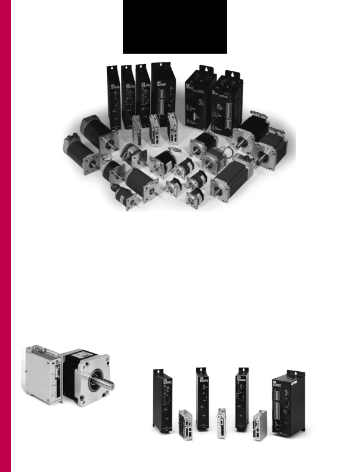
Pacific Scientific Steppers cover
a broad range of possible motion applications. High-quality, innovative
design is built into rugged, reliable
high-performance motors — from
the small to the very powerful. Add
a Pacific Scientific indexer or drive
for the pinnacle in stepper system performance.
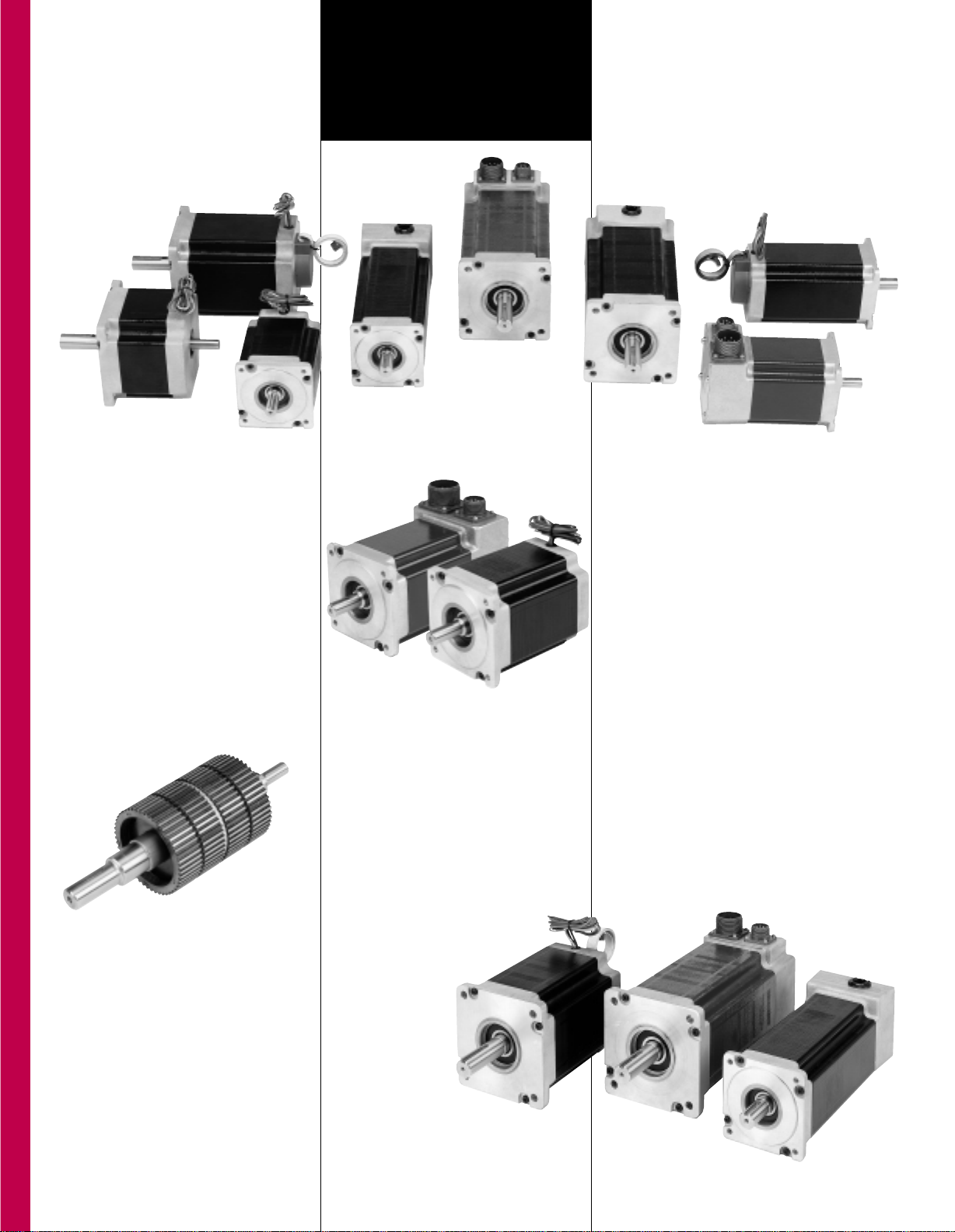
POWERPAC
POWERPAC hybrid step motors offer
the highest torque-per-frame size of
any motor in the industry.
steppers are noted for their ruggedness and reliability.
POWERMAX II
POWERMAX II sets the performance
standard for NEMA 23 step motors.
With up to 253 oz-in. of holding
torque, you won’t find a more powerful two-inch stepper.
We can build POWERMAX II to your
specifications, in the volumes you
need, according to your JIT or other
delivery schedule.
Conventional Hybrid Step Motors
These high-efficiency, low loss hybrid
step motors are available in conventional
round-frame configurations.
Our general-purpose hybrid steppers
allow you to tailor a motor to your
in-plant or OEM specification.
Pacific Scientific Stepper
Drives and Indexers Complete
the Package
From the modular, flexible 6410
drive module through the fully-programmable powerful motion control of
the 5645 indexer/drive, Pacific
Scientific stepper drives offer highperformance features with exactly the
functionality you need. Ask for more
information on the Pac Sci line of
stepper drive products today.
Available in NEMA 34 and 42 frames,
these motors offer holding torques
to a staggering 5700 oz-in. Like all
Pacific Scientific motors, POWERPAC
1
TABLE OF
CONTENTS
Selection Overview
2
Hybrid Step Motor Technology
5
Application Assistance
6
POWERPAC Hybrid Step Motors-NEMA 34 & 42
10
• Sigmax
®
technology
• Standard Hybrid
POWERMAX II Hybrid Step Motors-NEMA 23
38
• Sigmax
®
technology
• Standard hybrid
• Sigmax Technology, low inertia rotor
• Standard hybrid, low inertia rotor
General Purpose Conventional Hybrids-NEMA 23, 34, & 42
54
• Sigmax technology
• Standard hybrid
Special Purpose Hybrid Step Motors-NEMA 23
73
• Sigmax
®
technology,low inertia rotor
• Standard hybrid, low inertia rotor
POWERSYNC AC Synchronous Motors-NEMA 34 & 42
82
P
acific Scientific
maintains a
worldwide network of support
resources to better serve our
customers as a global supplier of
motion control technology.
We are dedicated to quality in every
component manufactured. We are
committed to providing exceptional
customer service, unparalleled
product quality and reliable delivery
with short lead times. Techniques
such as data networking and
Benchmarking support our
commitment to quality and the
continuous improvement of
operations and products.
Our complete selection of high
performance components makes us a
single source of supply in many
motion control applications.
• brushless servo motors and drives
• adjustable speed motors and drives
• hybrid stepper motors and drives
• multi-axis programming software
• permanent magnet DC motors
• brushless servo motors
• low inertia servo motors
• hybrid stepper motors
• AC synchronous motors
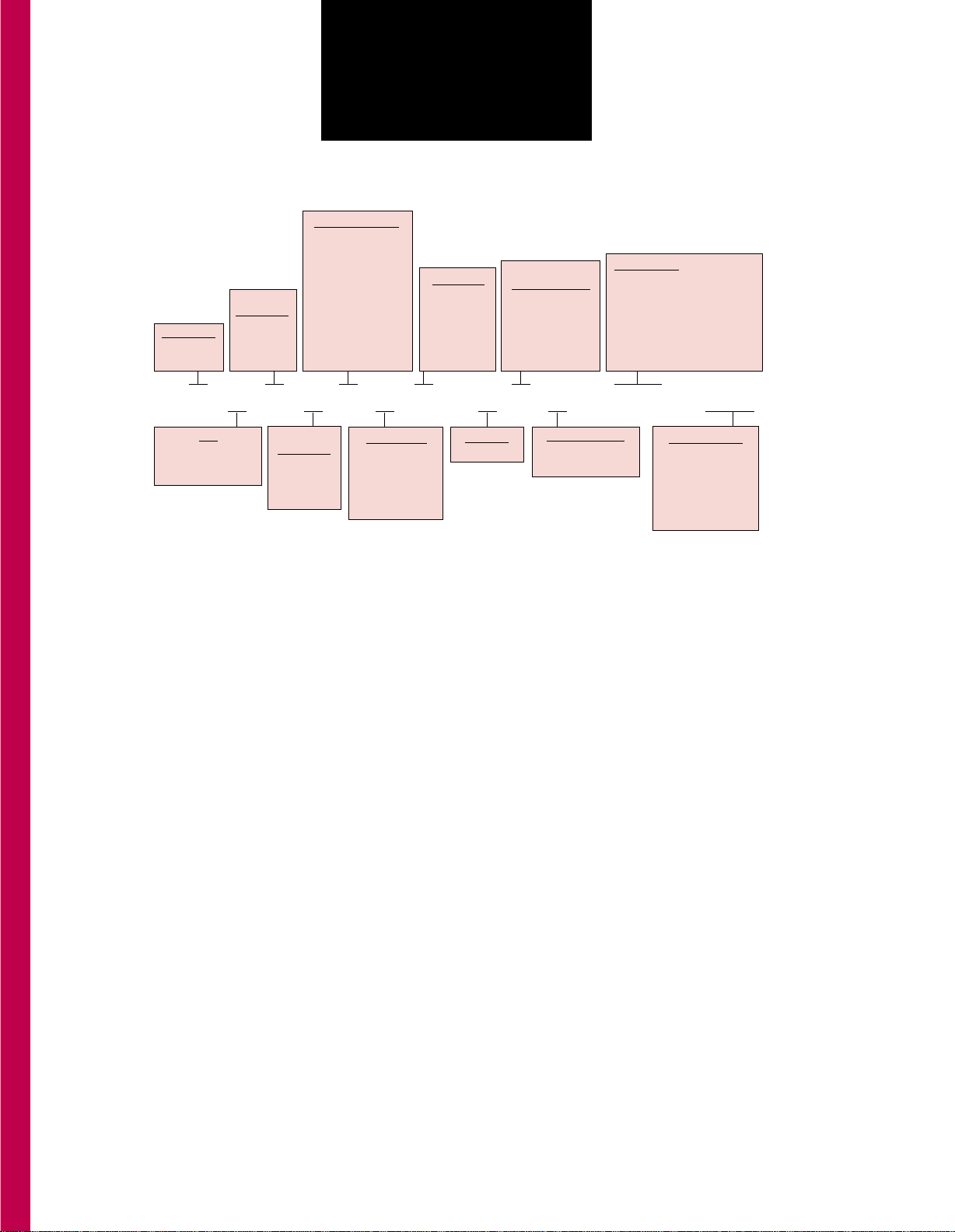
2
SELECTION
OVERVIEW
GENERAL PURPOSE MOTORS
POWERPAC™ HYBRIDS—
K Series – Sigmax®technology
N Series – standard hybrid
POWERMAX II®HYBRIDS
M Series—Sigmax®technology
P Series—standard hybrid
M “J” Series—Sigmax®technology—low inertia rotor
P “J”Series—standard hybrid—low inertia rotor
CONVENTIONAL HYBRIDS
E Series—Sigmax®technology
H Series—standard hybrid
SPECIAL PURPOSE HYBRIDS
E “J” Series—Sigmax®technology—low inertia rotor
H “J”Series—standard hybrid—low inertia rotor
POWERSYNC™ AC SYNCHRONOUS
MOTORS
SN Series—Synchronous motors
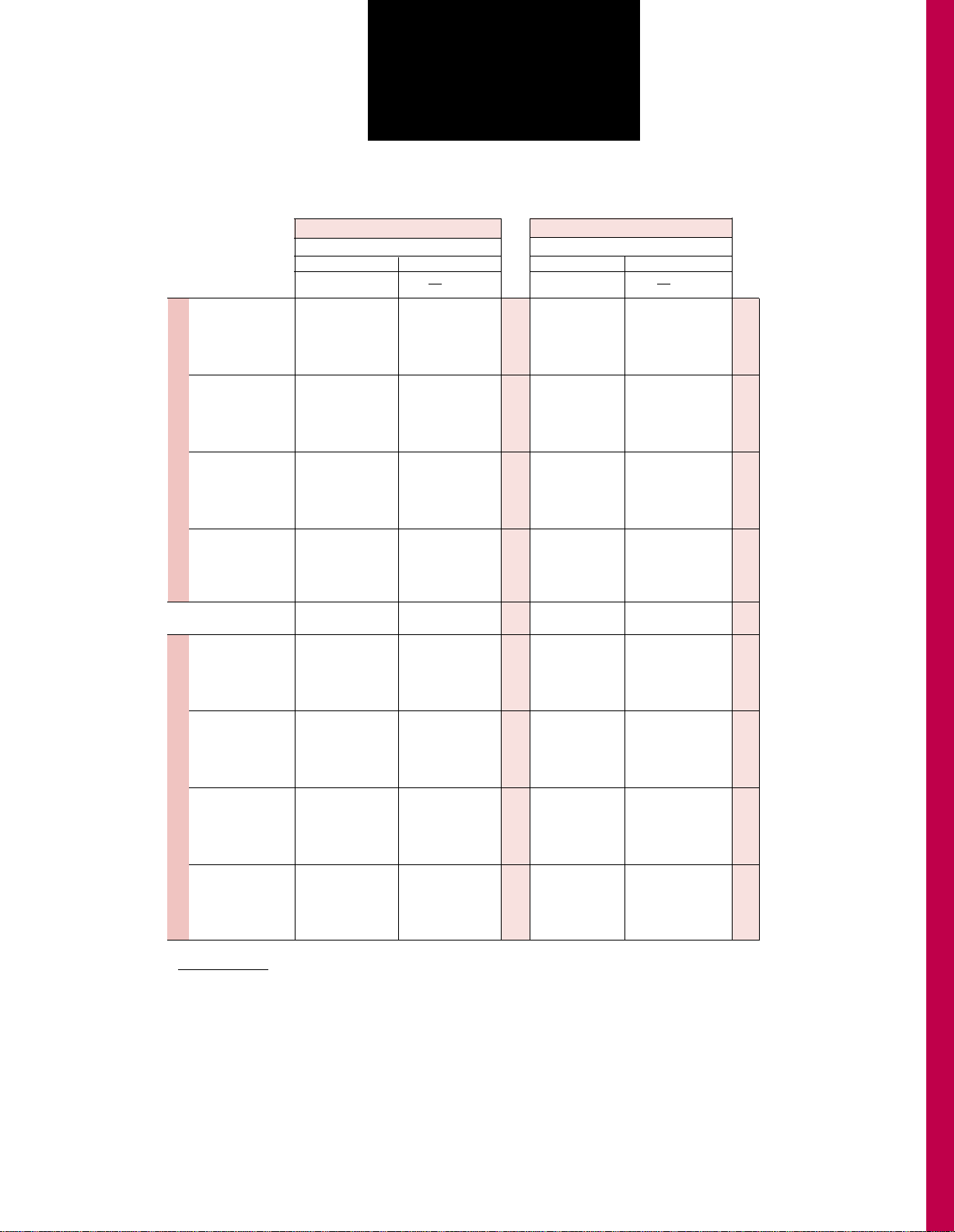
Step Motors
NEMA 23 Frame NEMA 34 Frame NEMA 42 Frame
2.3 3.4 4.2
Holding T orque Range (oz-in./Nm)
570-2790 oz-in. 1480-5700 oz-in.
(4.02-19.69 Nm) (10.45-40.23 Nm)
450-2180 oz-in. 1150-4365 oz-in.
(3.18-15.39 Nm) (8.12-30.81 Nm)
89-253 oz-in.
(.63-1.79 Nm)
42-214 oz-in.
(.29-1.51 Nm)
99-252 oz-in.
(.70-1.78 Nm)
79-201 oz-in.
(.55-1.42 Nm)
85-225 oz-in. 223-1300 oz-in. 957-3958 oz-in.
(.60-1.59 Nm) (1.58-9.18 Nm) (6.76-27.95 Nm)
36-156 oz.in. 158-916 oz-in. 585-2833 oz-in.
(.25-1.10 Nm) (1.12-6.47 Nm) (4.13-20.00 Nm)
77-196 oz-in.
(.54-1.39 Nm)
54-141 oz-in.
(.38-.99 Nm)
Maximum pull-out Maximum pull-out
torque to 900 oz-in. torque to 1550 oz-in.
(6.36 Nm) at 72 RPM (10.95 Nm) at 72 RPM
15
15
38
46
45
48
48
54
58
58
73
75
75
82
86

3
TECHNICAL OVERVIEW
(Con’t)
TYPES
POWERPAC K Series . . . . . . . . . . . . . . . . . . . . . . . . . . . . . . .Sigmax
®
hybrid construction
POWERPAC N Series . . . . . . . . . . . . . . . . . . . . . . . . . . . . . . .Standard hybrid construction
POWERMAX II M Series . . . . . . . . . . . . . . . . . . . . . . . . . . . . .Sigmax hybrid construction
POWERMAX II P Series . . . . . . . . . . . . . . . . . . . . . . . . . . . . .Standard hybrid construction
General Purpose Conventional hybrid E Series . . . . . . . . . . . .Sigmax hybrid construction
General Purpose Conventional hybrid H Series . . . . . . . . . . . .Standard hybrid construction
ROTOR CONSTRUCTION
POWERPAC N and K Series;
POWERSYNC AC Synchronous Motors . . . . . . . . . . . . . . . . .Laminated
POWERMAX II M and P Series;
Conventional E and H Series with “L” rotor designates . . . . . . . Laminated
(high speed efficiency)
POWERMAX II M and P Series;
Special purpose E and H Series with “J” rotor designates . . . . . Low mass/low inertia (fast start/stop,
high acceleration)
WINDINGS
H, J, K, L, M and N . . . . . . . . . . . . . . . . . . . . . . . . . . . . . . . . . Standard winding designations
T type . . . . . . . . . . . . . . . . . . . . . . . . . . . . . . . . . . . . . . . . . . . Maximum torque at low speed
P type . . . . . . . . . . . . . . . . . . . . . . . . . . . . . . . . . . . . . . . . . . . Maximum torque at high speed
A, B, C, D, E, F, G . . . . . . . . . . . . . . . . . . . . . . . . . . . . . . . . . . Additional standard windings
PHASES . . . . . . . . . . . . . . . . . . . . . . . . . . . . . . . . . . . . . . . . . . . . . . . . . 2
FULL STEPS PER REVOLUTION . . . . . . . . . . . . . . . . . . . . . . . . . . . . . . 200
FULL STEP ANGLE . . . . . . . . . . . . . . . . . . . . . . . . . . . . . . . . . . . . . . . . 1.8°
ANGULAR ACCURACY
POWERPAC N Series . . . . . . . . . . . . . . . . . . . . . . . . . . . . . . . ±3% of one full step, no load
non-cumulative
POWERPAC K Series . . . . . . . . . . . . . . . . . . . . . . . . . . . . . . . ±1.5% of one full step, no load
non-cumulative
POWERMAX II M and M “J”;
E and E “J” Series . . . . . . . . . . . . . . . . . . . . . . . . . . . . . . . . . . ±1.5% of one full step, no load,
non-cumulative
POWERMAX II P and P “J”;
H and H “J”, H Series . . . . . . . . . . . . . . . . . . . . . . . . . . . . . . . . ±3% of one full step, no load,
non-cumulative
OPERA TING TEMPERA TURE . . . . . . . . . . . . . . . . . . . . . . . . . . . . . . . . -20 to 40°C
INSULATION . . . . . . . . . . . . . . . . . . . . . . . . . . . . . . . . . . . . . . . . . . . . . NEMA Class B, 130°C
AGENCY APPROVAL . . . . . . . . . . . . . . . . . . . . . . . . . . . . . . . . . . . . . . . All NEMA 34 and 42 frame motors are
UL recognized; Class B motor
insulation (File E103510)
Construction (File E61960)
CE marked per EN60034-1
INSULATION RESISTANCE . . . . . . . . . . . . . . . . . . . . . . . . . . . . . . . . . . 100 Megohms @500V dc and 25°C
www.pacsci.com

TECHNICAL OVERVIEW
(CON’T)
4
SEALING . . . . . . . . . . . . . . . . . . . . . . . . . . . . . . . . . . . . . . . . . . . . . . . .POWERPAC N and K Series and Nema 34
and 42 with a “C”, “L” or “M” designation in
the model number have washdown
construction in accordance with NEMA MG1-
1.26, part E. With the addition of a shaft seal,
they meet IEC (International Electrotechnical
Commission) IP65 and are suitable for
washdown requirements.
ENCODER OPTIONS
POWERPAC . . . . . . . . . . . . . . . . . . . . . . . . . . . . . . . . . . . . . . . .See page 36
POWERMAX II . . . . . . . . . . . . . . . . . . . . . . . . . . . . . . . . . . . . . .See page 53
Conventional & Special Purpose Hybrids . . . . . . . . . . . . . . . . . . .See page 79-80
POWERSYNC . . . . . . . . . . . . . . . . . . . . . . . . . . . . . . . . . . . . . .See page 93
www.pacsci.com
HYBRID STEP MOTOR
TECHNOLOGY
GENERAL PURPOSE MOTORS
These motors offer torque, speed and acceleration
characteristics to fulfill commonly encountered applications.
All general purpose motors are available in both standard
and Sigmax
®
configurations.
This category includes:
• M and P Series POWERMAX II
®
hybrid motors, the
economical and high performance alternative to
conventional NEMA 23 step motors
• H and E Series conventional (round frame) hybrid motors
in a full range of frame sizes, with a broad selection of
windings to duplicate or exceed the performance of most
existing step motors
HIGH TORQUE
The POWERPAC N and K Series, in both NEMA34 and 42
frames, provide an impressive range of high torque output.
See the Ratings and Characteristics for the NEMA 34 frame
starting on page 15, followed by torque and acceleration
(torque to inertia ratio), and torque linearity comparisons.
Performance curves start on page 18. NEMA 42 information
starts on page 24.
HIGH ACCELERATION
Both the POWERPAC N and K Series have high torque-toinertia ratios that provide high acceleration rates to move loads
fast. The K Series, which incorporates the flux-focusing Sigmax
®
technology, provides the highest acceleration rates. Specify the
K Series for the most rapid load positioning. See the Ratings
and Characteristics for the NEMA 34 frame starting on page 15,
followed by torque and acceleration (torque-to-inertia ratio), and
torque linearity comparisons. Performance curves start on page
19. NEMA 42 information starts on page 24.
Patented Sigmax®technology*
redirects magnetic flux to inhibit
leakage and optimize torque production.
* Sigmax®technology is covered by U.S. patents
4,712,028, 4,713,470, 4,763,034 and 4,827,164.
SPECIAL PURPOSE MOTORS
Now and then, you’ll run into an application with special acceleration
requirements. With PacSci special purpose motors, you may not
need to order a customized motor or compromise performance.
All are offered in conventional (round frame) configurations:
• E “J” and H “J” Series motors, in NEMA 23 frame sizes, with
hollow, low mass rotors for rapid acceleration
Still don’t see it here? Just call. Or fax an application data form
(pages 8 and 9) to your Pacific Scientific distributor or the factory.
We have an extensive customization capability.
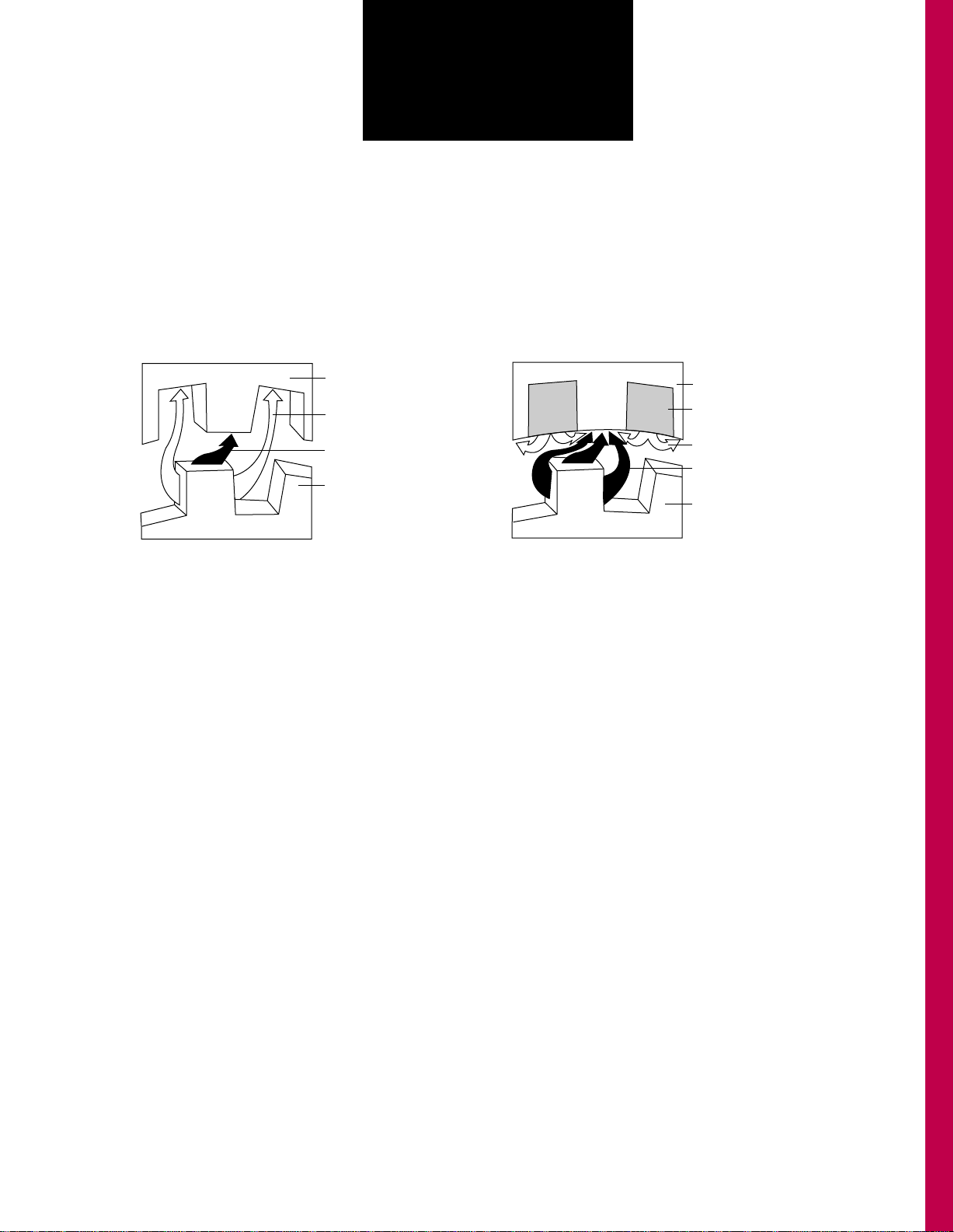
SIGMAX®TECHNOLOGY
SIGMAX
®
AND STANDARD
HYBRID STEP MOTORS
Here’s how Sigmax works.
• Stator mounted rare earth magnets concentrate
magnetic flux at desired points between the rotor and
stator
• Flux focusing action optimizes flux paths
• Produces higher torque and current utilization is better
than a comparably sized standard hybrid
Typical paths of flux transfer
in an energized conventional
hybrid step motor.Some flux
leakage occurs in normal
operation.
STANDARD HYBRID
S
N
Stator
Non-torque
producing flux
Torque producing
flux
Rotor
Stator
Rare earth magnet
inserts
Focusing flux
Concentrated torque
producing flux
Rotor
5
www.pacsci.com
S
N
S
S
N
N
www.pacsci.com
6
APPLICATION
ASSISTANCE
HOLDING TORQUE
Holding torque and rated current are leading
specifications for selection in the Ratings and
Characteristics tables for all motors. Holding torque is
often used as a figure of merit when comparing
motors. It specifies the maximum external torque that
can be applied to a stopped motor with rated current
applied without causing the motor to rotate
continuously.
Pacific Scientific hybrid step motors are used with
a variety of drivers from many different
manufacturers. These drivers have an extremely
broad range of voltage and current ratings. It is not
practical to show individual torque-speed curve
performance given the extensive combinations of
driver voltages and currents. Instead, holding torque
is shown for reference along with rated current.
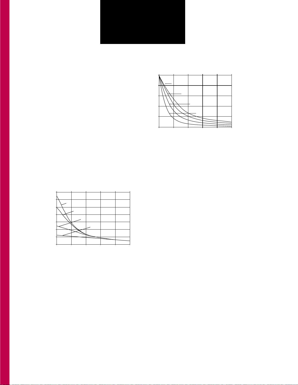
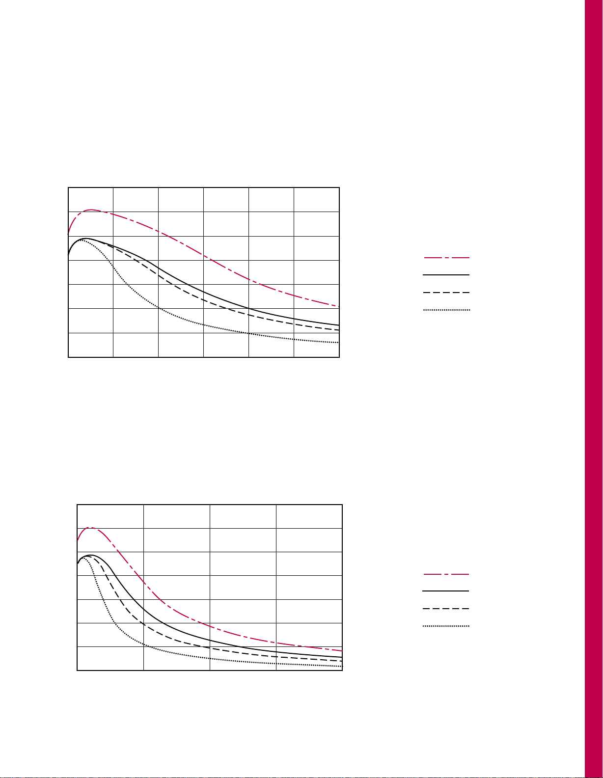
TORQUE-SPEED CURVES
As applied voltage and/or current to the motor is
changed, motor performance is altered. Figures 1
and 2 show typical torque-speed curves using a
bipolar chopper driver.
CURRENT CHANGES
VS. PERFORMANCE
Figure 1 shows the performance of the same motor
driven by bipolar chopper drivers with different
current ratings. All drivers have the same supply
voltage. Note that high speed performance is not
appreciably affected by the different current ratings.
Low speed running torque, however, varies
considerably with changes in the current rating. It is
important to understand that when current over the
rated current of the motor is applied, the increase in
torque will not be proportional to the increased
current. Furthermore, applied current levels
increasingly higher than rated current will likely result
in damage to the motor from demagnetization and/or
overheating.
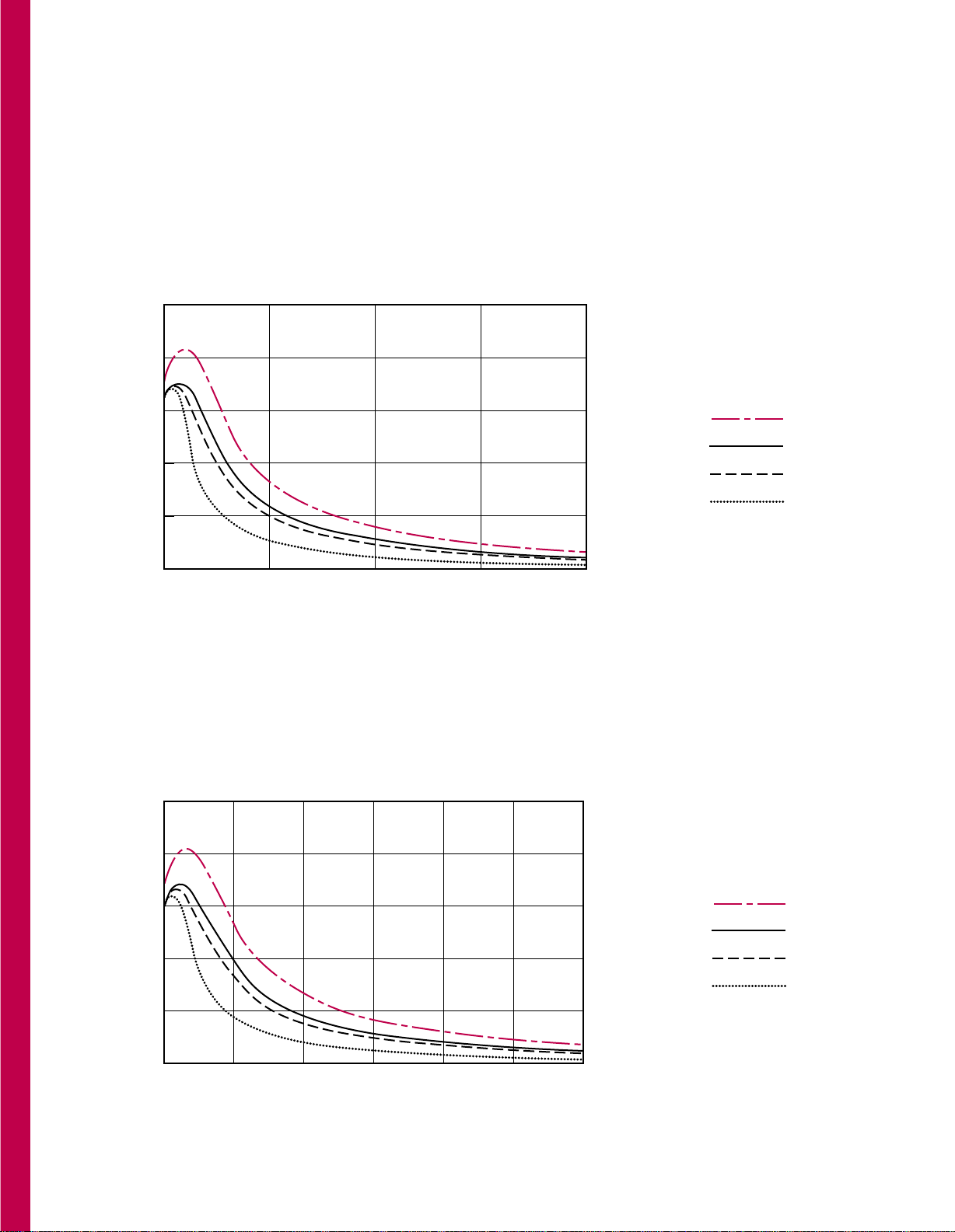
VOLTAGE CHANGES
VS. PERFORMANCE
Figure 2 shows the performance of the same motor
driven by bipolar chopper drivers with different
supply voltage ratings. All drivers have the same
current rating. Note that low speed running torque is
high and not appreciably affected by supply voltage
differences. High speed performance, however,
varies considerably with changes in supply voltage.
Caution must be exercised when increasing supply
voltage. Higher voltages will result in increased motor
heating regardless of motor speed.
APPLICATION ENGINEERING
Need help with your motor selection? We make it
simple and economical to apply step motors in your
designs. Application engineering assistance is only a
phone call or FAX away from your Pacific Scientific
distributor or the factory. To assist us in providing the
optimum motor for your application, please copy and
complete the STEP MOTOR APPLICATION DATA
form on pages 8 and 9. FAX it to our Application
Engineering Department at (815) 226-3148 and we
will provide a prompt reply.
Our response includes a comprehensive torquespeed performance curve of the recommended motor
at your voltage and current levels.
CUSTOM MOTORS
Even though we offer a broad spectrum of standard
motors, we recognize that you might need something
special. We routinely design custom windings to
provide the application specific characteristics you
need. Atypical modification such as a special shaft is
also a part of this service. Don’t hesitate to call us
and follow up with the application data form
described above.
1.0
0.8
0.6
0.4
0.2
0.0
0
0
600
2000
1200
4000
1800
6000
2400
8000
3000
10000
SPEED (FULL STEP/SEC)
SPEED (RPM)
NORMALIZED TORQUE (UNITLESS)
4 x V
3 x V
2 x V
1 x V (Reference curve)
Figure 2
1.4
0.0
0
0
600
2000
1200
4000
1800
6000
2400
8000
3000
10000
SPEED (FULL STEP/SEC)
SPEED (RPM)
NORMALIZED TORQUE (UNITLESS)
1.5 x Rated I
Figure 1
1.2
1.0
0.8
0.6
0.4
0.2
1.0 x Rated I (Reference curve)
.5 x Rated I
.25 x Rated I
www.pacsci.com
7
APPLICATION
ASSISTANCE
For a comprehensive analysis of your requirements,
just complete and FAX us the STEP MOTOR
APPLICATION DATA form on pages 8 and 9 (See
APPLICATION ASSISTANCE, previous page). An
application engineer will contact you promptly.
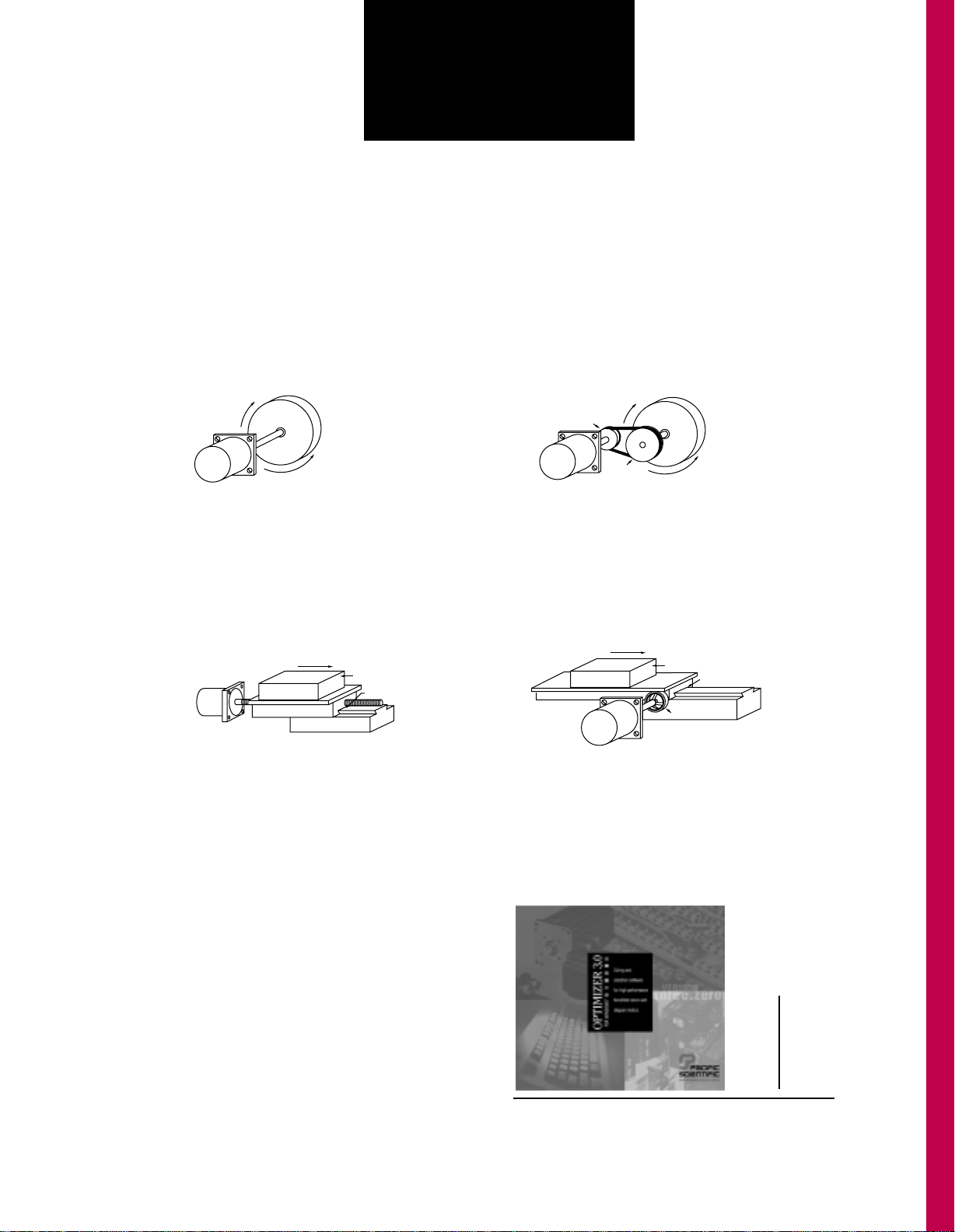
ROTARY MOTION—DIRECT DRIVE
Enhanced hybrid motor torque production, utilizing
Sigmax®technology, is ideal for direct drive applications. Benefits include elimination of mechanical
gear reduction. Be sure to use a flexible coupling.
LINEAR MOTION—LEADSCREW DRIVE
ROTARY MOTION—BELT DRIVE
Timing belt or band driven rotary motion is simple to
control, efficient and relatively free from backlash.
TANGENTIAL MOTION—DIRECT DRIVE
Step motors are well suited to table drives because
load remains constant. Leadscrew, rack and pinion,
or tangential systems can achieve the desired linear
motion and accuracy needed for many applications.
Ask us about Optimizer 3.0™ for Windows,™ our menu
driven sizing and selection software package. You’ll find
out how easy it can be to optimize your motor selection.
Request your free copy of Optimizer 3.0 in Windows™
compatible format on CD-ROM. Inquire at www.pacsci.com
Rotation
Load
Torque
Direction
Static
Force
Friction
Coefficient
LOAD
Rotation
Load
Torque
Driven
Pulley
Motor Pulley
Direction
Static
Force
Friction
Coefficient
LOAD
Motor
Tangential
Drive
VERSION
3.0
Tangential drives make use of the step motors high
torque-to-inertia ratios. In high speed tape and printhead drives, enhanced hybrid motors provide rapid
bidirectional accel/decel and critical position control.
SIZING/SELECTION SOFTWARE

www.pacsci.com
8
STEP MOTOR
APPLICATION DATA
FAX to 815-226-3148
Pacific Scientific
Application Engineering Dept.
Company
Date _
Address
City
State Zip
Name Title Phone
Product Description
GENERAL
• APPLICATION DIAGRAM Draw below or fax
separately. Indicate key power transmission
details, e.g., pulley and gear ratios, lead screw pitch,
efficiencies, nut preload, etc.,. . .all this to size motor
and/or control properly.
• TYPICAL LOAD VELOCITY PROFILE Using the
diagram below as a guide, complete the values for
V through T
4
. Show worst case for proper sizing.
• PRODUCTS CURRENTLY USED List manufacturer
and model number
V = Velocity =
T1= Accel =
T2= Run =
T3= Decel =
T4= Dwell =
DRIVE INFORMATION
Bus Voltage_________ Phase Current_________
■■ Not Specified Yet
■■ Bipolar
■■ Unipolar
STATIC REQUIREMENTS
■■ Accuracy - Accurate to within ______________.
■■ Repeatability - Resolution = ______________.
■■ Holding Torque required = ____________oz in.
SYSTEM LOADING
■■ Friction loading _____________oz in.
■■ Total Load Inertia _________________oz in s
2
(include coupling and all power transmission inertias)
■■ Axial Load: Inward Load = ____________lb.
Outward Load = ___________lb.
■■ Radial Load _______________________lb.
COUPLING ■■ solid ■■ flex ■■ bellows
ELECTRICAL CHARACTERISTICS/FEEDBACK
■■ Inductance = ______ ■■ Number of Leads_____
■■ Resistance/phase = _________________ Ω
ENCODER
■■ Encoder Line Count =________ ppr
■■ Line Driver ■■ Non-Line Driver
ENVIRONMENT
■■ Ambient Temp. _____________ °Celcius
■■ Splashproof (IP65)
TIME
V
VELOCITY
NEXT CYCLE
T1 T2 T3 T4

www.pacsci.com
9
STEP MOTOR
APPLICATION DATA
(CON’T)
• STANDARD AND SPECIAL FEATURES
Motor model number from catalog
Circle whether you want standard or special features. If
special, indicate details. Note that special features may
result in increased price or leadtime.
• FRONT SHAFT (standard) (special)
D shaft length
±
(±.015)*
C shaft dia. ±
(+.0000/-.0005)*
run out
(.002 std. ext.)*
— Straight Key per electric motor standards
(standard option) (special)
Key: width height
length Other
Company Date
MOTOR
circle or specify
Note: All motors are 1.8°, 2 Phase.
• REAR END BELL (standard) (special)
mtg. hole B.C. ± (±.010)*
mtg. holes
hole pattern
other
• REAR SHAFT (standard) (special)
shaft length
±
(±.040)*
shaft dia.
±
(+.0000/-.0005)*
run out
(.002)*
other
— Flat See Fig. 1 (standard option) (special)
Min. usable length X
Dim. over flat Y ± (±.005)*
Corner radius R allowed
(±.060)*
Other
— Woodruff Key See Fig. 2
(standard option) (special)
ANSI std. key no.
(Example 303)
Key location Z
±
(±.020)*
Other
B - Pilot Diameter
A - Flange Width
E - Max Motor Length
F - Pilot Depth
.003 A
.002
-A-
.003 A
0,077
0,051
0,077
1
A
B
C
D
F
E
MOTOR LEADS
FIGURE 1
X
R
Y
FIGURE 2
Z
NOTES:
NEMA standard for shaft run out is .002" + .001"
for each additional inch of extension past the
standard length.
www.pacsci.com
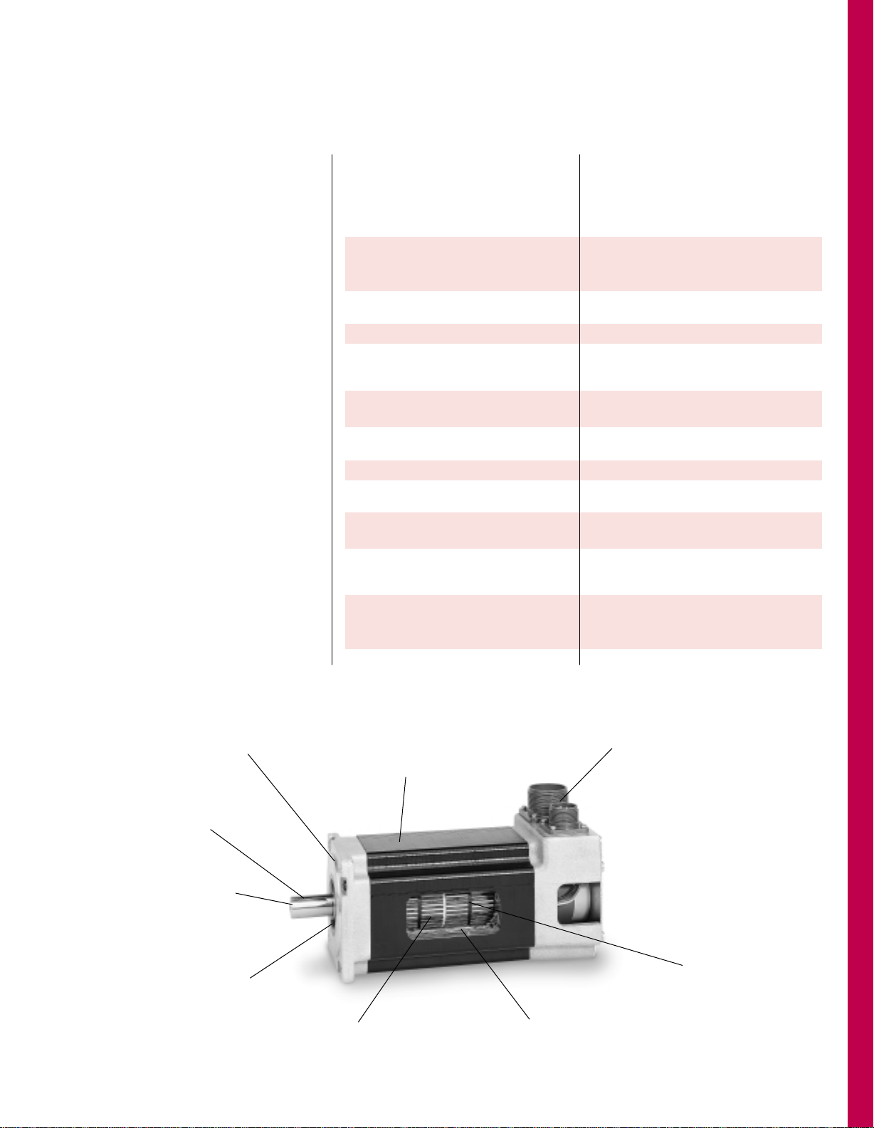
POWERPAC
™
HYBRID STEP MOTORS
Holding Torques to 5700
oz-in. (356 lb-in.)
New POWERPAC rugged NEMA 34 and
42 frame hybrid steppers provide the
highest torques per frame size in the
industry. Optimal magnetics in a
“housingless” frame combine with a
large diameter rotor and new rotor/
stator design to produce more torque
and provide high acceleration
capabilities. This unique design also
features low detent torque for
smoother microstepping. In addition,
POWERPAC runs cooler than
comparable size steppers.
N and K Series
POWERPAC is available in two
different designs; the N and K Series.
Both provide exceptionally high
holding torques. In addition, both
have high torque-to-inertia ratios and
therefore high acceleration
capabilities. The K Series incorporates
our patented Sigmax®flux focusing
technology and provides 25% more
torque than the N Series plus even
higher acceleration performance!
POWERPAC hybrid steppers
meet demanding motion
requirements, making
them cost effective
alternatives to
servo motors
in applications
with moderate
speed requirements.
Options
Combinations of standard options are
routinely provided to customize the
motor for your specific requirements.
For termination, select from terminal
board connections (via conduit sealed construction), MS connectors
(sealed construction) or flying leads.
Rear shaft extensions include one with
end bell mounting provisions for a
user installed encoder. Factory
mounted encoders are installed inside
the rear end bell in a sealed
construction...or outside, mounted
to the rear end bell. Front shaft
modifications may be specified. A
configuration such as an integral
spline is furnished as a special option.
Bipolar or unipolar phase sequencing
is readily available. In addition to
the standard selection of windings,
special windings are also provided.
Just call us!
10
www.pacsci.com
Sizing and Selection
Our OPTIMIZER™ Version 3.0
for Windows is a powerful motor
sizing and selection software program.
It provides a simple, time saving
method to specify the best POWERPAC
motor for your specific requirements.
Contact your Pacific Scientific
distributor for a copy or visit us
on the web at www.pacsci.com
BENEFITSFEATURES
With holding torques to 5700 oz-in. (356 lb-in.), Optimized magnetics provide maximum
the N and K Series provide the highest torques performance in small envelope, reducing space
per frame size in the industry— more than 3 required for the motor.
and 5 phase designs.
Improved torque linearity (above rated current) Acceleration boost to move loads even faster.
provides high peak torque capability Provides more torque for intermittent duty applications
(duty cycle dependent, contact factory)
High torque at moderate speeds Cost effective alternative to servo motors
Low detent torque harmonic Provides smoother microstepping performance
K Series uses patented Sigmax
®
technology Select from broad performance
to develop 25% more torque than N Series range to meet your requirement
Runs cooler than comparable steppers Longer, more reliable motor life— backed by a
using identical drive parameters two year warranty
Special rotor design for high acceleration Move/position loads fast
Rugged “housingless” square frame Efficient use of volume for optimal magnetic circuit
Sealed per IP65 For splashproof requirements
Outer bearing races won’t turn—front locked Long life bearings— also prevents
(in steel insert) and rear held by O-ring axial shaft movement for encoder applications
Extensive selection of shaft configurations, Match your requirements
terminations, standard and special windings
Two phase design Compatible with most drivers, smoother microstepping,
and lower input power required vs. three phase for
same torque
Optional encoder mounting provisions Optimizes control scheme
MORE POWER IN A SMALLER PACKAGE - POWERPAC
Optional shaft sizes and
special designs (spline, for
example) available
MS connector termination for motor and
optical encoder. Flying leads and terminal
board via conduit termination also
standard
Large diameter rotor coupled with optimum
magnetic design produces highest torque
and acceleration - both N and K Series
Rugged, square frame housingless
design provides NEMA and IP65
splashproof construction
Rare earth rotor magnets
provide high demagnetization
resistance
Standard NEMA mounting
Straight key. Other
options available
Long life bearings
withstand high radial
and axial forces
Sigmax®technology in K Series adds flux
concentrating rare earth stator magnets for even
higher torque and acceleration than N series
11
www.pacsci.com
12
POWERPAC
™
HYBRIDS INDEX
Product Overview
Inside front cover
How to use this Section
12
Features
11
Selection Overview
13
Technical Overview
3-4
Hybrid Step Motor Technology
5
Application Assistance
6-9
NEMA 34 Frame Motors
Model Number Code 14
Ratings and Characteristics 15-18
Torque and Acceleration Comparisons 19
Torque Linearity Curves 20
Performance (Torque/Speed) Curves 21-22
Drawings 23-24
NEMA 42 Frame Motors
Model Number Code 25
Ratings and Characteristics 26-28
Torque and Acceleration Comparisons 19, 29
Torque Linearity Curves 29
Performance (Torque/Speed) Curves 30-31
Drawings 32-33
Motor Technical Data
Power Connections 34-35
Phase Sequencing Tables 36
Encoder Mounting Options 36
Shaft Loading 37
Bearing Fatigue Life 37
How to use
this section
This guide covers the technical
information required to select and
order POWERPAC hybrid step
motors. Select the proper motor
using one of the following
procedures.
• If you’re already familiar with
these motors and the available
options, refer to the Model Number
Codes on pages 14 (NEMA 34)
and 25 (NEMA 42) to verify coded
information prior to ordering.
• If you’re not familiar with these
motors and the available options:
- refer to the Selection Overview,
p. 13, and Technical Overview,
p. 3-4. Ratings and Characteristics
for the NEMA 34 frame start on
p. 15 and p. 26 for the NEMA 42
frame. Both are followed by torque
and acceleration comparisons,
torque/speed curves and drawings
as shown in the index at the right.
Technical data common to both
NEMA 34 and 42 frames, including
connections, phasing diagrams,
encoder options, shaft loading
and bearing fatigue life starts on
page 34. To order, construct a
Model Number (pp. 14 and 25)
after all the technical parameters,
including options, are determined.
- If Application Assistance is
required, see the section starting
on page 6.
- Use OPTIMIZER
®
Version 3.0, our
Windows™compatible sizing and
selection software for both hybrid
steppers and brushless servomotors.
Optimizer will select a motor,
however, it may not include all
the options required. Construct
a model number after all the
technical parameters, including
options, are determined. Call
or fax us for your free disk
or visit us at www.pacsci.com
www.pacsci.com
13
POWERPAC™HYBRIDS
SELECTION OVERVIEW
1 stack
2 stacks
3 stacks
4 stacks
1 stack
2 stacks
3 stacks
4 stacks
* Holding T
or
que
...a figure of merit for acceleration capability
Rotor Inertia
K Series - Sigmax
®
flux focusing technology
N Series - Standard
POWERPAC™ HYBRIDS
s
2
s
2
Page
Page
NEMA 34 NEMA 42
(3.38" square frame) (4.325" square frame)
Holding torque Torque-to-inertia ratio* Holding torque Torque-to-inertia ratio*
oz-in. (Nm)
rad
x 10
-3
oz-in. (Nm)
rad
x 10
-3
845(5.96) 41.8 15 2135(15.07) 27.3 26
1580(11.15) 41.6 16 4025(28.41) 26.0 27
2340(16.52) 41.3 17 5700(40.23) 24.9 28
2790(19.69) 37.2 18 NA NA
665(4.65) 32.9 15 1655(11.68) 21.1 26
1295(8.79) 32.8 16 3145(22.20) 20.3 27
1845(13.02) 32.5 17 4365(30.81) 19.0 28
2180(15.39) 29.1 18 NA NA
www.pacsci.com
14
POWERPAC™HYBRIDS
NEMA 34 Frame
(3.38" Square)
Basic Series
K=Sigmax
®
N=Standard
N3 3 HCHJ-LEK- M 2 -01
Number of
Rotor Stacks
1=1 Stacks
2=2 Stacks
3=3 Stacks
4=4 Stacks
Winding Type
H, J, K, L, and
M=Standards
M-(n/a on 1
stack)
H-(1 stack only)
S=Special, call
factory
Winding/Leads
F=8 Lead (n/a
C construction)
L=4 Lead series
H=4 Lead parallel
E=6 Lead (n/a
C construction)
Special Sequence
00=Standard motor–
no shaft seal
01=Standard motor
with shaft seal
Other #’s will be
assigned for special
motors
Construction/Hookup
R=Regular/leadwire
C=System
MS connector
L=Splashproof/to
terminal board via
conduit connector: 1/2"
NPSC pipe thread
M=Splashproof/to
terminal board via
conduit connector:
metric PG11 pipe thread
S=Special, call factory
Size
3=NEMA 34 frame size;
3.38" width/height,
square frame
Encoder Option
NS=No feedback
All of the configurations listed below
must use construction C or R and
shaft configuration E:
M2=Encoder mounting provisions
SS=Special, call factory
Shaft Modifications
K=Straight key
S=Special, call factory
Shaft Configuration
(Diameter & Length)
N=Single
D=Double (R or C
construction only)
E=Double ended for
encoder (R or C
construction only)
Rotor Type
L=Laminated
Mounting
Configuration
H=Heavy duty
NEMA
S=Special, call
factory
MODEL NUMBER CODE
HOW TO ORDER
Review the Motor Model Number Code to assure that all options are designated. Call your nearest Pacific
Scientific Motor Products Distributor to place orders and for application assistance. If you need to identify your
Distributor, call the Motor Products Division at (815) 226-3100.
The example model number above indicates a N series standard NEMA 34 frame motor with a three stack
rotor. This motor is equipped with a heavy duty front end bell and shaft, and a sealed system rear end
bell with MS connectors. It also has a bipolar parallel connection, a J winding, a straight keyway, encoder
mounting options and a shaft seal.

www.pacsci.com
15
POWERPAC
HYBRIDS
Also see:
• Torque and Acceleration Comparisons, p. 19
• Torque Linearity Curves, p. 20
• Performance Curves, p. 21-22
NEMA 34 FRAME (3.38" Square)—Ratings and Characteristics
Review the Model Number Code, page 14, to assure that all options are designated. Connections, encoders and
phasing diagrams start on page 34. Motor dimensions start on page 23. In addition to those below, motors with
characteristics for specific performance requirements are offered. Contact factory for more details.
Connection Holding
Torque Phase
Rated Inductance
Current/ Phase Thermal Rotor
Motor (2 phases on) Phase Resistance Detent Resistance Inertia
Model Number oz-in (Nm) (ohms) (mH) Torque oz-in-S2Weight
±10% (amps DC) ±10% Typical oz-in (Nm) (oC/watt) (kgm2x 10-3) lbs (kg)
K31HXHL-LXK-XX-XX • 830(5.86) 8.6 0.18 1.2
K31HXLL-LXK-XX-XX • 830(5.86) 4.3 0.72 4.7
K31HXEL-LXK-XX-XX • 590(4.16) 6.1 0.36 1.2
K31HXHK-LXK-XX-XX • 845(5.96) 6.6 0.29 2.1
K31HXLK-LXK-XX-XX • 845(5.96) 3.3 1.16 8.3
K31HXEK-LXK-XX-XX • 600(4.23) 4.7 0.58 2.1
K31HXHJ-LXK-XX-XX • 820(5.79) 5.5 0.42 2.8
K31HXLJ-LXK-XX-XX • 820(5.79) 2.7 1.69 11.4
K31HXEJ-LXK-XX-XX • 580(4.09) 3.9 0.84 2.8
K31HXHH-LXK-XX-XX • 805(5.68) 2.8 1.55 10.2
K31HXLH-LXK-XX-XX • 805(5.68) 1.4 6.21 40.7
K31HXEH-LXK-XX-XX • 570(4.02) 1.98 3.1 10.2
N31HXHL-LXK-XX-XX • 650(4.59) 8.6 0.18 1.4
N31HXLL-LXK-XX-XX • 650(4.59) 4.3 0.72 5.8
N31HXEL-LXK-XX-XX • 460(3.25) 6.1 0.36 1.4
N31HXHK-LXK-XX-XX • 665(4.69) 6.6 0.29 2.6
N31HXLK-LXK-XX-XX • 665(4.69) 3.3 1.16 10.3
N31HXEK-LXK-XX-XX • 470(3.32) 4.7 0.58 2.6
N31HXHJ-LXK-XX-XX • 645(4.55) 5.5 0.42 3.5
N31HXLJ-LXK-XX-XX • 645(4.55) 2.7 1.69 14
N31HXEJ-LXK-XX-XX • 455(3.21) 3.9 0.84 3.5
N31HXHH-LXK-XX-XX • 635(4.48) 2.8 1.55 12.5
N31HXLH-LXK-XX-XX • 635(4.48) 1.4 6.21 50.1
N31HXEH-LXK-XX-XX • 450(3.18) 1.98 3.1 12.5
Parallel
Series
Unipolar
Rated currents are in
descending order
Torque range:
570-845 oz-in.
35.6-52.8 lb-in.
4.02-5.96 Nm
K Series SIGMAX
®
1 rotor stack
25 2.7 0.0202 5
(0.18) (0.14) (2.27)
Torque range:
450-665 oz-in.
28.1-41.5 lb-in.
3.18-4.69 Nm
N Series Standard
1 rotor stack
18 2.7 0.0202 5
(0.13) (0.14) (2.27)
All ratings typical and at 25°C unless otherwise noted.
An ”X” in the Model Number Code indicates an undefined
option. Colored letter indicates winding. See Model Number
Code on page 14.
Motor connections are determined by the Windings/Leads
designation in the Model Number Code on page 14. Note that
the F designation, although not shown in the above tables, is
an 8-lead option...see Terminations, page 34. In addition to the
lead wire termination, terminal board and MS connector hookup
for parallel, series or unipolar operation is also available.
With rated current applied. Windings at 130°C and motor
unmounted and in still air at 40°C.
Windings at 130°C and motor in still air at 40°C (without heat sink).
Motors may be operated up to 2 times rated current to provide
high peak torque with good torque linearity - duty cycle
dependant, contact factory.
Small signal inductance as measured with impedance bridge at
1kHz, 1 amp.
Thermal resistance measured with motor hanging in still air
(unmounted).
www.pacsci.com
16
Connection Holding
Torque Phase
Rated Inductance
Current/ Phase Thermal Rotor
Motor (2 phases on) Phase Resistance Detent Resistance Inertia
Model Number oz-in (Nm) (ohms) (mH) Torque oz-in-S
2
Weight
±10% (amps DC) ±10% Typical oz-in (Nm) (oC/watt) (kgm2x 10-3) lbs (kg)
K32HXHM-LXK-XX-XX • 1535(10.83) 10 0.18 1.4
K32HXLM-LXK-XX-XX • 1535(10.83) 5 0.7 5.5
K32HXEM-LXK-XX-XX • 1085(7.66) 7.1 0.35 1.4
K32HXHL-LXK-XX-XX • 1515(10.69) 8.1 0.26 2
K32HXLL-LXK-XX-XX • 1515(10.69) 4.1 1.03 8.1
K32HXEL-LXK-XX-XX • 1070(7.55) 5.8 0.52 2
K32HXHK-LXK-XX-XX • 1580(11.15) 6.1 0.45 4
K32HXLK-LXK-XX-XX • 1580(11.15) 3 1.8 16.2
K32HXEK-LXK-XX-XX • 1120(7.90) 4.3 0.9 4
K32HXHJ-LXK-XX-XX • 1510(10.66) 5.1 0.63 5.1
K32HXLJ-LXK-XX-XX • 1510(10.66) 2.5 2.53 20.5
K32HXEJ-LXK-XX-XX • 1065(7.52) 3.5 1.27 5.1
N32HXHM-LXK-XX-XX • 1215(8.58) 10 0.18 1.8
N32HXLM-LXK-XX-XX • 1215(8.58) 5 0.7 7
N32HXEM-LXK-XX-XX • 860(6.07) 7.1 0.35 1.8
N32HXHL-LXK-XX-XX • 1200(8.47) 8.1 0.26 2.6
N32HXLL-LXK-XX-XX • 1200(8.47) 4.1 1.03 10.3
N32HXEL-LXK-XX-XX • 850(6.00) 5.8 0.52 2.6
N32HXHK-LXK-XX-XX • 1245(8.79) 6.1 0.45 5.1
N32HXLK-LXK-XX-XX • 1245(8.79) 3 1.8 20.6
N32HXEK-LXK-XX-XX • 885(6.25) 4.3 0.9 5.1
N32HXHJ-LXK-XX-XX • 1195(8.43) 5.1 0.63 6.5
N32HXLJ-LXK-XX-XX • 1195(8.43) 2.5 2.53 26
N32HXEJ-LXK-XX-XX • 845(5.96) 3.5 1.27 6.5
Parallel
Series
Unipolar
Rated currents are in
descending order
Torque range:
1065-1580 oz-in.
66.5-98.7 lb-in.
7.52-11.15 Nm
K Series SIGMAX
®
2 rotor stacks
50 2 0.038 8.4
(0.35) (0.27) (3.81)
Torque range:
845-1245 oz-in.
52.8-77.8 lb-in.
5.96-8.79 Nm
N Series Standard
2 rotor stacks
36 2 0.038 8.4
(0.25) (0.27) (3.81)
All ratings typical and at 25°C unless otherwise noted.
An ”X” in the Model Number Code indicates an undefined
option. Colored letter indicates winding. See Model Number
Code on page 14.
Motor connections are determined by the Windings/Leads
designation in the Model Number Code on page 14. Note that
the F designation, although not shown in the above tables, is
an 8-lead option...see Terminations, page 34. In addition to the
lead wire termination, terminal board and MS connector hookup
for parallel, series or unipolar operation is also available.
With rated current applied. Windings at 130°C and motor
unmounted and in still air at 40°C.
Windings at 130°C and motor in still air at 40°C (without heat sink).
Motors may be operated up to 2 times rated current to provide
high peak torque with good torque linearity - duty cycle
dependant, contact factory.
Small signal inductance as measured with impedance bridge at
1kHz, 1 amp.
Thermal resistance measured with motor hanging in still air
(unmounted).
POWERPAC
HYBRIDS
Also see:
• Torque and Acceleration Comparisons, p. 19
• Torque Linearity Curves, p. 20
• Performance Curves, p. 21-22
NEMA 34 FRAME (3.38" Square)—Ratings and Characteristics (Con’t)
Review the Model Number Code, page 14, to assure that all options are designated. Connections, encoders and
phasing diagrams start on page 34. Motor dimensions start on page 23. In addition to those below, motors with
characteristics for specific performance requirements are offered. Contact factory for more details.
www.pacsci.com
17
Connection Holding
Torque Phase
Rated Inductance
Current/ Phase Thermal Rotor
Motor (2 phases on) Phase Resistance Detent Resistance Inertia
Model Number oz-in (Nm) (ohms) (mH) Torque oz-in-S
2
Weight
±10% (amps DC) ±10% Typical oz-in (Nm) (oC/watt) (kgm2x 10-3) lbs (kg)
K33HXHM-LXK-XX-XX • 2150(15.17) 9.9 0.22 1.7
K33HXLM-LXK-XX-XX • 2150(15.17) 5 0.87 7
K33HXEM-LXK-XX-XX • 1520(10.73) 7 0.44 1.7
K33HXHL-LXK-XX-XX • 2340(16.52) 9 0.26 2.6
K33HXLL-LXK-XX-XX • 2340(16.52) 4.5 1.06 10.6
K33HXEL-LXK-XX-XX • 1655(11.68) 6.3 0.53 2.6
K33HXHK-LXK-XX-XX • 2205(15.56) 6.1 0.56 5
K33HXLK-LXK-XX-XX • 2205(15.56) 3 2.23 19.9
K33HXEK-LXK-XX-XX • 1560(11.01) 4.3 1.12 5
K33HXHJ-LXK-XX-XX • 2145(15.14) 5 0.83 7
K33HXLJ-LXK-XX-XX • 2145(15.14) 2.5 3.31 27.9
K33HXEJ-LXK-XX-XX • 1515(10.69) 3.5 1.65 7
N33HXHM-LXK-XX-XX • 1715(12.10) 9.9 0.22 2.3
N33HXLM-LXK-XX-XX • 1715(12.10) 5 0.87 9
N33HXEM-LXK-XX-XX • 1215(8.58) 7 0.44 2.3
N33HXHL-LXK-XX-XX • 1845(13.02) 9 0.26 3.4
N33HXLL-LXK-XX-XX • 1845(13.02) 4.5 1.06 13.6
N33HXEL-LXK-XX-XX • 1305(9.21) 6.3 0.53 3.4
N33HXHK-LXK-XX-XX • 1755(12.39) 6.1 0.56 6.4
N33HXLK-LXK-XX-XX • 1755(12.39) 3 2.23 25.8
N33HXEK-LXK-XX-XX • 1240(8.75) 4.3 1.12 6.4
N33HXHJ-LXK-XX-XX • 1710(12.07) 5 0.83 9
N33HXLJ-LXK-XX-XX • 1710(12.07) 2.5 3.31 36
N33HXEJ-LXK-XX-XX • 1210(8.54) 3.5 1.65 9
Parallel
Series
Unipolar
Rated currents are in
descending order
Torque range:
1515-2348 oz-in.
94.7-146.2 lb-in.
10.69-16.52 Nm
K Series SIGMAX
®
3 rotor stacks
75 1.6 0.0567 11.9
(0.53) (0.40) (5.39)
Torque range:
1210-1845 oz-in.
75.6-115.3 lb-in.
8.54-13.02 Nm
N Series Standard
3 rotor stacks
54 1.6 0.0567 11.9
(0.38) (0.40) (5.39)
All ratings typical and at 25°C unless otherwise noted.
An ”X” in the Model Number Code indicates an undefined
option. Colored letter indicates winding. See Model Number
Code on page 14.
Motor connections are determined by the Windings/Leads
designation in the Model Number Code on page 14. Note that
the F designation, although not shown in the above tables, is
an 8-lead option...see Terminations, page 34. In addition to the
lead wire termination, terminal board and MS connector hookup
for parallel, series or unipolar operation is also available.
With rated current applied. Windings at 130°C and motor
unmounted and in still air at 40°C.
Windings at 130°C and motor in still air at 40°C (without heat sink).
Motors may be operated up to 2 times rated current to provide
high peak torque with good torque linearity - duty cycle
dependant, contact factory.
Small signal inductance as measured with impedance bridge at
1kHz, 1 amp.
Thermal resistance measured with motor hanging in still air
(unmounted).
POWERPAC
HYBRIDS
Also see:
• Torque and Acceleration Comparisons, p. 19
• Torque Linearity Curves, p. 20
• Performance Curves, p. 21-22
NEMA 34 FRAME (3.38" Square)—Ratings and Characteristics (Con’t)
Review the Model Number Code, page 14, to assure that all options are designated. Connections, encoders and
phasing diagrams start on page 34. Motor dimensions start on page 23. In addition to those below, motors with
characteristics for specific performance requirements are offered. Contact factory for more details.

www.pacsci.com
18
Connection Holding
Torque Phase
Rated Inductance
Current/ Phase Thermal Rotor
Motor (2 phases on) Phase Resistance Detent Resistance Inertia
Model Number oz-in (Nm) (ohms) (mH) Torque oz-in-S
2
Weight
±10% (amps DC) ±10% Typical oz-in (Nm) (oC/watt) (kgm2x 10-3) lbs (kg)
K34HXHM-LXK-XX-XX • 2725(19.23) 11.3 0.2 2
K34HXLM-LXK-XX-XX • 2725(19.23) 5.6 0.82 8.2
K34HXEM-LXK-XX-XX • 1930(13.62) 8 0.41 2
K34HXHL-LXK-XX-XX • 2790(19.69) 8.7 0.33 3.6
K34HXLL-LXK-XX-XX • 2790(19.69) 4.4 1.32 14.5
K34HXEL-LXK-XX-XX • 1975(13.94) 6.2 0.66 3.6
K34HXHK-LXK-XX-XX • 2580(18.21) 6 0.67 6.3
K34HXLK-LXK-XX-XX • 2580(18.21) 3 2.69 25.1
K34HXEK-LXK-XX-XX • 1825(12.88) 4.3 1.35 6.3
K34HXHJ-LXK-XX-XX • 2770(19.55) 5.5 0.8 8.9
K34HXLJ-LXK-XX-XX • 2770(19.55) 2.8 3.19 35.5
K34HXEJ-LXK-XX-XX • 1960(13.83) 3.9 1.6 8.9
N34HXHM-LXK-XX-XX • 2140(15.10) 11.3 0.2 2.6
N34HXLM-LXK-XX-XX • 2140(15.10) 5.6 0.82 10.6
N34HXEM-LXK-XX-XX • 1510(10.66) 8 0.41 2.6
N34HXHL-LXK-XX-XX • 2180(15.39) 8.7 0.33 4.7
N34HXLL-LXK-XX-XX • 2180(15.39) 4.4 1.32 18.8
N34HXEL-LXK-XX-XX • 1545(10.90) 6.2 0.66 4.7
N34HXHK-LXK-XX-XX • 2035(14.36) 6 0.67 8.1
N34HXLK-LXK-XX-XX • 2035(14.36) 3 2.69 32.4
N34HXEK-LXK-XX-XX • 1440(10.16) 4.3 1.35 8.1
N34HXHJ-LXK-XX-XX • 2170(15.32) 5.5 0.8 11.5
N34HXLJ-LXK-XX-XX • 2170(15.32) 2.8 3.19 45.9
N34HXEJ-LXK-XX-XX • 1535(10.83) 3.9 1.6 11.5
Parallel
Series
Unipolar
Rated currents are in
descending order
Torque range:
1825-2798 oz-in.
114.1-174.4 lb-in.
12.88-19.69 Nm
K Series SIGMAX
®
4 rotor stacks
65 1.3 0.075 15.1
(0.50) (0.53) (6.84)
Torque range:
1940-2180 oz-in.
90.0-136.2 lb-in.
10.16-15.39 Nm
N Series Standard
4 rotor stacks
57 1.3 0.075 15.1
(0.40) (0.53) (6.84)
All ratings typical and at 25°C unless otherwise noted.
An ”X” in the Model Number Code indicates an undefined
option. Colored letter indicates winding. See Model Number
Code on page 14.
Motor connections are determined by the Windings/Leads
designation in the Model Number Code on page 14. Note that
the F designation, although not shown in the above tables, is
an 8-lead option...see Terminations, page 34. In addition to the
lead wire termination, terminal board and MS connector hookup
for parallel, series or unipolar operation is also available.
With rated current applied. Windings at 130°C and motor
unmounted and in still air at 40°C.
Windings at 130°C and motor in still air at 40°C (without heat sink).
Motors may be operated up to 2 times rated current to provide
high peak torque with good torque linearity - duty cycle
dependant, contact factory.
Small signal inductance as measured with impedance bridge at
1kHz, 1 amp.
Thermal resistance measured with motor hanging in still air
(unmounted).
POWERPAC
HYBRIDS
Also see:
• Torque and Acceleration Comparisons, p. 19
• Torque Linearity Curves, p. 20
• Performance Curves, p. 21-22
NEMA 34 FRAME (3.38" Square)—Ratings and Characteristics (Con’t)
Review the Model Number Code, page 14, to assure that all options are designated. Connections, encoders and
phasing diagrams start on page 34. Motor dimensions start on page 23. In addition to those below, motors with
characteristics for specific performance requirements are offered. Contact factory for more details.
www.pacsci.com
19
POWERPAC
HYBRIDS
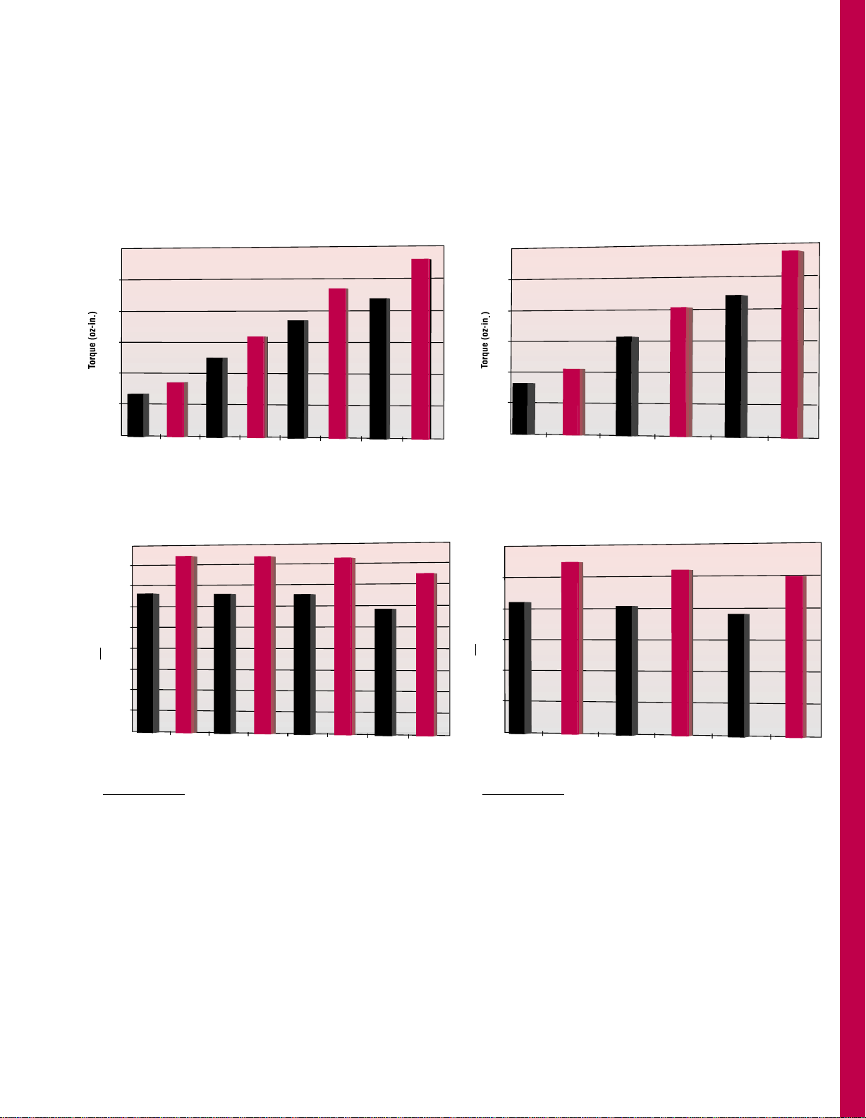
Torque and Acceleration Comparisons
Holding Torque
3000
2500
2000
1500
1000
665
845
1245
1580
1845
2180
2790
2340
500
0
N31
K31
N32
K32
K33
K34
N33
N34
Motor Model/Stack Length
Acceleration
rad
x 10 *
s
2
3
45.0
40.0
35.0
30.0
25.0
20.0
15.0
10.0
5.0
0
N31
32.9
41.8
32.8
41.6
32.5
41.3
29.1
37.2
K31 N32
K32
N33 K33
N34
K34
Motor Model/Stack Length
* Holding Torque
...a figure of merit for acceleration capability
Rotor Inertia
NEMA 34 FRAME (3.38" Square)—
Torque and Acceleration Comparisons
NEMA 42** FRAME (4.325" Square)—
Torque and Acceleration Comparisons
Holding Torque
N41
0
1000
1655
2135
3145
4025
4365
5700
2000
3000
4000
5000
6000
K41
N42
K42
N43
K43
Motor Model/Stack Length
Acceleration
rad
x 10 *
s
2
3
30.0
25.0
20.0
21.1
27.3
20.3
K41N41 K42N42
Motor Model/Stack Length
K43N43
26.0
19.0
24.9
15.0
10.0
5.0
0
* Holding Torque
...a figure of merit for acceleration capability
Rotor Inertia
**Size 42 data shown here for comparison. NEMA 42 starts on
page 25.
www.pacsci.com
20
POWERPAC
HYBRIDS
NEMA 34 FRAME (3.38" Square)—Torque Linearity
A significant POWERPAC performance attribute is that when a current higher than rated current is applied, the increase in torque will be more
linear than other hybrids. Furthermore, current levels increasingly higher than rated current are less likely to cause demagnetization. Capitalize
on this performance characteristic which will provide an acceleration boost to move loads even faster. This technique is applicable to
intermittent duty applications in that the thermal limit of the motor cannot be exceeded. Driving the motor at higher than rated current is duty
cycle dependent. Contact the factory for application assistance.
These curves show the torque at rated current and the torque linearity up to two times rated current.
02.8
4500
5.6 8.4 11.3 14.1 16.9 19.7 22.6
4000
3500
3000
2000
1500
1000
2500
500
31.7
28.2
24.7
21.1
14.1
10.6
7.0
17.6
3.5
0
02.4
4000
4.9 7.4 9.9 12.3 14.8 17.3 19.8
3500
3000
2500
1500
1000
2000
500
28.2
24.7
21.1
17.6
10.6
7.0
14.1
3.5
0
02.5
2500
5 7.5 10 12.5 15 17.5 20
2000
1500
1000
500
17.6
14.1
10.6
7.0
3.5
0
02.1
1400
4.3 6.4 8.6 10.7 12.9 15.1 17.2
1200
1000
800
600
400
200
0
9.8
8.4
7.0
5.6
4.2
2.8
1.4
Holding Torque [Oz-in]
Holding Torque [Oz-in]
Current
[Amps]
Current
[Amps]
Holding Torque [Oz-in]
Current
[Amps]
Holding Torque [Oz-in]
Holding Torque [Nm]
Holding Torque [Nm]
Holding Torque [Nm]
Holding Torque [Nm]
Current
[Amps]
TORQUE LINEARITY
N & K 31 L-Winding
(bipolar parallel connection)
TORQUE LINEARITY
N & K 32 M-Winding
(bipolar parallel connection)
TORQUE LINEARITY
N & K 34 M-Winding
(bipolar parallel connection)
TORQUE LINEARITY
N & K 33 M-Winding
(bipolar parallel connection)
K34
N34
Rated Current
K33
N33
Rated Current
K32
N32
Rated Current
K31
N31
Rated Current
www.pacsci.com
21
POWERPAC
HYBRIDS
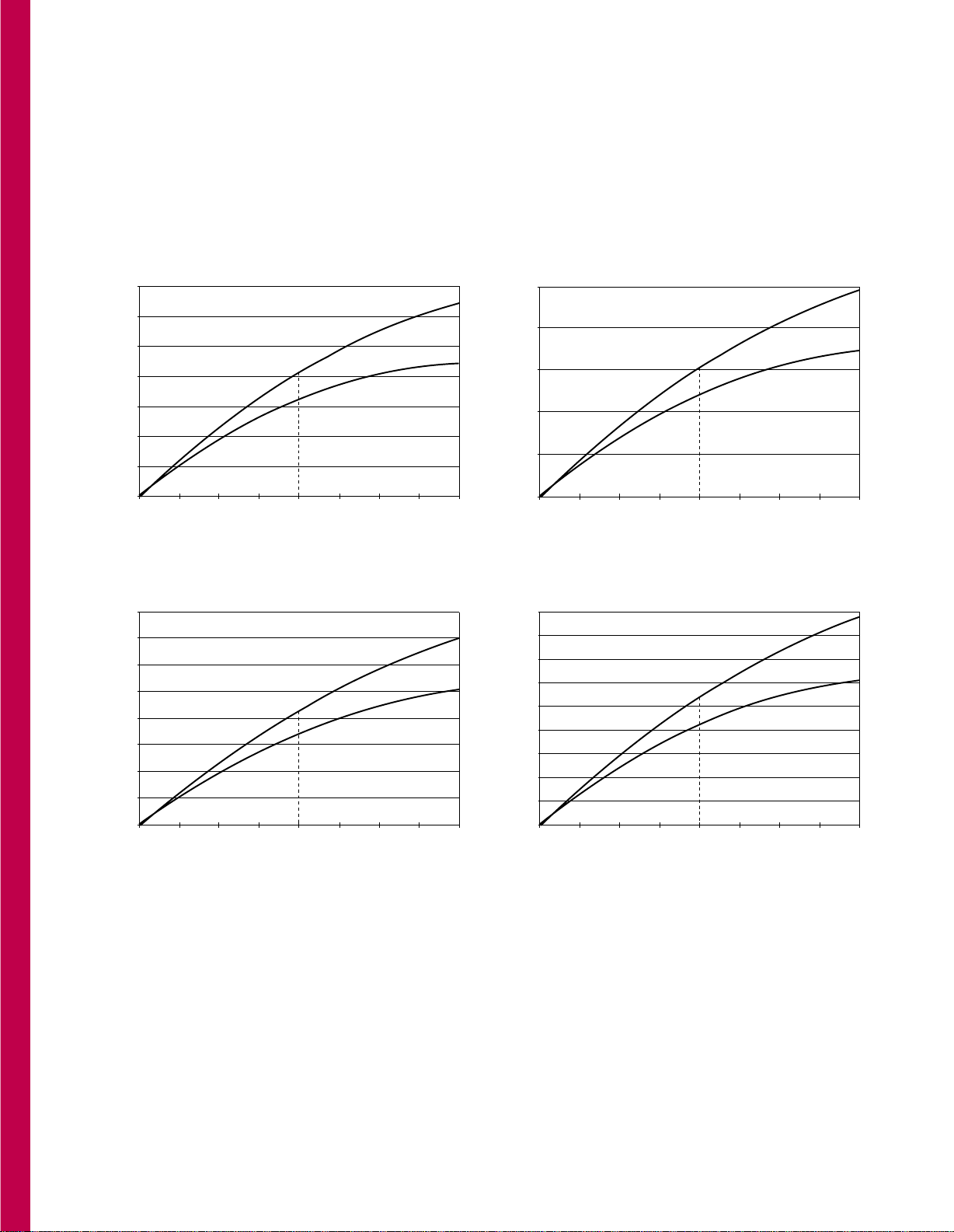
NEMA 34 FRAME (3.38" Square)—Performance
Motors will perform continuously as shown without the winding temperature exceeding 130°C when the motor is operated (without heat sink) in
an ambient temperature of up to 40°C. The curves do not reflect system resonance points, which will vary with motor coupling and system
parameters.
NEMA 34 FRAME – ONE ROTOR STACK
5A per phase; K31* and N31*
J winding, parallel connection, See Ratings and Characteristics, p. 15.
SPEED (RPM)
Model Numbers*/Voltage
5A per phase
K31HXHJ-...; 75V
N31HXHJ-...; 75V
N31HXHJ-...; 65V
N31HXHJ-...; 40V
SPEED (FULL STEP/SEC)
TORQUE (OZ-IN.)
TORQUE (Nm)
0
100
200
300
400
500
600
700
0 300 600 900 1200 1500 1800
0 1000 2000 3000 4000 5000 6000
0
0.7
1.4
2.1
2.8
3.5
4.2
4.9
NEMA 34 FRAME – TWO ROTOR STACKS
5A per phase; K32* and N32*
J winding, parallel connection, See Ratings and Characteristics, p. 16.
0 600 1200 1800 2400
0 2000 4000 6000 8000
0
200
400
600
800
1000
1200
1400
0
1.4
2.8
4.2
5.7
7.0
8.5
9.9
SPEED (RPM)
SPEED (FULL STEP/SEC)
TORQUE (OZ-IN.)
TORQUE (Nm)
K32HXHJ-...; 75V
N32HXHJ-...; 75V
N32HXHJ-...; 65V
N32HXHJ-...; 40V
Model Numbers*/Voltage
5A per phase
*See Model Number Code on page 14 for clarification.
www.pacsci.com
22
POWERPAC
HYBRIDS
NEMA 34 FRAME (3.38" Square)—Performance
Motors will perform continuously as shown without the winding temperature exceeding 130°C when the motor is operated (without heat sink) in
an ambient temperature of up to 40°C. The curves do not reflect system resonance points, which will vary with motor coupling and system
parameters.
NEMA 34 FRAME – THREE ROTOR STACKS
5A per phase; K33* and N33*
J winding, parallel connection, See Ratings and Characteristics, p. 17.
0 600 1200 1800 2400
0 2000 4000 6000 8000
0
800
1200
1600
2000
400
0
5.7
8.5
11.3
14.2
2.8
SPEED (RPM)
SPEED (FULL STEP/SEC)
TORQUE (OZ-IN.)
TORQUE (Nm)
K33HXHJ-...; 75V
N33HXHJ-...; 75V
N33HXHJ-...; 65V
N33HXHJ-...; 40V
Model Numbers*/Voltage
5A per phase
NEMA 34 FRAME – FOUR ROTOR STACKS
5A per phase; K34* and N34*
J winding, parallel connection, See Ratings and Characteristics, p. 18.
0
500
1000
1500
2000
2500
3.5
7.1
10.6
14.1
17.7
0 300 900 1500 1800
0 1000 3000
600
2000 5000
1200
4000 6000
0
SPEED (RPM)
SPEED (FULL STEP/SEC)
TORQUE (OZ-IN.)
TORQUE (Nm)
K34HXHJ-...; 75V
N34HXHJ-...; 75V
N34HXHJ-...; 65V
N34HXHJ-...; 40V
Model Numbers*/Voltage
5A per phase
*See Model Number Code on page 14 for clarification.
www.pacsci.com
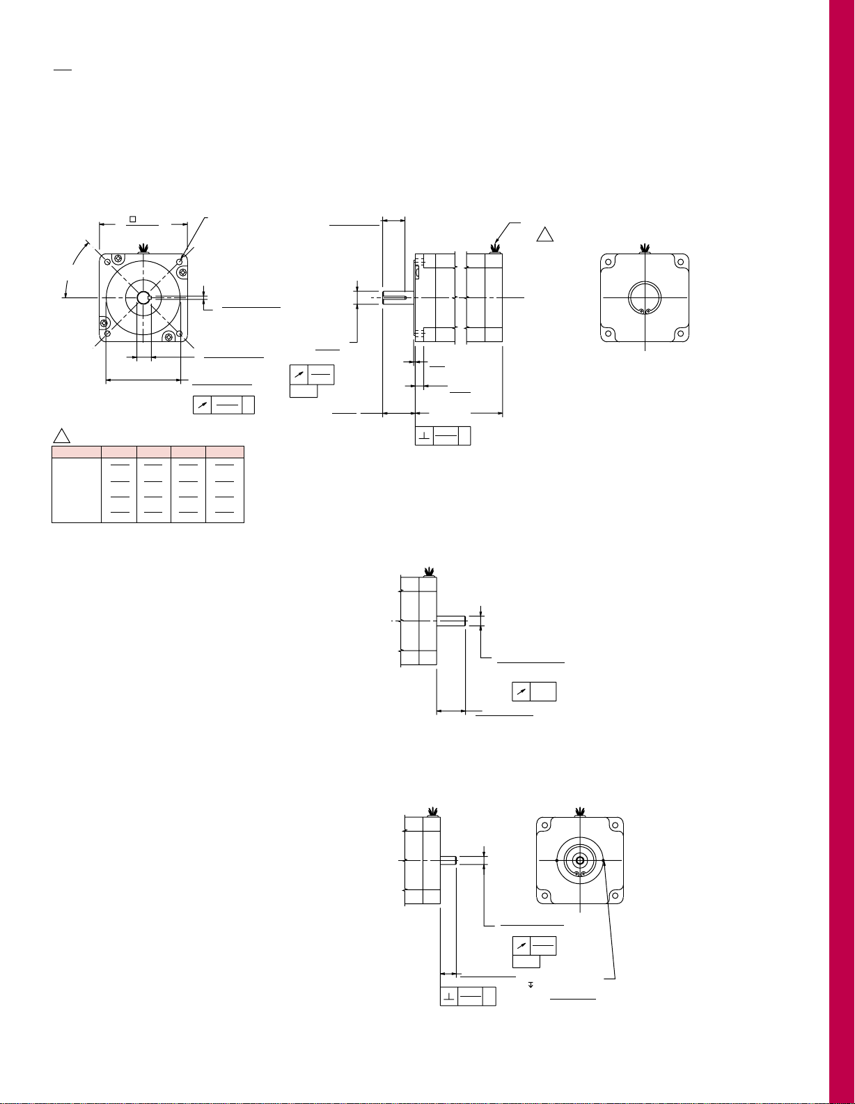
23
DIMENSIONS . . .
POWERPAC
HYBRIDS
in.
(metric dimensions for ref. only)
mm
NEMA 34 FRAME: All motors have a heavy duty NEMA front end bell and large diameter shaft to
support the higher output torques
LEADWIRE HOOKUP - ENCODER OPTIONS
Model Number Code designation R (Construction/Hookup), p. 14.
4X Ø .218 (5,537) THRU
EQUALLY SPACED ON
A Ø 3.875 (98,425) B.C.
.003
-A-
.003
0,051
0,077
0,077
Ø D
+.0000
(0,013)
-.0005
1
+.000
–.017 (-0,432)
K
+.0000
–.0020 (-0,051)
.002
( 3.38)
(85,852)
.06
1,52
L MAX.
Ø 2.875 ± .002
73,025 ± 0,051
(2X 45°)
1.25
31,750
MOTOR LEADS
.875 ± .010
22,23 ± 0,254
(.33)
(8,38)
T
NOTES:
1 MOTOR LEADS 12.0 MIN.
A
A
LEADWIRE HOOKUP
DOUBLE SHAFT CONFIGURATION
Model Number Code designation D (Shaft Configuration), p. 14.
LEADWIRE HOOKUP
ENCODER MOUNTING PROVISION
Model Number Code designation M2
(Encoder Mounting Options), p. 14.
Ø .3148
8,000
+.0000
–.0005
-B-
.002
0,051
.003
0,077
ON A Ø 1.812 B.C.
46,025
.625 ± .040
15,875 ± 1,016
2X 2-56 UNC-2B
.20 MIN.
-0,013
B
MOTOR D K T L MAX
.5000 .1250 .555 3.13
31 HR
12,700 3,175 14,097 79,502
.5000 .1250 .555 4.65
32 HR
12,700 3,175 14,097 118,11
.6250 .1875 .705 6.13
33 HR
15,875 4,763 17,907 155,70
.6250 .1875 .705 7.68
34 HR
15,875 4,763 17,907 195,07
Ø .3750
9,525
+.0000
–.0005
.002
0,051
1.12 ± .06
28,448 ± .1,520
-0,013
www.pacsci.com
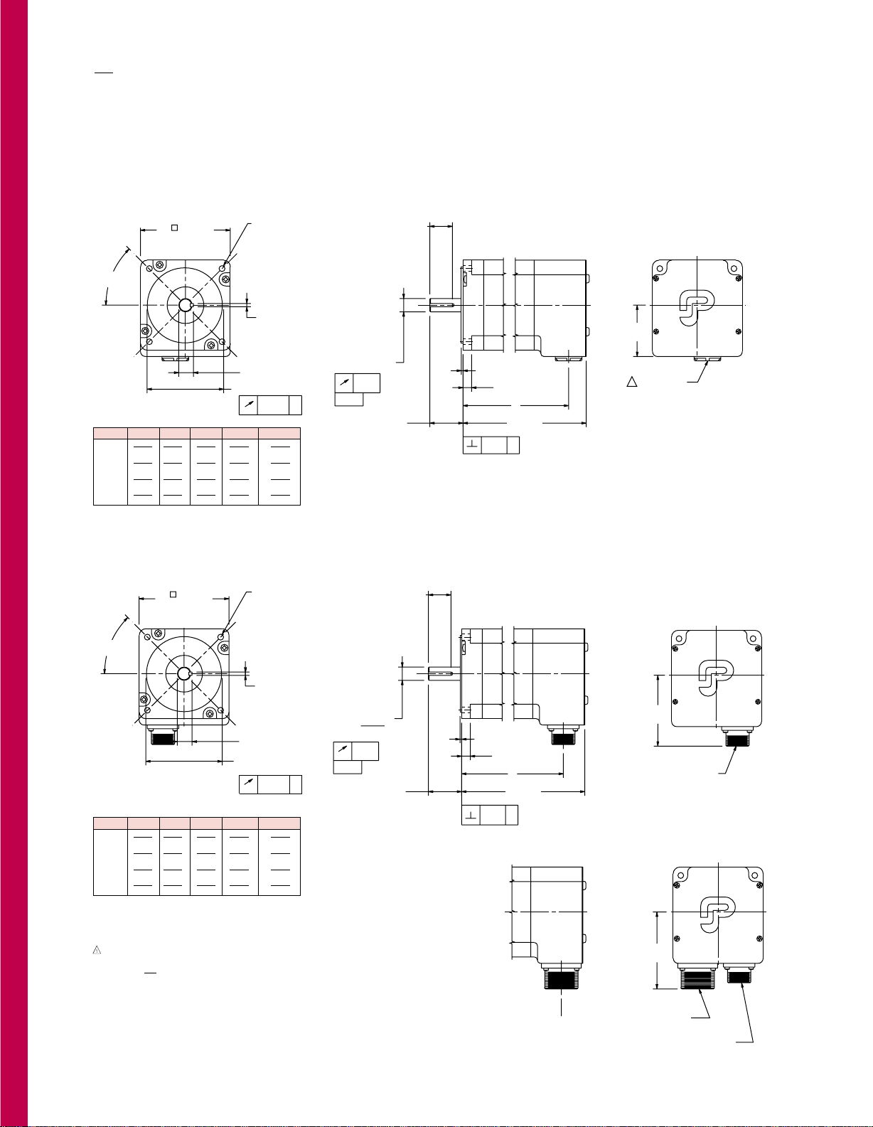
24
ENCODER
MOUNTING OPTION
DIMENSIONS . . .
POWERPAC
HYBRIDS
in.
(metric dimensions for ref. only)
mm
NEMA 34 FRAME: All motors have a heavy duty NEMA front end bell and large diameter shaft to
support the higher output torques
SPLASHPROOF CONSTRUCTION/TERMINAL BOARD CONNECTIONS
(via English or Metric thread for conduit) Model Number Code designation L or M (Construction/Hookup), p 14.
SPLASHPROOF CONSTRUCTION/MS CONNECTOR(S)— ENCODER OPTION
Model Number Code designation C/System (Construction/Hookup) and Encoder Mounting Option, p 14.
4X Ø .218 (5,537) THRU
EQUALLY SPACED ON
A Ø 3.875 (98,425) B.C.
.003 A
0,077
-A-
.003 A
Ø D
+.0000
–.0005 (-0,013)
+.000
–.017 (0,432)
K
+.0000
–.0020 (-0,508)
.002
0,077
0,051
Removable
Insulating Bushing
( 3.38)
85,852
.06
Ø 2.875 ± .002
(2X 45°)
1.25
31,750
.875 ± .010
22,23 ± 0,254
(.33)
1,52
(8,38)
T
L MAX.
X
1.95 (49,53)
MAX.
1
Construction = Conduit
connection (1/2 NPSC TAP)
with
.56
I.D. removable
insulating bushing
Construction = Conduit
connection (PG 11 TAP).
(No insulating bushing
supplied)
L
M
14,2
.003 A
0,077
4X Ø .218 (5,537) THRU
EQUALLY SPACED ON
A Ø 3.875 (98,425) B.C.
.003 A
-A-
Ø D
+.0000
–.0005
-0,013
+.000
–.017 (-0,432)
K
+.0000
–.0020 (-0,508)
.002
0,077
0,051
.06
(.33)
1,52
8,38
L MAX.
( 3.38)
85,852
Ø 2.875 ± .002
73,025 ± 0,051
(2X 45°)
2.69 (68,33)
MAX.
X
MOTOR CONNECTOR
1.25
31,75
.875 ± .010
22,23 ± .0,254
T
ENCODER
CONNECTOR
MOTOR CONNECTOR
2.92 (74,17)
MAX.
X dimension same
as above
MOTOR D K T X L MAX
.5000 .1250 .555 3.70 4.44
31 HL
12,700 3,175 14,097 93,98 112,78
.5000 .1250 .555 5.22 5.96
32 HL
12,700 3,175 14,097 132,59 151,38
.6250 .1875 .705 6.74 7.48
33 HL
15,875 4,763 17,907 171,20 189,99
.6250 .1875 .705 8.25 8.99
34 HL
15,875 4,763 17,907 209,55 228,35
* See Model Number Code, p 14.
MOTOR D K T X L MAX
.5000 .1250 .555 3.56 4.44
31 HC
12,700 3,175 14,097 90,42 112,78
.5000 .1250 .555 5.07 5.96
32 HC
12,700 3,175 14,097 128,78 151,38
.6250 .1875 .705 6.59 7.48
33 HC
15,875 4,763 17,907 165,10 189,99
.6250 .1875 .705 8.11 8.99
34 HC
15,875 4,763 17,907 205,99 228,35
* See Model Number Code, p 14.
NOTES:
www.pacsci.com
25
POWERPAC™HYBRIDS
NEMA 42 Frame
(4.325" Square)
Basic Series
K=Sigmax
®
N=Standard
K4 3 HCHJ-LEK-M2 -01
Number of
Rotor Stacks
1=1 Stacks
2=2 Stacks
3=3 Stacks
Winding Type
J-(only on 1 stack),
K-(n/a on 1 stack),
L,
N-(n/a on 1 stack),
M=Standards
S=Special, call
factory
Winding/Leads
L=4 Lead series
H=4 Lead parallel
E=6 Lead (N/A
C construction)
F=8 Lead (N/A
C construction)
Special Sequence
00=Standard motor–
no shaft seal
01=Standard motor
with shaft seal.
Other #’s will be
assigned for special
motors
Construction/Hookup
R=Regular/leadwire
C=System
MS connector
L=Splashproof/to
terminal board via
conduit connector: 1/2"
NPSC pipe thread
M=Splashproof/to
terminal board via
conduit connector:
metric PG13,5 pipe
thread
S=Special, call factory
Size
4=NEMA 42 frame size;
4.325" width/height,
square frame
Encoder Option
NS=No feedback
All of the configurations listed below
must use construction C or R and
shaft configuration E:
M2=Encoder mounting provisions
SS=Special, call factory
Shaft Modifications
K=Straight key
S=Special, call factory
Shaft Configuration
(Diameter & Length)
N=Single
D=Double (R or C
construction only)
E=Double ended for
encoder (R or C
construction only)
S=Special, call factory
Rotor Type
L=Laminated
Mounting
Configuration
H=Heavy duty
NEMA
S=Special, call
factory
MODEL NUMBER CODE
HOW TO ORDER
Review the Motor Model Number Code to assure that all options are designated. Call your nearest Pacific
Scientific Motor Products Distributor to place orders and for application assistance. If you need to identify
your Distributor, call the Motor Products Division at (815) 226-3100.
The example model number above indicates a K series (Sigmax
®
) NEMA 42 frame motor with a three stack
rotor. This motor is equipped with a heavy duty front end bell and shaft, and a sealed system rear end bell
with MS connectors. It also has a bipolar parallel connection, a J winding, a straight keyway, a shaft seal
and encoder mounting provisions.
www.pacsci.com
26
POWERPAC
HYBRIDS
Also see:
• Torque and Acceleration Comparisons, p. 19, 29
• Torque Linearity, p. 29
• Performance Curves, p. 30-31
NEMA 42 FRAME (4.325" Square)—Ratings and Characteristics
Review the Model Number Code, page 25, to assure that all options are designated. Connections, encoders and
phasing diagrams start on page 34. Motor dimensions start on page 32. In addition to those below, motors with
characteristics for specific performance requirements are offered. Contact factory for more details.
Connection Holding
Torque Phase
Rated Inductance
Current/ Phase Thermal Rotor
Motor (2 phases on) Phase Resistance Detent Resistance Inertia
Model Number oz-in (Nm) (ohms) (mH) Torque oz-in-S
2
Weight
±10% (amps DC) ±10% Typical oz-in (Nm) (oC/watt) (kgm2x 10-3) lbs (kg)
K41HXHM-LXK-XX-XX • 2135(15.07) 10.7 0.16 2.2
K41HXLM-LXK-XX-XX • 2135(15.07) 5.3 0.63 8.7
K41HXEM-LXK-XX-XX • 1510(10.66) 7.5 0.31 2.2
K41HXHL-LXK-XX-XX • 2090(14.75) 8.7 0.23 3.1
K41HXLL-LXK-XX-XX • 2090(14.75) 4.4 0.93 12.3
K41HXEL-LXK-XX-XX • 1480(10.45) 6.2 0.47 3.1
K41HXHJ-LXK-XX-XX • 2095(14.79) 5.5 0.58 7.8
K41HXLJ-LXK-XX-XX • 2095(14.79) 2.7 2.33 31.4
K41HXEJ-LXK-XX-XX • 1480(10.45) 3.9 1.16 7.8
N41HXHM-LXK-XX-XX • 1655(11.68) 10.7 0.16 2.8
N41HXLM-LXK-XX-XX • 1655(11.68) 5.3 0.63 11.1
N41HXEM-LXK-XX-XX • 1170(8.26) 7.5 0.31 2.8
N41HXHL-LXK-XX-XX • 1625(11.47) 8.7 0.23 3.9
N41HXLL-LXK-XX-XX • 1625(11.47) 4.4 0.93 15.8
N41HXEL-LXK-XX-XX • 1150(8.12) 6.2 0.47 3.9
N41HXHJ-LXK-XX-XX • 1630(11.50) 5.5 0.58 10.1
N41HXLJ-LXK-XX-XX • 1630(11.50) 2.7 2.33 40.4
N41HXEJ-LXK-XX-XX • 1150(8.12) 3.9 1.16 10.1
Parallel
Series
Unipolar
Rated currents are in
descending order
Torque range:
1480-2135 oz-in.
92.5-133.4 lb-in.
10.45-15.07 Nm
K Series SIGMAX
®
1 rotor stack
65 1.9 0.0783 11
(0.46) (0.55) (4.98)
Torque range:
1150-1655 oz-in.
78.1-103.4 lb-in.
8.12-11.68 Nm
N Series Standard
1 rotor stack
42 1.9 0.0783 11
(0.30) (0.55) (4.98)
All ratings typical and at 25°C unless otherwise noted.
An ”X” in the Model Number Code indicates an undefined
option. Colored letter indicates winding. See Model Number
Code on page 25.
Motor connections are determined by the Windings/Leads
designation in the Model Number Code on page 25. Note that
the F designation, although not shown in the above tables, is
an 8-lead option...see Terminations, page 34. In addition to the
lead wire termination, terminal board and MS connector hookup
for parallel, series or unipolar operation is also available.
With rated current applied. Windings at 130°C and motor
unmounted and in still air at 40°C.
Windings at 130°C and motor in still air at 40°C (without heat sink).
Motors may be operated up to 2 times rated current to provide
high peak torque with good torque linearity - duty cycle
dependant, contact factory.
Small signal inductance as measured with impedance bridge at
1kHz, 1 amp.
Thermal resistance measured with motor hanging in still air
(unmounted).
www.pacsci.com
27
Connection Holding
Torque Phase
Rated Inductance
Current/ Phase Thermal Rotor
Motor (2 phases on) Phase Resistance Detent Resistance Inertia
Model Number oz-in (Nm) (ohms) (mH) Torque oz-in-S
2
Weight
±10% (amps DC) ±10% Typical oz-in (Nm) (oC/watt) (kgm2x 10-3) lbs (kg)
K42HXHN-LXK-XX-XX • 4000(28.23) 15.8 0.1 1.6
K42HXLN-LXK-XX-XX • 4000(28.23) 7.9 0.41 6.5
K42HXEN-LXK-XX-XX • 2830(19.97) 11.2 0.21 1.6
K42HXHM-LXK-XX-XX • 4025(28.41) 9.9 0.25 4.2
K42HXLM-LXK-XX-XX • 4025(28.41) 4.9 1.02 16.9
K42HXEM-LXK-XX-XX • 2845(20.08) 7 0.51 4.2
K42HXHL-LXK-XX-XX • 3935(27.77) 8.1 0.38 6
K42HXLL-LXK-XX-XX • 3935(27.77) 4 1.51 23.9
K42HXEL-LXK-XX-XX • 2785(19.66) 5.7 0.75 6
K42HXHK-LXK-XX-XX • 3965(27.99) 6.4 0.6 9.8
K42HXLK-LXK-XX-XX • 3965(27.99) 3.2 2.41 39.2
K42HXEK-LXK-XX-XX • 2805(19.80) 4.5 1.2 9.8
N42HXHN-LXK-XX-XX • 3130(22.09) 15.8 0.1 2.1
N42HXLN-LXK-XX-XX • 3130(22.09) 7.9 0.41 8.4
N42HXEN-LXK-XX-XX • 2215(15.63) 11.2 0.21 2.1
N42HXHM-LXK-XX-XX • 3145(22.20) 9.9 0.25 5.5
N42HXLM-LXK-XX-XX • 3145(22.20) 4.9 1.02 22
N42HXEM-LXK-XX-XX • 2225(15.70) 7 0.51 5.5
N42HXHL-LXK-XX-XX • 3085(21.77) 8.1 0.38 7.8
N42HXLL-LXK-XX-XX • 3085(21.77) 4 1.51 31.2
N42HXEL-LXK-XX-XX • 2185(15.42) 5.7 0.75 7.8
N42HXHK-LXK-XX-XX • 3105(21.92) 6.4 0.6 12.8
N42HXLK-LXK-XX-XX • 3105(21.92) 3.2 2.41 51.1
N42HXEK-LXK-XX-XX • 2200(15.53) 4.5 1.2 12.8
Parallel
Series
Unipolar
Rated currents are in
descending order
Torque range:
2785-4025 oz-in.
174.0-251.5 lb-in.
19.66-28.41 Nm
K Series SIGMAX
®
2 rotor stacks
126 1.3 0.1546 18.4
(0.89) (1.09) (8.34)
Torque range:
2185-3145 oz-in.
136.5-196.5 lb-in.
15.42-22.2 Nm
N Series Standard
2 rotor stacks
84 1.3 0.1546 18.4
(0.59) (1.09) (8.34)
All ratings typical and at 25°C unless otherwise noted.
An ”X” in the Model Number Code indicates an undefined
option. Colored letter indicates winding. See Model Number
Code on page 25.
Motor connections are determined by the Windings/Leads
designation in the Model Number Code on page 25. Note that
the F designation, although not shown in the above tables, is
an 8-lead option...see Terminations, page 34. In addition to the
lead wire termination, terminal board and MS connector hookup
for parallel, series or unipolar operation is also available.
With rated current applied. Windings at 130°C and motor
unmounted and in still air at 40°C.
Windings at 130°C and motor in still air at 40°C (without heat sink).
Motors may be operated up to 2 times rated current to provide
high peak torque with good torque linearity - duty cycle
dependant, contact factory.
Small signal inductance as measured with impedance bridge at
1kHz, 1 amp.
Thermal resistance measured with motor hanging in still air
(unmounted).
POWERPAC
HYBRIDS
Also see:
• Torque and Acceleration Comparisons, p. 19, 29
• Torque Linearity, p. 29
• Performance Curves, p. 30-31
NEMA 42 FRAME (4.325" Square)—Ratings and Characteristics (Con’t)
Review the Model Number Code, page 25, to assure that all options are designated. Connections, encoders and
phasing diagrams start on page 34. Motor dimensions start on page 32. In addition to those below, motors with
characteristics for specific performance requirements are offered. Contact factory for more details.
www.pacsci.com
28
Connection Holding
Torque Phase
Rated Inductance
Current/ Phase Thermal Rotor
Motor (2 phases on) Phase Resistance Detent Resistance Inertia
Model Number oz-in (Nm) (ohms) (mH) Torque oz-in-S
2
Weight
±10% (amps DC) ±10% Typical oz-in (Nm) (oC/watt) (kgm2x 10-3) lbs (kg)
K43HXHN-LXK-XX-XX • 5700(40.23) 15.4 0.14 2.5
K43HXLN-LXK-XX-XX • 5700(40.23) 7.7 0.55 10
K43HXEN-LXK-XX-XX • 4030(28.44) 10.9 0.28 2.5
K43HXHM-LXK-XX-XX • 5630(39.74) 9.9 0.33 5.9
K43HXLM-LXK-XX-XX • 5630(39.74) 4.9 1.32 23.7
K43HXEM-LXK-XX-XX • 3985(28.13) 7 0.66 5.9
K43HXHL-LXK-XX-XX • 5530(39.03) 8 0.5 8.5
K43HXLL-LXK-XX-XX • 5530(39.03) 4 1.98 34.1
K43HXEL-LXK-XX-XX • 3910(27.60) 5.7 0.99 8.5
K43HXHK-LXK-XX-XX • 5655(39.91) 6.2 0.82 15.2
K43HXLK-LXK-XX-XX • 5655(39.91) 3.1 3.29 60.7
K43HXEK-LXK-XX-XX • 4000(28.23) 4.4 1.65 15.2
N43HXHN-LXK-XX-XX • 4365(30.81) 15.4 0.14 3.2
N43HXLN-LXK-XX-XX • 4365(30.81) 7.7 0.55 13
N43HXEN-LXK-XX-XX • 3090(21.81) 10.9 0.28 3.2
N43HXHM-LXK-XX-XX • 4320(30.49) 9.9 0.33 7.7
N43HXLM-LXK-XX-XX • 4320(30.49) 4.9 1.32 30.7
N43HXEM-LXK-XX-XX • 3055(21.56) 7 0.66 7.7
N43HXHL-LXK-XX-XX • 4250(30.00) 8 0.5 11
N43HXLL-LXK-XX-XX • 4250(30.00) 4 1.98 44.2
N43HXEL-LXK-XX-XX • 3010(21.24) 5.7 0.99 11
N43HXHK-LXK-XX-XX • 4340(30.63) 6.2 0.82 19.6
N43HXLK-LXK-XX-XX • 4340(30.63) 3.1 3.29 78.5
N43HXEK-LXK-XX-XX • 3070(21.67) 4.4 1.65 19.6
Parallel
Series
Unipolar
Rated currents are in
descending order
Torque range:
3910-5700 oz-in.
244.3-356.0 lb-in.
27.60-40.23 Nm
K Series SIGMAX
®
3 rotor stacks
118 1 0.2293 25.7
(0.83) (1.62) (11.64)
Torque range:
3010-4365 oz-in.
188.1-272.8 lb-in.
21.24-30.81 Nm
N Series Standard
3 rotor stacks
106 1 0.2293 25.7
(0.75) (1.62) (11.64)
All ratings typical and at 25°C unless otherwise noted.
An ”X” in the Model Number Code indicates an undefined
option. Colored letter indicates winding. See Model Number
Code on page 25.
Motor connections are determined by the Windings/Leads
designation in the Model Number Code on page 25. Note that
the F designation, although not shown in the above tables, is
an 8-lead option...see Terminations, page 34. In addition to the
lead wire termination, terminal board and MS connector hookup
for parallel, series or unipolar operation is also available.
With rated current applied. Windings at 130°C and motor
unmounted and in still air at 40°C.
Windings at 130°C and motor in still air at 40°C (without heat sink).
Motors may be operated up to 2 times rated current to provide
high peak torque with good torque linearity - duty cycle
dependant, contact factory.
Small signal inductance as measured with impedance bridge at
1kHz, 1 amp.
Thermal resistance measured with motor hanging in still air
(unmounted).
POWERPAC
HYBRIDS
Also see:
• Torque and Acceleration Comparisons, p. 19, 29
• Torque Linearity, p. 29
• Performance Curves, p. 30-31
NEMA 42 FRAME (4.325" Square)—Ratings and Characteristics (Con’t)
Review the Model Number Code, page 25, to assure that all options are designated. Connections, encoders and
phasing diagrams start on page 34. Motor dimensions start on page 32. In addition to those below, motors with
characteristics for specific performance requirements are offered. Contact factory for more details.

www.pacsci.com
29
POWERPAC
HYBRIDS
NEMA 42 FRAME (4.325" Square)—Torque and Acceleration Comparisons
For comparison with size 34 motor, see page 19.
Holding Torque
N41
0
1000
1655
2135
3145
4025
4365
5700
2000
3000
4000
5000
6000
K41
N42
K42
N43
K43
Motor Model/Stack Length
Acceleration
rad
x 10 *
s
2
3
30.0
25.0
20.0
21.1
27.3
20.3
K41N41 K42N42
K43N43
26.0
19.0
24.9
15.0
10.0
5.0
0
* Holding Torque
...a figure of merit for acceleration capability
Rotor Inertia
NEMA 42 FRAME (4.325" Square)—Torque Linearity
A significant POWERPAC performance attribute is that when a current higher than rated current is applied, the increase in torque will be more
linear than other hybrids. Furthermore, current levels increasingly higher than rated current are less likely to cause demagnetization. Capitalize
on this performance characteristic which will provide an acceleration boost to move loads even faster. This technique is applicable to
intermittent duty applications in that the thermal limit of the motor cannot be exceeded. Driving the motor at higher than rated current is duty
cycle dependent. Contact the factory for application assistance.
These curves show the torque at rated current and the torque linearity up to two times rated current.
Current
[Amps]
K43
N43
Rated Current
Current
[Amps]
K42
N42
Rated Current
0 3.8
9000
7.7 11.5 15.4 19.2 23.1 26.9 30.8
8000
7000
4000
3000
6000
5000
2000
1000
63.5
56.5
49.4
28.2
21.1
42.3
35.3
14.1
7.0
0
0 3.9
7000
7.9 11.8 15.8 19.7 23.7 27.6 31.6
6000
5000
3000
2000
4000
1000
49.4
42.3
35.3
21.1
14.1
28.2
7.0
0
0 2.6
3500
5.3 8.0 10.7 13.3 16.0 18.7 21.4
3000
2500
1500
1000
2000
500
24.7
21.1
17.6
10.6
7.0
14.1
3.5
0
Current
[Amps]
K41
N41
Rated Current
TORQUE LINEARITY
N & K 41 M-Winding
(bipolar parallel connection)
TORQUE LINEARITY
N & K 43 N-Winding
(bipolar parallel connection)
TORQUE LINEARITY
N & K 42 N-Winding
(bipolar parallel connection)
Holding Torque [Oz-in]
Holding Torque [Oz-in]
Holding Torque [Nm]
Holding Torque [Oz-in]
Holding Torque [Nm]
Holding Torque [Nm]

www.pacsci.com
30
POWERPAC
HYBRIDS
NEMA 42 FRAME (4.325" Square)—Performance
Motors will perform continuously as shown without the winding temperature exceeding 130°C when the motor is operated (without heat sink) in
an ambient temperature of up to 40°C. The curves do not reflect system resonance points, which will vary with motor coupling and system
parameters.
NEMA 42 FRAME – ONE ROTOR STACK
5A per phase; K41* and N41*
J winding, parallel connection, See Ratings and Characteristics, p. 26.
0 600 1200 1800 2400
0 2000 4000 6000 8000
0
300
600
900
1200
1500
1800
0
2.1
4.2
6.4
8.5
10.6
12.7
SPEED (RPM)
SPEED (FULL STEP/SEC)
TORQUE (OZ-IN.)
TORQUE (Nm)
K41HXHJ-...; 100V
N41HXHJ-...; 100V
N41HXHJ-...; 75V
N41HXHJ-...; 40V
Model Numbers*/Voltage
5A per phase
NEMA 42 FRAME – TWO ROTOR STACKS
8A per phase; K42* and N42*
L winding, parallel connection, See Ratings and Characteristics, p. 27.
0 300 600 900 1200 1500 1800
0 1000 2000 3000 4000 5000 6000
0
500
1000
1500
2000
2500
3000
3500
0
3.5
7.1
10.6
14.1
17.7
21.2
24.7
SPEED (RPM)
SPEED (FULL STEP/SEC)
TORQUE (OZ-IN.)
TORQUE (Nm)
K42HXHL-...; 115V
N42HXHL-...; 115V
N42HXHL-...; 100V
N42HXHL-...; 75V
Model Numbers*/Voltage
8A per phase
*See Model Number Code on page 25 for clarification.

www.pacsci.com
31
POWERPAC
HYBRIDS
NEMA 42 FRAME (4.325" Square)—Performance
Motors will perform continuously as shown without the winding temperature exceeding 130°C when the motor is operated (without heat sink) in
an ambient temperature of up to 40°C. The curves do not reflect system resonance points, which will vary with motor coupling and system
parameters.
NEMA 42 FRAME – THREE ROTOR STACKS
8A per phase; K43* and N43*
L winding, parallel connection, See Ratings and Characteristics, p. 28.
0 300 600 900 1200 1500
0 1000 2000 3000 4000 5000
0
1000
2000
3000
4000
5000
0
7.1
14.1
21.2
28.2
35.3
SPEED (RPM)
SPEED (FULL STEP/SEC)
TORQUE (OZ-IN.)
TORQUE (Nm)
K43HXHL-...; 160V
N43HXHL-...; 160V
N43HXHL-...; 100V
N43HXHL-...; 75V
Model Numbers*/Voltage
8A per phase
*See Model Number Code on page 25 for clarification.

www.pacsci.com
32
DIMENSIONS . . .
POWERPAC
HYBRIDS
in.
(metric dimensions for ref. only)
mm
NEMA 42 FRAME: All motors have a heavy duty NEMA front end bell and large diameter shaft to
support the higher output torques
LEADWIRE HOOKUP
Model Number Code designation R (Construction/Hookup), p. 25.
+.000
–.017
(0,432)
Ø .7500
+.0000
–.0005
–0,013
.1875
4,750
+.0000
–.0020
-0,051
.003 A
.002
-A-
.003 A
0,077
0,051
0,077
1
NOTES:
1 MOTOR LEADS 12.0 MIN.
.06
(2X 45°)
Ø 2.186. ± 002
Ø 55,524 ± 0,051
4X Ø .328 (8,331) THRU
EQUALLY SPACED ON A
Ø 4.950 (125,73) B.C.
2.19
55,63
1.375 ± .010
34,93 ± 0,254
.830
( 4.325)
(109,85)
L MAX.
MOTOR LEADS
(.48)
1,52
(12,19)
LEADWIRE HOOKUP
DOUBLE SHAFT CONFIGURATION
Model Number Code designation D (Shaft Configuration), p. 25.
Available on R construction only.
LEADWIRE HOOKUP
ENCODER MOUNTING PROVISION
Model Number Code designation M2
(Encoder Mounting Option), p. 25.
.003 B
Ø .3148
8,00
+.0000
–.0005
.002
0,077
0,051
-B-
ON A Ø 1.812 (46,025) B.C.
.625 ± .040
15,875 ± 10,16
2X 2-56 UNC-2B
.20 MIN. (5,08)
-0,013
MOTOR L MAX
3.89
41 HR
98,81
5.91
42 HR
150,11
7.92
43 HR
201,17
* See Model Number Code, p 25.
Ø .5000
12,700
+.0000
–.0005
.002
0,051
1.25 ± .06
31,75 ± 1,52
-0,013

www.pacsci.com
33
ENCODER
MOUNTING OPTION
DIMENSIONS . . .
POWERPAC
HYBRIDS
in.
(metric dimensions for ref. only)
mm
NEMA 42 FRAME: All motors have a heavy duty NEMA front end bell and large diameter shaft to
support the higher output torques
SPLASHPROOF CONSTRUCTION/TERMINAL BOARD CONNECTIONS
(via English or Metric thread for conduit) Model Number Code designation L or M (Construction/Hookup), p. 25
SPLASHPROOF CONSTRUCTION/MS CONNECTOR(S)— ENCODER OPTION
Model Number Code designation C/System (Construction/Hookup) and Encoder Mounting Option, p. 25.
+.000
–.017
Ø .7500
19,050
+.0000
–.0005
.1875
4,750 -0.051
+.0000
–.0020
.003 A
.002
0,051
-A-
.003 A
0,077
.06
(2X 45°)
Ø 2.186 ± .002
55,524 ± 0,051
4X Ø .328 (8,331) THRU
EQUALLY SPACED
ON A Ø 4.950 (125,73) B.C.
2.19
1.375 ± .010
34,93 ± 0,254
.830
21,082 0,432
( 4.325)
(109,85)
(.48)
X
L MAX.
2.23 (56,64)
MAX.
Removable
Insulating Bushing
1
-0,013
Construction = Conduit connection
(1/2 NPSC TAP) with
.56
I.D. removable
insulating bushing
Construction = Conduit connection (PG
13, 5 TAP). (No insulating bushing
supplied)
L
M
+.000
–.017
Ø .7500
19,050
+.0000
–.0005
.1875
4,750
+.0000
–.0020
.003 A
0,077
.002
-A-
.003 A
0,051
0,077
.06
(2X 45°)
Ø 2.186 ± .002
55,524 ± 0,051
4X Ø .328 (8,331) THRU
EQUALLY SPACED
ON A Ø 4.950 (125,73) B.C.
2.19
55,63
1.375 ± .010
34,93 ± .0,254
.830
21,082
( 4.325)
(109,85)
(.48)
1,52
(12,19)
L MAX.
MOTOR CONNECTOR
X
2.97
MAX.
-0,013
-0,051
0,432
MOTOR CONNECTOR
ENCODER
CONNECTOR
3.20
MAX.
X dimension same
as above
14,2
MOTOR* X L MAX
4.46 5.20
41 HL
113,28 132,08
6.48 7.22
42 HL
164,59 183,39
8.49 9.23
43 HL
215,65 234,44
* See Model Number Code, p 25.
MOTOR* X L MAX
4.32 5.20
41 HC
109,73 132,08
6.33 7.22
42 HC
160,78 183,39
8.35 9.23
43 HC
212,09 234,44
* See Model Number Code, p 25.
NOTES:

www.pacsci.com
34
POWERPAC™HYBRID
TECHNICAL DATA
• Hybrid motor power connections
• Phase sequencing tables
• Encoder options
HYBRID MOTOR POWER CONNECTIONS
FLYING LEADS, TERMINAL BOARD OR MS CONNECTOR
Four winding designations; F, E, L or H may be
specified in the Model Number Code. For all motor
terminations, refer to the step motor controller
connection diagram to assure that proper
connections are made. Consult our application
engineers for assistance if necessary.
DESIGNATION F . . . 8 flying leads or 8 terminals (not available in
systems construction - MS connector)
The 8 lead motor is the most versatile configuration. It may be connected by the
user in choice of 8 lead, 4 lead (series or parallel) or 6 lead configuration.
NOTE:
1. See phase sequencing tables, page 36.
CONNECTION DRIVER LEAD COLOR TERMINAL #
CONNECTION
4-LEAD BIPOLAR A BLACK (BLK) 1
SERIES
A
ORANGE (ORG) 3
B RED 2
B
YELLOW (YEL) 4
NONE WHT/BLK & WHT/ORG 6 & 5
NONE WHT/RED & WHT/YEL 8 & 7
4-LEAD BIPOLAR A BLK & WHT/ORG 1 & 5
PARALLEL
A
ORG & WHT/BLK 3 & 6
B RED & WHT/YEL 2 & 7
B
YEL & WHT/RED 4 & 8
6-LEAD UNIPOLAR A BLACK (BLK) 1
B ORANGE (ORG) 3
C RED 2
D YELLOW (YEL) 4
+V WHT/BLK & WHT/ORG 6 & 5
+V WHT/RED & WHT/YEL 8 & 7
GND GREEN/YELLOW
8-Lead Configuration
Terminal Board
NEMA 34 and 42
BLK
WHT/BLK
WHT/ORG
ORG
RED
YEL
WHT/YELWHT/RED
5
6
34
21
8
7

www.pacsci.com
35
DESIGNATION E . . . 6 flying leads or 6 terminals (not available in
systems construction - MS connector)
The 6 lead motor is normally used with unipolar drives. In some cases, the 6 lead
motor can be used in a 4 lead series configuration for use with bipolar drives.
6-Lead Configuration
Terminal Board
NEMA 34 and 42
CONNECTION DRIVER LEAD COLOR TERMINAL #
CONNECTION
6-LEAD UNIPOLAR A BLACK (BLK) 1
B ORANGE (ORG) 3
C RED 2
D YELLOW (YEL) 4
+V WHT/BLK/ORG 5
+V WHT/RED/YEL 6
4-LEAD BIPOLAR A BLACK (BLK) 1
SERIES
A
ORANGE (ORG) 3
B RED 2
B
YELLOW (YEL) 4
NONE WHT/BLK/ORG 5
NONE WHT/RED/YEL 6
GND GREEN/YELLOW
NOTE:
1. Terminals 7 and 8 are not used.
2. See phase sequencing tables, page 36.
DESIGNATION L or H. . . 4 flying leads, 4 terminals or MS connector
The 4 lead motor is for use with bipolar drives.
4-Lead Configuration
Terminal Board
MS Connector
NEMA 34 and 42
MOTOR POWER CONNECTOR
NEMA 34 & 42
MS3102R14S-5P
CONNECTION DRIVER LEAD COLOR TERMINAL # MS PIN OUT
CONNECTION
4-LEAD BIPOLAR A BLACK 1 A
A ORANGE 3 B
B RED 2 C
B YELLOW 4 D
GND GREEN/YELLOW E
NOTE:
1. Terminals 5, 6, 7 and 8 are not used.
2. See phase sequencing tables, page 36.
6
34
8
7
21
5
YELRED
ORG
BLK
SUGGESTED MATING CONNECTOR
NEMA 34 & 42 PAC SCI P.N.
MS3106F14S-5S SZ00019
E
A
B
CD
BLK
WHT/BLK/ORG
ORG
RED
WHT/RED/YEL
YEL
34
6
5
21

www.pacsci.com
36
PHASE SEQUENCING TABLES
NOTE: Direction of rotation as viewed from mounting end of motor.
ABCD
STEP
1
2
3
4
1
6
7
8
GND
GND
GND
–
0
+
GND
GND
+
0
–
GND
GND
GND
–
–
–
GND
GND
+
+
+
AABB
STEP
1
2
3
4
5
+
+
0
–
–
–
–
0
+
+
0
+
+
+
0
0
–
–
–
0
BIPOLAR HALF STEP
PHASE SEQUENCING
CW
CCW CCW
UNIPOLAR FULL STEP
PHASE SEQUENCING
CW
AABB
STEP
1
2
3
4
1
+
–
–
+
+
–
+
+
–
–
–
–
+
+
–
+
+
–
–
+
CCW
BIPOLAR FULL STEP
PHASE SEQUENCING
CW
DRIVER CONNECTION
0
0
0
0
00
0
0
0
0
NOTES:
1. 0 = OFF OR OPEN.
2. + = POSITIVE CURRENT FLOW.
3. – = NEGATIVE CURRENT FLOW.
DRIVER CONNECTION
ENCODER OPTIONS
NEMA 34 AND NEMA 42 ENCODER MOUNTING OPTIONS
Encoder mounting options factory installed (inside).
See NEMA 34 drawing, p. 24 and
NEMA 42 drawing, p. 33.
PIN FUNCTION
A CHANNEL A
B CHANNEL A
C CHANNEL B
D CHANNEL B
E CHANNEL Z
F CHANNEL Z
G + 5 VDC
H 5 VDC RTN
ENCODER CONNECTOR
MOTOR
FEEDBACK CONNECTOR
CA3102E20-7P-A206-F80-FO
SUGGESTED
MATING CONNECTOR
PAC SCI P.N. CANNON P.N.
CZ00008 MS3106A20-7S-621
E
G
D
A
F
B
C
J
K

www.pacsci.com
37
SHAFT LOAD AND BEARING FATIGUE LIFE (L
10
)
The POWERPAC H-mount configuration has a heavy
duty NEMA front end bell and a large diameter shaft
to support the higher torque outputs.
Bearings are the only wearing component in a step
motor. PacSci uses heavy duty, long life bearings to
assure you the maximum useful life from every step
motor you purchase.
SHAFT LOADING
The maximum radial fatigue load ratings reflect the
following assumptions:
1. Motors are operated at 1 * K Series torque
2. Fully reversed radial load applied in the center of
the keyway extension
3. Infinite life with 99% reliability
4. Safety factory = 2
BEARING FATIGUE LIFE (L10) Applies to both K and N Series. See Model Number Codes on pages 14 and 25 for clarification.
Note: SPS = Speed, Full Steps Per Second
Motor* Max. Max.
Radial Force Axial Force
(Lb.) (Lb.)
31, 32 65 305
33, 34 110 305
41 125 404
42, 43 110 404
* Applies to both the K and N Series. See Model Number
Codes on pages 14 and 25 for clarification.
0
50
100
150
200
250
300
0
50
100
150
200
250
0
020406080100
0 20 40 60 80 100 120
0 20 40 60 80 100 120
0 20 40 60 80 100 120 140
50
100
150
200
250
1000 SPS
1000 SPS
2500 SPS
2500 SPS
5000 SPS
5000 SPS
10000 SPS
10000 SPS
1000 SPS
1000 SPS
2500 SPS
2500 SPS
5000 SPS
5000 SPS
10000 SPS
10000 SPS
10000 HOURS BEARING LIFE 10000 HOURS BEARING LIFE
10000 HOURS BEARING LIFE 10000 HOURS BEARING LIFE
300
0
50
100
150
200
250
300
350
AXIAL FORCE (LB)
RADIAL FORCE (LB)
31, 32 MOTORS 33, 34 MOTORS
41 MOTORS 42, 43 MOTORS
RADIAL FORCE (LB)
RADIAL FORCE (LB)
RADIAL FORCE (LB)
AXIAL FORCE (LB)
AXIAL FORCE (LB)AXIAL FORCE (LB)
Shaft Infinite Life Limit
Shaft Infinite Life Limit
Shaft Infinite Life Limit
Shaft Infinite Life Limit

www.pacsci.com
38
POWERMAX II
®
P
OWERMAX II® sets the world
performance standard for NEMA 23
step motors. At up to 253 oz-in.
holding torque, you won’t find a more
powerful two inch stepper.
With POWERMAX II you also gain
the cost advantages of design for
manufacturability (DFM) and North
America’s most advanced step motor
manufacturing line.
That makes POWERMAX II
economical without sacrificing
features - such as long life bearings,
high temperature insulation and
quality magnet materials.
Plus DFM means we can build
POWERMAX II to your specifications,
in the volumes you need, according
to your JIT or other delivery
schedule.
Standard
Standard POWERMAX II motors
come in half, single and two stacks
that provide holding torques from 42
to 253 oz-in.
Custom
POWERMAX II proves that an
economical step motor doesn’t have
to limit your options. It’s just the
opposite, thanks to flexible
manufacturing.
Whether you require a simple
drive shaft flat or an integral lead
screw, POWERMAX II motors are
made to order.
FEATURES
Two Year Warranty
New Polymer Encapsulated Stator
New Polymer End Bell with Threaded
Inserts
Largest Available Shaft Diameter on a
NEMA 23 Stepper
Oversized 30mm Bearings
Sigmax
®
Technology
Optional Low Inertia Rotor
Optional Solid Rotor
Precision Ground Rotor OD and Honed
Stator ID for Concentric Air Gap in an
Economical Motor Design
Exposed Laminations Aids Thermal
Dissipation
High Performance Gearheads
BENEFITS
High quality, dependable operation
Exceptional thermal dissipation
End bell runs cooler, provides greater
flexibility in mounting encoder and brake
options
Withstands high radial and axial loads.
Supports numerous shaft modifications.
Increases bearing fatigue life (L
10
), extends
motor life, reduces downtime
Increases available torque
Produces the highest acceleration rate
possible
High low speed torque, fast settling,
superior stiffness and damping
High quality performance in an economical
motor design.
Improved heat dissipation extends
motor life, reduces downtime.
Increases torque range in a reliable,
complete package

www.pacsci.com
39
POWERMAX II
®
HOW TO ORDER
Review the Motor Model Number Code to assure that all options are designated. Dimensions, connections and phasing diagrams start on
page 49. Encoder mounting options are on page 53.
MODEL NUMBER CODE POWERMAX II®motors
P 2 1 N R X A - L N N - N S - 0 0
Type
P=Standard
M=Enhanced
(n/a half stack)
Size
2=NEMA 23
(2.25"across flats)
Number of Stacks
H=Half stack
1=1 Stack
2=2 Stacks
Mounting
N=NEMA
S=Special
Construction
R=Regular
S=Special
Termination
X=Receptacle
F=8 Flying leads
S=Special
For X (receptacle) designation,
mating leaded connectors may
be ordered separately.
Optional GRN/YEL ground wire
available. See p. 52
Winding Type
A...per assigned letter
S=Special
Rotor Type
L=Standard
J=Low inertia
(n/a half stack)
Shaft Configuration
(Diameter & Length)
N=Single
D=Double
S=Special
Shaft Modifications
N=Smooth
F=Flat
S=Special
Sequence Number
Insert 00 if all parts
are standard. Factory
assigned if any parts
are custom.
Encoder Option
NS=No Feedback
Use encoders below.You must specify
shaft configuration D (double ended)
M1=Encoder mounting provisions
HD=Encoder 500ppr
HJ=Encoder 512ppr
SS=Special, call factory
Caution: An encoder with line
driver output may be
required for use with some
step motor controls.
Class B insulation
Exposed laminations aid
thermal dissipation
Neodymium-iron-boron
rotor magnets
All-in-one molded stator
assembly
Precision ground rotor
OD and honed stator ID for
concentric air gap
Octagonal shape simplifies
automated assembly
Integral electrical receptacle
provides high retention force of
mating connector—8 flying leads
are standard option
Optional encoders and
rear shaft extensions
Oversized 30mm bearings
increase bearing fatigue
life (L
10
) 400% over typical
22mm bearings
• Available Sigmax
®
technology
adds flux concentrating samarium
cobalt stator magnets for highest
torque and acceleration
NEMA Size 23 mounting
Many drive shaft
modifications available
Largest available shaft diameter
(0.375") on a NEMA 23 stepper
withstands high radial and axial
loads, supports numerous shaft
modifications
Rugged end bell, encapsulated
windings and electrical
connector utilize high-tech
polymer
New end bell runs cooler;
encoder life is enhanced
The example model number above indicates a standard NEMA 23 frame motor with a one stack rotor. This motor is equipped with a standard
NEMA mount, regular construction, receptacle and an A winding. It also has a standard rotor, a smooth single-ended shaft and no encoder or
encoder mounting provisions.

www.pacsci.com
40
POWERMAX II
®
INDEX
How to use this section
This section covers our
high performance NEMA
23 frame POWERMAX II
®
hybrid stepper motors.
• If you’re new to
POWERMAX IIand PacSci
we’d recommend you
review the Application
Assistance section on pages
6 - 9.
• If you’re familiar with
POWERMAX II you can use
the index at right to
quickly locate the
information you need for
your application.
Technical overview
Pages 41-44
Rating and
characteristics
Pages 45-47
Dimensions
Page 49
Connection information
Pages 49, 50
Encoder options
Page 53
•Cost/performance
•Comparison of standard and Sigmax®enhanced
hybrid technologies
•Technical specifications
•Model number code
•P Series standard hybrids: 1/2, 1 and 2 stacks
•M Series Sigmax®hybrids: 1 and 2 stacks
•Holding torque range: 42 to 253 oz-in.
•72 standard models with laminated rotors
•Low inertia rotors for highest acceleration rates:
12 standard models
•Dimensional drawings
•Shaft details and options
•See illustrated examples of additional standard
options on page 49
•Terminations
•Phase sequencing
•Bipolar and unipolar windings
•Optional leaded connectors
•Optional mating connectors
•See illustrated examples of optional connectors on
page 52
•Agilent Technologies HEDS 5600 Series
•Dimensional drawings
•Mounting provisions
•See illustrated examples of encoder options on
page 53

www.pacsci.com
41
POWERMAX II
HYBRIDS
SELECTION OVERVIEW
POWERMAX II®HYBRIDS
Page
NEMA 23
(2.3" square frame)
Holding torque range
oz-in. (Nm)
95-144
(0.67-1.02)
161-253
(1.13-1.79)
42-61
(0.29-0.43)
77-116
(0.54-0.82)
138-214
(0.97-1.51)
99-140
(0.70-0.99)
178-252
(1.26-1.78)
79-111
(0.55-0.78)
142-201
(1.00-1.42)
1 Stack
2 Stacks
1/2 Stack
1 Stack
2 Stacks
1 Stack
2 Stacks
1 Stack
2 Stacks
M Series – Sigmax®Technology
P Series – Standard Hybrid
M “J” Series - Sigmax Technology Low Inertia Rotor
P “J” Series - Sigmax Hybrid Low Inertia Rotor
46
47
45
46
47
48
48
48
48

www.pacsci.com
42
SPECIALS
POWERMAX II
®
GIVES
YOU OPTIONS
POWERMAX II®proves that an
economical step motor doesn’t have
to limit your options. It’s just the
opposite, thanks to flexible
manufacturing.
Whether you require a simple drive
shaft flat or an integral lead screw,
POWERMAX II motors are made to
your order.
To give us your specifications, just
use the guide on page 6 - 9 of this
catalog.
Standard Motor
Clockwise from right: POWERMAX II
motors come in half, single and
double rotor stacks in holding
torques from 42 to 253 oz-in.
Typical modifications
Large diameter drive shaft
POWERMAX II offers the largest diameter (0.375")
drive shaft available in a NEMA 23 step motor.
Large diameter drive shaft with flat withstands
high radial and axial loads, supports numerous
shaft modifications.
Large diameter drive shaft with special flat.
Popular flats
Extended length drive shaft with flat.
Two flats on drive shaft permit use of dual
setscrews for increased locking force.
Flat extending full length of long drive shaft for
secure engagement.

www.pacsci.com
43
SPECIALS
Drive shaft modifications Drive shaft add-ons
Acme lead screw fixed to drive shaft.
Helical gear press-fitted to drive shaft.
Encoder options
Encoder-ready rear shaft extension and
mounting provision (1.812" bolt circle) accepts
popular encoders.
Internal threaded, drive shaft. Flat. Threaded
mounting inserts in front end cap.
Cross-drilled shaft accepts hardened roll pin to
attach sleeves, pulleys and gears.
Slotted drive shaft permits screwdriver
adjustment for applications requiring manual
shaft positioning. Flat on shaft.
Extended, stepped down shaft machined as two
mating parts.
Hardened steel gear extension press-fitted to
drive shaft.
Agilent Technologies HEDS 5600 encoder
(without line driver outputs) mounted on rear
shaft extension and end cap.
Plastic gear with brass bushing attached by
hardened roll pin through cross-drilled hole
in shaft.

www.pacsci.com
44
Pacific Scientific developed POWERMAX II®to be the
best cost/performance value available in hybrid step
motors.
That’s why you’ll find so many standard
POWERMAX II models in the universal NEMA 23
frame size. With POWERMAX II, you can tailor motor
torque, acceleration and inertia to every axis of your
design. And you can do this economically too, using
a single mounting configuration and the driver of your
choice.
Does your application require that extra measure of
performance? Then consider the POWERMAX II M
Series, featuring the patented Sigmax
®
technology.*
Samarium cobalt magnets in M Series motors
concentrate magnetic flux at desired points between
the rotor and stator. Sigmax technology optimizes flux
paths to increase torque production and current
utilization over conventional hybrid designs.
M SERIES ENHANCED HYBRID
SIGMAX®TECHNOLOGY
P SERIES STANDARD HYBRID
Types
POWERMAX II M Series . . . . . . . . . . . . . . . . . . . . . . . . . . . . . . . . . . . . Hybrid step motors with rare earth magnets
in the stator teeth
POWERMAX II P Series . . . . . . . . . . . . . . . . . . . . . . . . . . . . . . . . . . . . Hybrid step motors
Rotor construction
POWERMAX II M and P Series;
with “L” rotor designates . . . . . . . . . . . . . . . . . . . . . . . . . . . . . . . . . . . . Laminated
(high speed efficiency)
POWERMAX II M and P Series;
with “J” rotor designates . . . . . . . . . . . . . . . . . . . . . . . . . . . . . . . . . . . . . Low mass/low inertia (fast start/stop,
high acceleration)
Windings
A, B, C, D, E, F, G . . . . . . . . . . . . . . . . . . . . . . . . . . . . . . . . . . . . . . . . . Standard winding to match any application
Phases . . . . . . . . . . . . . . . . . . . . . . . . . . . . . . . . . . . . . . . . . . . . . . . . . . . . . . . . 2
Full steps per revolution . . . . . . . . . . . . . . . . . . . . . . . . . . . . . . . . . . . . . . . . . . . . . 200
Full step angle . . . . . . . . . . . . . . . . . . . . . . . . . . . . . . . . . . . . . . . . . . . . . . . . . . . . . 1.8 °
Angular accuracy
POWERMAX II M and M “J” . . . . . . . . . . . . . . . . . . . . . . . . . . . . . . . . . . ±1.5% of one step, no load,
non-cumulative
POWERMAX II P and P “J” . . . . . . . . . . . . . . . . . . . . . . . . . . . . . . . . . . ±3% of one step, no load,
non-cumulative
Operating temperature . . . . . . . . . . . . . . . . . . . . . . . . . . . . . . . . . . . . . . . . . . . . . . . -20 to 40°C
Insulation . . . . . . . . . . . . . . . . . . . . . . . . . . . . . . . . . . . . . . . . . . . . . . . . . . . . . . . NEMA Class B, 130°C
Insulation resistance . . . . . . . . . . . . . . . . . . . . . . . . . . . . . . . . . . . . . . . . . . . . . . . . 100 Megohms @500V dc and 25°C
Shaft load ratings
Max. radial load (at center of std. shaft extension) . . . . . . . . . . . . . . . . . 20 lb.
Max. axial load (on front shaft extension toward motor) . . . . . . . . . . . . . 13 lb.
Bearing life . . . . . . . . . . . . . . . . . . . . . . . . . . . . . . . . . . . . . . . . . . . . . . . . . . . . . . . Since large bearings (30 mm) are used,
life is typically about 4 times that of 22 mm
or smaller bearings used on other NEMA
Size 23 motors. POWERMAX II bearing fatigue
life (L
10
) exceeds 10,000 hours at any rotational
speed up to 10,000 full steps/second if
operated within the max. radial and axial
loads specified above.
Encoder options . . . . . . . . . . . . . . . . . . . . . . . . . . . . . . . . . . . . . . . . . . . . . . . . . . . See page 53.
TECHNICAL OVERVIEW
Patented Sigmax
®
technology* redirects magnetic
flux to inhibit leakage and
optimize torque production.
* Sigmax®technology is covered by U.S. patents
4,712,028, 4,713,470, 4,763,034 and 4,827,164.
Typical paths of flux transfer
in an energized conventional
hybrid step motor.Some flux
leakage occurs in normal
operation.
S
N
S
N
S
N
S
N
Stator
Non-torque
producing flux
Torque producing
flux
Rotor
Stator
Rare earth magnet
inserts
Focusing flux
Concentrated torque
producing flux
Rotor
POWERMAX II
®
MOTOR TECHNOLOGY

www.pacsci.com
45
POWERMAX II
®
HYBRIDS
NEMA 23 FRAME (2.3")—Ratings and Characteristics
Review the Model Number Code on page 39 to assure that all options are designated. Dimensions, connections and phasing diagrams are on
page 49. In addition to those below, motors with characteristics for specific performance requirements are offered. Contact factory for more details.
Connection Holding
Torque Phase
Rated Inductance
Current/ Phase Thermal Rotor
Motor (2 phases on) Phase Resistance Detent Resistance Inertia
Model Number oz-in (Nm) (ohms) (mH) Torque oz-in-S
2
Weight
±10% (amps DC) ±10% Typical oz-in (Nm) (oC/watt) (kgm2x 10-3) lbs (kg)
P2HNXXH-LXX-XX-00 • 59 (0.42) 5.2 0.22 0.5
P2HNXXH-LXX-XX-00 • 59 (0.42) 2.6 0.90 1.9
P2HNXXH-LXX-XX-00 • 42 (0.29) 3.68 0.44 0.5
P2HNXXB-LXX-XX-00 • 59 (0.42) 2.6 0.76 1.9
P2HNXXB-LXX-XX-00 • 59 (0.42) 1.3 3.04 7.6
P2HNXXB-LXX-XX-00 • 42 (0.29) 1.84 1.52 1.9
P2HNXXC-LXX-XX-00 • 61 (0.43) 2.5 0.84 2.3
P2HNXXC-LXX-XX-00 • 61 (0.43) 1.25 3.36 9.2
P2HNXXC-LXX-XX-00 • 43 (0.30) 1.77 1.68 2.3
P2HNXXF-LXX-XX-00 • 60 (0.42) 1.61 1.92 5.1
P2HNXXF-LXX-XX-00 • 60 (0.42) 0.80 7.68 20.4
P2HNXXF-LXX-XX-00 • 42 (0.30) 1.10 3.84 5.1
Parallel
Series
Unipolar
Rated Currents are in
descending order
Torque range:
42-61 oz-in.
.29-.43 Nm
STANDARD
P2H Series
1/2 rotor stack
2.5 0.0010 1.0
(0.018)
6.6
(0.007) (0.45)
All ratings typical and at 25°C unless otherwise noted.
An “X” in the Model Number Code indicates an undefined option.
Colored letter indicates winding. See Model Number Code on page
39.
See Model Number Code on page 39, optional leaded connectors
on page 52 and connection information on page 52.
With rated current applied. Windings at 130°C and motor
unmounted and in still air at 40°C (without heat sink).
Windings at 130°C and motor in still air at 40°C (without heat sink).
Operation of these motors above rated current may cause
demagnetization. Contact factory.
Small signal inductance as measured with impedance bridge at
1kHz, 1 amp.
Thermal resistance measured with motor hanging in still air
(unmounted).

www.pacsci.com
46
POWERMAX II
®
HYBRIDS
NEMA 23 FRAME (2.3")—Ratings and Characteristics (Con’t)
Connection Holding
Torque Phase
Rated Inductance
Current/ Phase Thermal Rotor
Motor (2 phases on) Phase Resistance Detent Resistance Inertia
Model Number oz-in (Nm) (ohms) (mH) Torque oz-in-S
2
Weight
±10% (amps DC) ±10% Typical oz-in (Nm) (
o
C/watt) (kgm2x 10-3) lbs (kg)
M21NXXA-LXX-XX-00 • 142 (1.00) 5.6 0.23 0.7
M21NXXA-LXX-XX-00 • 142 (1.00) 2.8 0.92 2.8
M21NXXA-LXX-XX-00 • 100 (0.71) 4.0 0.46 0.7
M21NXXB-LXX-XX-00 • 137 (0.97) 4.6 0.32 1.0
M21NXXB-LXX-XX-00 • 137 (0.97) 2.3 1.28 4.0
M21NXXB-LXX-XX-00 • 97 (0.68) 3.3 0.64 1.0
M21NXXC-LXX-XX-00 • 144 (1.02) 3.5 0.53 2.0
M21NXXC-LXX-XX-00 • 144 (1.02) 1.75 2.12 8.0
M21NXXC-LXX-XX-00 • 102 (0.72) 2.5 1.06 2.0
M21NXXD-LXX-XX-00 • 135 (0.95) 1.51 2.61 8.7
M21NXXD-LXX-XX-00 • 135 (0.95) 0.76 10.4 34.8
M21NXXD-LXX-XX-00 • 95 (0.67) 1.07 5.22 8.7
P21NXXA-LXX-XX-00 • 114 (0.81) 5.6 0.23 0.8
P21NXXA-LXX-XX-00 • 114 (0.81) 2.8 0.92 3.2
P21NXXA-LXX-XX-00 • 81 (0.57) 4.0 0.46 0.8
P21NXXB-LXX-XX-00 • 111 (0.79) 4.6 0.32 1.1
P21NXXB-LXX-XX-00 • 111 (0.79) 2.3 1.28 4.4
P21NXXB-LXX-XX-00 • 79 (0.55) 3.3 0.64 1.1
P21NXXC-LXX-XX-00 • 116 (0.82) 3.5 0.53 2.3
P21NXXC-LXX-XX-00 • 116 (0.82) 1.75 2.12 9.2
P21NXXC-LXX-XX-00 • 82 (0.58) 2.5 1.06 2.3
P21NXXD-LXX-XX-00 • 109 (0.77) 1.51 2.61 10.3
P21NXXD-LXX-XX-00 • 109 (0.77) 0.76 10.4 41.2
P21NXXD-LXX-XX-00 • 77 (0.54) 1.07 5.22 10.3
Parallel
Series
Unipolar
Rated Currents are in
descending order
Torque range:
95-144 oz-in.
.67-1.02 Nm
SIGMAX
®
M21 Series
1 rotor stack
9.4 0.0017 1.5
(0.066)
5.5
(0.012) (0.68)
All ratings typical and at 25°C unless otherwise noted.
An “X” in the Model Number Code indicates an undefined
option. Colored letter indicates winding. See Model Number
Code on page 39.
See Model Number Code on page 39, optional leaded
connectors on page 52 and connection information on
page 52.
With rated current applied. Windings at 130°C and motor
unmounted and in still air at 40°C (without heat sink).
Windings at 130°C and motor in still air at 40°C (without heat sink).
Operation of these motors above rated current may cause
demagnetization. Contact factory.
Small signal inductance as measured with impedance bridge at
1kHz, 1 amp.
Thermal resistance measured with motor hanging in still air
(unmounted).
4 0.0017 1.5
(0.028)
5.5
(0.012) (0.68)
Torque range:
77-116 oz-in.
.54-.82 Nm
STANDARD
P21 Series
1 rotor stack
Review the Model Number Code, page 39, to assure that all options are designated. Dimensions, connections
and phasing diagrams are on page 49. In addition to those below, motors with characteristics for specific
performance requirements are offered. Contact factory for more details.

www.pacsci.com
47
POWERMAX II
®
HYBRIDS
NEMA 23 FRAME (2.3")—Ratings and Characteristics (Con’t.)
Connection Holding
Torque Phase
Rated Inductance
Current/ Phase Thermal Rotor
Motor (2 phases on) Phase Resistance Detent Resistance Inertia
Model Number oz-in (Nm) (ohms) (mH) Torque oz-in-S
2
Weight
±10% (amps DC) ±10% Typical oz-in (Nm) (
o
C/watt) (kgm2x 10-3) lbs (kg)
M22NXXA-LXX-XX-00 • 230 (1.62) 6.5 0.21 0.7
M22NXXA-LXX-XX-00 • 230 (1.62) 3.3 0.84 2.8
M22NXXA-LXX-XX-00 • 163 (1.15) 4.6 0.42 0.7
M22NXXB-LXX-XX-00 • 253 (1.79) 4.6 0.38 1.7
M22NXXB-LXX-XX-00 • 253 (1.79) 2.3 1.52 6.8
M22NXXB-LXX-XX-00 • 179 (1.26) 3.3 0.76 1.7
M22NXXC-LXX-XX-00 • 238 (1.68) 3.1 0.78 3.1
M22NXXC-LXX-XX-00 • 238 (1.68) 1.55 3.12 12.4
M22NXXC-LXX-XX-00 • 168 (1.19) 2.2 1.56 3.1
M22NXXD-LXX-XX-00 • 238 (1.68) 2.5 1.22 5.0
M22NXXD-LXX-XX-00 • 238 (1.68) 1.25 4.88 20.0
M22NXXD-LXX-XX-00 • 168 (1.19) 1.77 2.44 5.0
M22NXXE-LXX-XX-00 • 227 (1.60) 1.64 2.71 10.1
M22NXXE-LXX-XX-00 • 227 (1.60) 0.82 10.8 40.4
M22NXXE-LXX-XX-00 • 161 (1.13) 1.16 5.42 10.1
P22NXXA-LXX-XX-00 • 197 (1.39) 6.5 0.21 0.8
P22NXXA-LXX-XX-00 • 197 (1.39) 3.3 0.84 3.2
P22NXXA-LXX-XX-00 • 139 (0.98) 4.6 0.42 0.8
P22NXXB-LXX-XX-00 • 214 (1.51) 4.6 0.38 2.1
P22NXXB-LXX-XX-00 • 214 (1.51) 2.3 1.52 8.4
P22NXXB-LXX-XX-00 • 151 (1.07) 3.3 0.76 2.1
P22NXXC-LXX-XX-00 • 203 (1.43) 3.1 0.78 3.9
P22NXXC-LXX-XX-00 • 203 (1.43) 1.55 3.12 15.6
P22NXXC-LXX-XX-00 • 144 (1.01) 2.2 1.56 3.9
P22NXXD-LXX-XX-00 • 203 (1.43) 2.5 1.22 6.2
P22NXXD-LXX-XX-00 • 203 (1.43) 1.25 4.88 24.8
P22NXXD-LXX-XX-00 • 144 (1.01) 1.77 2.44 6.2
P22NXXE-LXX-XX-00 • 195 (1.38) 1.64 2.7 12.6
P22NXXE-LXX-XX-00 • 195 (1.38) 0.82 10.8 50.4
P22NXXE-LXX-XX-00 • 138 (0.97) 1.16 5.4 12.6
Parallel
Series
Unipolar
Rated Currents are in
descending order
Torque range:
161-253 oz-in.
1.13-1.79 Nm
SIGMAX
®
M22 Series
2 rotor stack
17 0.0036 2.5
(0.12)
4.5
(0.025) (1.13)
7 0.0036 2.5
(0.049)
4.5
(0.025) (1.13)
Torque range:
138-214 oz-in.
.97-1.51 Nm
STANDARD
P22 Series
2 rotor stack
Review the Model Number Code, page 39, to assure that all options are designated. Dimensions, connections and
phasing diagrams are on page 49. In addition to those below, motors with characteristics for specific performance
requirements are offered. Contact factory for more details.
All ratings typical and at 25°C unless otherwise noted.
An “X” in the Model Number Code indicates an undefined option.
Colored letter indicates winding. See Model Number Code on page 39.
See Model Number Code on page 39 optional leaded connectors on
page 52 and connection information on page 52.
With rated current applied. Windings at 130°C and motor unmounted
and in still air at 40°C (without heat sink).
Windings at 130°C and motor in still air at 40°C (without heat sink).
Operation of these motors above rated current may cause
demagnetization. Contact factory.
Small signal inductance as measured with impedance bridge at
1kHz, 1 amp.
Thermal resistance measured with motor hanging in still air
(unmounted).

www.pacsci.com
48
POWERMAX II
®
HYBRIDS WITH LOW INERTIA
ROTORS
Single and double stack POWERMAX II®motors are
available with both standard and low inertia rotors.
Choose low inertia to produce the highest
acceleration rates possible.
NEMA 23 FRAME (2.3")—Ratings and Characteristics
Review the Model Number Code, page 39, to assure that all options are designated. Dimensions, connections and phasing diagrams start on
page 49. In addition to those below, all 1 and 2 stack "L" construction windings, page 59, and custom windings for specific performance
requirements are available with low inertia rotors. Contact factory for more details.
Theoretical
Inertia Normalized
Model Rotor T ype oz-in-S
2
x 10-3/ Acceleration
kgm
2
x 10
-3
comparison
P21NRXX-L Standard 1.68/0.010 1
P21NRXX-J Low inertia 1.30/0.008 1.27
M21NRXX-L Standard 1.68/0.010 1.23
M21NRXX-J Low inertia 1.30/0.008 1.59
P22NRXX-L Standard 3.57/0.022 1
P22NRXX-J Low inertia 2.59/0.016 1.30
M22NRXX-L Standard 3.57/0.022 1.18
M22NRXX-J Low inertia 2.59/0.016 1.63
ROTOR INERTIA CHARACTERISTICS . . . POWERMAX II®motors
ACCELERATION COMPARISON
Low inertia rotors not offered for half stack models
Comparative values for normalized acceleration of unloaded motors. Base value is standard
hybrid motor with standard rotor, indicated for single and double stack lengths.
Actual acceleration capability depends on load, velocity profile and driver power.
Comparisons made with 90°C temperature rise using bipolar driver.
Double Stack Single Stack
Connection Holding
Torque Phase
Rated Inductance
Current/ Phase Thermal Rotor
Motor (2 phases on) Phase Resistance Detent Resistance Inertia
Model Number oz-in (Nm) (ohms) (mH) Torque oz-in-S
2
Weight
±10% (amps DC) ±10% Typical oz-in (Nm) (oC/watt) (kgm2x 10-3) lbs (kg)
M21NXXA-JXX-XX-00 • 140 (0.99) 5.6 0.23 0.7
M21NXXA-JXX-XX-00 • 140 (0.99) 2.8 0.92 2.8
9.4
M21NXXA-JXX-XX-00 • 99 (0.70) 4.0 0.46 0.7
(0.066)
P21NXXA-JXX-XX-00 • 111 (0.78) 5.6 0.23 0.9
P21NXXA-JXX-XX-00 • 111 (0.78) 2.8 0.92 3.6
4
P21NXXA-JXX-XX-00 • 79 (0.55) 4.0 0.46 0.9
(0.028)
M22NXXB-JXX-XX-00 • 252 (1.78) 4.6 0.38 1.5
M22NXXB-JXX-XX-00 • 252 (1.78) 2.3 1.52 6.0
17
M22NXXB-JXX-XX-00 • 178 (1.26) 3.3 0.76 1.5
(0.12)
P22NXXB-JXX-XX-00 • 201 (1.42) 4.6 0.38 1.8
P22NXXB-JXX-XX-00 • 201 (1.42) 2.3 1.52 7.2
7
P22NXXB-JXX-XX-00 • 142 (1.00) 3.3 0.76 1.8
(0.049)
Parallel
Series
Unipolar
Torque range:
99-140 oz-in.
.70-.99 Nm
SIGMAX
®
M21 Series
1 rotor stack
0.0013 1.5
5.5
(0.009) (0.68)
All ratings typical and at 25°C unless otherwise noted.
An “X” in the Model Number Code indicates an undefined option. Colored
letter indicates winding. See Model Number Code on page 39.
See Model Number Code on page 39, optional leaded connectors on page
52 and connection information on page 52.
With rated current applied. Windings at 130°C and motor unmounted and in
still air at 40°C (without heat sink).
Windings at 130°C and motor in still air at 40°C (without heat sink).
Operation of these motors above rated current may cause
demagnetization. Contact factory
Small signal inductance as measured with impedance bridge at
1kHz, 1 amp.
Thermal resistance measured with motor hanging in still air
(unmounted).
Torque range:
79-111 oz-in.
.55-.78 Nm
STANDARD
P21Series
1 rotor stack
Torque range:
178-252 oz-in.
1.26-1.78 Nm
SIGMAX
®
M22 Series
2 rotor stack
Torque range:
142-201 oz-in.
1.00-1.42 Nm
STANDARD
P22 Series
2 rotor stack
0.0026 2.5
4.5
(0.018) (1.13)
Low inertia rotor Standard rotor

www.pacsci.com
49
1. Shaft modifications also available. See page 39.
2. Optional flat available on front shaft as shown.
ENCODER OPTION
See page 53 for encoder/mounting specifications.
CONNECTION INFORMATION . . .Terminations and phase sequencing
NOTE: Phase sequencing direction of rotation as viewed from mounting end of motor.
Notes:
0 = off or open
+ = positive current flow
- = negative current flow
GND = ground
STANDARD SHAFT OPTIONS
Optional rear shaft extension available as shown. Same
diameter as front shaft extension.
.2500
Ø
+.0000
–.0005
6,35
–0,013
(2X 1.85)
(46,99)
.99 MAX
25,20
.003 A
.002
-A-
.003 A
0,077
.002
0,051
0,077
(.20)
(2X 45°)
38,1 ± 0,05
Ø 1.500 ± .002
4X Ø .200 (5,080) THRU
EQUALLY SPACED ON A
Ø 2.625 (66,670) B.C.
.81
20,60
( 2.25)
(57,10)
L MAX.
.75 ± .04
19,1 ± 1,02
.055
5,08
1,400
(2.44)
(62,00)
Ø .2500 ± Ø 0,000
-.0005
.48 MAX. (12,19) WITH MATING
CONNECTOR PLUGGED IN
.18 MAX. (4,57)
MOTOR ONLY
6,35 ± 0,000
-0,013
87654321
+0,000
1
2
3
4
1
STEP
AA BB
CCW
CW
Bipolar full step 4-Lead connection
(Bipolar)
6-Lead connection
(Unipolar)
Unipolar full step
DRIVER CONNECTION
A
A
BB
A
+V
C
+V D
B
8 47 3
8 LEAD
PHASE B
PHASE A
6
2
5
1
1
2
3
4
1
STEP
AB DC
CCW
CW
DRIVER CONNECTION
GND O GND O
GND
GND
OOGND GND
O
GNDOGND
O
O
O
GND
GND
O
.50
12,7
USABLE
FLAT
.219
5,56
ø
(1.812)
(46,02)
.72
18,29
AGILENT
TECHNOLOGIES
ENCODER
Motor L
Model Max.
1.60
P2H
40,7
2.06
P or M21
52,3
3.10
P or M22
78,7
DIMENSIONS. . .
(POWERMAX II® HYBRIDS)
in.
(metric dim. for ref. only)
mm

www.pacsci.com
50
POWERMAX II
®
Flying Lead Motor Connection Informations
PHASE B
8 lead motor
(reference only
4-Lead motor
(Bipolar)
PHASE A
6-Lead connection
(Unipolar)
Red
Wht/
Red
Wht/
Yel
Yel
Blk
Wht/Blk
Wht/Org
Org
A
+V
1
2
3
4
1
STEP
AA BB
CCW
CW
Bipolar full step
DRIVER CONNECTION
Unipolar full step
1
2
3
4
1
STEP
AB DC
CCW
CW
DRIVER CONNECTION
GND O GND O
GND
GND
OOGND GND
O
GNDOGND
O
O
O
GND
GND
O
Notes:
0
+
-
GND
=
=
=
=
off or open
positive current flow
negative current flow
ground
B
Red
Wht/
Red
Wht/
Yel
Yel
Blk
Wht/Blk
Wht/Org
Org
SERIES PARALLEL
Red
Wht/
Red
Wht/
Yel
Yel
Blk
Wht/Blk
Wht/Org
Org
A
B
Red
Wht/
Red
Wht/
Yel
Yel
Blk
Wht/Blk
Wht/Org
Org
A
A
BB
CONNECTION INFORMATION . . .Terminations and phase sequencing
NOTE: Phase sequencing direction of rotation as viewed from mounting end of motor.
CONNECTION LEAD COLOR DRIVER
CONNECTION
4-LEAD BIPOLAR BLK A
BIPOLAR ORG A
SERIES RED B
YEL B
WHT/BLK & WHT/ORG —
WHT/RED & WHT/YE —
WHT/RED & WHT/YEL —
4-LEAD BIPOLAR BLK & WHT/ORG A
BIPOLAR ORG & WHT/BLK A
PARALLEL RED & WHT/YEL B
YEL & WHT/RED B
6-LEAD UNIPOLAR BLK A
UNIPOLAR ORG B
RED C
YEL D
WHT/BLK & WHT/ORG +V
WHT/RED & WHT/YEL +V

www.pacsci.com
51
.2500
Ø
+.0000
–.0005
6,35
–0,013
(2X 1.85)
(46,99)
.003 A
.002
-A-
.003 A
0,076
.002
0,051
0,076
(.20)
(2X 45°)
38,1 ± 0,05
Ø 1.500 ± .002
4X Ø .200 (5,080) THRU
EQUALLY SPACED ON A
Ø 2.625 (66,670) B.C.
.81
20,60
L MAX.
.75 ± .04
19,10 ± 1,02
.055
5,08
1,400
(2.44)
(62,00)
Ø .2500 + 0,000
- .0005
6,35 + 0,000
- 0,013
(26,92)
(1.06)
(.25)
(6,35)
12.0 MIN
(304,8)
(57,10)
( 2.25)
1
+0,000
POWERMAX II
®
Flying Lead Motor
Motor L
Model Max.
1.60
P2H
40,7
2.06
P or M21
52,4
3.10
P or M22
78,8
Flexible rubber boot may be bent as
shown. Normal height 1.0 inch (25,4)
NOTES:

www.pacsci.com
52
POWERMAX II
®
CONNECTION
INFORMATION . . .
. . . Optional leaded connectors
Connector/Leadwire
Part Phase Assembly Driver
Number Connection Pin No. Lead Colors Connection
bipolar 6 Black A
series 1 Orange A
8 Red B
3 Yellow B
2 & 5 Wht/Blk & Wht/Org none
4 & 7 Wht/Red & Wht/Yel none
bipolar 6 & 5 Blk & Wht/Org A
GW0000F parallel 1 & 2 Org & Wht/Blk A
(8 Lead) 8 & 7 Red & Wht/Yel B
3 & 4 Yel & Wht/Red B
unipolar 6 Black A
1 Orange B
8 Red C
3 Yellow D
2 & 5 Wht/Blk & Wht/Org + V
4 & 7 Wht/Red & Wht/Yel + V
unipolar 6 Black A
1 Orange B
GW0000E 8 Red C
(6 Lead) 3 Yellow D
2 & 5 Wht/Blk & Org + V
4 & 7 Wht/Red & Yel + V
bipolar 6 & 5 Black A
GW0000H parallel 1 & 2 Orange A
(4 Lead) 8 & 7 Red B
3 & 4 Yellow B
bipolar 6 Black A
GW0000L series 1 Orange A
(4 Lead) 8 Red B
3 Yellow B
Typical leaded connector(4-lead shown)
Optional Ground Wire
PACIFIC
ITEM SCIENTIFIC AMP
STANDARD HOUSING GP00012 641653-8
STANDARD COVER GP00013 643077-8
Four different leaded connectors are available from
Pacific Scientific. Order the “GW” part number as a
separate item.
. . . Optional mating connector only
A separate mating connector housing and strain relief cover
are available from Pacific Scientific or AMP. The
user attaches leads to the connector.
See page 39 for ordering information.
12.0
+2.0
0.0
#22 AWG,
PVC LEADS
.25
+.00
.06
GROUND LABEL PLACED IN
FRONT OF GROUND SCREW.
GREEN/YELLOW SAFETY
EARTH CONDUCTOR (18AWG).
NOTES:

www.pacsci.com
53
NEMA 23 ENCODER OPTION
The standard encoder offered on the NEMA 23
motor is the Agilent Technologies HEDS 5600 series.
PIN COLOR FUNCTION
1 BLACK GROUND
2 BLUE Z
3 WHITE A
4 RED +5V
5 BROWN B
TYPE INCREMENTAL
ENCODER OPTION HD HJ
PULSES PER REVOLUTION 500 512
SUPPLY VOLTAGE +5V ± 10% @ 85 mA MAX.
OUTPUT FORMAT DUAL CHANNEL QUADRATURE AND
INDEX
OUTPUT TYPE SQUARE WAVE TTL COMPATIBLE
FREQUENCY RESPONSE:
DATA 100 kHz
INDEX 100 kHz
ROTOR INERTIA 5 x 10
-7
lb-in-S
2
WEIGHT 0.08 lb.
NOTES:
Leads are terminated with Agilent Technologies
HEDS-8903 connector.
TYPICAL @ 25° C
ENCODER MOUNTING PROVISION ONLY = M1
FOR AGILENT TECHNOLOGIES HEDS 5600 SERIES OR SIMILAR.
PARAMETERS NON-LINE DRIVER
ENCODER OUTPUT
FOR CW DIRECTION OF ROTATION WHEN
VIEWED FROM MOTOR DRIVE SHAFT END.
(COMPLEMENTS NOT SHOWN) MIN. EDGE
SEPARATION 45°. INDEX GATED TO A AND B.
CHANNEL A
CHANNEL B
INDEX (Z)
2X 2-56 UNC-2B
.170 MIN. DEEP
EQUALLY SPACED
ON A Ø 1.812 B.C.
(Ø 1.1812)
SHAFT DIA. .2500
SHAFT LENGTH .75 ± .06
+.0000
- .0005
ENCODER OPTIONS
NON-LINE DRIVER ENCODER
ENCODER
42
PIN
351
1
1.18
2.05
Ø 1.812
1.03
MAX.
.44
18.0
MIN.
5X
LEADS
Ø .108

www.pacsci.com
54
CONVENTIONAL
HYBRIDS
NEMA 23, 34 and 42 Frames
T
he H and E Series are both high
efficiency, low loss hybrid step motors
in conventional (round frame)
configurations.
For increased torque and
acceleration, E Series general purpose
motors feature our patented Sigmax
®
technology.
Both H and E Series motors provide
the high speed capability required for
rapid traverse applications.
AGENCY APPROVAL
All NEMA 34 and 42 frame motors are
UL 1004 recognized (E61960); Class B
motor insulation ( File E103510).
STANDARD OPTIONS
Our general purpose hybrid steppers
allow you to tailor a motor to your
in-plant or OEM application.
Select from terminal board
connections (via conduit), MS
connectors or flying lead connections
in waterproof or standard enclosures.
Options include shaft keyways or
flats, oversized drive shaft, rear shaft
extensions and various encoder
options. Bipolar or unipolar phase
sequencing is also available.
WIDE RANGE OF WINDINGS
General purpose step motors are
available with a wide range of
windings.
Use our A through E windings to
duplicate or improve upon existing
motor performance. They will directly
replace a large number of OEM
catalog step motors.
T and P windings are offered to
optimize performance. T windings
generate maximum low end torque,
while P windings deliver an edge in
torque at higher speeds.
FEATURES
Torque Production Over Wide Speed
Range
Extensive Selection of Shaft, End Bell,
Termination, Encoder, and Splashproof
Options
UL Recognized Models
Wide Range of Industry and Standard
Winding Configurations
Sigmax
®
Technology
NEMA 23, 34, and 42 Frames
Two Year Warranty
BENEFITS
High quality, long life motor
An array of options to meet your needs
Safety and acceptability
Match motor performance to your
application
Flux focusing increases torque
Broad selection to meet your application
specific requirements
High quality, dependable operation

www.pacsci.com
55
CONVENTIONAL HYBRID
SELECTION OVERVIEW
E“J” Series-
Sigmax
technology-
low inertia
rotor
H“J” Series-
standard
hybrid-low
inertia
rotor
E Series-Sigmax
®
technology
H-Series-standard hybrid
Page
Page
Page
1 stack
2 stacks
3 stacks
4 stacks
1/2 stack
1 stack
2 stacks
3 stacks
4 stacks
1 stack
2 stacks
1 stack
2 stacks
85-126
(0.60-0.89)
148-225
(1.05-1.59)
223-349
(1.58-1.90)
443-676
(3.13-4.75)
656-995
(4.63-5.40)
879-1300
(6.21-9.18)
2667-3958
(18.84-27.95)
1805-2698
(12.75-19.06)
957-1378
(6.76-9.73)
103-156
(0.73-1.10)
59-87
(0.41-0.61)
36-51
(0.25-0.36)
624-916
(4.41-6.47)
466-698
(3.29-4.93)
314-471
(2.22-3.32)
158-186
(1.21-1.71)
1529-2651
(10.80-18.72)
1118-1652
(7.90-11.66)
585-839
(4.13-5.93)
99-141
(0.70-0.99)
139-196
(0.98-1.39)
77-108
(0.54-0.77)
54-77
(0.38-0.54)
58
59
75
75
75
75
59
58
58
63
62
64
63
63
62
71
70
69
71
70
69
64
64
NEMA 23 NEMA 34 NEMA 42
(2.3" square frame) (3.4" square frame) (4.2" square frame)
Holding torque range
Holding torque range Holding torque range
oz-in.
(Nm)
oz-in.
(Nm)
oz-in.
(Nm)
General Purpose
Conventional Hybrids
Special Purpose
Conventional Hybrids

www.pacsci.com
56
CONVENTIONAL HYBRID
STEP MOTORS
INDEX
How to use this section
This section of the catalog
deals with our extensive
line of high performance
hybrid step motors. If you
need application assistance,
please refer to pages 6 - 9.
Our Selection Overview on
page 30 will also prove
helpful in finding the right
step motor family for your
application.
Or use the index at
right to quickly locate
information on the NEMA
23, 34, or 42 frame hybrid
step motor that is best
suited to your application.
Rugged NEMA and IP65 splashproof construction
MS connector
termination for motor
and optional encoder
Optional encoders
Rotor magnets
Standard NEMA frame
sizes
Optional shaft seal
Optional shaft sizes
Straight or Woodruff key,
or flat
Long life bearings
Sigmax
®
technology adds flux concentrating rare earth
stator magnets for highest torque and acceleration
General Purpose NEMA 23 Frame
Model Number Code Page 55
Ratings & Characteristics Page 58-59
Mounting Dimensions Page 60
Connection Information Page 76-78
Encoder Options Page 79
General Purpose NEMA 34 Frame
Model Number Code Page 61
Ratings & Characteristics Page 62-64
Mounting Dimensions Page 65-67
Connection Information Page 76-78
Encoder Options Page 80
General Purpose NEMA 42 Frame
Model Number Code Page 68
Ratings & Characteristics Page 69-71
Mounting Dimensions Page 72
Connection Information Page 76-78
Encoder Options Page 80
Special Purpose - NEMA 23 Frame
Model Number Code Page 73
Ratings & Characteristics Page 75
Technical Data
Page 76-81

www.pacsci.com
57
GENERAL PURPOSE—
CONVENTIONAL HYBRIDS
NEMA 23 FRAME (2.3" Dia.)
Encoder Option
NS=No Feedback
Use encoders below with construction
R or C. Specify shaft configuration D
(double ended)
M1=Encoder mounting provisions
HD=Encoder 500ppr
HJ=Encoder 512ppr
SS=Special, call factory
GENERAL PURPOSE—CONVENTIONAL HYBRIDS
NEMA 23 FRAME (2.3" Dia.)
The example model number above indicates an E series (Sigmax®) NEMA 23 frame motor with a one stack rotor. This motor is equipped with
an MS connector on the end of a 12 inch cable for power, a bipolar parallel connection, a maximum torque at low speed winding and a single
ended shaft with a flat.
HOW TO ORDER
Review the Motor Model Number code to assure that all options are designated. Connections, encoders and phasing diagrams
start on page 76. Motor dimensions are on page 60.
MODEL NUMBER CODE
Basic Series
E=Sigmax
®
H=Standard
Size
2=NEMA 23
frame size
(2.25" dia.)
Number of
Rotor Stac
ks
H=Half stack
(n/a E Series)
1=1 Stack
2=2 Stacks
Mounting Configuration
N=NEMA
S=Special, call factory
Construction/Hookup
R=Regular/Leadwire
C=System/
MS Connector
S=Special, call factory
Winding/Leads
F=8 Lead (n/a C construction)
L=4 Lead series
H=4 Lead parallel
E=6 Lead (n/a C construction)
Winding T
ype
T=Max. torque at low speed
P=Max. torque at high speed
A, B, C and D=Additional
standards
S=Special, call factory
Rotor T
ype
L=Laminated
J=Low inertia (n/a with half stack
motors)
Shaft Configuration
(Diameter & Length)
N=Single
D=Double (req’d.with
encoder option)
S=Special, call factory
Shaft Modifications
N=Smooth
F=Flat
S=Special, call factory
Special Sequence
00=Standard motor
Other #s will be
assigned for
special motors
Caution: An encoder with line
driver output may be
required for use with some
step motor controls.
E 2 1 N C H T — L N F— N S — 0 0

www.pacsci.com
58
GENERAL PURPOSE—CONVENTIONAL HYBRIDS
NEMA 23 FRAME (2.3" Dia.)—Ratings and Characteristics
Review the Model Number Code, page 55, to assure that all options are designated. Connections, encoders and
phasing diagrams start on page 76. Motor dimensions are on page 60. In addition to those below, motors with
characteristics for specific performance requirements are offered. Contact factory for more details.
Connection Holding
Torque Phase
Rated Inductance
Current/ Phase Thermal Rotor
Motor (2 phases on) Phase Resistance Detent Resistance Inertia
Model Number oz-in (Nm) (ohms) (mH) Torque oz-in-S
2
Weight
±10% (amps DC) ±10% Typical oz-in (Nm) (oC/watt) (kgm2x 10-3) lbs (kg)
H2HNXHA-LXX-XX-00 • 51 (0.36) 4.9 0.22 0.5
H2HNXLA-LXX-XX-00 • 51 (0.36) 2.4 0.79 2.0
H2HNXEA-LXX-XX-00 • 36 (0.26) 3.5 0.41 0.5
H2HNXHT-LXX-XX-00 • 50 (0.36) 2.5 0.75 1.8
H2HNXLT-LXX-XX-00 • 50 (0.36) 1.26 2.89 7.3
H2HNXET-LXX-XX-00 • 36 (0.25) 1.78 1.46 1.8
H2HNXHB-LXX-XX-00 • 51 (0.36) 2.4 0.79 2.0
H2HNXLB-LXX-XX-00 • 51 (0.36) 1.22 3.05 8.1
H2HNXEB-LXX-XX-00 • 36 (0.26) 1.73 1.54 2.0
E21NXHC-LXX-XX-00 • 120 (0.85) 5.8 0.19 0.5
E21NXLC-LXX-XX-00 • 120 (0.85) 2.9 0.67 1.9
E21NXEC-LXX-XX-00 • 85 (0.60) 4.1 0.35 0.5
E21NXHA-LXX-XX-00 • 126 (0.89) 5.4 0.20 0.6
E21NXLA-LXX-XX-00 • 126 (0.89) 2.7 0.76 2.5
E21NXEA-LXX-XX-00 • 89 (0.63) 3.8 0.40 0.6
E21NXHT-LXX-XX-00 • 123 (0.87) 2.8 0.72 2.2
E21NXLT-LXX-XX-00 • 123 (0.87) 1.39 2.8 8.7
E21NXET-LXX-XX-00 • 87 (0.61) 1.97 1.42 2.2
E21NXHB-LXX-XX-00 • 123 (0.87) 1.41 2.73 8.5
E21NXLB-LXX-XX-00 • 123 (0.87) 0.71 10.8 33.9
E21NXEB-LXX-XX-00 • 87 (0.61) 1.0 5.42 8.5
H21NXHC-LXX-XX-00 • 83 (0.58) 5.8 0.19 0.6
H21NXLC-LXX-XX-00 • 83 (0.58) 2.9 0.67 2.2
H21NXEC-LXX-XX-00 • 59 (0.41) 4.1 0.35 0.6
H21NXHA-LXX-XX-00 • 87 (0.61) 5.4 0.21 0.7
H21NXLA-LXX-XX-00 • 87 (0.61) 2.7 0.76 2.9
H21NXEA-LXX-XX-00 • 61 (0.43) 3.8 0.40 0.7
H21NXHT-LXX-XX-00 • 85 (0.60) 2.8 0.72 2.5
H21NXLT-LXX-XX-00 • 85 (0.60) 1.39 2.8 10.2
H21NXET-LXX-XX-00 • 60 (0.42) 1.97 1.42 1.42
H21NXHB-LXX-XX-00 • 84 (0.60) 1.41 2.73 9.9
H21NXLB-LXX-XX-00 • 84 (0.60) 0.71 10.8 39.5
H21NXEB-LXX-XX-00 • 60 (0.42) 1.0 5.42 9.9
Parallel
Series
Unipolar
Rated currents are in
descending order
Torque range:
36-51 oz-in.
.25-.36 Nm
STANDARD
H2H Series
1/2 rotor stack
All ratings typical and at 25°C unless otherwise noted.
An “X” in the Model Number Code indicates an undefined
option. Colored letter indicates winding. See How to Order and
Model Number Code on page 55.
Motor connections are determined by the Windings/Leads
designation in the Model Number Code on page 55. Note that
the F designation, although not shown in the above tables, is
an 8-lead option...see Terminations, page 76. In addition to the
lead wire termination, terminal board and MS connector hookup
for parallel, series or unipolar operation is also available.
With rated current applied. Windings at 130°C and motor
unmounted and in still air at 40°C (without heat sink).
Windings at 130°C and motor in still air at 40°C (without heat sink).
Operation of these motors above rated current may cause
demagnetization. Contact factory.
Small signal inductance as measured with impedance bridge at
1kHz, 1 amp.
Thermal resistance measured with motor hanging in still air
(unmounted).
2.8 0.0015 1.2
(0.02)
6.0
(0.011) (0.55)
Torque range:
59-87 oz-in.
.41-.61 Nm
STANDARD
H21 Series
1 rotor stack
Torque range:
85-126 oz-in.
.60-.89 Nm
SIGMAX
®
E21 Series
1 rotor stack
4.8 0.0015 1.2
(0.034)
6.0
(0.011) (0.55)
1.6 0.0010 0.9
(0.011)
7.1
(0.007) (0.41)

www.pacsci.com
59
GENERAL PURPOSE—CONVENTIONAL HYBRIDS
NEMA 23 FRAME (2.3" Dia.)—Ratings and Characteristics
Review the Model Number Code, page 55, to assure that all options are designated. Connections, encoders and
phasing diagrams start on page 76. Motor dimensions are on page 60. In addition to those below, motors with
characteristics for specific performance requirements are offered. Contact factory for more details.
Connection Holding
Torque Phase
Rated Inductance
Current/ Phase Thermal Rotor
Motor (2 phases on) Phase Resistance Detent Resistance Inertia
Model Number oz-in (Nm) (ohms) (mH) Torque oz-in-S
2
Weight
±10% (amps DC) ±10% Typical oz-in (Nm) (oC/watt) (kgm2x 10-3) lbs (kg)
E22NXHP-LXX-XX-00 • 210 (1.48) 6.7 0.19 0.5
E22NXLP-LXX-XX-00 • 210 (1.48) 3.4 0.68 2.1
E22NXEP-LXX-XX-00 • 148 (1.05) 4.7 0.35 0.5
E22NXHC-LXX-XX-00 • 218 (1.54) 6.4 0.21 0.6
E22NXLC-LXX-XX-00 • 218 (1.54) 3.2 0.73 2.5
E22NXEC-LXX-XX-00 • 154 (1.09) 4.5 0.38 0.6
E22NXHT-LXX-XX-00 • 223 (1.58) 5.0 0.33 1.1
E22NXLT-LXX-XX-00 • 223 (1.58) 2.5 1.2 4.5
E22NXET-LXX-XX-00 • 158 (1.12) 3.5 0.62 1.1
E22NXHB-LXX-XX-00 • 225 (1.59) 3.1 0.79 2.9
E22NXLB-LXX-XX-00 • 225 (1.59) 1.6 3.07 11.8
E22NXEB-LXX-XX-00 • 159 (1.12) 2.2 1.55 2.9
E22NXHD-LXX-XX-00 • 225 (1.59) 2.4 1.25 4.7
E22NXLD-LXX-XX-00 • 225 (1.59) 1.22 4.91 19.0
E22NXED-LXX-XX-00 • 159 (1.12) 1.72 2.47 4.7
H22NXHP-LXX-XX-00 • 146 (1.03) 6.7 0.19 0.6
H22NXLP-LXX-XX-00 • 146 (1.03) 3.4 0.68 2.4
H22NXEP-LXX-XX-00 • 103 (0.73) 4.7 0.35 0.6
H22NXHC-LXX-XX-00 • 151 (1.07) 6.4 0.21 0.7
H22NXLC-LXX-XX-00 • 151 (1.07) 3.2 0.73 2.9
H22NXEC-LXX-XX-00 • 107 (0.75) 4.5 0.38 0.7
H22NXHT-LXX-XX-00 • 155 (1.09) 5.0 0.33 1.3
H22NXLT-LXX-XX-00 • 155 (1.09) 2.5 1.2 5.1
H22NXET-LXX-XX-00 • 109 (0.77) 3.5 0.62 1.3
H22NXHB-LXX-XX-00 • 156 (1.10) 3.1 0.79 3.4
H22NXLB-LXX-XX-00 • 156 (1.10) 1.54 3.07 13.5
H22NXEB-LXX-XX-00 • 110 (0.78) 2.2 1.55 3.4
H22NXHD-LXX-XX-00 • 156 (1.10) 2.4 1.25 5.5
H22NXLD-LXX-XX-00 • 156 (1.10) 1.22 4.91 21.8
H22NXED-LXX-XX-00 • 110 (0.78) 1.72 2.47 5.5
Parallel
Series
Unipolar
Rated currents are in
descending order
Torque range:
148-225 oz-in.
1.05-1.59 Nm
SIGMAX
®
E22 Series
2 rotor stacks
9.6 0.0031 2.1
(0.068)
4.4
(0.022) (0.95)
Torque range:
103-156 oz-in.
.73-1.10 Nm
STANDARD
H22 Series
2 rotor stacks
4.6 0.0031 2.1
(0.032)
4.4
(0.022) (0.95)
All ratings typical and at 25°C unless otherwise noted.
An “X” in the Model Number Code indicates an undefined
option. Colored letter indicates winding. See How to Order and
Model Number Code on page 55.
Motor connections are determined by the Windings/Leads
designation in the Model Number Code on page 55. Note that
the F designation, although not shown in the above tables, is
an 8-lead option...see Terminations, page 76. In addition to the
lead wire termination, terminal board and MS connector hookup
for parallel, series or unipolar operation is also available.
With rated current applied. Windings at 130°C and motor
unmounted and in still air at 40°C (without heat sink).
Windings at 130°C and motor in still air at 40°C (without heat sink).
Operation of these motors above rated current may cause
demagnetization. Contact factory.
Small signal inductance as measured with impedance bridge at
1kHz, 1 amp.
Thermal resistance measured with motor hanging in still air
(unmounted).

www.pacsci.com
60
4X Ø THRU
EQUALLY SPACED ON
A Ø B.C.
.003
-A-
.003
.002
.2500
+.0000
-.0005
MODEL
NUMBER
L MAX.
1.56
(2.25)
(57,15)
.06
1,52
(.18)
(4,57)
.81
20,57
1.500 ± .002
38,1 ± 0,51
.200
5,08
2.625
66,68
6.35 -0,013
Ø
0,051
A
0,077
A
0,077
L MAX.
(2X 45˙)
Ø
MOTOR LEADS 1
DIMENSIONS . . .
GENERAL PURPOSE—CONVENTIONAL HYBRIDS
in.
(metric dimensions for ref. only)
mm
NEMA 23 FRAME
(See page 76 for Technical Data)
REGULAR CONSTRUCTION/LEADWIRE HOOKUP=R
STANDARD OPTIONS
ENCODER OPTION
MODEL L MAX.
NUMBER
1.56
2HNR
39,63
2.06
21NR
52,33
3.06
22NR
77,73
.2500
+.0000
- .0005
.002
.219
FLAT CONFIGURATION = F
REAR SHAFT CONFIGURATION = D
SYSTEM CONSTRUCTION = C
.75 ± .04
19,05 ± 1,02
6,35 -0,013
Ø
12.0
304,8
MINIMUM
0,051
.50
12,7
FULL
DEPTH
5,56
.81
20,57
MS CONNECTOR
AGILENT
TECHNOLOGIES
ENCODER
.72
18,29
(1.812)
(46,02)
Ø
NOTE:
MOTOR LEADS: #22 AWG ,
12.0
MINIMUM.
304.8

www.pacsci.com
61
GENERAL PURPOSE—
CONVENTIONAL HYBRIDS
NEMA 34 FRAME (3.4" Dia.)
The example model number above indicates an E series (Sigmax®) NEMA 34 frame motor with a three stack rotor. This motor is equipped
with heavy duty front end bell and shaft, and sealed system rear end bell with MS connectors. It also has a bipolar parallel connection, a
maximum torque at high speed winding, a straight keyway, encoder mounting provisions and a shaft seal.
HOW T O ORDER
Review the Motor Model Number Code above to assure that all options are designated. Connections, encoders and phasing diagrams
start on page 76. Motor dimensions start on page 65.
MODEL NUMBER CODE
Basic Series
E=Sigmax
®
H=Standard
Siz
e
3=NEMA 34
frame size
(3.38" dia.)
Number of
Rotor Stac
ks
1=1 Stack
2=2 Stacks
3=3 Stacks
4=4 Stacks
Mounting Configuration
N=NEMA (n/a 4 stacks)
H=Heavy duty NEMA
(opt. on 3 stacks,
std. on 4 stacks)
S=Special, call factory
Construction/Hookup
R=Regular/leadwire
C=System/
MS connector
L=Splashproof/to
terminal board via
conduit connector:
1/2" NPS pipe thread
M=Splashproof/to
terminal board via
conduit connector:
metric PG11 pipe thread
S=Special, call factory
Winding/Leads
F=8 Lead
L=4 Lead series
H=4 Lead parallel
E=6 Lead
Winding Type
T=Max. torque at low speed
P=Max. torque at high speed
A, B and C=Additional
standards
S=Special, call factory
Rotor T
ype
L=Laminated
Shaft Configuration
(Diameter & Length)
N=Single
D=Double (R or C
construction only)
E=Double – required for
encoders (R or C
construction only)
S=Special, call factory
Shaft Modifications
N=Smooth
(mounting config. N only)
F=Flat
(mounting config. N only)
K=Straight key
(mounting config. H only)
W=#303 Woodruff key
(mounting config. N only)
S=Special
Special Sequence
00=Standard motor—
no seal
01=Standard motor
with shaft seal
Other #s will be
assigned for
special motors
Encoder Option
NS=No Feedback
Configurations below must use
construction C or R and shaft
configuration E:
M2=Encoder mounting provisions
SS=Special, call factory
E 3 3 H C H P — L E K— M 2 — 0 1

www.pacsci.com
62
GENERAL PURPOSE—CONVENTIONAL HYBRIDS
NEMA 34 FRAME (3.4" Dia.)—Ratings and Characteristics
Review the Model Number Code, page 61, to assure that all options are designated. Connections, encoders and
phasing diagrams start on page 76. Motor dimensions start on page 65. In addition to those below, motors with
characteristics for specific performance requirements are offered. Contact factory for more details.
Connection Holding
Torque Phase
Rated Inductance
Current/ Phase Thermal Rotor
Motor (2 phases on) Phase Resistance Detent Resistance Inertia
Model Number oz-in (Nm) (ohms) (mH) Torque oz-in-S
2
Weight
±10% (amps DC) ±10% Typical oz-in (Nm) (oC/watt) (kgm2x 10-3) lbs (kg)
E31NXHP-LXX-XX-00 • 344 (2.43) 8.4 0.13 1.1
E31NXLP-LXX-XX-00 • 344 (2.43) 4.2 0.52 4.4
E31NXEP-LXX-XX-00 • 243 (1.72) 5.9 0.27 1.1
E31NXHA-LXX-XX-00 • 349 (2.47) 8.2 0.14 1.2
E31NXLA-LXX-XX-00 • 349 (2.47) 4.1 0.55 4.9
E31NXEA-LXX-XX-00 • 247 (1.74) 5.8 0.28 1.2
E31NXHB-LXX-XX-00 • 316 (2.23) 5.9 0.24 1.7
E31NXLB-LXX-XX-00 • 316 (2.23) 3.0 0.94 6.9
E31NXEB-LXX-XX-00 • 224 (1.58) 4.2 0.50 1.7
E31NXHT-LXX-XX-00 • 337 (2.38) 5.4 0.29 2.5
E31NXLT-LXX-XX-00 • 337 (2.38) 2.7 1.12 10.0
E31NXET-LXX-XX-00 • 238 (1.68) 3.8 0.59 2.5
E31NXHC-LXX-XX-00 • 316 (2.23) 3.0 0.94 6.9
E31NXLC-LXX-XX-00 • 316 (2.23) 1.48 3.73 27.6
E31NXEC-LXX-XX-00 • 223 (1.58) 2.1 1.89 6.9
H31NXHP-LXX-XX-00 • 239 (1.69) 8.4 0.13 1.0
H31NXLP-LXX-XX-00 • 239 (1.69) 4.2 0.52 4.0
H31NXEP-LXX-XX-00 • 169 (1.20) 5.9 0.27 1.0
H31NXHA-LXX-XX-00 • 242 (1.71) 8.2 0.14 1.1
H31NXLA-LXX-XX-00 • 242 (1.71) 4.1 0.50 4.5
H31NXEA-LXX-XX-00 • 171 (1.21) 5.8 0.28 1.1
H31NXHB-LXX-XX-00 • 224 (1.58) 5.9 0.24 1.6
H31NXLB-LXX-XX-00 • 224 (1.58) 3.0 0.94 6.4
H31NXEB-LXX-XX-00 • 158 (1.12) 4.2 0.50 1.6
H31NXHT-LXX-XX-00 • 236 (1.66) 5.4 0.29 2.3
H31NXLT-LXX-XX-00 • 236 (1.66) 2.7 1.12 9.3
H31NXET-LXX-XX-00 • 167 (1.18) 3.8 0.59 2.3
H31NXHC-LXX-XX-00 • 224 (1.58) 3.0 0.94 6.4
H31NXLC-LXX-XX-00 • 224 (1.58) 1.48 3.73 25.8
H31NXEC-LXX-XX-00 • 158 (1.12) 2.1 1.89 6.4
Parallel
Series
Unipolar
Rated currents are in
descending order
Torque range:
223-349 oz-in.
1.58-1.90 Nm
SIGMAX
®
E31 Series
1 rotor stack
22 0.0083 3.2
(0.16)
3.9
(0.059) (1.45)
Torque range:
158-186 oz-in.
1.12-1.71 Nm
STANDARD
H31 Series
1 rotor stack
8.8 0.0083 3.2
(0.062)
3.9
(0.059) (1.45)
All ratings typical and at 25°C unless otherwise noted.
An ”X” in the Model Number Code indicates an undefined
option. Colored letter indicates winding. See How to Order and
Model Number Code on page 61.
Motor connections are determined by the Windings/Leads
designation in the Model Number Code on page 61. Note that
the F designation, although not shown in the above tables, is
an 8-lead option...see Terminations, page 76. In addition to the
lead wire termination, terminal board and MS connector hookup
for parallel, series or unipolar operation is also available.
With rated current applied. Windings at 130°C and motor
unmounted and in still air at 40°C (without heat sink).
Windings at 130°C and motor in still air at 40°C (without heat sink).
Operation of these motors above rated current may cause
demagnetization. Contact factory.
Small signal inductance as measured with impedance bridge at
1kHz, 1 amp.
Thermal resistance measured with motor hanging in still air
(unmounted).

www.pacsci.com
63
GENERAL PURPOSE—CONVENTIONAL HYBRIDS
NEMA 34 FRAME (3.4" Dia.)—Ratings and Characteristics (Con’t)
Review the Model Number Code, page 61, to assure that all options are designated. Connections, encoders and
phasing diagrams start on page 76. Motor dimensions start on page 65. In addition to those below, motors with
characteristics for specific performance requirements are offered. Contact factory for more details.
Connection Holding
Torque Phase
Rated Inductance
Current/ Phase Thermal Rotor
Motor (2 phases on) Phase Resistance Detent Resistance Inertia
Model Number oz-in (Nm) (ohms) (mH) Torque oz-in-S
2
Weight
±10% (amps DC) ±10% Typical oz-in (Nm) (oC/watt) (kgm2x 10-3) lbs (kg)
E32NXHP-LXX-XX-00 • 673 (4.75) 8.1 0.19 2.2
E32NXLP-LXX-XX-00 • 673 (4.75) 4.1 0.74 8.9
E32NXEP-LXX-XX-00 • 476 (3.36) 5.7 0.39 2.2
E32NXHA-LXX-XX-00 • 627 (4.43) 5.6 0.39 3.7
E32NXLA-LXX-XX-00 • 627 (4.43) 2.8 1.51 15.0
E32NXEA-LXX-XX-00 • 443 (3.13) 4.0 0.78 3.7
E32NXHT-LXX-XX-00 • 659 (4.66) 5.2 0.44 5.0
E32NXLT-LXX-XX-00 • 659 (4.66) 2.6 1.74 19.9
E32NXET-LXX-XX-00 • 466 (3.29) 3.7 0.89 5.0
H32NXHP-LXX-XX-00 • 471 (3.32) 8.1 0.19 2.4
H32NXLP-LXX-XX-00 • 471 (3.32) 4.1 0.74 9.6
H32NXEP-LXX-XX-00 • 333 (2.35) 5.7 0.39 2.4
H32NXHA-LXX-XX-00 • 445 (3.14) 5.6 0.39 4.1
H32NXLA-LXX-XX-00 • 445 (3.14) 2.8 1.51 16.2
H32NXEA-LXX-XX-00 • 314 (2.22) 4.0 0.78 4.1
H32NXHT-LXX-XX-00 • 463 (3.27) 5.2 0.44 5.4
H32NXLT-LXX-XX-00 • 463 (3.27) 2.6 1.74 21.6
H32NXET-LXX-XX-00 • 328 (2.31) 3.7 0.89 5.4
E33NXHC-LXX-XX-00 • 927 (6.55) 11.1 0.15 1.3
E33NXLC-LXX-XX-00 • 927 (6.55) 5.5 0.59 5.3
E33NXEC-LXX-XX-00 • 656 (4.63) 7.8 0.29 1.3
E33NXHA-LXX-XX-00 • 940 (6.64) 8.6 0.23 2.3
E33NXLA-LXX-XX-00 • 940 (6.64) 4.3 0.87 9.1
E33NXEA-LXX-XX-00 • 664 (4.69) 6.1 0.46 2.3
E33NXHP-LXX-XX-00 • 995 (7.02) 7.9 0.26 3.1
E33NXLP-LXX-XX-00 • 995 (7.02) 4.0 1.02 12.6
E33NXEP-LXX-XX-00 • 703 (4.97) 5.6 0.54 3.1
E33NXHB-LXX-XX-00 • 939 (6.63) 5.4 0.55 5.7
E33NXLB-LXX-XX-00 • 939 (6.63) 2.7 2.17 22.9
E33NXEB-LXX-XX-00 • 664 (4.69) 3.8 1.11 5.7
E33NXHT-LXX-XX-00 • 975 (6.88) 5.1 0.61 7.1
E33NXLT-LXX-XX-00 • 975 (6.88) 2.6 2.41 28.2
E33NXET-LXX-XX-00 • 689 (4.87) 3.6 1.23 7.1
Parallel
Series
Unipolar
Rated currents are in
descending order
Torque range:
443-673 oz-in.
3.13-4.75 Nm
SIGMAX
®
E32 Series
2 rotor stacks
42 0.0170 5.3
(0.3)
2.7
(0.120) (2.41)
Torque range:
314-471 oz-in.
2.22-3.32 Nm
STANDARD
H32 Series
2 rotor stacks
64 .0250 7.6
(0.45)
2.0
(0.176) (3.45)
All ratings typical and at 25°C unless otherwise noted.
An “X” in the Model Number Code indicates an undefined
option. Colored letter indicates winding. See How to Order and
Model Number Code on page 61.
Motor connections are determined by the Windings/Leads
designation in the Model Number Code on page 61. Note that
the F designation, although not shown in the above tables, is
an 8-lead option...see Terminations, page 76. In addition to the
lead wire termination, terminal board and MS connector hookup
for parallel, series or unipolar operation is also available.
With rated current applied. Windings at 130°C and motor
unmounted and in still air at 40°C (without heat sink).
Windings at 130°C and motor in still air at 40°C (without heat sink).
Operation of these motors above rated current may cause
demagnetization. Contact factory.
Small signal inductance as measured with impedance bridge at
1kHz, 1 amp.
Thermal resistance measured with motor hanging in still air
(unmounted).
Torque range:
656-995 oz-in.
4.63-5.40 Nm
SIGMAX
®
E33 Series
3 rotor stacks
18 0.0170 5.3
(0.3)
2.7
(0.120) (2.41)

www.pacsci.com
64
GENERAL PURPOSE—CONVENTIONAL HYBRIDS
NEMA 34 FRAME (3.4" Dia.)—Ratings and Characteristics (Con’t.)
Review the Model Number Code, page 61, to assure that all options are designated. Connections, encoders and phasing
diagrams start on page 76. Motor dimensions start on page 65. In addition to those below, motors with characteristics for
specific performance requirements are offered. Contact factory for more details.
Connection Holding
Torque Phase
Rated Inductance
Current/ Phase Thermal Rotor
Motor (2 phases on) Phase Resistance Detent Resistance Inertia
Model Number oz-in (Nm) (ohms) (mH) Torque oz-in-S
2
Weight
±10% (amps DC) ±10% Typical oz-in (Nm) (oC/watt) (kgm2x 10-3) lbs (kg)
H33XXHC-LXX-XX-00 • 659 (4.65) 11.1 0.15 1.6
H33XXLC-LXX-XX-00 • 659 (4.65) 5.5 0.59 6.3
H33XXEC-LXX-XX-00 • 466 (3.29) 7.8 0.29 1.6
H33XXHA-LXX-XX-00 • 666 (4.70) 8.6 0.23 2.7
H33XXLA-LXX-XX-00 • 666 (4.70) 4.3 0.87 10.8
H33XXEA-LXX-XX-00 • 471 (3.33) 6.1 0.46 2.7
H33XXHB-LXX-XX-00 • 666 (4.70) 5.4 0.55 6.8
H33XXLB-LXX-XX-00 • 666 (4.70) 2.7 2.17 27.2
H33XXEB-LXX-XX-00 • 471 (3.33) 3.8 1.11 6.8
H33XXHT-LXX-XX-00 • 687 (4.85) 5.1 0.61 8.4
H33XXLT-LXX-XX-00 • 687 (4.85) 2.6 2.41 33.6
H33XXET-LXX-XX-00 • 468 (3.43) 3.6 1.23 8.4
H33XXHP-LXX-XX-00 • 698 (4.93) 7.9 0.26 3.7
H33XXLP-LXX-XX-00 • 698 (4.93) 4.0 1.02 14.9
H33XXEP-LXX-XX-00 • 494 (3.49) 5.6 0.54 3.7
E34HXHA-LXX-XX-00 • 1253 (8.85) 8.1 0.29 3.6
E34HXLA-LXX-XX-00 • 1253 (8.85) 4.1 1.14 13.7
E34HXEA-LXX-XX-00 • 886 (6.26) 5.7 0.60 3.6
E34HXHP-LXX-XX-00 • 1300 (9.18) 7.7 0.33 4.4
E34HXLP-LXX-XX-00 • 1300 (9.18) 3.9 1.27 17.8
E34HXEP-LXX-XX-00 • 920 (6.49) 5.5 0.66 4.4
E34HXHT-LXX-XX-00 • 1243 (8.78) 5.2 0.71 8.7
E34HXLT-LXX-XX-00 • 1243 (8.78) 2.6 2.8 34.8
E34HXET-LXX-XX-00 • 879 (6.21) 3.7 1.43 8.7
H34HXHA-LXX-XX-00 • 888 (6.27) 8.1 0.29 3.8
H34HXLA-LXX-XX-00 • 888 (6.27) 4.1 1.14 15.1
H34HXEA-LXX-XX-00 • 628 (4.44) 5.7 0.60 3.8
H34HXHP-LXX-XX-00 • 916 (6.47) 7.7 0.33 4.7
H34HXLP-LXX-XX-00 • 916 (6.47) 3.9 1.27 18.6
H34HXEP-LXX-XX-00 • 648 (4.57) 5.5 0.66 4.7
H34HXHT-LXX-XX-00 • 882 (6.23) 5.2 0.71 9.1
H34HXLT-LXX-XX-00 • 882 (6.23) 2.6 2.8 36.5
H34HXET-LXX-XX-00 • 624 (4.41) 3.7 1.43 9.1
Parallel
Series
Unipolar
Rated currents are in
descending order
Torque range:
466-698 oz-in.
3.29-4.93 Nm
STANDARD
H33 Series
3 rotor stacks
Torque range:
624-916 oz-in.
4.41-6.47 Nm
STANDARD
H34 Series
4 rotor stacks
27 .0250 7.6
(0.19)
2.0
(0.176) (3.45)
All ratings typical and at 25°C unless otherwise noted.
An “X” in the Model Number Code indicates an undefined
option. Colored letter indicates winding. See How to Order and
Model Number Code on page 61.
Motor connections are determined by the Windings/Leads
designation in the Model Number Code on page 61. Note that
the F designation, although not shown in the above tables, is
an 8-lead option...see Terminations, page 76. In addition to the
lead wire termination, terminal board and MS connector hookup
for parallel, series or unipolar operation is also available.
With rated current applied. Windings at 130°C and motor
unmounted and in still air at 40°C (without heat sink).
Windings at 130°C and motor in still air at 40°C (without heat sink).
Operation of these motors above rated current may cause
demagnetization. Contact factory.
Small signal inductance as measured with impedance bridge at
1kHz, 1 amp.
Thermal resistance measured with motor hanging in still air
(unmounted).
Torque range:
879-1300 oz-in.
6.21-9.18 Nm
SIGMAX
®
E34 Series
4 rotor stacks
83 0.0350 9.7
(0.59)
1.7
(0.247) (4.41)
35 0.0350 9.7
(0.25)
1.7
(0.247) (4.41)

www.pacsci.com
65
DIMENSIONS . . .
GENERAL PURPOSE—CONVENTIONAL HYBRIDS
in.
(metric dimensions for ref. only)
mm
NEMA 34 FRAME
(See page 76 for Technical Data)
REGULAR CONSTRUCTION/LEADWIRE HOOKUP = R
STANDARD NEMA FRONT END BELL = N
HEAVY DUTY NEMA FRONT END BELL = H
STANDARD FRONT SHAFT CONFIGURATIONS STANDARD DOUBLE SHAFT CONFIGURATION
NOTE: Not available with heavy duty NOTE: Not available with splashproof
1
.06
1,52
(.18)
(4,57)
1.25
31,75
Ø
(3.38)
(85,85)
4X Ø THRU
EQUALLY SPACED ON
A Ø B.C.
.218
5,46
3.875
98,43
2.875 ± .002
A
0,077
.003
.003
0,077
73,025 ± 0,51
A
+.0000
-.0005
9,53 - 0,013
.002
-A-
0,051
.3750
1 4 LEAD MOTORS: #18 AWG,
MINIMUM
6 & 8 LEAD MOTORS: #22 AWG,
MINIMUM
NOTE:
L MAX.
Ø
(2X 45°)
MOTOR LEADS
12.0
304,8
12.0
304,8
MODEL L MAX.
NUMBER
2.58
31NR
65,54
3.76
32NR
95,51
5.06
33NR
128,53
4X Ø THRU
EQUALLY SPACED ON
A Ø B.C.
.002
.003
-A-
.003
.5000
+.0000
-.0005
1
+.000
-.017
.125
+.000
-.002
2.875 ± .002
73,025 ± 0,51
0,051
A
0,077
0,077
A
.218
5,46
3.875
98,43
(3.38)
(85,85)
1 4 LEAD MOTORS: #18 AWG, MINIMUM
6 & 8 LEAD MOTORS: #22 AWG, MINIMUM
NOTE:
.06
1,52
(.33)
(8,38)
1.25
31,75
3,175 -0,051
12,7 -0,013
.875 ± .010
22,23 ± 0,025
12.0
304,8
12.0
304,8
.555
14,097 -0,432
L MAX.
Ø
(2X 45°)
MOTOR LEADS
MODEL L MAX.
NUMBER
5.33
33HR
135,39
6.58
34HR
162,14
.3750
+.0000
-.0005
.344
.374
.0469 ± .0050
REAR SHAFT CONFIGURATION = DFLAT CONFIGURATION = F #303 WOODRUFF KEY CONFIGURATION = W
9,53 - 0,013
.002
0,051
8,738
.75
19,05
1.25
31,75
FULL
DEPTH
+.000
-.010
.50 ± .02
9,50 -0,26
1,191 ± 0,128
1.25
31,75
12,7 ± 0,051
1.12 ± .04
28,45 ± 1,02
Ø

www.pacsci.com
66
.003
.003
.002
-A-
4X Ø THRU
EQUALLY SPACED ON
A Ø B.C.
+.000
-.002
.125
.5000
+.0000
- .0005
+.000
- .017
(3.38)
(85,85)
.218
5,46
3.875
98,43
A
0,077
2.875 ± .002
73,025 ± 0,051
0.051
A
0,077
2.02
51.31
MAX.
R
(1.72)
(43.69)
.555
14,097 -0,432
3,175 -0,051
12.7 -0.013
Ø
.06
1,52
(.33)
(8,38)
.875 ± .010
22,23 ± 0,25
1.25
31,75
(2X 45°)
L2
L1 MAX.
Ø
REMOVABLE
INSULATING BUSHING
1
+.0000
-.0005
.3750
9,53 -0,013
Ø
1.25
31,75
.06
1,52
(.18)
(4,57)
(85,85)
(3.38)
4X Ø THRU
EQUALLY SPACED ON
A Ø B.C.
.218
5,46
3.875
98,43
.003
A
0,077
2.875 ± .002
73.025 ± 0.051
.002
-A-
0,051
.003
0,077
A
(43.69)
2.02
51.31
MAX.
R
(1.72)
Ø
(2X 45°)
L2
L1 MAX.
REMOVABLE
INSULATING BUSHING
1
DIMENSIONS . . .
GENERAL PURPOSE—CONVENTIONAL HYBRIDS
in.
(metric dimensions for ref. only)
mm
NEMA 34 FRAME (Con’t.)
(See page 76 for Technical Data)
SPLASHPROOF CONSTRUCTION/TERMINAL BOARD CONNECTIONS = L or M
STANDARD NEMA FRONT END BELL = N
HEAVY DUTY NEMA FRONT END BELL = H
NOTE:
L Construction = Conduit
connection (1/2 NPSC TAP)
with
.56
I.D. removable
14,2
insulating bushing
M Construction = Conduit
connection (PG 11 TAP).
(No insulating bushing
supplied)
2 Standard front shaft
configuration options, refer
to page 65.
NOTE:
L Construction = Conduit
connection (1/2 NPSC TAP)
with .56 I.D. removable
insulating bushing
M Construction = Conduit
connection (PG 11 TAP).
(No insulating bushing
supplied)
MODEL
NUMBER L1 MAX. L2
3.62 (2.87)
31N(L OR M)
91,95 (72,9)
4.77 (4.02)
32N(L OR M)
121,16 (102,11)
6.05 (5.30)
33N(L OR M)
153,67 (134,62)
MODEL
NUMBER L1 MAX. L2
6.73 (5.61)
33H(L OR M)
170,94 (142,49)
7.62 (6.86)
34H(L OR M)
193,55 (174,24)

www.pacsci.com
67
.003
.003
.002
-A-
4X Ø THRU
EQUALLY SPACED ON A
Ø B.C.
+.000
-.002
.125
.5000
+.0000
-.0005
+.000
-.017
(3.38)
(85,85)
.218
5,46
3.875
98,43
A
0,077
2.875 ± .002
73,025 ± 0,051
0,051
A
0,077
2.62
66,55
MAX.
R
(1.72)
(43,69)
.555
14,097 -0,432
3,175 -0,05
12,7 -0,013
Ø
.05
1,52
(.33)
(8,38)
.875 ± .010
22,23 ± 0,25
1.25
31,75
.71
18,04
ENCODER MOUNTING OPTION ONLY
MOTOR
CONNECTOR
ENCODER
CONNECTOR-
MAX.- ENCODER MOUNTING
OPTION ONLY
(2X 45˙)
L2
L1 MAX.
Ø
+.0000
-.0005
.3750
ENCODER MOUNTING
OPTION ONLY
9,53 -0,013
Ø
1.25
31,75
.06
1,52
(.18)
(4,57)
.71
18,04
(85,85)
(3.38)
4X Ø THRU
EQUALLY SPACED ON A
Ø B.C.
.218
5,46
3.875
98,43
.003
A
0,077
2.875 ± .002
73,025 ± 0,051
.002
-A-
0,051
.003
0,077
A
(43,69)
2.62
66,55
MAX.
R
(1.72)
MAX-ENCODER
MOUNTING OPTION
ONLY
Ø
(2X 45˙)
L2
L1 MAX.
ENCODER
CONNECTOR-
MOTOR CONNECTOR
DIMENSIONS . . .
GENERAL PURPOSE—CONVENTIONAL HYBRIDS
in.
(metric dimensions for ref. only)
mm
NEMA 34 FRAME (Con’t.)
(See page 76 for Technical Data)
SYSTEM CONSTRUCTION/MS CONNECTOR = C
ENCODER OPTION
STANDARD NEMA FRONT END BELL = N
HEAVY DUTY NEMA FRONT END BELL = H
NOTE: Standard front shaft configuration options, refer to page 65.
MODEL
NUMBER L1 MAX. L2
3.62 (2.87)
31NC
91,95 (72,9)
4.77 (4.02)
32NC
121,16 (102,11)
6.05 (5.30)
33NC
153,67 (134,62)
MODEL
NUMBER L1 MAX. L2
6.73 (5.61)
33HC
170,94 (142,49)
7.62 (6.86)
34HC
193,55 (174,24)

www.pacsci.com
68
GENERAL PURPOSE—
CONVENTIONAL HYBRIDS
NEMA 42 FRAME (4.2" Dia.)
The example model number above indicates a standard NEMA 42 frame motor with a three stack rotor. This motor is equipped with the
standard heavy duty NEMA front end bell and shaft, and a sealed system rear end bell with MS connectors. It also has a bipolar parallel
connection, a maximum torque at low speed winding, shaft seal, straight keyway and encoder mounting provisions.
HOW T O ORDER
Review the Motor Model Number Code to assure that all options are designated. Connections, encoders and phasing diagrams start on
page 76. Motor dimensions are on page 72.
Basic Series
E=Sigmax
®
H=Standard
Siz
e
4=NEMA 42
frame size
(4.28" dia.)
Number of
Rotor Stac
ks
1=1 Stack
2=2 Stacks
3=3 Stacks
Mounting Configuration
H=Heavy duty (NEMA)
R=Round (n/a 3 Stacks)
S=Special, call factory
Construction/Hookup
C=System/
MS connector
L=Splashproof/to
terminal board via
conduit connector:
1/2" NPSC pipe thread
M=Splashproof/to
terminal board via
conduit connector:
metric PG13,5 pipe
thread
S=Special, call factory
Winding/Leads
F=8 Lead
L=4 Lead series
H=4 Lead parallel
E=6 Lead
Winding Type
T=Max. torque at low speed
A, B and C=Additional
standards
S=Special, call factory
Rotor Type
L=Laminated
Shaft Configuration
(Diameter & Length)
N=Single
D=Double (R or C
construction only)
E=Double – required for
encoder mounting option
(R or C construction only)
S=Special, call factory
Shaft Modifications
K=Straight key
S=Special, call factory
Special Sequence
00=Standard motor
01=Standard motor
with shaft seal
Other #s will be
assigned for
special motors
Encoder Option
NS=No Feedback
Configurations below must use
construction C or R and shaft
configuration E:
M2=Encoder mounting provisions
SS=Special, call factory
MODEL NUMBER CODE
H 4 3 H C H T — L E K— M 2 — 0 1

www.pacsci.com
69
GENERAL PURPOSE—CONVENTIONAL HYBRIDS
NEMA 42 FRAME (4.2" Dia.)—Ratings and Characteristics
Review the Model Number Code, page 68, to assure that all options are designated. Connections, encoders and
phasing diagrams start on page 76. Motor dimensions are on page 72. In addition to those below, motors with
characteristics for specific performance requirements are offered. Contact factory for more details.
Connection Holding
Torque Phase
Rated Inductance
Current/ Phase Thermal Rotor
Motor (2 phases on) Phase Resistance Detent Resistance Inertia
Model Number oz-in (Nm) (ohms) (mH) Torque oz-in-S
2
Weight
±10% (amps DC) ±10% Typical oz-in (Nm) (oC/watt) (kgm2x 10-3) lbs (kg)
E41HXHA-LXX-XX-00 • 1378 (9.73) 10.6 0.16 2.5
E41HXLA-LXX-XX-00 • 1378 (9.73) 5.3 0.64 10.0
E41HXEA-LXX-XX-00 • 974 (6.88) 7.5 0.32 2.5
E41HXHT-LXX-XX-00 • 1353 (9.55) 5.4 0.61 9.0
E41HXLT-LXX-XX-00 • 1353 (9.55) 2.7 2.41 36.1
E41HXET-LXX-XX-00 • 957 (6.76) 3.8 1.21 9.0
E41HXHB-LXX-XX-00 • 1377 (9.72) 5.3 0.64 10.0
E41HXLB-LXX-XX-00 • 1377 (9.72) 2.7 2.54 40.0
E41HXEB-LXX-XX-00 • 974 (6.88) 3.7 1.27 10.0
H41HXHA-LXX-XX-00 • 839 (5.93) 10.6 0.16 3.1
H41HXLA-LXX-XX-00 • 839 (5.93) 5.3 0.64 12.4
H41HXEA-LXX-XX-00 • 593 (4.19) 7.5 0.32 3.1
H41HXHT-LXX-XX-00 • 828 (5.84) 5.4 0.61 11.2
H41HXLT-LXX-XX-00 • 828 (5.84) 2.7 2.41 44.6
H41HXET-LXX-XX-00 • 585 (4.13) 3.8 1.21 11.2
H41HXHB-LXX-XX-00 • 839 (5.92) 5.3 0.64 12.4
H41HXLB-LXX-XX-00 • 839 (5.92) 2.7 2.54 49.4
H41HXEB-LXX-XX-00 • 593 (4.19) 3.7 1.27 12.4
Parallel
Series
Unipolar
Rated currents are in
descending order
Torque range:
957-1378 oz-in.
6.76-9.73 Nm
SIGMAX
®
E41 Series
1 rotor stack
58 0.0800 10.9
(0.41)
1.8
(0.565) (4.94)
Torque range:
585-839 oz-in.
4.13-5.93 Nm
STANDARD
H41 Series
1 rotor stack
31 0.0800 10.9
(0.22)
1.8
(0.565) (4.94)
All ratings typical and at 25°C unless otherwise noted.
An “X” in the Model Number Code indicates an undefined
option. Colored letter indicates winding. See How to Order and
Model Number Code on page 68.
Motor connections are determined by the Windings/Leads
designation in the model Number Code on page 68. Note that
the F designation, although not shown in the above tables, is
an 8-lead option...see Terminations, page 76. In addition to the
lead wire termination, terminal board and MS connector hookup
for parallel, series or unipolar operation is also available.
With rated current applied. Windings at 130°C and motor
unmounted and in still air at 40°C (without heat sink).
Windings at 130°C and motor in still air at 40°C (without heat sink).
Operation of these motors above rated current may cause
demagnetization. Contact factory.
Small signal inductance as measured with impedance bridge at
1kHz, 1 amp.
Thermal resistance measured with motor hanging in still air
(unmounted).

www.pacsci.com
70
GENERAL PURPOSE—CONVENTIONAL HYBRIDS
NEMA 42 FRAME (4.2" Dia.)—Ratings and Characteristics (Con’t.)
Connection Holding
Torque Phase
Rated Inductance
Current/ Phase Thermal Rotor
Motor (2 phases on) Phase Resistance Detent Resistance Inertia
Model Number oz-in (Nm) (ohms) (mH) Torque oz-in-S
2
Weight
±10% (amps DC) ±10% Typical oz-in (Nm) (
o
C/watt) (kgm2x 10-3) lbs (kg)
E42HXHC-LXX-XX-00 • 2698 (19.06) 14.7 0.12 2.7
E42HXLC-LXX-XX-00 • 2698 (19.06) 7.4 0.47 10.6
E42HXEC-LXX-XX-00 • 1908 (13.48) 10.4 0.24 2.7
E42HXHB-LXX-XX-00 • 2598 (18.34) 9.8 0.27 5.4
E42HXLB-LXX-XX-00 • 2598 (18.34) 4.9 1.07 21.7
E42HXEB-LXX-XX-00 • 1837 (12.97) 6.9 0.54 5.4
E42HXHT-LXX-XX-00 • 2552 (18.02) 7.9 0.41 7.8
E42HXLT-LXX-XX-00 • 2552 (18.02) 4.0 1.62 31.3
E42HXET-LXX-XX-00 • 1805 (12.75) 5.6 0.81 7.8
E42HXHA-LXX-XX-00 • 2693 (19.02) 5.9 0.74 16.6
E42HXLA-LXX-XX-00 • 2693 (19.02) 2.9 2.96 66.5
E42HXEA-LXX-XX-00 • 1904 (13.45) 4.1 1.48 16.6
H42HXHC-LXX-XX-00 • 1652 (11.66) 14.7 0.12 3.3
H42HXLC-LXX-XX-00 • 1652 (11.66) 7.4 0.47 13.3
H42HXEC-LXX-XX-00 • 1168 ( 8.25) 10.4 0.24 3.3
H42HXHB-LXX-XX-00 • 1604 (11.32) 9.8 0.27 6.8
H42HXLB-LXX-XX-00 • 1604 (11.32) 4.9 1.07 27.2
H42HXEB-LXX-XX-00 • 1134 ( 8.01) 6.9 0.54 6.8
H42HXHT-LXX-XX-00 • 1581 (11.17) 7.9 0.41 9.8
H42HXLT-LXX-XX-00 • 1581 (11.17) 4.0 1.62 39.2
H42HXET-LXX-XX-00 • 1118 ( 7.90) 5.6 0.81 9.8
H42HXHA-LXX-XX-00 • 1649 (11.65) 5.9 0.74 20.8
H42HXLA-LXX-XX-00 • 1649 (11.65) 2.9 2.96 83.4
H42HXEA-LXX-XX-00 • 1166 ( 8.24) 4.1 1.48 20.8
Parallel
Series
Unipolar
Rated currents are in
descending order
Torque range:
1805-2698 oz-in.
12.75-19.06 Nm
SIGMAX
®
E42 Series
2 rotor stacks
81 0.1600 18.2
(0.57)
1.3
(1.129) (8.26)
Torque range:
1118-1652 oz-in.
7.90-11.66 Nm
STANDARD
H42 Series
2 rotor stacks
All ratings typical and at 25°C unless otherwise noted.
An “X” in the Model Number Code indicates an undefined
option. Colored letter indicates winding. See How to Order and
Model Number Code on page 68.
Motor connections are determined by the Windings/Leads
designation in the Model Number Code on page 68. Note that
the F designation, although not shown in the above tables, is
an 8-lead option...see Terminations, page 76. In addition to the
lead wire termination, terminal board and MS connector hookup
for parallel, series or unipolar operation is also available.
With rated current applied. Windings at 130°C and motor
unmounted and in still air at 40°C (without heat sink).
Windings at 130°C and motor in still air at 40°C (without heat sink).
Operation of these motors above rated current may cause
demagnetization. Contact factory.
Small signal inductance as measured with impedance bridge at
1kHz, 1 amp.
Thermal resistance measured with motor hanging in still air
(unmounted).
Review the Model Number Code, page 68, to assure that all options are designated. Connections, encoders and
phasing diagrams start on page 76. Motor dimensions are on page 72. In addition to those below, motors with
characteristics for specific performance requirements are offered. Contact factory for more details.
50 0.1600 18.2
(0.35)
1.3
(1.129) (8.26)

www.pacsci.com
71
GENERAL PURPOSE—CONVENTIONAL HYBRIDS
NEMA 42 FRAME (4.2" Dia.)—Ratings and Characteristics (Con’t.)
Connection Holding
Torque Phase
Rated Inductance
Current/ Phase Thermal Rotor
Motor (2 phases on) Phase Resistance Detent Resistance Inertia
Model Number oz-in (Nm) (ohms) (mH) Torque oz-in-S
2
Weight
±10% (amps DC) ±10% Typical oz-in (Nm) (
o
C/watt) (kgm2x 10-3) lbs (kg)
E43HXHC-LXX-XX-00 • 3722 (26.64) 13.3 0.21 3.7
E43HXLC-LXX-XX-00 • 3722 (26.64) 6.7 0.84 14.7
E43HXEC-LXX-XX-00 • 2667 (18.84) 9.4 0.42 3.7
E43HXHB-LXX-XX-00 • 3958 (27.95) 12.5 0.24 4.8
E43HXLB-LXX-XX-00 • 3958 (27.95) 6.2 0.96 19.3
E43HXEB-LXX-XX-00 • 2799 (19.77) 8.8 0.48 4.8
E43HXHT-LXX-XX-00 • 3931 (27.76) 7.9 0.60 11.8
E43HXLT-LXX-XX-00 • 3931 (27.76) 4.0 2.38 47.0
E43HXET-LXX-XX-00 • 2780 (19.63) 5.6 1.19 11.8
E43HXHA-LXX-XX-00 • 3905 (27.58) 5.0 1.48 28.6
E43HXLA-LXX-XX-00 • 3905 (27.58) 2.5 5.9 114
E43HXEA-LXX-XX-00 • 2761 (19.50) 3.5 2.95 28.6
H43HXHC-LXX-XX-00 • 2163 (15.27) 13.3 0.21 1.3
H43HXLC-LXX-XX-00 • 2163 (15.27) 6.7 0.84 5.4
H43HXEC-LXX-XX-00 • 1529 (10.80) 9.4 0.42 1.3
H43HXHB-LXX-XX-00 • 2256 (15.93) 12.5 0.24 1.8
H43HXLB-LXX-XX-00 • 2256 (15.93) 6.2 0.96 7.0
H43HXEB-LXX-XX-00 • 1595 (11.26) 8.8 0.48 1.8
H43HXHT-LXX-XX-00 • 2651 (18.72) 7.9 0.60 16.8
H43HXLT-LXX-XX-00 • 2651 (18.72) 4.0 2.38 67.1
H43HXET-LXX-XX-00 • 1874 (13.24) 5.6 1.19 16.8
H43HXHA-LXX-XX-00 • 2336 (16.50) 5.0 1.48 40.8
H43HXLA-LXX-XX-00 • 2336 (16.50) 2.5 5.9 163
H43HXEA-LXX-XX-00 • 1864 (13.16) 3.5 2.95 40.8
Parallel
Series
Unipolar
Rated currents are in
descending order
Torque range:
2667-3958 oz-in.
18.84-27.95 Nm
SIGMAX
®
E43 Series
3 rotor stacks
106 0.2400 25.7
(0.75)
0.9
(1.694) (11.66)
Torque range:
1529-2651 oz-in.
10.80-18.72 Nm
STANDARD
H43 Series
3 rotor stacks
All ratings typical and at 25°C unless otherwise noted.
An “X” in the Model Number Code indicates an undefined
option. Colored letter indicates winding. See How to Order and
Model Number Code on page 68.
Motor connections are determined by the Windings/Leads
designation in the Model Number Code on page 68. Note that
the F designation, although not shown in the above tables, is
an 8-lead option...see Terminations, page 76. In addition to the
lead wire termination, terminal board and MS connector hookup
for parallel, series or unipolar operation is also available.
With rated current applied. Windings at 130°C and motor
unmounted and in still air at 40°C (without heat sink).
Windings at 130°C and motor in still air at 40°C (without heat sink).
Operation of these motors above rated current may cause
demagnetization. Contact factory.
Small signal inductance as measured with impedance bridge at
1kHz, 1 amp.
Thermal resistance measured with motor hanging in still air
(unmounted).
70 0.2400 25.7
(0.49)
0.9
(1.694) (11.66)
Review the Model Number Code, page 68, to assure that all options are designated. Connections, encoders and phasing
diagrams start on page 76. Motor dimensions are on page 72. In addition to those below, motors with characteristics for
specific performance requirements are offered. Contact factory for more details.

www.pacsci.com
72
+.0000
-.0005
-0,013
Ø
.06
1,52
(.46)
(11,68)
(108,71)
4.28
4X Ø THRU
EQUALLY SPACED ON A
Ø B.C.
.328
8,33
4.950
125,73
A
2.186 ± .002
55,52 ± 0,051
.003
0,077
A
(54,86)
2.22
56,39
MAX.
R
(2.16)
REMOVABLE
INSULATING
BUSHING
Ø
(2X 45°)
L2
L1 MAX.
.002
-A-
0,051
C
A
1.375 ± .010
34,93 ± 0,26
+.000
-.017
-0,432
.1875
4,763 ± 0,051
B
.003
0,077
+.0000
-.0020
+.0000
-.0005
-0,013
Ø
.06
1,52
(.46)
(11,68)
(108,71)
(4.28)
4X Ø THRU
EQUALLY SPACED ON A
Ø B.C.
.328
8,33
4.950
125,73
A
2.186 ± .002
55,52 ± 0,051
.003
0,077
A
(54,86)
2.78
70,62
MAX.
R
(2.16)
ENCODER
CONNECTOR
ENCODER MOUNTING
OPTION ONLY
Ø
(2X 45°)
L2
L1 MAX.
.002
-A-
0,051
C
A
1.375 ± .010
34,93 ± 0,26
+.000
-.017
-0,432
.1875
4,763 ± 0,051
B
.003
0,077
+.0000
-.0020
MOTOR CONNECTOR
MAX-ENCODER MOUNTING
OPTION ONLY
STANDARD ROUND MOUNTING CONFIGURATION
NOTE: NOT AVAILABLE ON 3 STACK MOTOR
.59
15,0
(4.25)
(107,95)
Ø
3X #10-32 UNC-2B
.25
6,35
MIN.
EQUALLY SPACED
ON A Ø
3.000
76,2
B.C.
Ø
2.186 ± .002
55,52 ± 0,051
ROUND MOUNTING CONFIGURATION = R
DIMENSIONS . . .
GENERAL PURPOSE—CONVENTIONAL HYBRIDS
in.
(metric dimensions for ref. only)
mm
NEMA 42 FRAME
(See page 76 for Technical Data)
SPLASHPROOF CONSTRUCTION/TERMINAL BOARD CONNECTIONS=L or M
SYSTEM CONSTRUCTION/MS CONNECTOR=C
and ENCODER OPTION
MODEL
NUMBER L1 MAX. L2 A B C
5.61 (4.85) .6250 1.75 .705
41H(C, L, OR M)
142, 5 (123,19) 15,875 44,45 17,91
8.04 (7.29) .6250 2.19 .705
42H(C, L, OR M)
204,22 (185,17) 15,875 55,63 17,91
10.56 (9.81) .7500 2.19 .830
43H(C, L, OR M)
268,23 (249,18) 19,05 55,63 21,09
NOTE:
L Construction = Conduit Connection (1/2 NPSC TAP)
with .56 I.D. removable insulating bushing
M Construction = Conduit Connection (PG 13,5 TAP)
(No insulating bushing supplied)

www.pacsci.com
73
SPECIAL PURPOSE
HYBRIDS
Feature
Two Year Warranty
Wide Range of Industry Standard and
Special Winding Configurations
Sigmax
®
Flux Focusing Technology
Extensive Selection of Shaft, End Bell,
Termination, Encoder, and Splashproof
Options
Optional Low Inertia Rotor - NEMA 23
Frame Only
Benefit
High quality, dependable operation
Match motor performance to your
application
Flux focusing increases torque
An array of options to meet your needs
Produces the highest acceleration rate
SPECIAL GENERAL PURPOSE—CONVENTIONAL HYBRIDS
NEMA 23 FRAME (2.3" Dia.)
The example above indicates an E series (Sigmax®) NEMA 23 frame motor with one rotor stack. This motor is equipped with an MS connector on the end of a
12 inch cable for power, a bipolar parallel connection, a maximum torque winding and a single ended shaft with a flat.
HOW TO ORDER
Review the Motor Model Number code to assure that all options are designated. Connections, encoders and phasing diagrams
start on page 76. Motor dimensions are on page 60.
MODEL NUMBER CODE
Basic Series
E=Sigmax
®
H=Standard
Size
2=NEMA 23
frame size
(2.25" dia.)
Number of
Rotor Stac
ks
H=Half Stack
(na/ E Series)
1=1 Stack
2=2 Stacks
Mounting Configuration
N=NEMA
S=Special, call factory
Construction/Hookup
R=Regular/Leadwire
C=System/
MS Connector
S=Special, call factory
Winding/Leads
F=8 Lead (n/a C construction)
L=4 Lead Series
H=4 Lead Parallel
E=6 Lead (n/a C construction)
Winding Type
T=Max. torque at low speed
P=Max. torque at high speed
A, B, C and D=Additional
standards
S=Special, call factory
Rotor
T
ype
L=Laminated
n/a with E Series motors
J=Low inertia, n/a with half stack
motors
Shaft Configuration
(Diameter & Length)
N=Single
D=Double (req’d with
encoder option)
S=Special, call factory
Shaft Modifications
N=Smooth
F=Flat
S=Special, call factory
Special Sequence
00=Standard motor
Other #s will be
assigned for
special motors
Encoder Option
NS=No Feedback
Use below encoders with
Construction R or C. Specify
Shaft Configurations D
(double ended)
M1=Encoder Mounting Provisions
HD=Encoder 500ppr
HJ=Encoder 512ppr
SS=Special, call factory
Caution: An encoder with line
driver output may be
required for use with some
step motor controls.
E 2 1 N C H T — L N F— N S — 0 0
O
ur special purpose hybrid step
motors include low inertia rotor
hybrids for your special applications.
The following pages provide technical
and application data to simplify
your selection process. Features
and benefits, ratings and characteristics
are provided for NEMA 23 frame
sizes.

www.pacsci.com
74
SPECIAL PURPOSE
CONVENTIONAL HYBRIDS
WITH LOW INERTIA ROTORS
E “J” AND H “J” Series
NEMA 23 FRAME SIZE
• Unique hollow rotor construction
• Rapid start/stop and acceleration
characteristics
• Very high torque to inertia
• Winding configurations for unipolar and
bipolar drivers
• Industry standard mounting
These H and E Series motors employ
special hollow, low mass rotors to achieve
the industry’s highest torque to inertia
ratios.
Use low inertia motors for applications
requiring exceptionally rapid start/stop,
point to point positioning, and acceleration
capabilities.
This high acceleration capability makes
the low inertia motors most effective for
operation below 2,000 RPM. See the
ratings and characteristics on the following
pages to determine whether your
application can benefit from low inertia
step motors.
Both standard hybrid and Sigmax
®
technology motors are offered to meet a
broad range of performance requirements.
ROTOR INERTIA
CHARACTERISTICS
Single and double stack motors are
available with both standard and low
inertia rotors. Choose low inertia to
produce the highest acceleration rates
possible. Choose standard to generate
maximum torque.
Low inertia rotor Standard rotor

www.pacsci.com
75
SPECIAL PURPOSE—CONVENTIONAL HYBRIDS WITH LOW INERTIA ROTORS
NEMA 23 FRAME (2.3" Dia.)—Ratings and Characteristics
Review the Model Number Code, page 73, to assure that all options are designated. Connections, encoders and
phasing diagrams start on page 76. Motor dimensions are on page 60. In addition to those below, motors with
characteristics for specific performance requirements are offered. Contact factory for more details.
Connection Holding
Torque Phase
Rated Inductance
Current/ Phase Thermal Rotor
Motor (2 phases on) Phase Resistance Detent Resistance Inertia
Model Number oz-in (Nm) (ohms) (mH) Torque oz-in-S
2
Weight
±10% (amps DC) ±10% Typical oz-in (Nm) (
o
C/watt) (kgm2x 10-3) lbs (kg)
E21NXHT-JXX-XX-00 • 108 (0.77) 2.8 0.72 2.2
E21NXLT-JXX-XX-00 • 108 (0.77) 1.39 2.8 9.0
4.5 0.0012 1.1
E21NXET-JXX-XX-00 • 77 (0.54) 1.97 1.42 2.2
(0.032)
6.0
(0.008) (0.50)
H21NXHT-JXX-XX-00 • 77 (0.54) 2.8 0.72 2.1
H21NXLT-JXX-XX-00 • 77 (0.54) 1.39 2.8 8.4
1.8 0.0012 1.1
H21NXET-JXX-XX-00 • 54 (0.38) 1.97 1.42 2.1
(0.019)
6
(0.008) (0.50)
E22NXHT-JXX-XX-00 • 196 (1.39) 5.0 0.33 1.2
E22NXLT-JXX-XX-00 • 196 (1.39) 2.5 1.2 4.6
9.2 0.0023 2.0
E22NXET-JXX-XX-00 • 139 (0.98) 3.5 0.62 1.2
(0.065)
4.4
(0.016) (0.91)
H22NXHT-JXX-XX-00 • 141 (0.99) 5.0 0.33 1.3
H22NXLT-JXX-XX-00 • 141 (0.99) 2.5 1.2 5.0
4.4 0.0023 2.0
H22NXET-JXX-XX-00 • 99 (0.70) 3.5 0.62 1.3
(0.031)
4.4
(0.016) (0.91)
Parallel
Series
Unipolar
Torque range:
77-108 oz-in.
.54-.77 Nm
SIGMAX
®
E21 Series
1 rotor stack
Torque range:
54-77 oz-in.
.38-.54 Nm
STANDARD
H21Series
1 rotor stack
Torque range:
139-196 oz-in.
.98-1.39 Nm
SIGMAX
®
E22 Series
2 rotor stacks
Torque range:
99-141 oz-in.
.70-.99 Nm
STANDARD
H22 Series
2 rotor stacks
All ratings typical and at 25°C unless otherwise noted.
An “X” in the Model Number Code indicates an undefined
option. Colored letter indicates winding. See How to Order and
Model Number Code on page 73.
Motor connections are determined by the Windings/Leads
designation in the Model Number Code on Page 73. Note that
the F designation, although not shown in the above tables, is
an 8-lead option...see Terminations, page 76. In addition to the
lead wire termination, terminal board and MS connector hookup
for parallel, series or unipolar operation is also available.
With rated current applied. Windings at 130°C and motor
unmounted and in still air at 40°C (without heat sink).
Windings at 130°C and motor in still air at 40°C (without heat sink).
Operation of these motors above rated current may cause
demagnetization. Contact factory.
Small signal inductance as measured with impedance bridge at
1kHz, 1 amp.
Thermal resistance measured with motor hanging in still air
(unmounted).

www.pacsci.com
76
CONVENTIONAL
HYBRIDS TECHNICAL
DATA
• Hybrid motor power connections
• Phase sequencing tables
• Synchronous motor power connections
• Encoder options
HYBRID MOTOR POWER CONNECTIONS
FLYING LEADS, TERMINAL BOARD OR MS CONNECTOR
Four winding designations; F, E, L or H may be
specified in the Model Number Code. For all motor
terminations, refer to the step motor controller
connection diagram to assure that proper
connections are made. Consult our application
engineers for assistance if necessary.
DESIGNATION F . . . 8 flying leads, 8 terminals or MS connector
The 8 lead motor is the most versatile configuration. It may be connected by the
user in choice of 8 lead, 4 lead (series or parallel) or 6 lead configuration.
NOTE:
1. MS Pins J, K, L not used. Pin M is ground.
2. See phase sequencing tables, page 78.
3. Only the NEMA 23 flying lead motors DO
NOT
have the grn/yel ground wire.
CONNECTION DRIVER LEAD COLOR TERMINAL # MS PIN OUT
CONNECTION
4-LEAD BIPOLAR A BLACK (BLK) 1 A
SERIES
A
ORANGE (ORG) 3 B
B RED 2 C
B
YELLOW (YEL) 4 D
NONE WHT/BLK & WHT/ORG 6 & 5 E & F
NONE WHT/RED & WHT/YEL 8 & 7 G & H
4-LEAD BIPOLAR A BLK & WHT/ORG 1 & 5 A & F
PARALLEL
A
ORG & WHT/BLK 3 & 6 B & E
B RED & WHT/YEL 2 & 7 C & H
B
YEL & WHT/RED 4 & 8 D & G
6-LEAD UNIPOLAR A BLACK (BLK) 1 A
B ORANGE (ORG) 3 B
C RED 2 C
D YELLOW (YEL) 4 D
+V WHT/BLK & WHT/ORG 6 & 5 E & F
+V WHT/RED & WHT/YEL 8 & 7 G & H
GROUND
3
GREEN/YELLOW M
8-Lead Configuration
Terminal Board
NEMA 34 and 42
MS Connector
NEMA 34 and 42
MOTOR
POWER CONNECTOR
MS3122E14-12P
SUGGESTED
MATING CONNECTOR
PAC SCI P.N. MS P.N.
SZ00009 MS3116F14-12S
BLK
WHT/BLK
WHT/ORG
ORG
RED
YEL
WHT/YELWHT/RED
34
6
5
21
H
A
8
7
G
F
JB
M
K
L
C
DE

www.pacsci.com
77
DESIGNATION E . . . 6 flying leads, 6 terminals or MS connector
The 6 lead motor is normally used with unipolar drives. In some cases, the 6 lead
motor can be used in a 4 lead series configuration for use with bipolar drives.
6-Lead Configuration
Terminal Board
NEMA 34 and 42
MS Connector
NEMA 34 and 42
CONNECTION DRIVER LEAD COLOR TERMINAL # MS PIN OUT
CONNECTION
6-LEAD UNIPOLAR A BLACK (BLK) 1 A
B ORANGE (ORG) 3 B
C RED 2 C
D YELLOW (YEL) 4 D
+V WHT/BLK/ORG 5 J
+V WHT/RED/YEL 6 L
4-LEAD BIPOLAR A BLACK (BLK) 1 A
SERIES
A
ORANGE (ORG) 3 B
B RED 2 C
B
YELLOW (YEL) 4 D
NONE WHT/BLK/ORG 5 J
NONE WHT/RED/YEL 6 L
GROUND GREEN/YELLOW M
MOTOR
POWER CONNECTOR
MS3122E14-12P
SUGGESTED
MATING CONNECTOR
PAC SCI P.N. MS P.N.
SZ00009 MS3116F14-12S
NOTE:
1. Terminals 7 and 8 are not used.
2. MS Pins E, F, G, H, K not used.
3. See phase sequencing tables, page 78.
DESIGNATION L or H. . . 4 flying leads, 4 terminals or MS connector
The 4 lead motor is for use with bipolar drives.
4-Lead Configuration Terminal Board
MS Connector
NEMA 34 and 42
MS Connector
NEMA 23
MOTOR POWER CONNECTOR
NEMA 34 & 42 NEMA 23
MS3122E14-5P MS3121F14-5P
SUGGESTED
MATING CONNECTOR
NEMA 23, 34 & 42
PAC SCI P.N. MS P.N.
SZ00007 MS3116F14-5S
CONNECTION DRIVER LEAD COLOR TERMINAL # MS PIN OUT
CONNECTION
4-LEAD BIPOLAR A BLACK 1 A
A ORANGE 3 B
B RED 2 C
B YELLOW 4 D
GROUND GREEN/YEL E
NOTE:
1. Terminals 5, 6, 7 and 8 are not used.
2. See phase sequencing tables, page 78.
6
34
8
7
21
5
YELRED
ORG
BLK
DC
BAE
DC
BAE
BLK
WHT/BLK/ORG
ORG
RED
WHT/RED/YEL
YEL
34
6
5
H
A
G
JB
K
M
L
F
21
C
DE

www.pacsci.com
78
PHASE SEQUENCING TABLES
NOTE: Direction of rotation as viewed from mounting end of motor.
ABCD
STEP
1
2
3
4
1
6
7
8
GND
GND
GND
–
0
+
GND
GND
+
0
–
GND
GND
GND
–
–
–
GND
GND
+
+
+
AABB
STEP
1
2
3
4
5
+
+
0
–
–
–
–
0
+
+
0
+
+
+
0
0
–
–
–
0
BIPOLAR HALF STEP
PHASE SEQUENCING
CW
CCW CCW
UNIPOLAR FULL STEP
PHASE SEQUENCING
CW
AABB
STEP
1
2
3
4
1
+
–
–
+
+
–
+
+
–
–
–
–
+
+
–
+
+
–
–
+
CCW
BIPOLAR FULL STEP
PHASE SEQUENCING
CW
DRIVER CONNECTION
0
0
0
0
00
0
0
0
0
NOTES:
1. 0 = OFF OR OPEN.
2. + = POSITIVE CURRENT FLOW.
3. – = NEGATIVE CURRENT FLOW.
DRIVER CONNECTION

www.pacsci.com
79
ENCODER OPTIONS
NEMA 23 ENCODER OPTION
The standard encoder offered on the NEMA 23
motor is the Agilent Technologies HEDS 5600 series.
NON-LINE DRIVER ENCODER
PIN COLOR FUNCTION
1 BLACK GROUND
2 BLUE Z
3 WHITE A
4 RED +5V
5 BROWN B
NOTES:
Leads are terminated with Agilent Technologies
HEDS-8903 connector.
TYPICAL @ 25° C
Max. thread engagement of mounting screw not
to exceed .200".
TYPE INCREMENTAL
ENCODER OPTION HD HJ
PULSES PER REVOLUTION 500 512
SUPPLY VOLTAGE +5V ± 10% @ 85 mA MAX.
OUTPUT FORMAT DUAL CHANNEL QUADRATURE AND
INDEX
OUTPUT TYPE SQUARE WAVE TTL COMPATIBLE
FREQUENCY RESPONSE:
DATA 100 kHz
INDEX 100 kHz
ROTOR INERTIA 5 x 10
-7
lb-in-S
2
WEIGHT 0.08 lb.
ENCODER MOUNTING PROVISION ONLY = M1
FOR AGILENT TECHNOLOGIES HEDS 5600 SERIES OR SIMILAR.
PARAMETERS NON-LINE DRIVER
ENCODER OUTPUT
FOR CW DIRECTION OF ROTATION WHEN
VIEWED FROM MOTOR DRIVE SHAFT END.
(COMPLEMENTS NOT SHOWN) MIN. EDGE
SEPARATION 45°. INDEX GATED TO A AND B.
CHANNEL A
CHANNEL B
INDEX (Z)
2X 2-56 UNC-2B
THRU EQUALLY
SPACED ON A
Ø 1.812 B.C.
SHAFT DIA. .2500
SHAFT LENGTH .78 ± .04
+.0000
-.0005
3
(Ø .8662)
ENCODER
42
PIN
351
1
1.18
2.05
Ø 1.812
1.03
MAX.
.44
18.0
MIN.
5X
LEADS
Ø .108

www.pacsci.com
80
ENCODER OPTIONS (Con’t.)
NEMA 34, NEMA 42 ENCODER OPTIONS
ENCODER MS CONNECTOR
ALL NEMA 34 AND NEMA 42 MOTORS WITH SYSTEM
CONSTRUCTION MAY BE SPECIFIED WITH
AN INTEGRAL OPTICAL ENCODER.
PIN FUNCTION
A CHANNEL A
B CHANNEL A
C CHANNEL B
D CHANNEL B
E CHANNEL Z
F CHANNEL Z
G + 5 VDC
H 5 VDC RTN
K N/C
J N/C
ENCODER CONNECTOR
MOTOR
FEEDBACK CONNECTOR
MS3122E12-10P
SUGGESTED
MATING CONNECTOR
PAC SCI P.N. MS P.N.
SZ00008 MS3116F12-10S
ENCODER MOUNTING PROVISION ONLY = M2
FOR AGILENT TECHNOLOGIES HED 5600 SERIES MODULAR ENCODER OR SIMILAR
NOTES:
ENCODER MOUNTS TO MOTOR ENDBELL.
MAX. THREAD ENGAGEMENT OF MOUNTING SCREW NOT TO EXCEED .200".
FHD
A
E
GBCJK
2X 2-56 UNC-2B
THRU ON A
Ø 1.812 B.C.
SHAFT DIA. .3148
SHAFT LENGTH .625 ± .030
+.0000
-.0005
(46,025)
1
(8,000 -0,013)
(15,875 ± 1,016)

www.pacsci.com
81
SHAFT LOAD AND BEARING FATIGUE LIFE (L
10
)
Bearings are the only wearing component of a step
motor. PacSci uses heavy duty, long life bearings to
assure you the maximum useful life from every step
motor you purchase.
The N-mount is a standard NEMA front end bell
for all NEMA 23 and many NEMA 34 frame size
motors.
The H-mount is a heavy duty NEMA configuration,
provided as standard on certain stack lengths in
NEMA 34 and all NEMA 42 frame sizes. H-mount is
an option on 3-stack NEMA 34 motors. Consult motor
Model Number Codes for more information.
SHAFT LOADING
Motor Max. Max.
Radial Force Axial Force
(Lb.) (Lb.)
2" N-Mount 19 65
3" N-Mount 35 180
3" H-Mount 96 180
4" H & R-Mount 140 400
Powermax II 20 13
The max. radial forces shown reflect the following assumptions:
a. Radial forces are slowly applied in a reversed manner.
b. Motors are operated at 1 * E-series torque.
c. Infinite fatigue life with 99% reliability.
d. Safety factor = 2.
These designs do not have a locked front bearing. They may be
operated up to the maximum radial and axial loads and achieve
an L-10 life of 10,000 hours at speeds up to 10,000 steps per
second. Without a locked front bearing, loads in excess of those
shown will overcome the bearing preload. Designs with a locked
front bearing withstand much higher inward axial loads.
L-10 BEARING LIFE
2" N-MOUNT (round motor) 3" N-MOUNT
3" H-MOUNT 4" H & R-MOUNT
NOTES:
70
60
50
40
10,000 SPS
30
AXIAL FORCE (LBS)
20
10
MAXIMUM AXIAL FORCE
SHAFT INFINITE LIFE RATING
2500 SPS
5000 SPS
10,000 HRS BEARING LIFE
140
120
100
80
60
AXIAL FORCE (LBS)
40
20
SHAFT INFINITE LIFE RATING
5000 SPS
10,000 SPS
10,000 HRS BEARING LIFE
1000 SPS
2500 SPS
0
05
(APPLIED TO CENTER OF SHAFT EXTENSION)
10 15 20
RADIAL FORCE (LBS)
0
010
(APPLIED TO CENTER OF SHAFT EXTENSION)
20 30 40
RADIAL FORCE (LBS)
150
125
100
75
50
AXIAL FORCE (LBS)
25
0
020
10,000 HRS BEARING LIFE
SHAFT INFINITE LIFE RATING
1000 SPS
5000 SPS
(APPLIED TO CENTER OF KEYWAY)
2500 SPS
10,000 SPS
40 60 80 100
RADIAL FORCE (LBS)
350
300
250
200
150
AXIAL FORCE (LBS)
100
50
0
025
SHAFT INFINITE LIFE RATING
10,000 SPS
50 75 100 125 150
RADIAL FORCE (LBS)
(APPLIED TO CENTER OF KEYWAY)
10,000 HRS BEARING LIFE
1000 SPS
2500 SPS
5000 SPS

www.pacsci.com
82
POWERSYNC
SYNCHRONOUS MOTORS
P
acific Scientific synchronous
motors deliver bidirectional motion
for low velocity, constant speed motor
drives. These motors are driven
economically from standard AC line
voltage and the synchronous speed is
related to the line frequency.
Synchronous motor components
are identical to those in Pacific
Scientific step motors except for high
impedance, serially connected stator
windings designed for direct
operation from AC line voltage.
Synchronous motors are often used
rather than geared AC induction
motors. The desired speed is easily
accomplished by gearing up or down
from the synchronous speed using a
gear box or simple timing belt and
pulleys.
Agency Approval
All NEMA 34 and 42 Frame
synchronous motors are UL
recognized; Class B motor insulation
(File 103510).
Typical Application
• Automatic antennas
• Carousel rotation
• Conveyor systems
• Dispensing machines
• Door openers
• Fluid metering
• Labeling machines
• Packaging machines
• Pumps; medical, process and fuel
• Sorting machines
• Test equipment
• Timing belt drives
OBJY2
BENEFITSFEATURES
With rated torques to 1500 oz-in. Optimized magnetics provide
(93.75 lb-in.), 10,5 Nm, maximum performance in a small
POWERSYNC provides the envelope, reducing space required
highest rated output torque range for the motor. Exceptionally high
in the industry torques provide unparalleled
application freedom for
AC synchronous motors
Runs cooler than other Longer, more reliable motor life—
AC synchronous motors backed by a two year warranty
Rugged “housingless” square frame Efficient use of volume for optimal
magnetic design
Sealed per NEMA and IP65 For splashproof requirements
Outer bearing races won’t turn— Long life bearings— also prevents
front locked (in steel insert) and axial shaft movement for encoder
rear held by O-ring applications
Selection of terminations Match your requirements
Special shaft configurations available
Easy to apply Simple, economical control
components (resistor and capacitor)
Precise speed control Synchronous speed for a broad
range of applications
72 RPM, 120V ac, 60 Hz For North American use
60 RPM, 120V ac, 50 Hz For international requirements
Standard NEMA mounting Widely recognized standard
Motors (unloaded) reach Fast response for on-off, precisely
synchronous speed in as timed events
little as 2 milliseconds. Ask
us about response time at
your load

www.pacsci.com
83
POWERSYNC
™
NEMA 34 & 42 Frame
(3.38" & 4.325" Square)
Construction/Hookup
R=Regular/leadwire
C=System
MS connector
L=Splashproof/to
terminal board via
conduit connector: 1/2"
NPS pipe thread
M=Splashproof/to
terminal board via
conduit connector:
metric PG13,5 pipe
thread
S=Special, call factory
Basic Series
SN=Standard
SN 3 3 H C Y Y - L E K - M2 - 01
Number of
Rotor Stacks
1=1 Stacks
2=2 Stacks
3=3 Stacks
4=4 Stacks
RPM/Voltage/Frequency
Y=72 RPM,120V ac, 60Hz
R=60 RPM,120V ac, 50Hz
Winding/Leads
Y= 3 Leads
Special Sequence
00=Standard motor–
no shaft seal
01=Standard motor
with shaft seal
Other #’s will be
assigned for special
motors
Construction/Hookup
R=Regular/leadwire
C=System
MS connector
L=Splashproof/to
terminal board via
conduit connector: 1/2"
NPS pipe thread
M=Splashproof/to
terminal board via
conduit connector:
metric PG11 pipe thread
S=Special, call factory
Size
3=NEMA 34 frame size;
3.38" width/height,
square frame
Encoder Option
NS=No feedback
M2=Encoder mounting provisions
SS=Special, call factory
Shaft Modifications
K=Straight key
S=Special, call factory
Shaft Configuration
(Diameter & Length)
N=Single
D=Double (R or C
construction only)
E=Double ended for
encoder (R or C
construction only)
S=Special, call factory
Rotor Type
L=Laminated
Mounting
Configuration
H=Heavy duty
NEMA
S=Special, call
factory
MODEL NUMBER CODE
-
NEMA 34 FRAME
Special Sequence
00=Standard motor–
no shaft seal
01=Standard motor
with shaft seal
Other #’s will be
assigned for special
motors
Size
4=NEMA 42 frame size;
4.325" width/height,
square frame
Encoder Option
NS=No feedback
M2=Encoder mounting provisions
SS=Special, call factory
Shaft Modifications
K=Straight key
S=Special, call factory
Shaft Configuration
(Diameter & Length)
N=Single
D=Double (R or C
construction only)
E=Double ended for
encoder (R or C
construction only)
S=Special, call factory
Rotor Type
L=Laminated
Mounting
Configuration
H=Heavy duty
NEMA
S=Special, call
factory
MODEL NUMBER CODE
-
NEMA 42 FRAME
Winding/Leads
Y= 3 Leads
HOW TO ORDER
Review the Motor Model Number Code to assure that all options are designated. Call your nearest Pacific Scientific Motor
Products Distributor to place orders and for application assistance. If you need to identify your Distributor, call the Motor
Products Division at (815) 226-3100.
RPM/Voltage/Frequency
Y=72 RPM,120V ac, 60Hz
R=60 RPM,120V ac, 50Hz
Basic Series
SN=Standard
SN 4 3 H C Y Y - L E K - M2 - 01
Number of
Rotor Stacks
1=1 Stacks
2=2 Stacks
3=3 Stacks
The example model number above indicates a standard NEMA 34 frame motor with a three stack rotor. This motor is equipped
with a heavy-duty front end bell and shaft, and a sealed-system rear end bell with MS connectors. It operates at 72 RPM with
120V ac, 60 Hz input voltage. It has a three lead winding, a straight keyway, encoder mounting provisions and a shaft seal.
The example model number above indicates a standard NEMA 42 frame motor with a three stack rotor. This motor is equipped
with a heavy-duty front end bell and shaft, and a sealed-system rear end bell with MS connectors. It operates at 72 RPM
with 120V ac, 60 Hz input power. It has a three lead winding, a straight keyway, encoder mounting options and a shaft seal.

www.pacsci.com
84
INDEX
Product Overview
82
How to use this Section
84
Features & Benefits
82
Selection Overview
85
NEMA 34 Frame Motors
Model Number Code 83
Ratings and Characteristics 86-87
Typical Performance Curves 86-87
Dimensions 88-89
NEMA 42 Frame Motors
Model Number Code 83
Ratings and Characteristics 86-87
Typical Performance Curves 86-87
Dimensions 90-91
Motor Technical Data
Power Connections 92
Encoder Mounting Options 93
Bearing Fatigue Life (L10)94
Motor Sizing & Selection
95-97
Other Sizing Considerations
98-100
How to use this section
• If you’re already familiar with
AC synchronous motors and
their application, refer to the
appropriate Ratings and
Characteristics tables in the
Index and the available
options. See the Model
Number Code on page 83
to verify coded information
prior to ordering.
• If you are not familiar
with these motors, start
with “Selection Overview”
on page 85. The Motor Sizing &
Selection section starting on
page 95 will help you determine
the key performance criteria in
your application. You can then
select the AC synchronous motor
most appropriate for your needs.

www.pacsci.com
85
POWERSYNC
™
SELECTION OVERVIEW
For assistance in selecting a motor, see page 83.
RPM Voltage Frequency
Rated torque Rated inertia
oz-in. (Nm)
oz-in-s
2
(kgm2 x 10-3)
72 120V ac 60Hz
280-1500 .21-.92
86
(1,98 -10,58) (1,48 - 6,49)
60 120V ac 50Hz
375-1440 .29-1.3
87
(2,64 -10,17) (2,05 - 9,18)
Page
POWERSYNC
™
AC SYNCRHONOUS MOTORS

www.pacsci.com
86
POWERSYNC
™
Ratings and Characteristics
72 RPM, 120 Vac, 60 Hz
Typical Performance Curve
also see p.97
PULL-OUT T
orque Curve The maximum friction load, at a particular inertial load, that can be
applied to the shaft of an AC synchronous motor (running at constant speed) and not
cause it to lose synchronism.
REST
AR
T T
orque Curve
The maximum friction load, at a particular inertial load, that can be
applied to the shaft of an AC synchronous motor without causing it to lose synchronism
when accelerating to a constant speed from standstill.
Max. RMS per
NEMA Rated Rated Pull-out Phase Detent Rotor
Frame Torque Inertia Torque Current @ Torque Thermal Phase Phase Inertia Weight
Size Model Number oz-in oz-in-s
2
oz-in 80% Pull- oz-in Res. Res. Ind. oz-in-s
2
lbs
(in) (Nm) (kgm
2
x10-3) (Nm) out (Amps) (Nm) (°C/watt) (Ohms) (mH) (kgm2x10-3)(kg)
34 SN31HXYY-LXK-XX-XX 280 0.21 410 0.38 18 2.7 86 601 0.0202 5
(1,98) (1,48) (2,9) (0,13) (0,14) (2,27)
34 SN32HXYY-LXK-XX-XX 480 0.29 690 0.47 36 2 38 383 0.038 8.4
(3,39) (2,05) (4,87) (0,25) (0,27) (3,81)
34 SN33HXYY-LXK-XX-XX 690 0.53 1015 0.78 54 1.6 32 362 0.0567 11.9
(4,87) (3,74) (7,17) (0,38) (0,4) (5,39)
34 SN34HXYY-LXK-XX-XX 900 0.53 1520 1.43 57 1.3 16 191 0.075 15.1
(6,36) (3,74) (10,73) (0,4) (0,53) (6,84)
42 SN41HXYY-LXK-XX-XX 715 0.4 1045 0.8 42 1.9 21 334 0.0783 11
(5,05) (2,82) (7,38) (0,3) (0,55) (4,98)
42 SN42HXYY-LXK-XX-XX 1200 0.82 1580 1.19 84 1.3 9.5 198 0.1546 18.4
(8,47) (5,79) (11,16) (0,59) (1,09) (8,34)
42 SN43HXYY-LXK-XX-XX 1500 0.92 2000 1.46 106 1 7.2 148 0.2293 25.7
(10,59) (6,49) (14,12) (0,75) (1,62) (11,64)
For 72RPM, 120V ac, 60 Hz
An “X” in the Model Number Code indicates an undefined option. See page 83.
Rated Torque and Inertia are maximum values. The rated torque is the combination of load
torque and friction torque. The motor will accelerate and run at synchronous speed, delivering
the rated torque value while moving an inertia up to the rated inertia value. Rated inertia is a
combination of the load inertia and the motor’s rotor inertia. For assistance in motor selection,
see page 95.
Rated Torque and Rated Inertia denote restart conditions with a stiff coupling of
.3 arc sec/oz-in. minimum.
Detent torque is the maximum torque that can be applied to an unenergized step
motor without causing continuous rotating motion.
Thermal resistance from motor winding to ambient with motor hanging in still air,
unmounted.
Small signal inductance as measured with impedance bridge at 1kHz, 1 amp.
Model Number Resistor Capacitor
(Ohms) (Watts) ( µf ) (rated Vac)
SN31HXYY-LXK-XX-XX
200 50 6 370
SN32HXYY-LXK-XX-XX
200 50 10 370
SN33HXYY-LXK-XX-XX
100 100 10 370
SN34HXYY-LXK-XX-XX
50 100 17.5 370
SN41HXYY-LXK-XX-XX
100 100 12.5 370
SN42HXYY-LXK-XX-XX
75 100 20 370
SN43HXYY-LXK-XX-XX 50 100 20 370
R-C PHASE SHIFT NETWORKS
A phase shift network is required and values have been selected to eliminate reversing torque and motor oscillations during motor startup.
The network is placed in the circuit as shown in the diagram below. It is important to use the recommended values for the resistor and
capacitor which vary with each motor, see p. 100. The resistors and capacitors are standard and are readily available from electronic
component suppliers.
P/M
AC INPUT
LINE
CWCCW
C(EXT)
R(EXT)
BLACKRED
WHITE
Schematic Diagram All Constructions
For 72RPM, 120V ac, 60 Hz
Inertia (kgm2x10-3)
.355 .710 1.07 1.42 1.78
500
450
400
350
300
250
200
150
Torque (oz.-in.)
100
50
0.00 0.05 0.10 0.15 0.20 0.25
Safe Operating Area
Pull-out torque
Restart torque
Rated Torque
(See table below)
Rated Inertia
(See table below)
Inertia (oz.-in.-s2)
3.53
3.17
2.82
2.47
2.11
1.76
1.41
1.06
Torque (Nm)
.71
.35

www.pacsci.com
POWERSYNC
™
Ratings and Characteristics
60 RPM, 120 Vac, 50 Hz
PULL-OUT Torque Curve The maximum friction load, at a particular inertial load, that can be
applied to the shaft of an AC synchronous motor (running at constant speed) and not
cause it to lose synchronism.
REST
ART Torque Curve The maximum friction load, at a particular inertial load, that can be
applied to the shaft of an AC synchronous motor without causing it to lose synchronism
when accelerating to a constant speed from standstill.
Max. RMS per
NEMA Rated Rated Pull-out Phase Detent Rotor
Frame Torque Inertia Torque Current @ Torque Thermal Phase Phase Inertia Weight
Size Model Number oz-in oz-in-s
2
oz-in 80% Pull- oz-in Res. Res. Ind. oz-in-s
2
lbs
(in) (Nm) (kgm
2
x10-3) (Nm) out (Amps) (Nm) (°C/watt) (Ohms) (mH) (kgm2x10-3) (kg)
34 SN31HXYR-LXK-XX-XX 375 0.29 490 0.34 18 2.7 136 990 0.0202 5
(2,64) (2,05) (3,46) (0,13) (0,14) (2,27)
34 SN32HXYR-LXK-XX-XX 600 0.52 870 0.64 36 2 53 493 0.038 8.4
(4,24) (3,67) (6,14) (0,25) (0,27) (3,81)
34 SN33HXYR-LXK-XX-XX 800 0.6 1120 0.67 54 1.6 35 417 0.0567 11.9
(5,65) (4,23) (7,91) (0,38) (0,4) (5,39)
34 SN34HXYR-LXK-XX-XX 990 0.53 1565 1.1 57 1.3 18 226 0.075 15.1
(6,99) (3,74) (11,05) (0,4) (0,53) (6,84)
42 SN41HXYR-LXK-XX-XX 700 0.53 1060 0.71 42 1.9 33 513 0.0783 11
(4,94) (3,74) (7,49) (0,3) (0,55) (4,98)
42 SN42HXYR-LXK-XX-XX 1020 1.16 1575 0.93 84 1.3 15 300 0.1546 18.4
(7,22) (8,19) (11,12) (0,59) (1,09) (8,34)
42 SN43HXYR-LXK-XX-XX 1440 1.3 2000 1.6 106 1 12 267 0.2293 25.7
(10,17) (9,18) (14,12) (0,75) (1,62) (11,64)
For 60RPM, 120V ac, 50 Hz
An “X” in the Model Number Code indicates an undefined option. See page 83.
Rated Torque and Inertia are maximum values. The rated torque is the combination of load
torque and friction torque. The motor will accelerate and run at synchronous speed, delivering
the rated torque value while moving an inertia up to the rated inertia value. Rated inertia is a
combination of the load inertia and the motor’s rotor inertia. For assistance in motor selection,
see page 95.
Rated Torque and Rated Inertia denote restart conditions with a stiff coupling of
.3 arc sec/oz-in. minimum.
Detent torque is the maximum torque that can be applied to an unenergized step
motor without causing continuous rotating motion.
Thermal resistance from motor winding to ambient with motor hanging in still air,
unmounted.
Small signal inductance as measured with impedance bridge at 1kHz, 1 amp.
Model Number Resistor Capacitor
(Ohms) (Watts) ( µf ) (rated Vac)
SN31HXYR-LXK-XX-XX 150 25 2 2.75
SN32HXYR-LXK-XX-XX 100 50 4 4.75
SN33HXYR-LXK-XX-XX 100 50 4 4.75
SN34HXYR-LXK-XX-XX 75 100 6.5 7.38
SN41HXYR-LXK-XX-XX 100 50 4 4.75
SN42HXYR-LXK-XX-XX 100 100 6.5 7.38
SN43HXYR-LXK-XX-XX 50 225 10.5 11.38
R-C PHASE SHIFT NETWORKS
A phase shift network is required and values have been selected to eliminate reversing torque and motor oscillations during motor startup.
The network is placed in the circuit as shown in the diagram below. It is important to use the recommended values for the resistor and
capacitor which vary with each motor, see p. 100. The resistors and capacitors are standard and are readily available from electronic
component suppliers.
P/M
AC INPUT
LINE
CWCCW
C(EXT)
R(EXT)
BLACKRED
WHITE
Schematic Diagram All Constructions
For 60RPM, 120V ac, 50 Hz
Typical Performance Curve
also see p.97
87
Inertia (kgm2x10-3)
.355 .710 1.07 1.42 1.78
500
450
400
350
300
250
200
150
Torque (oz.-in.)
100
50
0.00 0.05 0.10 0.15 0.20 0.25
Safe Operating Area
Pull-out torque
Restart torque
Rated Torque
(See table below)
Rated Inertia
(See table below)
Inertia (oz.-in.-s2)
3.53
3.17
2.82
2.47
2.11
1.76
1.41
1.06
.71
.35
Torque (Nm)

www.pacsci.com
88
DIMENSIONS . . .
POWERSYNC
™
in.
(metric dimensions for ref. only)
mm
NEMA 34 FRAME: All motors have a heavy duty NEMA front end bell and large diameter shaft to
support the higher output torques
LEADWIRE HOOKUP - ENCODER OPTIONS
Model Number Code designation R (Construction/Hookup), p.83
4X Ø .218 THRU
EQUALLY SPACED ON
A Ø 3.875 B.C.
.003
(0,077)
-A-
.003
(0,077)
Ø D
+.0000
–.0005
1
K
+.0000
–.0020
.002
(0,051)
3.38
( 85,85)
( )
.06
(1,52)
L MAX.
Ø 2.875 ± .002
(73,03 ± 0,051)
(2X 45°)
(5,54)
1.25
MOTOR LEADS
.875 ± .010
(22,3 ± 0,25)
.33
(8,38)
+.000
–.017
T
NOTES:
1 MOTOR LEADS 12.0" MIN.
*See Model Number Code, p 83.
D
31HR
MOTOR*
32HR
33HR
34HR
.5000 (12,70)
(12,70)
(3,175) (14,09) (79,5)
(118,1)
(156,7)
(195,1)
(14,09)
(17,91)
(17,91)
(3,175)
(4,763)
(4,763)
(15,875)
(15,875)
.1250
K
.555
T
7.68
6.17
4.65
3.13
L MAX.
.5000
.6250
.6250
.1250
.1875
.1875
.555
.705
.705
(98,43)
( - 0,051)
( - 0,432)
( - 0,013)
(31,8)
A
A
(305)
LEADWIRE HOOKUP
DOUBLE SHAFT CONFIGURATION
Model Number Code designation D (Shaft Configuration), p. 83
LEADWIRE HOOKUP
ENCODER MOUNTING PROVISION
Model Number Code designation M2 (Encoder Mounting Option), p.83
+.0000
Ø .3750
–.0005
(9,525 - 0,013)
.002
1.12 ± .06
(28,45 ± 1,5)
Ø .3148
(7,996 - 0,013)
.625 ± .040
(15,88 ± 1,02)
.003
(0,077)
-B-
B
(0,051)
+.0000
–.0005
.002
(0,051)
2X 2-56 UNC-2B
.20 MIN.
(5,08 MIN.)
ON A Ø 1.812 B.C.

www.pacsci.com
89
ENCODER
MOUNTING OPTION
SPLASHPROOF CONSTRUCTION/MS CONNECTOR(S)— ENCODER OPTION
Model Number Code designation C/System (Construction/Hookup) and Encoder Mounting Option, p 83
*See Model Number Code, p 83.
4X Ø .218 THRU
EQUALLY SPACED ON
A Ø 3.875 B.C.
.003
(0,077)
-A-
.003
(0,077)
Ø D
+.0000
–.0005
K
+.0000
–.0020
.002
(0,051)
3.38
( 85,85)
( )
.06
(1,5)
Ø 2.875 ± .002
(73,03 ± 0,051)
(5,54)
1.25
.875 ± .010
(22,23 ± 0,25)
.33
(8,4)
+.000
–.017
T
(98,43)
( - 0,051)
( - 0,432)
( - 0,013)
(31,8)
A
A
D
31HR
MOTOR*
32HR
33HR
34HR
.5000 (12,70)
(12,70)
(3,175) (14,09) (112,8)
(151,4)
(189,9)
(228,4)
(14,09)
(17,91)
(17,91)
(3,175)
(4,763)
(4,763)
(15,875)
(15,875)
.1250
K
.555
TX
8.99
7.48
5.96
4.44
L MAX.
.5000
.6250
.6250
.1250
.1875
.1875
.555
.705
.705
(93,9)
(132,6)
(171,20)
(209,6)
3.70
5.22
6.74
8.25
Removable
Insulating Bushing
1.95
(49,5)
MAX.
1
Construction = Conduit
connection (1/2 NPSC TAP)
with
.56
I.D. removable
insulating bushing
Construction = Conduit
connection (PG 11 TAP).
(No insulating bushing
supplied)
L
M
14,2
L MAX.
X
MOTOR CONNECTOR
*See Model Number Code, p 83.
4X Ø .218 THRU
EQUALLY SPACED ON
A Ø 3.875 B.C.
.003
(0,077)
-A-
.003
(0,077)
Ø D
+.0000
–.0005
+.0000
–.0020
.002
(0,051)
3.38
( 85,852)
( )
.06
(1,5)
Ø 2.875 ± .002
(73,03 ± 0,051)
(5,54)
1.25
.875 ± .010
(22,23 ± 0,25)
.33
(8,4)
+.000
–.017
T
(98,43)
( - 0,051)
( - 0,432)
( - 0,013)
(31,8)
A
A
D
31HR
MOTOR*
32HR
33HR
34HR
.5000 (12,70)
(12,70)
(3,175) (14,09) (112,8)
(151,4)
(189,9)
(228,4)
(14,09)
(17,91)
(17,91)
(3,175)
(4,763)
(4,763)
(15,875)
(15,875)
.1250
K
.555
TX
8.99
7.48
5.96
4.44
L MAX.
.5000
.6250
.6250
.1250
.1875
.1875
.555
.705
.705
(90,42)
(128,78)
(167,39)
(205,99 )
3.56
5.07
6.59
8.11
2.69
(68,33)
MAX.
ENCODER
CONNECTOR
MOTOR CONNECTOR
2.92
(74,2)
MAX.
X dimension same
as above
DIMENSIONS . . .
POWERSYNC
™
in.
(metric dimensions for ref. only)
mm
NEMA 34 FRAME: All motors have a heavy duty NEMA front end bell and large diameter shaft to
support the higher output torques
SPLASHPROOF CONSTRUCTION/TERMINAL BOARD CONNECTIONS
(via English or Metric thread for conduit) Model Number Code designation L or M (Construction/Hookup), p 83
NOTES:

www.pacsci.com
90
DIMENSIONS . . .
POWERSYNC
™
in.
(metric dimensions for ref. only)
mm
NEMA 42 FRAME: All motors have a heavy duty NEMA front end bell and large diameter shaft to
support the higher output torques
LEADWIRE HOOKUP
Model Number Code designation R (Construction/Hookup), p. 83
.
+.000
–.017
Ø .7500
+.0000
–.0005
.1875
+.0000
–.0020
.003
(0,077)
.002
(0,051)
-A-
.003
(0,077)
1
NOTES:
1 MOTOR LEADS 12.0" MIN.
41HR
MOTOR*
42HR
43HR 7.92 (201,2)
5.91 (150,1)
3.89 (98,8)
L MAX.
(1,52)
.06
.48
(2X 45°)
Ø 2.18 ± 0.002
(55,52 ± 0,051)
4X Ø .328 THRU
(8,33)
EQUALLY SPACED ON A
Ø 4.950 B.C.
2.19
(55,6)
1.375 ± .010
(34,93 ± 0,25)
.830
4.325
(109,86)
( )
L MAX.
MOTOR LEADS
(12,2)
*See Model Number Code, p. 4.
(125,73)
(4,763 - 0,051)
(19,05 - 0,013)
(21,08 - 0,432)
A
A
(304,8)
LEADWIRE HOOKUP
DOUBLE SHAFT CONFIGURATION
Model Number Code designation D (Shaft Configuration), p. 83
Available on R construction only.
LEADWIRE HOOKUP
ENCODER MOUNTING PROVISION
Model Number Code designation M2 (Encoder Mounting Option), p.83
.003
B
(0,077)
Ø .3148
+.0000
–.0005
.002
(0,051)
(7,996 - 0,013)
-B-
ON A Ø 1.812 B.C.
.625 ± .040
(15,88 ± 1,02)
2X 2-56 UNC-2B
.20 MIN.
(5,08)
(46,03)
MOTOR* L MAX.
41HR 3.89 (98,8)
42HR 5.91 (150,1)
43HR 7.92 (201,2)
* See Model Number Code, p.83
Ø .5000
+.0000
–.0005
.002
(0,051)
(12,70 - 0,013)
1.25 ± .06
(31,8 ± 1,52)

www.pacsci.com
91
ENCODER
MOUNTING OPTION
DIMENSIONS . . .
POWERSYNC
™
in.
(metric dimensions for ref. only)
mm
NEMA 42 FRAME: All motors have a heavy duty NEMA front end bell and large diameter shaft to
support the higher output torques
SPLASHPROOF CONSTRUCTION/TERMINAL BOARD CONNECTIONS
(via English or Metric thread for conduit) Model Number Code designation L or M (Construction/Hookup), p. 83.
SPLASHPROOF CONSTRUCTION/MS CONNECTOR(S)— ENCODER OPTION
Model Number Code designation C/System (Construction/Hookup) and Encoder Mounting Option, p. 83.
Construction = Conduit
connection (1/2 NPSC TAP)
with
.56
I.D. removable
insulating bushing
Construction = Conduit
connection (PG 13, 5 TAP).
(No insulating bushing supplied)
L
M
*See Model Number Code, p. 4.
+.000
–.017
Ø .7500
+.0000
–.0005
.1875
+.0000
–.0020
.003
(0,077)
.002
(0,051)
-A-
.003
(0,077)
1
41HR
MOTOR*
42HR
43HR 8.35 (212,1)
6.33 (160,8)
4.32 (109,7)
X
9.23 (234,4)
7.22 (183,4)
5.20 (132,1)
L MAX.
(1,5)
.06
(56.64)
2.23
.48
(2X 45°)
Ø 2.18 ± 0.002
(55,5 ± 0,051)
4X Ø .328 THRU
(8,33)
EQUALLY SPACED ON A
Ø 4.950 B.C.
2.19
(55,6)
1.375 ± .010
(34,93 ± 0,25)
.830
4.325
(109,855)
L MAX.
MAX.
MOTOR LEADS
(12,2)
(125,73)
(4,763 - 0,051)
(19,05 - 0,013)
(21,08 - 0,432)
A
X
A
MOTOR CONNECTOR
ENCODER
CONNECTOR
3.20
(81,3)
MAX.
X dimension same
as above
14,2
MOTOR* X L MAX.
41HR 4.46 (113,3) 3.89 (98.9)
42HR 6.48 (164,6) 5.91 (150,1)
43HR 8.49 (215,7) 7.92 (201,2)
* See Model Number Code, p.83
MOTOR* X L MAX.
41HR 4.32 (109,7) 5.20 (132,1)
42HR 6.33 (160,8) 7.22 (183,4)
43HR 8.35 (212,1) 9.23 (234,4)
* See Model Number Code, p.83
NOTES:
4X Ø .328 (8,331) THRU
( 4.325)
(109,85)
EQUALLY SPACED
ON A Ø 4.950 (125,73) B.C.
1.375 ± .010
34,93 ± 0,254
(2X 45°)
.830
21,082 0,432
Ø 2.186 ± .002
55,524 ± 0,051
+.0000
–.0020
.1875
4,750 -0.051
Ø .7500
19,050
-A-
+.000
–.017
.003 A
0,077
+.0000
–.0005
-0,013
.002
0,051
2.19
.06
(.48)
.003 A
X
L MAX.
2.23 (56,64)
MAX.
1
Removable
Insulating Bushing

www.pacsci.com
92
POWERSYNC
™
TECHNICAL DATA
MOTOR POWER CONNECTIONS
FLYING LEADS
MS CONNECTOR
TERMINAL BOARD
• Connection options: Flying Leads, MS Connectors, Terminal Board
For all motor terminations refer to the following AC synchronous motor connection diagram to assure that proper connections are made.
Consult our application engineers for assistance if necessary.
P/M
AC INPUT
LINE
3 - LEAD AC SYNCHRONOUS
CWCCW
C(EXT)
R(EXT)
BLACK
MOTOR LEADS
#22 AWG.
RED
GRN/YEL
WHITE
P/M
E
A
B
CD
AC INPUT
LINE
3 - LEAD AC SYNCHRONOUS
CWCCW
C(EXT)
R(EXT)
AC
E
B
A BLK
B WHT
C RED
D ----- E GRN/YEL
PIN LEAD COLOR
P/M
AC INPUT
LINE
3 - LEAD AC SYNCHRONOUS
TERMINAL BOARD
CWCCW
C(EXT)
R(EXT)
31
GRN/YEL
2
6
3
4
8
7
2
1
5
1 RED
2 WHT
3 BLACK
TERMINAL
NUMBER LEAD COLOR

www.pacsci.com
93
ENCODER OPTIONS…
POWERSYNC
™
NEMA 34 AND NEMA 42 ENCODER MOUNTING OPTIONS
Encoder factory installed (inside).
See NEMA 34 drawing, p. 89 and
NEMA 42 drawing, p. 91.
PIN FUNCTION
A CHANNEL A
B CHANNEL A
C CHANNEL B
D CHANNEL B
E CHANNEL Z
F CHANNEL Z
G + 5 VDC
H 5 VDC RTN
ENCODER CONNECTOR
MOTOR
FEEDBACK CONNECTOR
CA3102E20-7P-A206-F80-F0
SUGGESTED
MATING CONNECTOR
PAC SCI P.N. CANNON P.N.
CZ00008 MS3106A20-7S-621
E
G
D
A
F
B
C
J
H
NOTE:
NEMA 34, NEMA 42
SYSTEM CONSTRUCTION
Encoder factory installed (outside on rear
end bell). See NEMA 34 drawing, p. 88
and NEMA 42 drawing, p. 90.

www.pacsci.com
94
SHAFT LOAD AND BEARING FATIGUE LIFE (L
10
)…
POWERSYNC
™
The POWERSYNC H-mount configuration has a heavy
duty NEMA front end bell and a large diameter shaft
to support the higher torque outputs.
Bearings are the only wearing component in an AC
synchronous motor. PacSci uses heavy duty, long life
bearings to assure you the maximum useful life from
every AC synchronous motor you purchase.
SHAFT LOADING
The maximum radial fatigue load ratings reflect the
following assumptions:
1. Motors are operated at 1*rated torque
2. Fully reversed radial load applied in the center of
the keyway extension
3. Infinite life with 99% reliability
4. Safety factory = 2
BEARING FATIGUE LIFE (L10) See Model Number Codes on page 4 for clarification.
Note: SPS = Speed, Full Steps Per Second
Motor Max. Max.
Radial Force Axial Force
(Lb.) (Lb.)
31, 32 65 305
33, 34 110 305
41 125 404
42, 43 110 404
0
50
100
150
200
250
300
0
50
100
150
200
250
0
020406080100
0 20 40 60 80 100 120
0 20 40 60 80 100 120
0 20 40 60 80 100 120 140
50
100
150
200
250
1000 SPS
1000 SPS
2500 SPS
2500 SPS
5000 SPS
5000 SPS
10000 SPS
10000 SPS
1000 SPS
1000 SPS
2500 SPS
2500 SPS
5000 SPS
5000 SPS
10000 SPS
10000 SPS
10,000 HOURS BEARING LIFE 10,000 HOURS BEARING LIFE
10,000 HOURS BEARING LIFE 10,000 HOURS BEARING LIFE
300
0
50
100
150
200
250
300
350
AXIAL FORCE (LB)
RADIAL FORCE (LB)
31, 32 MOTORS 33, 34 MOTORS
41 MOTORS 42, 43 MOTORS
RADIAL FORCE (LB)
RADIAL FORCE (LB)
RADIAL FORCE (LB)
AXIAL FORCE (LB)
AXIAL FORCE (LB)AXIAL FORCE (LB)
Shaft Infinite Life Limit
Shaft Infinite Life Limit
Shaft Infinite Life Limit
Shaft Infinite Life Limit

www.pacsci.com
95
POWERSYNC
™
MOTOR
SIZING & SELECTION
SOLID CYLINDER
The inertia of a solid cylinder can be calculated if either its weight and
radius or its density, radius, and length are known. Lead screws,
Rotary Tables and Solid Pulley’s can be viewed as solid cylinders when
performing this calculation.
For known weight and radius: J
L
= 1 Wr2= (0.0013)Wr
2
2 g
For known density, radius, and length:
J
L
= 1 πlpr4= (0.0041)lpr
4
2 g
where: J
L
= inertia (oz-in-s2)
W = weight (oz)
r = radius (in)
l = length (in)
p = density of material (oz/in3)
g = gravitational constant (386 in/s
2
)
MATERIALDENSITIES
Material oz/in
3
Aluminum 1.536
Brass 4.800
Bronze 4.720
Copper 5.125
Steel (cold rolled) 4.480
Plastic 0.640
Hard Wood 0.464
Soft Wood 0.288
DIRECT DRIVE LOAD
For direct drive loads, the load parameters do not have to be
reflected back to the motor shaft since there are no mechanical
linkages involved. The inertia of loads connected directly to the
motor shaft can be calculated using the Solid and Hollow Cylinder
examples.
Speed: W
M
=W
L
Torque: TL=T
'
Inertia: JT=JL+J
M
where: WM= motor speed (rpm)
WL= load speed (rpm)
JT= total system inertia (oz-in-s2)
JL= load inertia (oz-in-s2)
JM= motor inertia (oz-in-s2)
TL= load torque at motor shaft (oz-in)
TT= load torque (oz-in)
r
l
Motor
Load
L
J
L
W
M
W
ir
or
l
Use this procedure to select a motor.
DETERMINE THE LOAD
Three load parameters, defined at the motor shaft, must be
determined. If there is a mechanical linkage between the load and
the motor shaft, e.g. gears or belts and pulleys, the effect of these
mechanics must be taken into account. The three parameters are:
a. Inertia, J (oz-in-s
2
, kgm2x 10-3). Inertia is the resistance
of an object to change in velocity, i.e., the resistance to
accelerate or decelerate. Inertia can be calculated or
measured. Inertia is an important parameter since it
defines the torque required to accelerate the load.
b. Friction Torque, T
F
(oz-in, lb-in., or Nm). This is the torque
required to overcome the contact between mechanical
components that resists motion of these components
relative to each other. Friction torque is independent of
speed. It can be calculated but is usually measured using a
torque wrench placed at the drive shaft point.
c. Load Torque, TL(oz-in. lb-in., or Nm). This is any torque
required by the load and is separate from the friction torque.
MOTION CONTROL MECHANICS
Typical mechanical drive systems for motion control can be divided
into four basic categories; direct drive, gear drive, leadscrew drive,
and tangential drive. The following describes each one of the
categories and provides the relevant formulas for calculating the
various load parameters. In all instances, the formulas reflect all
parameters back to the motor shaft. This means that all load
parameters are transformed to the equivalent load parameters “seen”
by the motor. Reflecting all parameters back to the motor shaft eases
the calculations necessary to properly size the motor.
CALCULATING THE INERTIA OF A CYLINDER
Inertia can be seen as the resistance of an object to being
accelerated or decelerated. In motion control applications, inertia is
an important parameter since it is a major part in the definition of the
torque required to accelerate and decelerate the load.
HOLLOW CYLINDER
The inertia of a hollow cylinder can be calculated if its weight,
inside radius, and outside radius are known or if its density,
inside radius, outside radius, and length are known.
The densities of some commonly used materials are given in
the table below.
For known weight J
L
= 1W(or2+ ir2)
and radii:
2 g
= (0.0013) (or
2
+ ir2)W
For known density, J
L
=
π
lp
(or4- ir4)
radii, and length:
2 g
= (0.0041) (or
4
-ir4)lp
where: J
L
= inertia (oz-in-s2)
W = weight (oz)
or = outside radius (in)
ir = inside radius (in)
l = length (in)
p = density of material (oz/in
3
)
g = gravitational constant (386 in/s
2
)

www.pacsci.com
96
LEADSCREW DRIVEN LOAD
For this type of drive system, the load parameters have to be
reflected back to the motor shaft. The inertia of the leadscrew has to
be included and can be calculated using the equations for inertia of
a solid cylinder. For precision positioning applications, the
leadscrew is sometimes preloaded to eliminate or reduce backlash.
If preloading is used, the preload torque must be included since it
can be a significant term. The leadscrew’s efficiency must also be
considered in the calculations. The efficiencies of various types of
leadscrews are shown here.
TYPICAL LEADSCREW EFFICIENCIES
Type Efficiency
Ball-nut 0.90
Acme with plastic nut 0.65
Acme with metal nut 0.40
Speed: w
M=vL
p
Torque: TL=1 F
L
+
1 F
PL
x 0.2
2π pe 2π p
= (0.159)F
L
/pe + (0.032)FPL/p
Inertia: J
T
=
W
1
2
1
+ JLS+J
M
g 2πp e
= (6.56 x 10⁻⁵)W/ep2+ JLS+ J
M
Friction: FF=uW
TF=
1
F
F
= (0.159)FF/pe
2π pe
TANGENTIALLY DRIVEN LOAD
For this type of drive system, the load parameters have to be
reflected back to the motor shaft. Atangential drive can be a rack
and pinion, timing belt and pulley, or chain and sprocket. The
inertia of the pulleys, sprockets, or pinion gears must be included in
the calculations. These inertia’s can be calculated using the
equations shown for the inertia of a Solid or Hollow Cylinder.
Speed: wM=
1 V
L
= (0.159)vL/r
2π r
Torque: T
L=FL
r
Inertia: JT=Wr2+ JP1+ JP2+ J
M
g
= (0.0026)Wr
2
+ JP1+ JP2+ J
M
Friction: TF=FFr
where: wM= motor speed (rpm)
vL= linear load speed (in/min)
r = pulley radius (in)
TL= load torque reflected to motor shaft (oz-in)
TF= friction torque (oz-in)
FL= load force (oz)
JT= total system inertia (oz-in-s2)
JM= motor inertia (oz-in-s2)
JP= pulley inertia(s) (oz-in-s2)
W = load weight including belt (oz)
FF= frictional force (oz)
g = gravitational constant (386 in/s2)
(
)
MOTOR SIZING & SELECTION (CONT.)
Motor
M
N
J
W
W
NM
NL
M
L
J
L
N
L
Load
J
COEFFICIENTS OF FRICTION
Steel on steel 0.580
Steel on steel (lubricated) 0.150
Teflon on steel 0.040
Ball bushing 0.003
For certain applications, the frictional drag torque due to
preloading should also be considered as part of the total torque
requirement. Since optimum preloading is one-third of operating
load, it is common practice to use 0.2 as the preload torque
coefficient for the ball screw to obtain a maximum figure for
preload frictional drag torque. At higher than optimum
preloading, the preload frictional drag will add to the torque
requirements, since it is a constant.
GEAR DRIVEN LOAD
Load parameters in a gear driven system have to be reflected
back to the motor shaft. The inertia of the gears have to be
included in the calculations. The gear inertias can be calculated
using the equations shown for the inertia of a Solid or Hollow
Cylinder.
Speed: w
M
=wL(NL/NM)
Torque: TL= T'(NM/NL)
Inertia: JT=(NM/NL)2(JL+JNL) + JM+ J
NM
where: wM= motor speed (rpm)
wL= load speed (rpm)
NM= number of motor gear teeth
NL= number of load gear teeth
TL= load torque reflected to motor shaft (oz-in)
T' = load torque (oz-in)–not reflected
JT= total system inertia (oz-in-s2)
JL= load inertia (oz-in-s2)
JM= motor inertia (oz-in-s2)
JNM= motor gear inertia (oz-in-s2)
JNL= load gear inertia (oz-in-s2)
where: w
M
= motor speed (rpm)
vL= linear load speed (in/min)
p = lead screw pitch (revs/in)
e = lead screw efficiency
TL= load torque reflected to motor shaft (oz-in)
TF= friction torque (oz-in)
FL= load force (oz)
FPL= preload force (oz)
JT= total system inertia (oz-in-s2)
JM= motor inertia (oz-in-s2)
JLS= lead screw inertia (oz-in-s2)
W = load weight (oz)
FF= frictional force (oz)
u = coefficient of friction
g = gravitational constant (386 in/s2)
V
L
Load
W
Motor
W
M
J
p,e,
LS
V
L
r
J
P1
W
M
Motor
Load
W
J
P2

www.pacsci.com
97
POWERSYNC
™
MOTOR
SIZING & SELECTION
After the load characteristics (torque and inertia) are determined, the
motor can be selected. See the ratings and characteristics tables
beginning on page 86 for reference. The data in the Rated Torque and
Rated Inertia columns reflect the motors ability to stay in synchronism
under external load conditions not exceeding these values. In the
Typical Performance Curve below, the same Rated Torque and Rated
Inertia values define the motors safe operating area. Once the load
characteristics have been determined, proceed as follows:
• Find the ratings and characteristics table that reflects the desired
motor on the basis of your synchronous speed (72 or 60 RPM),
Voltage (120V ac) and frequency (60 or 50 Hz). For assistance,
see the Selection Overview on page 85.
• In the ratings and characteristics table, find the motor with the
Rated Torque and Rated Inertia combination that are slightly
above the required torque and inertia load characteristics. This
assures that the load characteristics are within the motors safe
operating area.
This typical performance curve shows the Pull-out torque, Restart
(pull-in) torque, Rated torque and Rated Inertia. These terms are
defined as follows.
• Pull-out torque. The maximum friction load, at a particular inertial
load, that can be applied to the shaft of an AC synchronous
motor (running at constant speed) and not cause it to lose
synchronism.
• Restart (Pull-in) torque. The maximum friction load, at a
particular inertial load, that can be applied to the shaft of an AC
synchronous motor without causing it to lose synchronism when
accelerating to a constant speed from standstill.
• Rated torque. The maximum frictional torque that the motor can
accelerate from standstill to synchronous speed.
• Rated inertia. The maximum inertial load the motor can
accelerate from standstill to synchronous speed.
0.00 0.05 0.10 0.15 0.20 0.25
.355 .710 1.07 1.42 1.78
3.53
3.17
2.82
2.47
2.11
1.76
1.41
1.06
.71
.35
500
450
400
350
300
250
200
150
100
50
Restart torque
Pull-out torque
Rated Torque
(See table below)
Rated Inertia
(See table below)
Inertia (oz.-in.-s2)
Torque (oz.-in.)
Torque (Nm)
Inertia (kgm2x10-3)
Safe Operating Area
TYPICAL PERFORMANCE CURVE
Curves shown are a NEMA 34, 1 stack motor at 72 RPM, 120V ac, 60 Hz

www.pacsci.com
98
OTHER SELECTION CONSIDERATIONS…
POWERSYNC
™
It is worthwhile to review these points to determine if they apply to your particular application.
Temperature The insulation class for POWERSYNC motors is NEMA class B (maximum of 130°C inside the motor).
This rating is established by hanging the motor in still air, locking the rotor and energizing the windings.
The recommended maximum room temperature is 40°C. If the motor is subjected to 40°C room
temperature, the motor housing temperature could reach 100°C.
Vibration With all Synchronous Motors, there is some vibration that exists while the motor is running. This
becomes less noticeable when the motor is loaded and flexible couplings or belts are used to connect
the load. Vibration insulators can also be used between the motor and the mounting bracket.
Starting A low speed AC synchronous motor is an appropriate solution to a variety of demanding applications
including those which require six or more starts per minute. The motor has no significant current rise
on starting and hence no additional heat rise with repeated starts. The motors will start within 1.5
cycles of the applied frequency and will reach synchronous speed within 2 to 25 milliseconds at 60 Hz.
The extremely high torque and small frame size of the POWERSYNC motors often lends the motor as
a suitable substitute for gearmotors. The advantages include concentric shaft and omission of gear
backlash. Additionally, starting times of gearmotors will be slightly greater due to gearing backlash.
Two or more POWERSYNC motors may be operated simultaneously from the same power source, if
the total current required by the motors does not exceed the current capacity of the supply. However,
since the at rest position of the motors is indeterminant, mechanical synchronization of two or more
motors may never be achieved because of the starting time differential that may exist between motors.
Stalling Low speed motors will not overheat if stalled because starting, full load and no load currents are
essentially the same. However, prolonged operation against a solid stop will eventually cause bearing
fatigue and probable failure. Stall torque cannot be measured in the conventional manner because
there is no average torque delivered when the rotor is not in synchronization with the apparent rotation
of the stator magnetic field.
Residual T orque When power is removed from the motor, there is some residual torque present. This is called the
motor's detent torque and is shown in the catalog ratings table. This torque should not be used for
holding a load in situations requiring safety. This parameter is inherent to the motor design and may
vary as much as 50%.
Holding T orque When using an AC synchronous motor on any system with a “potential” type loading, like gravity, it may
be desirable to have the motor hold in a position while waiting to rotate. This can be done by using a
DC power supply attached to one or both motor phases. The figure on page 99 shows a typical
connection diagram.
 Loading...