

Page 1

This operator’s book has important information for the use and safe operation of this machine. Read this book carefully before
starting the machine. Keep this book near the machine, protected from liquids and other substances that can cause damage to it.
If you do not follow the instructions, you can cause an injury or damage equipment, furniture or buildings.
For new books, please download your copy from our website www.pacicoorcare.com or write to:
Pacic Floorcare
®
2259 S. Sheridan Drive
Muskegon, MI 49442-6252
Carefully inspect all components to ensure that there is no concealed freight damage. If such damage is discovered, le a
“CONCEALED DAMAGE REPORT” immediately with the delivering carrier.
The contents of this manual are based on the latest product information available at the time of publication. Pacic Floorcare
reserves the right to make changes or improvements without being obliged to apply changes to the machines previously sold.
Thank you for purchasing a Pacic Floorcare product. Warranty registration will allow us to better serve you over the lifetime of
the product. For quick and easy registration, go to: www.pacicoorcare.com/Register Product.
PLEASE READ THIS BOOK
S-SERIES, 22-GALLON MID-SIZE
AUTO SCRUBBERS
PARTS & OPERATING MANUAL
Page 2

SAFETY PRECAUTIONS
This machine is intended for commercial use. Only use recommended pads or brushes and commercially approved oor cleaning chemical
intended for machine application.
The following symbols will be used to warn you of hazards or unsafe practices which could result in personal injury or death:
CAUTION: INDICATES A POTENTIALLY HAZARDOUS SITUATION WHICH, IF NOT AVOIDED, MAY RESULT IN MINOR OR MODERATE INJURY.
WARNING: INDICATES A POTENTIALLY HAZARDOUS SITUATION WHICH, IF NOT AVOIDED, COULD RESULT IN DEATH OR SERIOUS INJURY.
DANG ER : INDICATES AN IMMINENTLY HAZARDOUS SITUATION WHICH, IF NOT AVOIDED, WILL RESULT IN DEATH OR SERIOUS INJURY.
WARNING:
Fire or explosion hazard: Never use flammable liquids or operate machine in or near flammable liquids, vapors or combustible dusts.
This machine is not equipped with explosion proof motors. The electric motors will spark upon start up and during operation which could
cause a flash fire or explosion if machine is used in an area where flammable vapors/liquids or combustible dusts are present
WARNING: Do not pick up flammable or reactive materials.
WARNING:
Batteries emit hydrogen gas. Keep sparks and open flame away. Keep battery compartment open when charging. Perform this
procedure in a well ventilated area.
WARNING: Electrical hazard. Disconnect battery cables before servicing.
CAUTION: Spinning brush. Keep hands away. Turn off power before working on machine.
CAUTION: Do not operate machine unless trained and authorized.
NOTE: Do not operate machine unless operator manual is read and understood.
CAUTION: Do not operate machine if it is not in proper operating condition.
CAUTION: When using the machine, go slow on inclines and slippery surfaces.
CAUTION: When using the machine, wear non-slip shoes.
CAUTION: When using the machine, reduce speed when turning.
NOTE: When using the machine, report machine damage or faulty operation immediately to your supervisor.
CAUTION: When using the machine, never allow children to play on or around it.
CAUTION: When using the machine, follow mixing and handling instructions on chemical containers.
WARNING: When using the machine, do not use the machine as a means for transport.
CAUTION:
Use Bromine only in your TTS recovery tank treatment system! Do not use chlorine. Chlorine can interact with
ammonia based detergents to cause harmful fumes.
2
Page 3

NOTE: Do not allow the brush/pad to operate while the machine is stationary to avoid damage to the floor.
CAUTION: Do not bump into shelves or scaffoldings, especially where there is a risk of falling objects.
CAUTION: Before leaving or servicing a machine, stop it on a level surface.
NOTE: Before leaving or servicing a machine, turn off the unit and remove the key.
CAUTION: When servicing the machine, avoid moving parts. Do not wear loose jackets, shirts or sleeves
WARNING: When servicing the machine, do not wear jewelry when working near electrical components.
WARNING: When servicing the machine, disconnect battery connections before beginning work.
NOTE: Do not power spray or hose off the machine. Electrical malfunction may occur.
WARNING: When servicing the machine, do not work under the lifted machine without supporting it with safety stands.
NOTE: When servicing the machine, use manufacturer supplied or approved replacement parts.
NOTE: All repairs must be performed by a qualified service person.
CAUTION: When servicing the machine, do not modify the machine from its original design.
NOTE: When transporting the machine, turn the machine off.
CAUTION: When transporting the machine, do not lift the machine when batteries are installed.
CAUTION: When transporting the machine, get assistance when lifting the machine.
NOTE: Use a recommended ramp with a maximum of a 12° maximum incline when loading or unloading into/off truck or trailer.
NOTE: When transporting the machine, use tie down straps to secure the machine to the truck or trailer.
NOTE: When transporting the machine, put the scrub head in the lowered position. Make sure the unit is off before doing so.
WARNING: Do not charge the batteries if the battery charger cable or plug is damaged.
WARNING: When charging batteries, do not smoke near the machine.
NOTE: When storing the machine, always store it indoors in an area where the temperature is between 32
o
and 104oF (0o and 40oC)
NOTE: Replace any and all safety labels located on the machine if they are missing or become damaged or illegible.
SAFETY PRECAUTIONS
Page 4
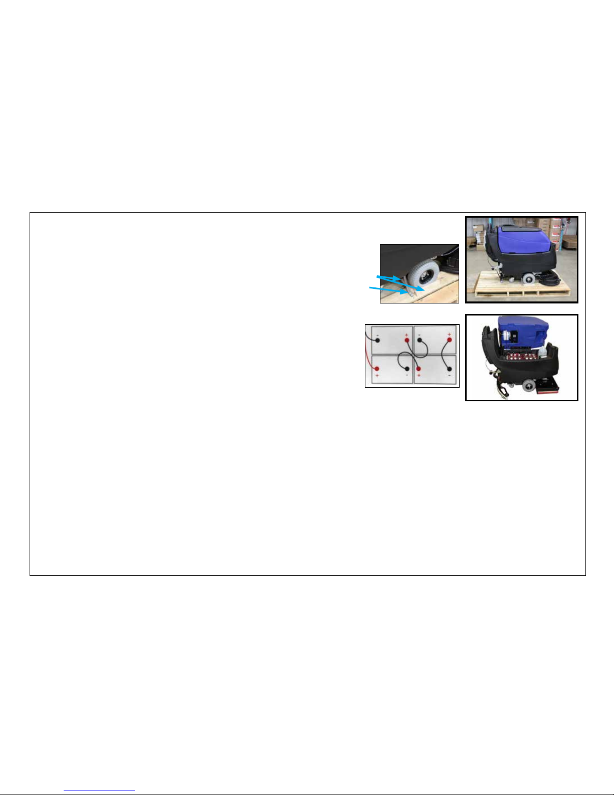
MACHINE PREPARATION
UNPACKING & BATTERY INSTALLATION
UNPACKING THE MACHINE
1. Remove the outer packaging.
2. The machine is fastened to the pallet with tie down brackets. Remove the brackets with a 3/8-inch
socket head tip in a cordless screwdriver.
3. The machine is also held in place with four cleats. Remove the cleats with a phillips tip
in a cordless screwdriver.
4. Raise the scrub head of scrubber and put it in the transport position.
5. Using a ramp, push the machine backwards down from the pallet.
5. Keep the pallet and brackets for any future transport needs.
4
BATTERY TYPE
To power the machine you can use either wet batteries or AGM batteries. Other types must not be used.
The maximum dimensions and the weight are:
Width: 7 1/8 in (181 mm)
Length: 10 3/8 in (264 mm)
Height: 11 5/8 in (295 mm)
Weight: 72 lb (33 kg)
BATTERY INSTALLATION
The machine will be supplied with a battery charger and either four 6V wet or AGM
batteries. The batteries must be housed in the battery compartment beneath the
recovery tank.
To insert batteries:
1. Lift the recovery water tank, opening it as far as it will go using the side handle.
2. The batteries must be lowered into the compartment using lifting and
transportation means suitable for the weight and dimensions.
3. They must be connected together in series, to obtain overall voltage of 24V on
the lugs.
NOTE: Fully charge the batteries before using the machine.
NOTE: Your charger must be set according to the type of battery you install. Read charging section of manual for further instructions on how
to set your charger correctly for your battery type.
Battery Connection
Diagram
Tie down bracket
NOTE: The on-board charger has been programmed to work with the batteries that Pacic Floorcare provides. Using other battery
types not specied for the S-Series mid-size scrubber by Pacic Floorcare may impair performance of the unit and will affect
the life of the batteries.
Recovery tank shown in fully
open position
Cleats
Page 5
5
MACHINE PREPARATION
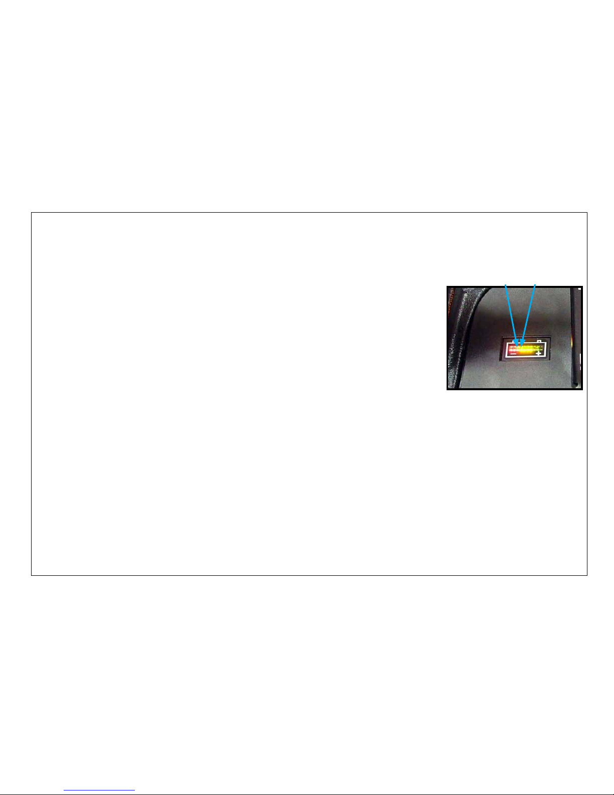
BATTERY POWER LEVEL INDICATORS
The battery power level gage is located on the upper control panel. The gage has a series of LEDs to indicate the amount of power left in the
batteries. When the batteries have a full charge, all LEDs are lit. As the batteries are discharged, the LEDs will begin to go out from right to
left. To maximize the life of the batteries, do not allow the LEDs to go beyond the discharge level as described below.
To maximize the life of the batteries, only recharge the batteries when the machine is operated for a total of 30 minutes or more and always
recharge the batteries immediately after usage when LEDs are indicating charging is required as described below.
BATTERY POWER LEVEL INDICATOR
The battery power level gage is located on the upper control panel. The gage has red, yellow and green
LEDs to indicate the amount of power left in the batteries.
On lead acid battery-equipped units, when the discharge level reaches the rst red LED, it is a good time
to nish your scrubbing application and recharge the unit. If you do choose to continue scrubbing, when
the last red LED begins to ash, the unit will shut down the brush motor but leave the vacuum and
traction drive operational to perform nal water recovery and transport back to storage. This function
not only serves as an indicator that your battery level has reached a point where recharging is required,
but also protects the batteries from being fully discharged.
AGM battery-equipped units should not be used after the last yellow LED goes out leaving only red
LEDs. Using the unit beyond this point can reduce the life of the batteries.
NOTE: The battery power level gage also displays fault codes. The LEDs will ash specic fault codes if
a fault is detected. See Troubleshooting section for LED fault codes.
Battery Level Indicator
Recharge AGM
batteries
Recharge lead
acid batteries
Page 6
6
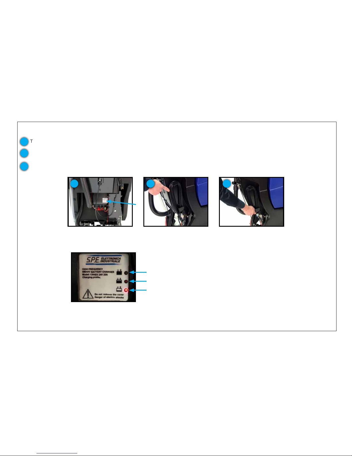
CHARGING THE BATTERIES WITH AN ON-BOARD CHARGER
Before using your S-Series mid-size scrubber for the rst time, fully charge your batteries.
MACHINE PREPARATION
USING YOUR ON-BOARD CHARGER
The on-board charger has charging indication LEDs - the red LED means it has just started the charging cycle, the yellow LED indicates that it
has reached the second phase of charging and green LED means the unit is fully charged.
Charging indication LEDs
Red indicates charge cycle has just begun
Yellow indicates charge cycle is in the second phase
Green indicates charge cycle is complete
On-board charger
1
On-board charger cord wrap
2
Quick release hook
3
These units can be equipped with an on-board charger.
1
2
3
The on-board charger is equipped with a 9 foot long cord that can be plugged directly into a 120V outlet. Do not use an extension cord.
This will void the warranty on the charger.
The cord wrap on the unit has a quick-release hook. The lower hook allows the user to slip the cord off and then the cord can be lifted off
the upper hook, all without having to unravel the entire cord.
After charging is complete, wrap the cord of your on-board charger securely to ensure the cord is not damaged.
Page 7
MACHINE PREPARATION
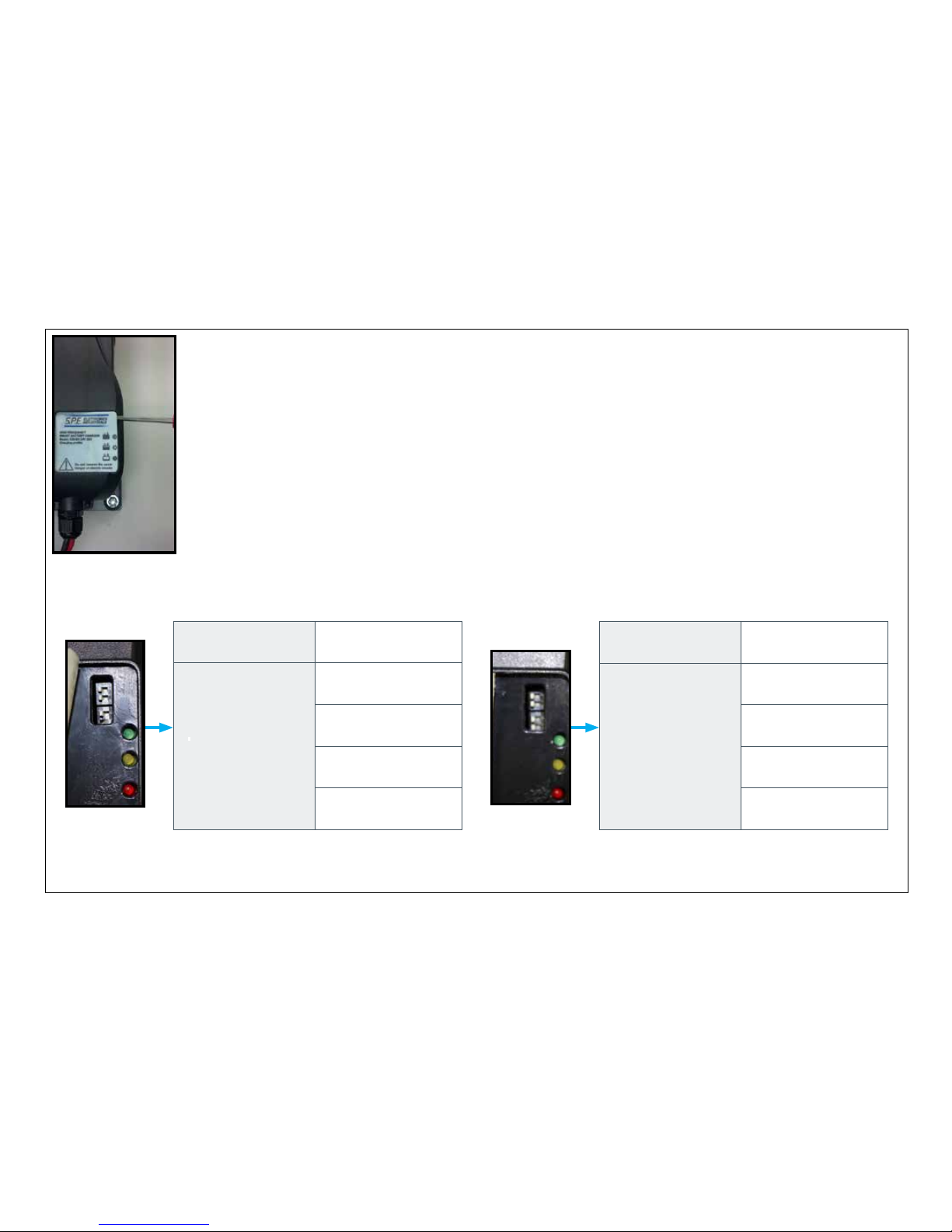
SETTING THE DIP SWITCHES ON YOUR ON-BOARD CHARGER FOR YOUR BATTERY TYPE
Both the on-board and off-board chargers are able to charge wet, lead acid or maintenance-free AGM batteries. As
your unit leaves Pacic Floorcare’s factory, the charger is set up to match the type of battery chosen in the original
machine order. Should you choose to change from the original battery type, the charger can be changed by re-setting
the dip switches.
NOTE: The on-board charger has been programmed to work with the batteries that Pacic Floorcare provides. Using
other battery types not specied for the S-Series mid-size scrubber by Pacic Floorcare may impair performance of the
unit and will affect the life of the batteries.
To access the dip switches, use a small screw driver to lift the corner of the label on the on-board charger and peel back
partially to reveal them. Set the dip switches as shown below for the specic battery type being used in your machine.
7
Use small screw driver
to lift label off charger
BATTERY TYPE
871301 TROJAN
260AH LEAD ACID
DIP SWITCHES
OFF
(L)
OFF
(L)
OFF
(L)
ON
(R)
BATTERY TYPE
FULL RIVER
250AH AGM
DIP SWITCHES
OFF
(L)
OFF
(L)
OFF
(L)
OFF
(L)
Page 8
8
MACHINE PREPARATION
USING YOUR OFF-BOARD CHARGER
CHARGING THE BATTERIES WITH AN OFF-BOARD CHARGER
Before using your S-Series mid-size scrubber for the rst time, fully charge your batteries.
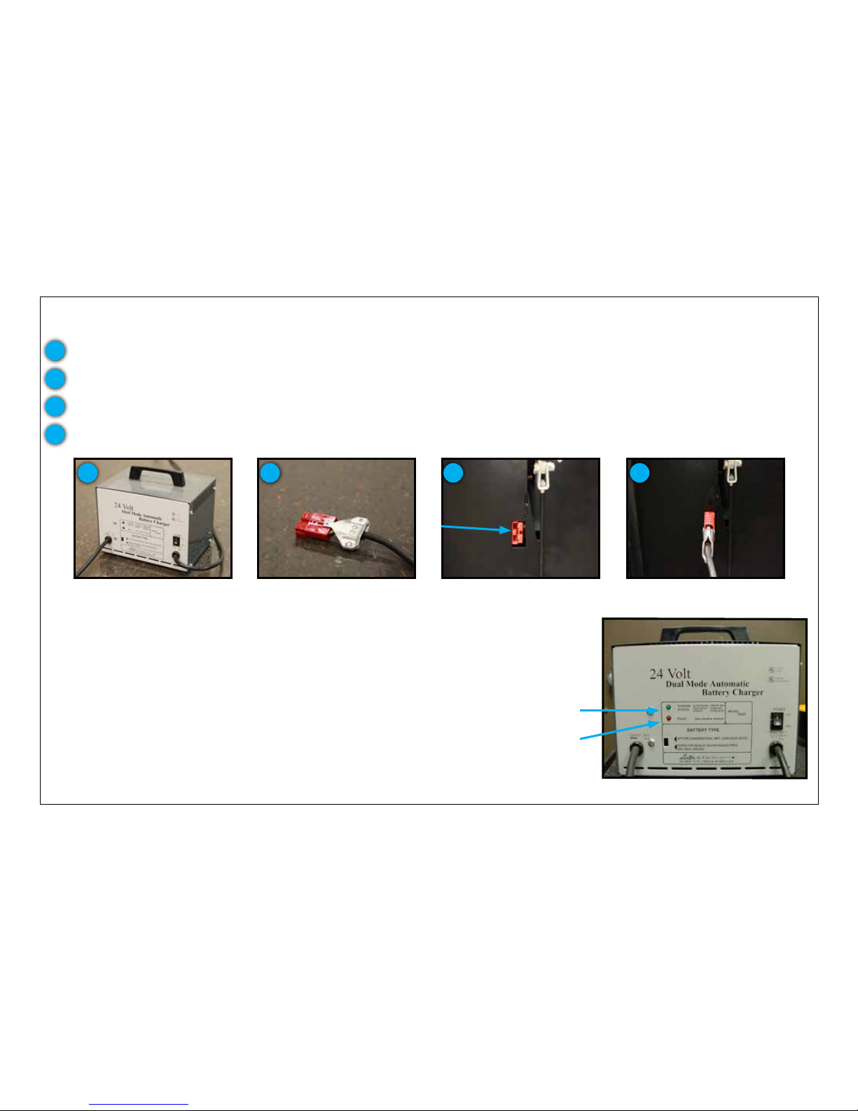
Anderson connector located on
lower, rear panel
Anderson connector located on
charger cable
Off-board charger
The off-board charger has charging indication LEDs. The primary LED is
green and if blinking slowly, then the batteries are still below 80% of full
charge. If blinking fast, then the batteries are above 80% of full charge while
if solid green, the batteries are fully charged. There is a red “fault” LED
as well. In the rare occurence that this LED comes on, check the charger
operator manual for troubleshooting guidance.
Charger connected to machine
Charging indication LEDs
(charger appearance may vary)
Primary indicator light
Fault light
1 2 3 4
1
2
3
These units can be equipped with an off-board charger.
There is also an Anderson connector on-board the S-Series mid-size scrubber located on the lower control panel at the rear of the
machine.
With the 120V cord plugged into the wall, connect the two Anderson connectors and the batteries to begin charging.
4
The off-board charger has both a standard 120V power cord and a cord with an “Anderson connector”.
Page 9
MACHINE PREPARATION
SETTING THE DIP SWITCHES ON YOUR OFF-BOARD CHARGER FOR YOUR BATTERY TYPE
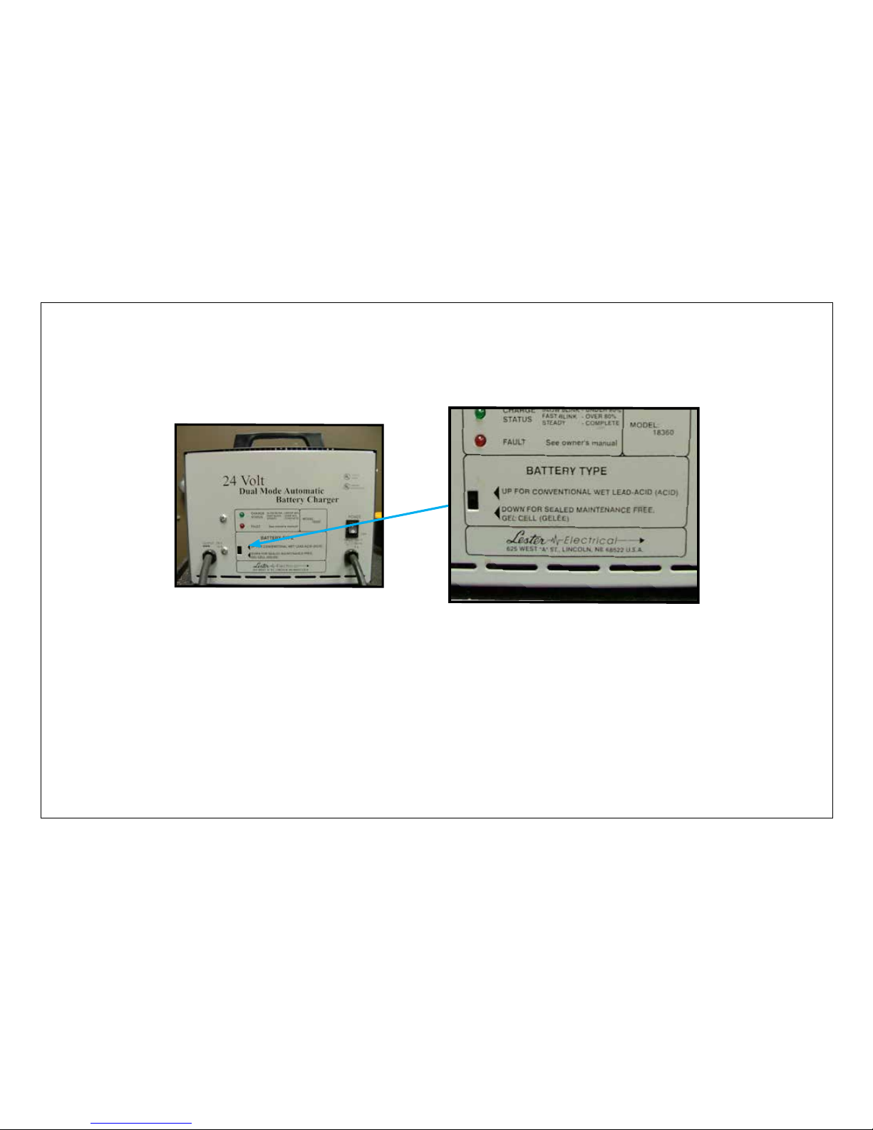
The off-board charger is able to charge wet, lead acid or maintenance-free AGM batteries. As your unit leaves Pacic Floorcare’s factory, the
charger is set up to match the type of battery chosen in the original machine order. Should you choose to change from the original battery
type to the other, the charger can be changed by re-setting the dip switch.
To re-set the dip switch, slide the switch up for wet, lead acid batteries (battery part number 871301) or down for sealed,
maintenance free AGM batteries (battery part number 871302).
9
Front view of off-board charger
(charger appearance may vary)
Close up of dip switch
Page 10
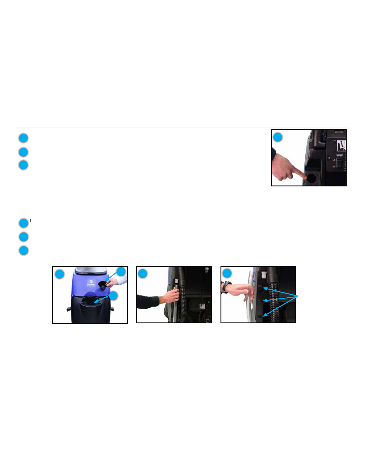
It is easy to gage the solution level by watching the fog-free solution sight gage at the rear of the
machine. Additionally, marks on the tank provide solution level indicators as a guide.
10
To prepare the machine for cleaning, the unit must be lled with cleaning solution.
Rear hose ll port
NOTE: Always use low-foam detergent. Introduce a small amount of defoaming liquid in the recovery tank
before starting work to prevent foam from being generated. Never use pure acids.
MACHINE PREPARATION
SOLUTION TANK
1
2
1
Water and cleaning agent can be added to the S-Series mid-size scrubber’s rear hose ll port located to
the left of the control panel.
Liquid detergent should be added to the tank in the concentration and manner specied by the
manufacturer for an twenty two (22) gallon solution tank. The formation of excess foam could damage the
vacuum motor, so be sure to use only the correct amount of detergent. Water temperature should not
exceed 120°F (50°C).
Sight gage hose
4
4
6
The sight gage hose performs double-duty as the solution drain hose as well. You simply slide the
hose off the press tting and lower the hose to a drain or mop sink.
Sight gage hose released from
press tting
6
Solution level indicators
5
The bottom of the front ll port is also a full level indicator. Once you are able to see water at the base
of the opening, you have reached the full level.
3
There is also a front ll port that is able to accept hose or bucket lling.
The S-Series mid-size scrubber comes equipped with a ll port strainer to block debris from falling into
the solution tank.
Front ll port
2
5
3
Page 11
11
MACHINE PREPARATION
SOLUTION TANK - AUTO-OFF SOLUTION FILL SYSTEM OPTION
1
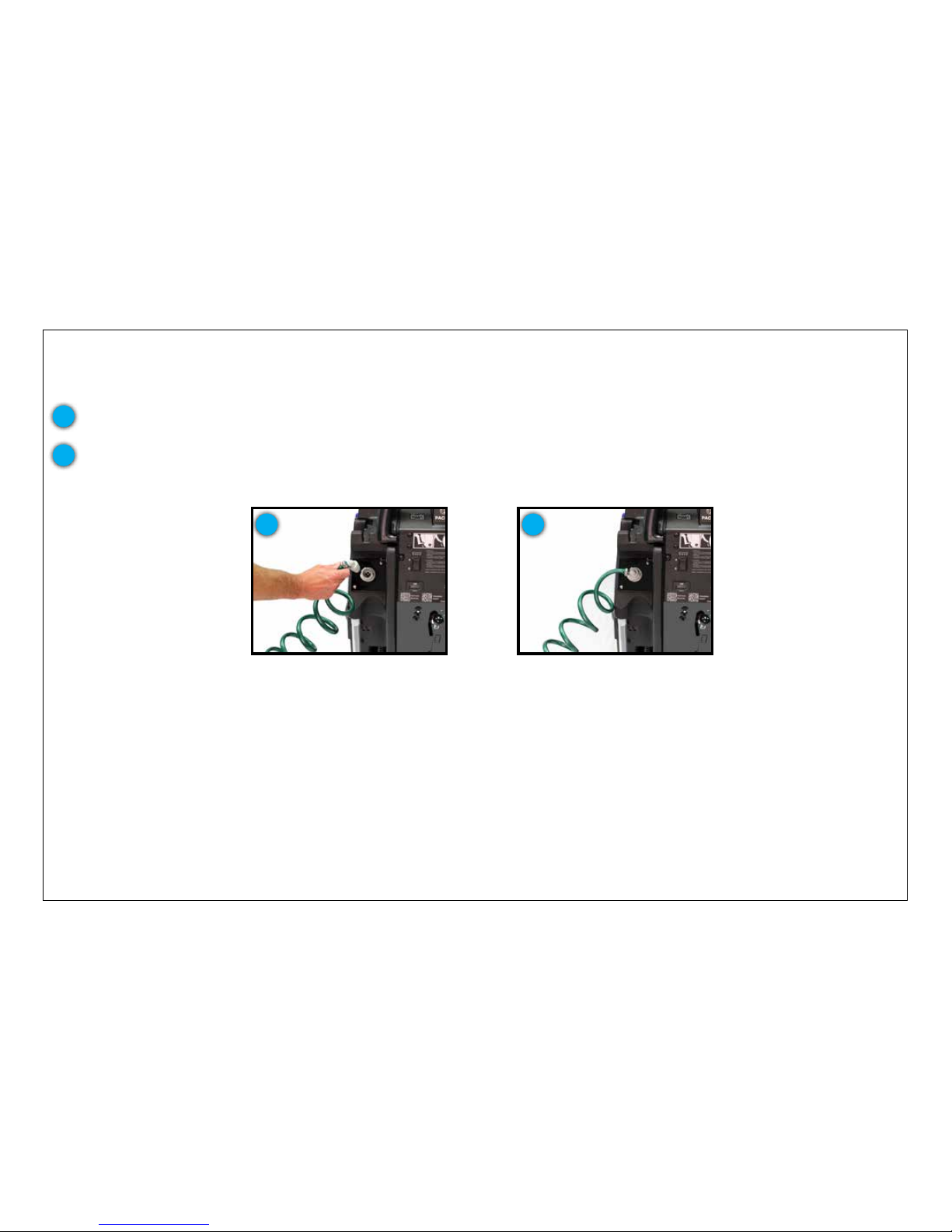
If your machine is equipped with the auto-off solution ll system option, connect the male end of the quick-connector to your 1/2-inch inner
diameter ll hose. Once your ll hose is set up, leave the faucet for that hose open - the connector will act as a stop.
Auto-off solution ll system
connected to scrubber
2
Male quick-connect shown on ll
hose
1
2
When it is time to ll your machine, click the hose onto the female quick-connector at the back of the machine and the unit will begin
to ll with water.
Once the machine is full, the automatic ll port will shut off the water ow. Then just disconnect the hose and you are ready to add
detergent.
Page 12
12
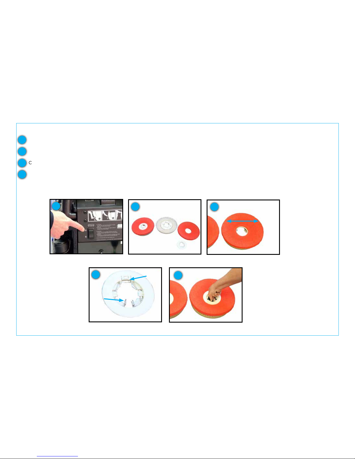
Connect the cleaning pad to the disk pad drivers by centering them on the drivers.
MACHINE PREPARATION
ATTACHING CLEANING PADS TO YOUR PAD DRIVERS - DISK HEAD
Depress position “A” for 1 second
then depress position “B”
1
If using oor pads with your pad drivers:
1
2
3
Place your pad drivers on a work surface and remove the center lock tting from the pad drivers. To do so, squeeze the center lock wires
inward and lift the center lock off the pads.
Remove the pad drivers by locating the automatic off switch on the lower control panel at the rear of the machine. Depress position “A”
for 1 second and then depress position “B” to “click-off” the pad drivers.
4
Squeeze center lock wires inward and press center lock down, tab side rst, compressing the pad and then release the wires so that they
lock in place holding the pad. Repeat for the other pad driver.
NOTE: The S-Series pad drivers are tufted pad drivers. Do not use a pad driver on the oor without a pad in place. This will cause damage
to your oor.
Disconnect center lock tting & lay
next to the pad driver
Center pad on pad driver
Squeeze center lock wires inward,
press down onto pad & release wires
2
3
4
Close up showing center lock tab &
wires
4
wires
tab
Page 13
13
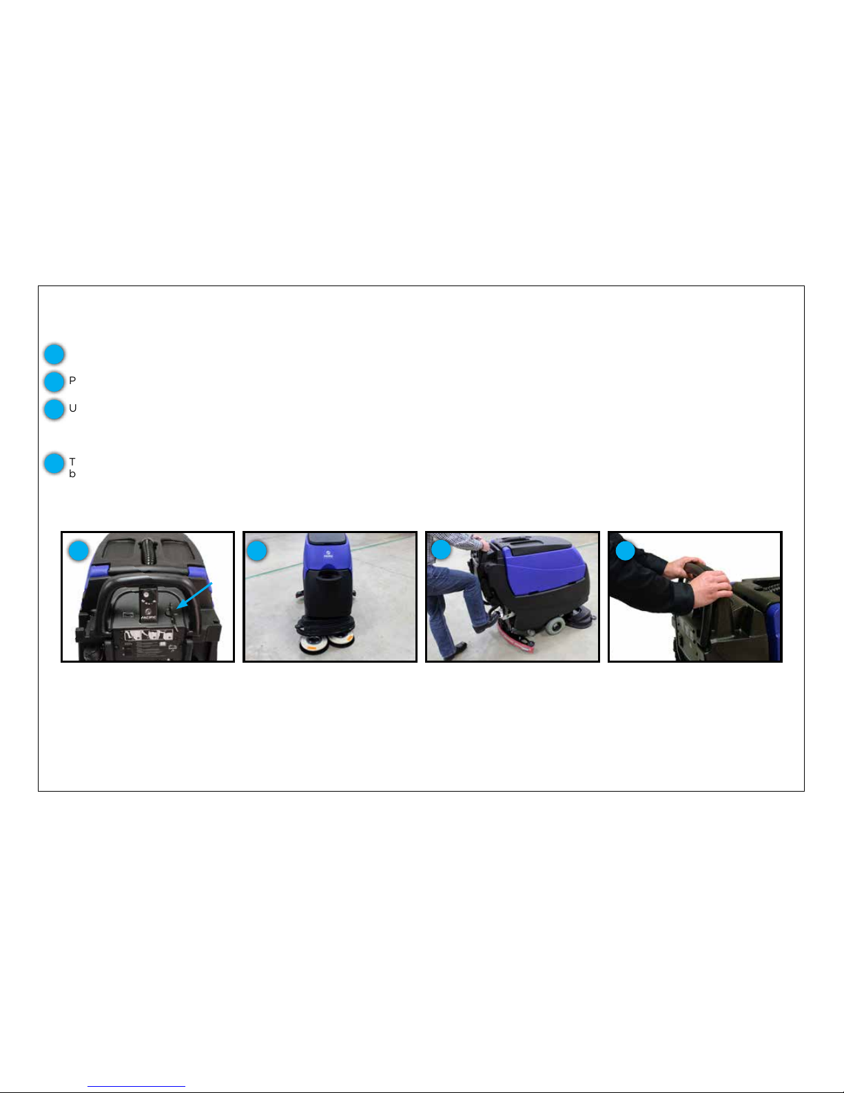
The pad drivers or brushes are attached by using the automatic on/off system. This valuable ingenuity removes the need for operators to
kneel or strain to attach the pad drivers or brushes.
First, start by placing the pad drivers or brushes on the oor in front of the S-Series mid-size scrubber.
Quickly pulse the activation trigger
Position scrub head over pad
drivers or brushes
MACHINE PREPARATION
ATTACHING YOUR PAD DRIVERS OR BRUSHES TO THE S-SERIES MID-SIZE SCRUBBER - DISK HEAD
Lower the scrub head using the
foot pedal
Turn unit on using key switch
Turn the unit on using the power key switch.
Push or drive it into position so that the unit’s scrub head is centered over the pad drivers or brushes.
Utilize the foot pedal to lower the scrub deck down onto the pad drivers or brushes by depressing the pedal while shifting it to the right.
Once clear of the lower notch, lifting your foot will lower the scrub deck. Make sure that the shroud completely covers the pad drivers or
brushes in the lowered position. Should the shroud be resting on a portion of the pad drivers or brushes, the head isn’t centered and will
not attach properly.
The operation is completed by quickly pulsing the activation trigger. This will “click on” the pad drivers or brushes. If the pad drivers or
brushes do not quickly engage, do not continue pressing the activation trigger. Realign the scrub deck and try procedure again. When
you have the scrub deck aligned properly, you should see a noticeable drop of the scrub deck when lowered and the bristle skirt on the
shroud should almost be touching the oor.
1
2
3
4
1 2
3
4
Page 14
14
ATTACHING A PAD TO YOUR ORBITAL PAD DRIVER
The orbital unit can be used for daily cleaning; however it specializes in chemical-free nish removal for low-cost nish maintenance
programs. The following directions show how to prepare the machine for both applications.
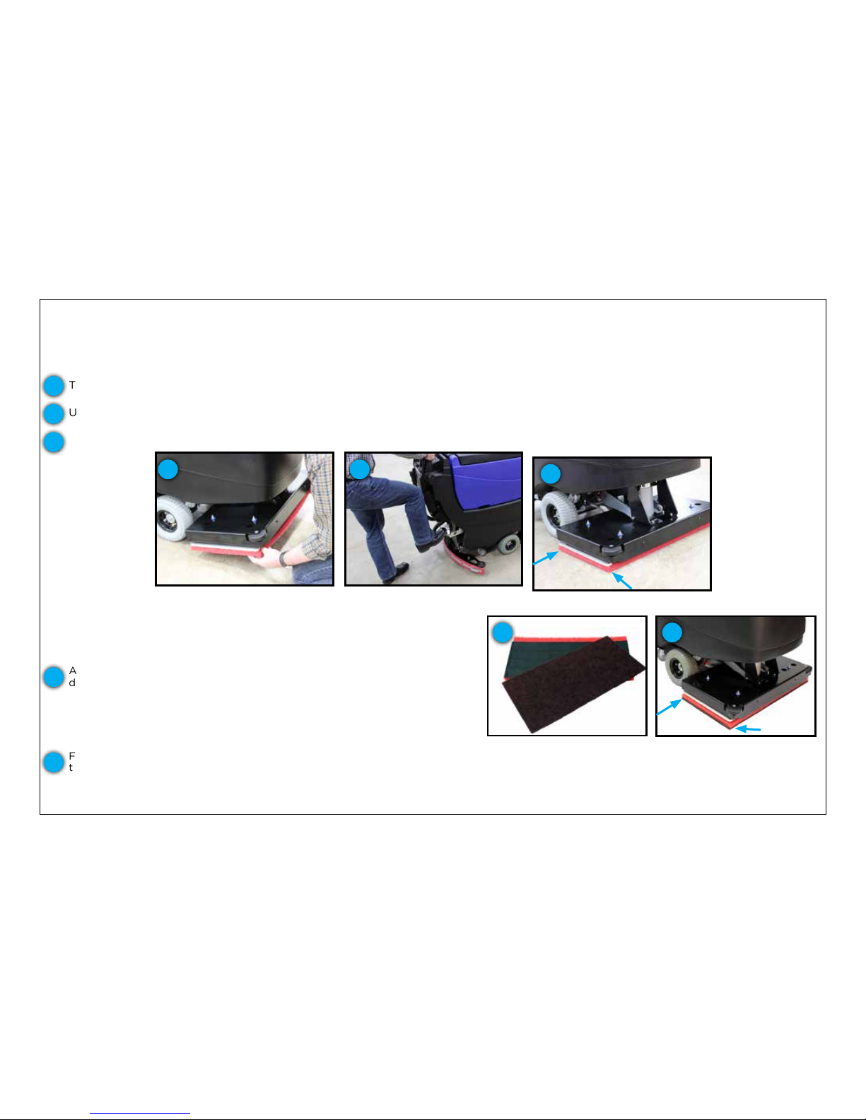
For cleaning, the orbital unit is t with a rectangular, 28 in (711 mm) x 14 in (356 mm) pad. The head comes standard with a rectangular pad
drive plate with a Mighty-Lok® connection system.
MACHINE PREPARATION
ATTACHING YOUR PAD - ORBITAL HEAD
Red backer pad & Velcro pad
retainer (black) alignment
shown above with surface prep
pad (brown) pulled away
Align the front corners of the pad
and press to adhere
Proper alignment of pad
Lower the scrub head using the
foot pedal
For chemical-free nish removal, it requires the addition of a specialized surface
preparation pad. The application still requires the attachment of a traditional
cleaning pad rst. This pad acts as a “backer pad” which compensates for low
and high spots in the oor.
Proper alignment of pad
To attach the pad, align the front corners of the pad to the front corners of the orbital drive plate and press to attach.
Use the foot pedal to lower the scrub deck down onto the pad ensuring alignment from front-to-back and side-to-side.
When the head is properly set onto the pad, you are ready for cleaning.
1
2
3
1 2
3
4 5
Align the Velcro pad retainer along one length of the red, backer pad and press
down. This will leave a 2” gap along one side of the backer pad. Then place
the surface prep pad on top of the pad retainer, centering it from front-to-back
& side-to-side with the red pad. The 2” gap left by the pad retainer needs to be
at the front of the machine so that water can fully saturate the pad. Align your
pad assembly with all corners of the pad driver and press upward. The red
backer pad should be in closest contact with the pad driver.
Finish the operation by using the foot pedal to lower the scrub deck down onto
the surface preparation pad, once again ensuring alignment from front-to-back
and side-to-side. When the head is properly set onto the pad, you are ready
for your nish maintenance program.
4
5
Page 15
15
MACHINE PREPARATION
CONNECTING THE SQUEEGEE AND ADJUSTING SQUEEGEE HEIGHT
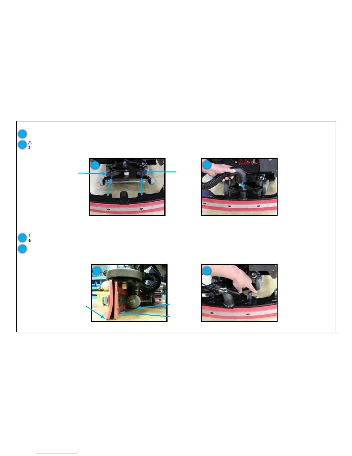
Prior to shipping from the factory, the squeegee assembly is removed from the unit. To connect your squeegee assembly to the machine:
The squeegee blade assembly height is factory set at the optimum water recovery position with the squeegee wheels being
approximately 1/32 inch (1 mm) off the ground allowing the recovery blade to deect as shown below.
Button screw to raise and lower
squeegee assembly wheels
Align the squeegee assembly retention slots with the easy-grip knobs then tighten until secure.
Attach the recovery hose to the squeegee assembly neck. Make sure to route the hose so that it won’t interfere with the swing of the
squeegee assembly.
Close up of squeegee assembly and
blade deection
Proper recovery
blade deection
Slight clearance
off of oor
No clearance
off of oor
1
2
3
4
3 4
If for some reason your squeegee blade height must be adjusted, it is done so by turning the left button screw located on the squeegee
frame assembly clockwise to raise the left squeegee wheel and counter-clockwise to lower the wheel. The same is true for the right
button screw/squeegee wheel.
After aligning assembly, tighten the
easy-grip knobs and attach the
recovery hose
2
Positioning the squeegee assembly to
mount onto the squeegee frame
1
Easy-grip
knob
Easy-grip
knob
Page 16
16
MACHINE PREPARATION
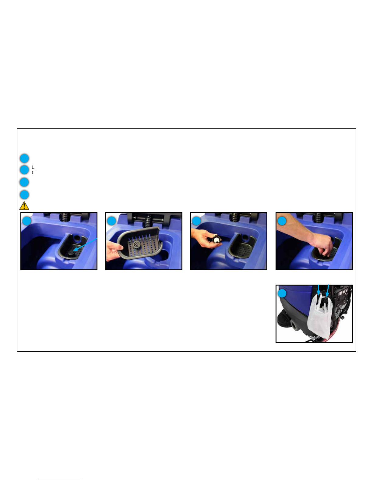
RECOVERY TANK PREPARATION & PLASTIC BAG HOLDER
PICKING UP LARGER DEBRIS DURING THE CLEANING PROCESS
Your S-Series mid-size scrubber has been designed with two hooks molded into the handle that can be
used to hang a plastic bag to put larger pieces of debris that you come across during the cleaning process
or that obstruct the squeegee assembly and cause streaking. Simply slide a handle of the plastic bag over
each of the hooks.
Plastic bag hooks indicated above
1
TREATING YOUR RECOVERY TANK
Your S-Series mid-size scrubber has been designed with a debris tray and the TTS tank treatment system. TTS is a treatment system that
utilizes Bromine tablets, typically used in pools and spas, to kill the bacteria in the tank that cause odors. To ensure that TTS is prepared to
treat your recovery tank:
Check the TTS bromine puck
3
Press the TTS holder and bromine
puck back into the debris tray
4
TTS is located in the debris tray
inside the recovery tank
1
Lift the recovery tank lid to the open position and locate the debris tray.
1
Lift the debris tray out and turn it over so that you are able to pinch the two tabs protruding from the underside of the debris tray
together to release the TTS Bromine puck holder.
2
Remove the debris tray
2
Check the size of the Bromine puck. Replace the Bromine puck when it is approximately 25% of it’s original size.
3
Press the TTS holder and bromine puck back into the debris tray.
4
CAUTION: Use Bromine only! Do not use chlorine. Chlorine can interact with ammonia based detergents to cause harmful fumes.
Page 17
17
MACHINE OPERATION
OPERATIONAL CONTROLS
The machine operation and controls were designed to minimize operator training and decrease the need for adjustments during
operation. Additionally, once in operation, Pacic Floorcare’s goal was to provide an ergonomic, easy to use system. Due to this focus, the
S-Series mid-size scrubber’s key operational controls are all within reach so that the operator doesn’t have to remove their hands to perform
the operation - a key to safe, trouble-free, highly productive cleaning.
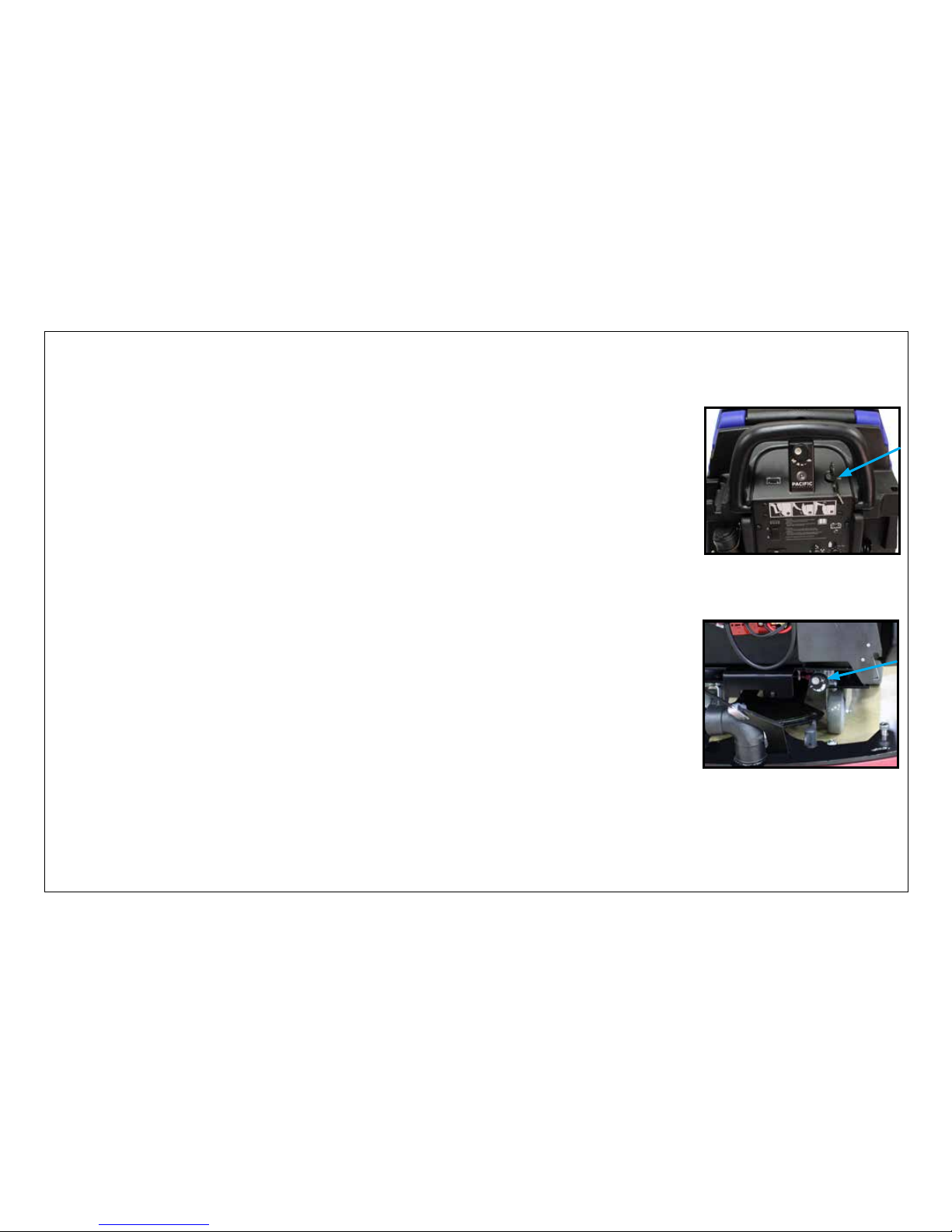
TURNING THE UNIT ON/OFF
The machine is powered on through a key switch on the upper control panel. Turn the key to the ON
position. You will see the battery meter on the left side of the upper control panel light up to show the
battery charge level.
The key switch is a proven way to eliminate unwanted operation. Simply remove the key and safely store it
away when you have completed scrubbing.
S-Series key switch
SETTING DESIRED SOLUTION FLOW RATE
For units that aren’t equipped with a chemical injection system, the next step is to set the unit to the
desired solution ow. This control feature is located at the lower rear of the machine and can be adjusted
from low to high ow spanning a range of 0 to .55 gallons (0 to 2.1 L) per minute.
Solution ow adjustment knob
Page 18
MACHINE OPERATION
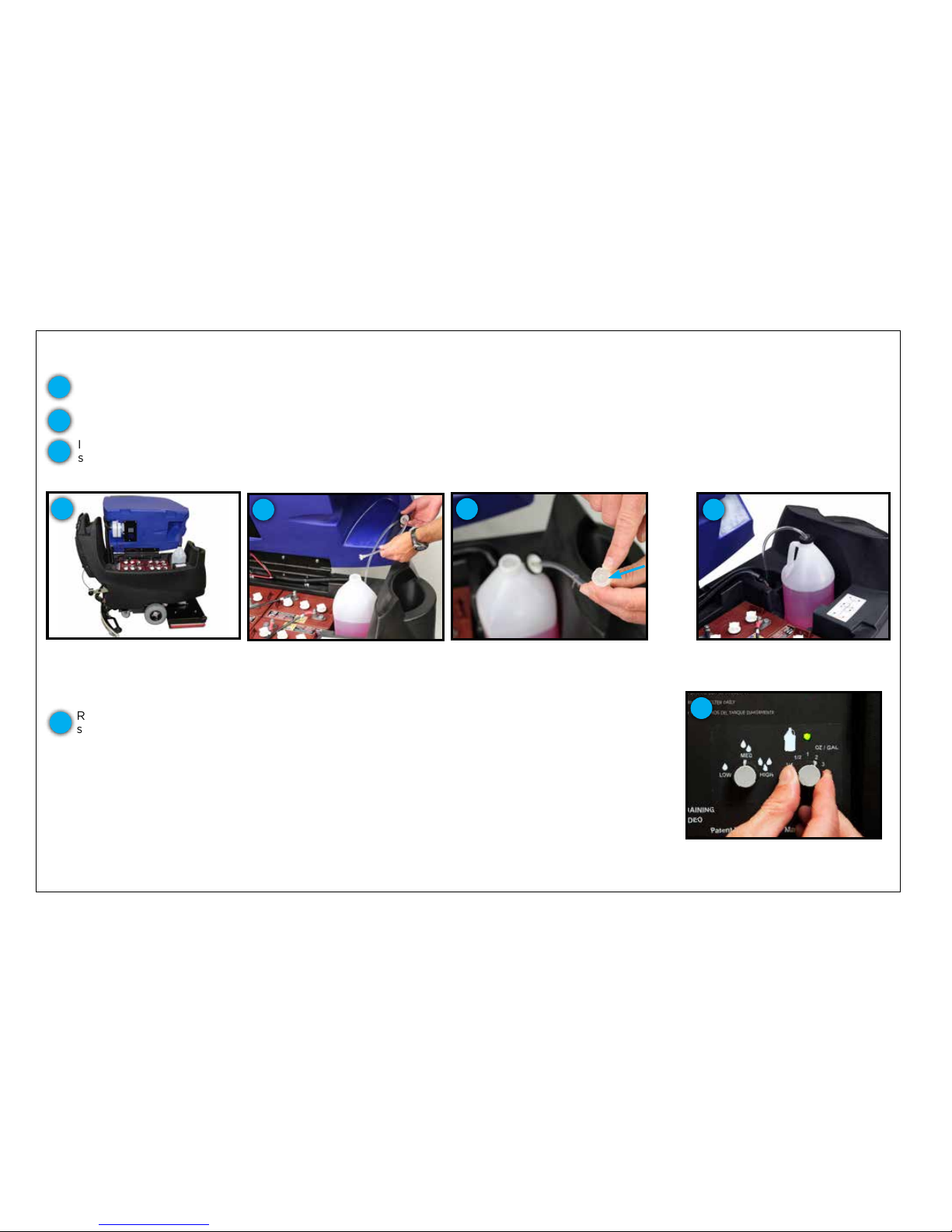
ON-BOARD CHEMICAL INJECTION SYSTEM
If your S-Series mid-size scrubber is equipped with the on-board chemical injection system, the following instructions will walk you through
the easy process of setting up and operating this system.
Chemical injection chemical mix
ratio dial being set
Lift the recovery water tank, opening it as far as it will go using the side handle.
Review the chemical’s prescribed mix ratio in ounces per gallon and then set the dial on the
scrubber’s lower control panel to match. There are 12 settings on the dial (including off), but if you
don’t see a match, use the one that most closely matches the chemical’s suggested mix ratio.
1
4
4
Recovery tank shown in fully open
position
1
Place your 1-gallon chemical container in the holder inside the machine’s battery compartment and remove the cap. The chemical holder
will accept round, square or rectangular shaped containers.
2
Insert the chemical injection system’s leader hose into the container, ensuring that the end is resting on the bottom of the container, and
screw down the system’s universal cap.
3
1-gallon chemical bottle in holder,
preparing to insert leader hose
2
Close up of leader hose
3
Strainer
on
leader
hose
Chemical bottle connected properly
to chemical injection system
3
Once the container is in place, it is time to set your mix ratio on the control panel.
18
Page 19
MACHINE OPERATION
ON-BOARD CHEMICAL INJECTION SYSTEM
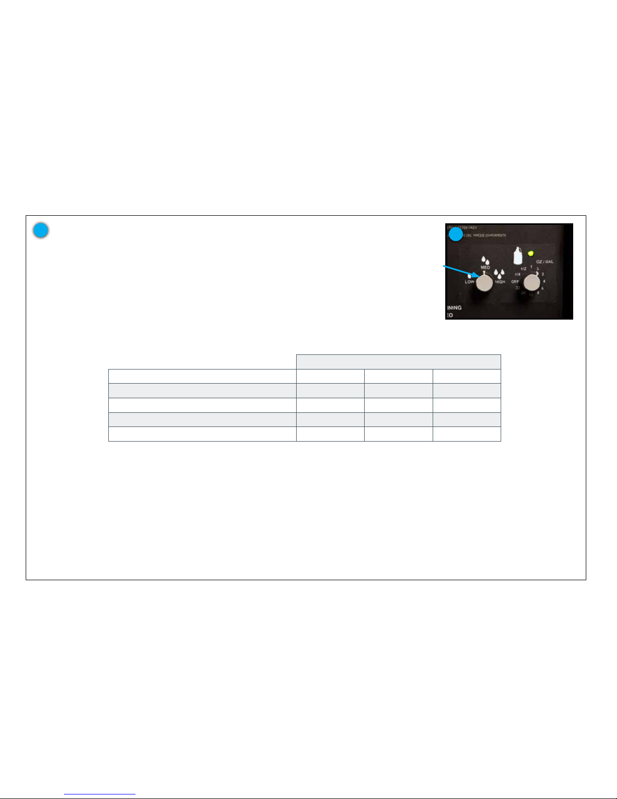
Once the chemical mix ratio is selected, set your desired solution ow rate to low,
medium or high based on your cleaning needs and the chemical injection system will
automatically mix your chemical for you. A solid green LED indicates the system is
powered and working properly.
4
19
Close up of chemical injection
system dials
4
Solution ow
rate dial
NOMINAL WATER FLOW (GPM/LPM)
HEAD SIZE & TYPE LOW MED HIGH
24-inch (610 mm) dual disk .1 gal (.38 l) .26 gal (1 l) .48 gal (1.8 l)
28-inch (711 mm) dual disk .12 gal (.45 l) .3 gal (1.1 l) .56 gal (2.1 l)
28 x 14-inch (711 x 356 mm) orbital .12 gal (.45 l) .3 gal (1.1 l) .56 gal (2.1 l)
32-inch (813 mm) dual disk .14 gal (.53 l) .35 gal (1.3 l) .6 gal (2.3 l)
To purge an old detergent, set the detergent to the highest chemical mix ratio and run until the leader hose line is empty.
If the detergent is not priming, temporarily set the detergent to a higher setting until detergent appears on the oor.
*Flow tolerances are approximately plus or minus 20%
Page 20
20
MACHINE OPERATION
OPERATIONAL CONTROLS
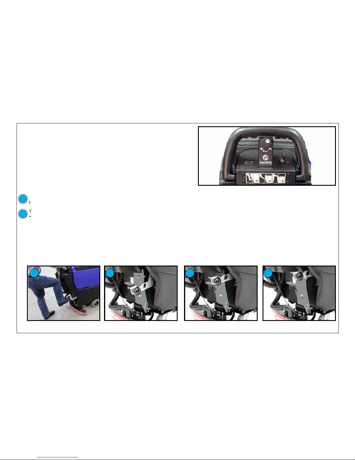
Once the machine is powered on and the solution ow is set, it takes three
simple steps to operate the machine: lower the scrub deck, lower the
squeegee and engage the activation trigger. These steps are visually shown
on the lower control panel by the S-Series mid-size scrubber’s “1, 2, 3-Step”
on-board operation guide. Following are the detail steps of how scrubbing
and recovery functions are activated.
On-board “1, 2, 3-Step” operation guide
LOWERING THE SCRUB DECK
The scrub deck is lowered using the foot pedal at the rear of the unit.
Lowering scrub head using foot
pedal
Lower down pressure setting
Place your foot on the pedal and depress the lever while shifting it to the right. Once clear of the lower notch, lifting your foot will lower
the scrub deck into the operating position.
The S-Series mid-size scrubbers have three down pressure settings.
• The 24-inch (610 mm) disk unit has settings of 50, 100 & 140 lb (23, 45 & 64 kg)
• The 28-inch (711 mm) & 32-inch (813 mm) disk scrubbers have settings of 70, 110 & 150 lb (32, 50 & 68 kg)
• The 28-inch (711 mm) orbital scrubber has settings of 70, 110 & 160 lb (32, 50 & 73 kg)
When the unit is set into operating position with the foot pedal, it is in the lower down pressure position. This position is typically used
for daily cleaning of normal soils. However, should you have tough soils or want to perform chemical-free nish removal, you can engage
higher down pressure settings. To engage the medium down pressure setting, lift the foot pedal lever so that the hook is secured in the
cutout in the foot lever. To engage high down pressure, lift the foot lever to the upper notch position so that the bottom of the lever is
locked on the hook of the bracket. To disengage medium or high down pressure, simply lift and shift the lever to the right and lower into
normal operating position.
1
2
1 2
High down pressure setting when
lever is lifted to top position
2
Medium down pressure when lever
is hooked in mid-position
2
Page 21
21
MACHINE OPERATION
OPERATIONAL CONTROLS
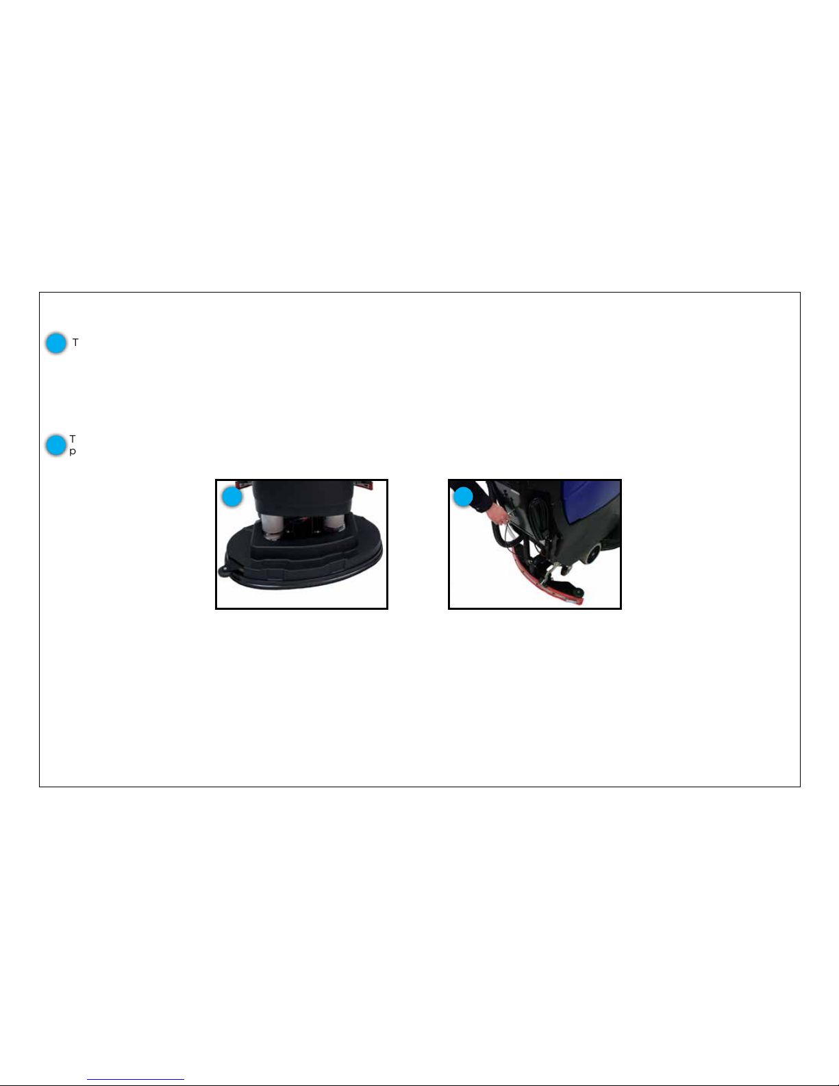
LOWERING THE SCRUB DECK
The scrub deck is lowered using the foot pedal at the rear of the unit.
Self-adjusting head shroud with
bristle skirt
The disk scrub head is equipped with a self-adjusting shroud with bristle skirt that virtually eliminates overspray and increases ease of use.
3
3
To lower the squeegee, lift the squeegee lever and shift it left to clear the notch. Once clear, lower the squeegee into the recovery
position. In doing so, the S-Series mid-size scrubber’s vacuum motor will activate.
4
LOWERING THE SQUEEGEE
Lowering the squeegee assembly
4
Page 22
22
MACHINE OPERATION
OPERATIONAL CONTROLS
ACTIVATING THE SCRUBBER
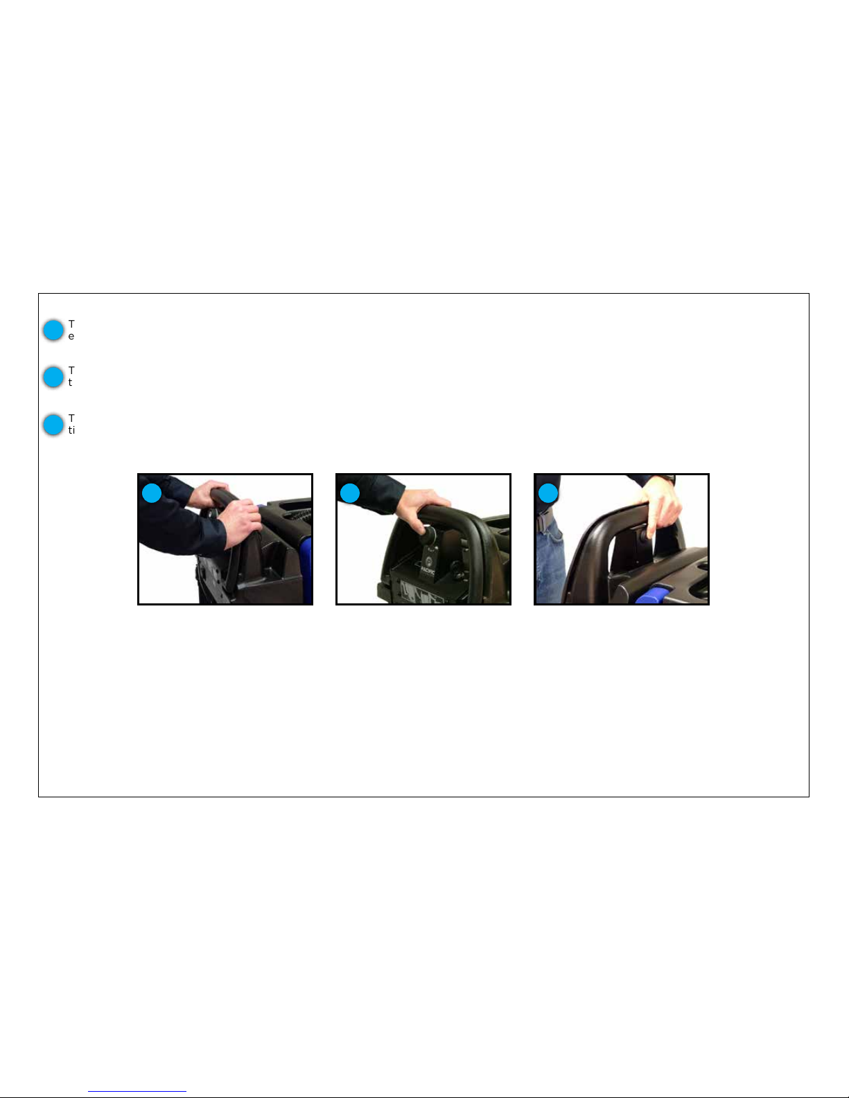
Activating the handle trigger Speed control adjustment
Reverse switch is easily reached
with ngertip
To begin scrubbing, engage the handle trigger. The trigger activates solution ow, the brush motor and traction drive. This unique,
ergonomic design accommodates different operator heights by allowing the user to activate the trigger from any position on the
handle.
The speed control and reverse switch are purposely located so that the operator doesn’t have to let go of the machine with either hand
to perform the function. Speed control is easily thumb adjusted and the reverse can be depressed with your ngers on the back side of
the control housing.
This one-handed reverse feature allows the operator to lift the squeegee with the other hand – a small element with big rewards when in
tight spaces.
1
2
3
1 2 3
Page 23
23
MACHINE OPERATION
OPERATIONAL CONTROLS
TRANSPORT MODE
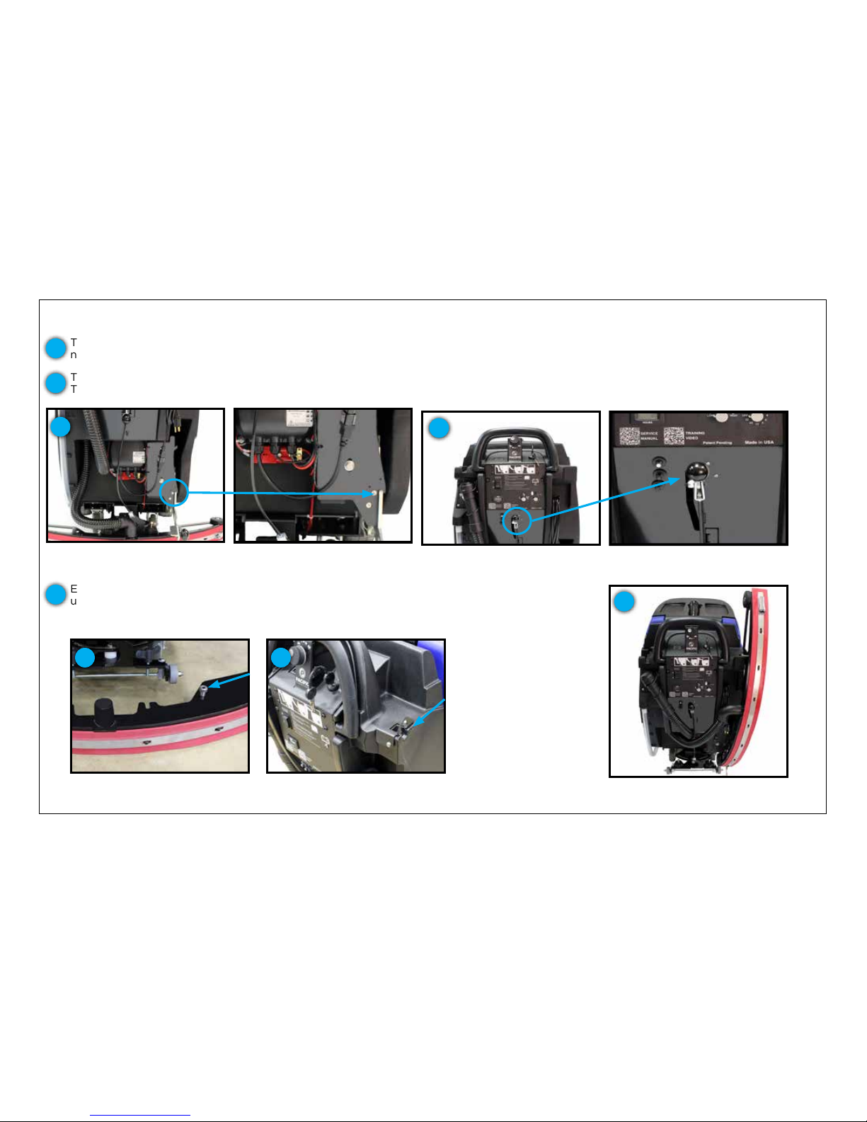
The scrub deck and squeegee must be in the raised position for transport.
Squeegee assembly in raised/
storage position
The scrub deck is raised into transport position by placing your foot on the foot pad and depressing the lever until it clears the lower
notch. Once clear, shift the lever to the left and place it into the lower notch.
To raise the squeegee, lift the squeegee lever high enough to clear the notch, shift it to the right and lower it into the resting position.
The vacuum fan will continue to run for 10 seconds in order to evacuate the recovery hose.
1
2
2
Scrub deck in transport/storage
position
1
Squeegee assembly in transport
position
3
Easily transport machines in, out or through facilities with the S-Series mid-size scrubber’s
unique squeegee hanger feature. Simply remove the squeegee assembly (see Page 14) while
leaving the recovery hose attached, lift the squeegee to a vertical position on the right side of
the machine and place the squeegee tab into the squeegee hanger.
3
Squeegee hanger tab
3
Squeegee hanger recess on
scrubber
3
Page 24

MAINTENANCE
SCHEDULE FOR SERVICE
MAINTENANCE DA I LY WEEKLY MONTHLY
EVERY SIX
MONTHS 100 HOURS 200 HOURS
Clean squeegee assembly. Check blades for wear or damage. Check if
adjustment needed to squeegee height
X
Clean out recovery tank inside and out and oat shut off assembly.
Check both for damage. Leave recovery tank open during storage
X
Empty and clean out debris tray in the recovery tank
X
Empty any debris from front ll port strainer
X
Clean pads / brushes and check for wear or chemical build up
X
Check handles, knobs and switches for damage
X
Charge batteries (if machine used longer than 30 minutes)
X
Check hoses for wear, blockages or damage
X
Check on-board chemical container level (if scrubber is equipped with
on-board chemical injection system)
X
Clean outside of solution tank and clean inline solution lter. Check both
for damage
X
Check wet battery water level and add distilled water if necessary
X
Check splash guard around scrub head for damage (disk models only)
X
Thoroughly clean entire machine
X
Check Bromine puck in TTS. Replace if it’s 25% of it’s original size
X
Visually inspect HEPA lter
X
Check linkages and connectors for wear / damage
X
Check all bearings and wheels for noise or loose hardware
X
Check recovery tank lid gasket for wear or damage
X
Check batteries for cracks, corrosion or signs of overheating
X
Check all screws and nuts. Tighten if necessary
X
Inspect isolators (orbital units only)
X
Check for loose wires or connections
X
Clean batteries and terminals
X
Blow out dust in motors
X
Clean pivot points on squeegee and scrub deck linkages
X
NOTE: With regular maintenance, the lifetime of your machine and its safe operation are extended and ensured. Scheduled maintenenace should be
performed by qualied personnel or by an authorized service center.
WARNING:
These maintenance procedures must be performed with the machine off and the batteries disconnected. Make sure to read all safety
instructions prior to performing maintenance.
Page 25
25
MAINTENANCE
END OF SHIFT
Once you’ve completed your daily scrubbing, project work or nish maintenance, proper end of use maintenance can greatly extend the
machine’s life, improve performance, enhance sanitization and lower the machine’s long-term operational costs. There are four key areas we
will review and demonstrate: the recovery tank, squeegee assembly, battery maintenance and charging, ending with pad and brush
maintenance.
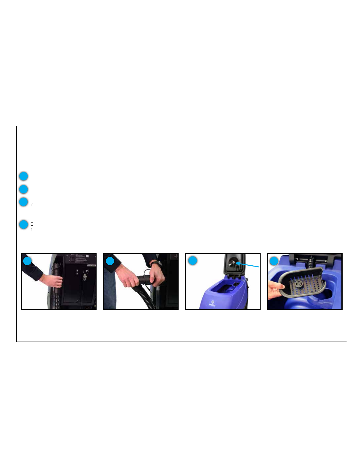
RECOVERY TANK
At the end of the job, the recovery tank needs to be emptied and rinsed out. To drain the recovery tank, utilize the recovery tank drain hose
at the rear of the machine.
Recovery tank drain hose
Drain hose has a press-t cap and
restriction collar
Vacuum mesh lter screen and ball
oat system indicated above
Empty debris tray and clean out
The drain hose has a press-t cap that is removed for the draining process.
1
The hose is also equipped with a restriction collar that can be bent or squeezed to reduce splashing and spraying during the operation.
As the recovery tank drains, lift the recovery tank lid to the fully open position. When almost empty, begin to rinse out the sediment
from the bottom of the tank with a clean water hose. After the tank is thoroughly rinsed and drained, leave the tank lid open to dry. This
is a great time to inspect and clean the vacuum mesh lter screen and ball oat system. This can be removed for cleaning by
unscrewing the lter screen and rinsing it with a hose or faucet.
Empty and clean the debris tray after every use. Operating the machine without the debris tray can lead to a clogged outlet hose or
facility drain
The full access tank is designed for periodic deep cleaning and sanitizing. Once thoroughly rinsed, the operator can use a cleaner and
sanitizer with a cloth or sponge to completely sanitize the recovery tank. This reduces the mold and mildew that can form over time.
2
3
4
1 2
3
4
Page 26
26
MAINTENANCE
END OF SHIFT
SQUEEGEE ASSEMBLY
The squeegee system is crucial to high-performance cleaning. It is the last thing that touches the oor so proper maintenance is important
for making it perform at its peak.
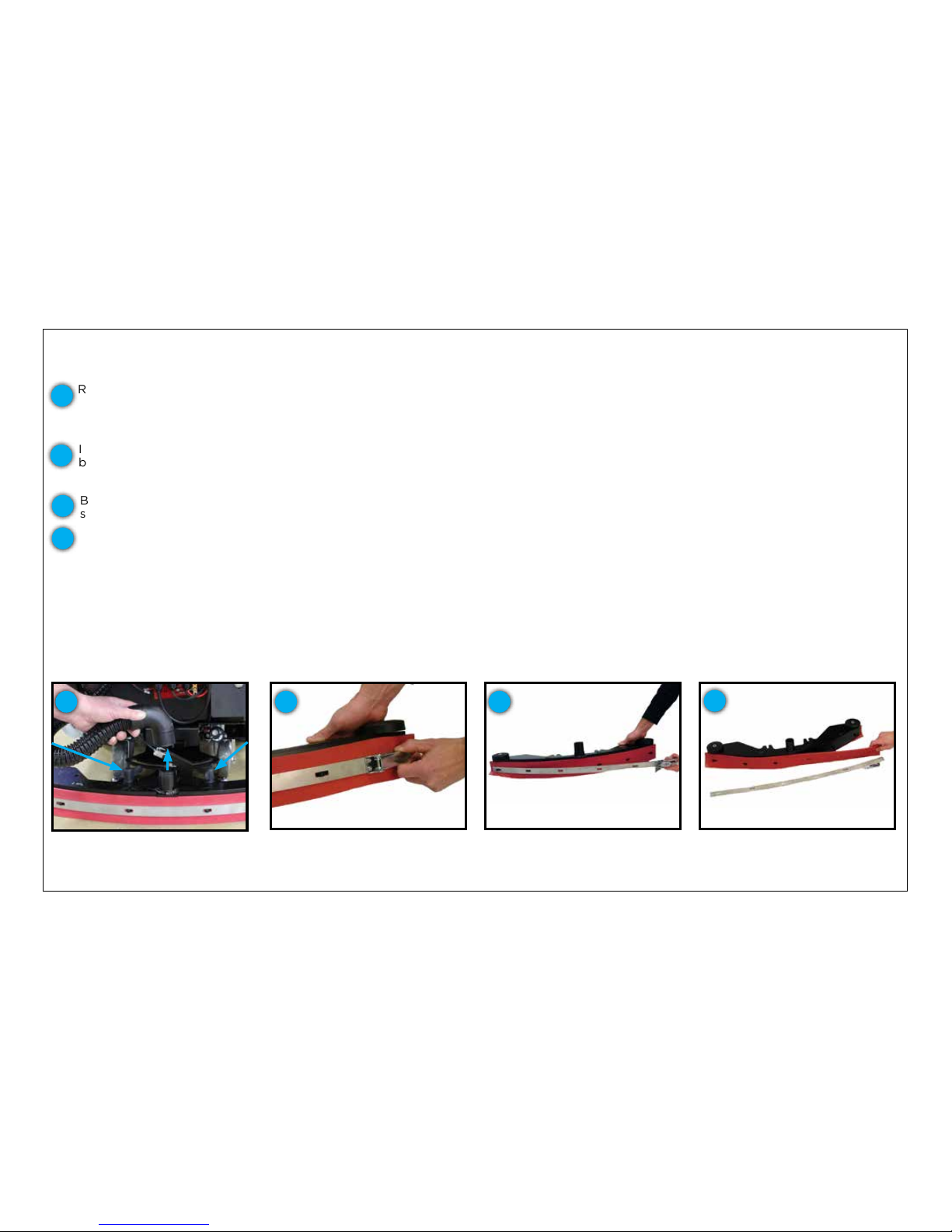
To ip or replace squeegee blades,
release over-center latch
Remove the blade and either ip to
fresh edge or replace
Slide the squeegee retainer off the
hook on the other side
Remove the squeegee assembly from the machine by loosening the easy-grip knobs and detaching the recovery hose at the back of the
machine. Take the squeegee to a drain or utility sink and thoroughly rinse the underside of the squeegee frame and squeegee blades.
Make sure that all particles and debris have been removed. Inspect the neck of the squeegee assembly for debris. If found, clear the
debris and rinse it out.
Inspect the front and rear squeegee blades. If the blade edges are not clearly dened or worn halfway through the thickness of the
blade, then it is time for replacement or to be ipped to another edge. The S-Series mid-size scrubber’s squeegee blades have four
usable edges.
Blade exchange is completely tool-free for fast, easy maintenance. To remove the rear blade, release the over-center latch and slide the
squeegee retainer off the hook on the other side.
To re-attach the blade, align the blade holes with the squeegee frame guides from one end to the other. Slide the retainer over the hook and
press the retainer latch into position on the far end following the guides. Engage the latch to nish the operation.
The front-blade exchange is completed in a similar fashion to the rear blade by removing the front blade retainer, attaching a new blade using
the guides and re-engaging the squeegee retainer.
When squeegee assembly and blade maintenance is complete, re-attach the squeegee assembly by aligning the assembly, tightening the
easy grip knobs and re-attaching the hose.
1
2
3
4
The blade can be removed for replacement or ipped length wise or top to bottom to utilize another blade edge.
2 3
Loosen the two easy-grip knobs and
detach recovery hose to lift away
the squeegee assembly
4
1
Page 27
27
MAINTENANCE
END OF SHIFT
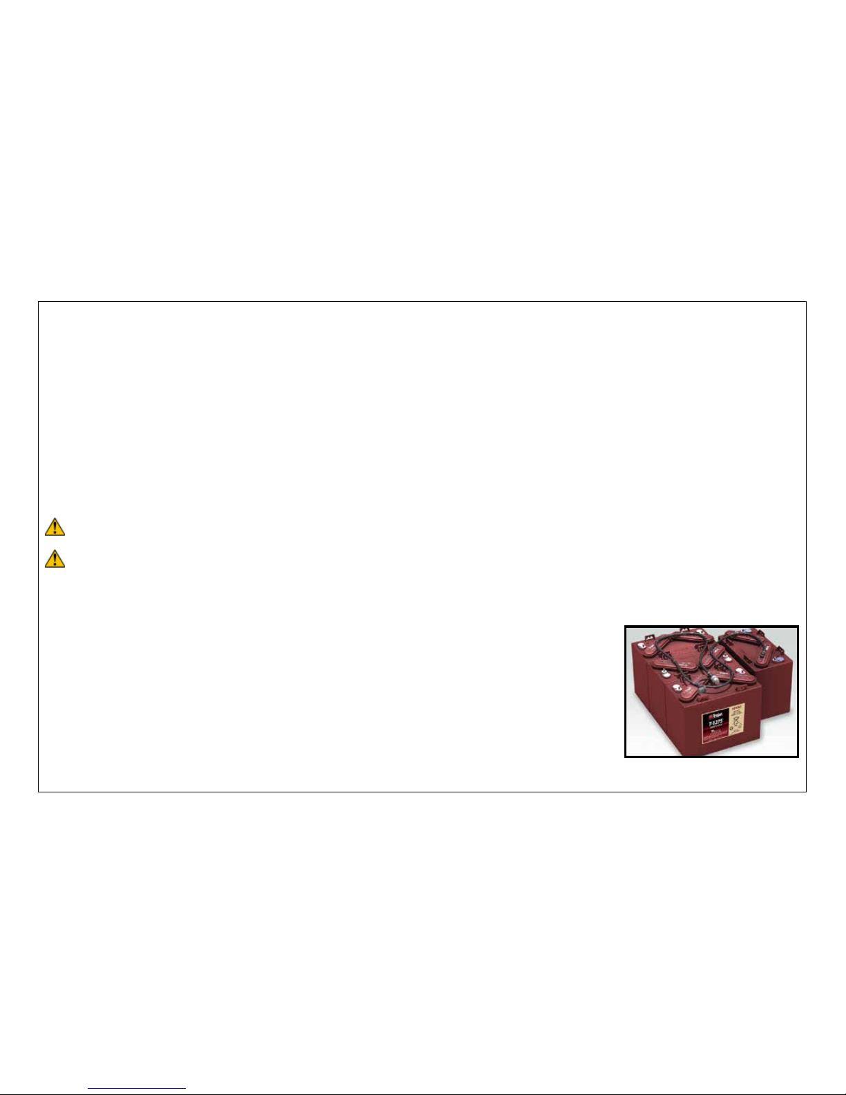
BATTERY MAINTENANCE
Based on research and experience, batteries are the number one nuisance issue and drive a high cost of ownership if not properly maintained.
With the S-Series mid-size scrubber, you can select from two types of batteries: wet, lead acid or sealed, maintenance-free AGM.
WET, LEAD ACID BATTERY MAINTENANCE
Wet batteries, by denition, need water to store energy and protect the internal lead plates. According to the supplier, here are
important things to remember for a proper battery watering process:
1. Do not let the plates get exposed to air. This will corrode the plates
2. Do not ll the water level to the cap. This causes the battery to overow acid, consequently losing capacity and causing a corrosive mess
3. Use distilled or deionized water only
STEP BY STEP BATTERY WATERING PROCEDURE
Battery watering frequency depends upon usage, but the best practice would be to check weekly. Batteries should be fully charged prior to
watering. Refer to the Charging segment of this manual for charging instructions. Once charging is completed, open the vent caps and look
inside the ll wells. Add distilled water until the electrolyte level is approximately 1/8 in (3.2 mm) below the bottom of the ll well. Clean and
replace the vent caps.
HYDROLINK® BATTERY WATERING SYSTEM
HydroLink® is a series of specialized battery caps, tubes and a hand pump that formulates a single-point
battery watering. There is no need to check or ll individual battery cells with this accessory.
HydroLink® comes with an independent, non-mechanical water level indicator that is simple to read. A
white indicator means that the battery needs water and a black indicator means that the battery has
enough water.
After the batteries are charged and the operator has identied that the batteries are low with the indicator,
place the feed hose into a reservoir of distilled water and compress the hand-pump until it becomes hard to
squeeze. This indicates that all the battery cells are lled to the proper level.
HydroLink® battery watering system
WARNING:
Fire or explosion hazard. Batteries emit Hydrogen gas. Keep sparks and open ame away. Keep battery compartment
open when charging.
For safety, when cleaning batteries, wear protective gloves and eye protection. Avoid contact with battery acid.
CAUTION:
Page 28
28
MAINTENANCE
END OF SHIFT
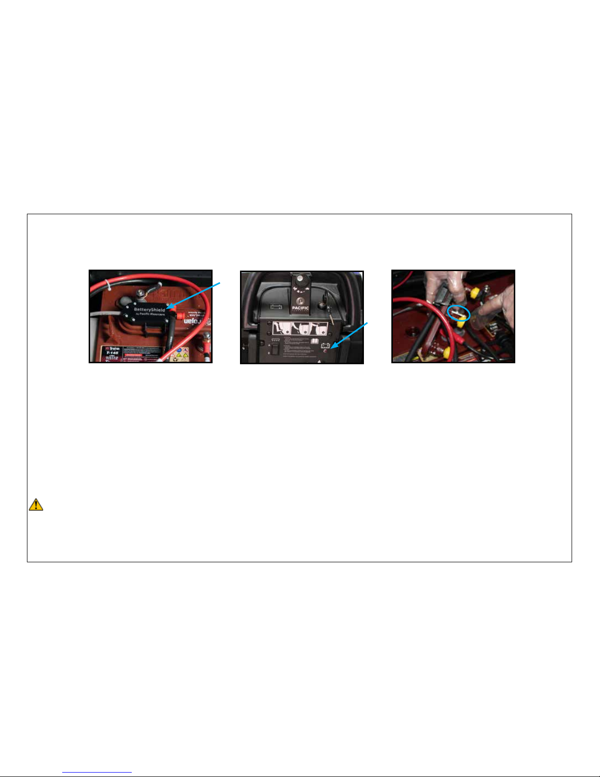
BATTERYSHIELDTM AUTOMATIC WET BATTERY PROTECTION SYSTEM
If your scrubber is equipped with BatteryShield technology, your scrubber will provide you “real time” notication when your wet batteries
need to be watered.
After your machine is charged and you turn the key switch on, BatteryShield will check your water levels for you. You can locate the
BatteryShield optical sensor on the HydroLink® cap on your battery pack and the LED on the back panel of your scrubber.
BatteryShield LED on back panel
BatteryShield optical sensor on
Trojan battery
When your LED remains unlit, it means that your batteries have an acceptable water level. If BatteryShield senses that your batteries need
to be watered, the LED will indicate this with a solid, red light and BatteryShield will not allow your brush motor to function, therefore
preventing further use of the scrubber until the batteries are lled with distilled water using the HydroLink single-point battery watering
system. After lling your batteries, cycle the key switch off then on and your BatteryShield system will be reset.
BatteryShield has been programmed to check the water levels of your batteries after a full charge, so your unit will most likely be in your
janitor’s closet or storage area but if by chance it detects low water during the cleaning operation, it will only shut down the brush
motor preventing the operator from doing any further cleaning. The vacuum motor and transaxle drive motor will still be operable so that
any remaining solution can be recovered and the unit can be transported back to an area where the batteries can be watered.
If your LED has a blinking, red light it means that a HydroLink light pipe needs to be cleaned. Note: Failure to clean your light pipe will limit
BatteryShields’ ability to read the low water condition and may reduce the life of your batteries.
For safety, when cleaning batteries, wear protective gloves and eye protection. Avoid contact with battery acid.
CAUTION:
HydroLink battery cap light pipe
circled above
Remove the HydroLink battery cap that has the BatteryShield optical sensor attached to it. Do not remove the BatteryShield sensor from
the HydroLink cap. Use a clean, damp cloth to wipe the pointed tip and shaft of the light pipe. Snap the HydroLink cap back into place on
the battery. Cycle the key switch. The BatteryShield LED should stop blinking if light tube has been cleaned effectively. If repeated attempts
to clean the light pipe are unsuccessful, a new HydroLink cap will be required.
Page 29
29
MAINTENANCE
END OF SHIFT
PAD DRIVER AND BRUSH MAINTENANCE
This portion of maintenance is simple and quick, but key to keeping your S-Series mid-size scrubber performing at peak levels. Remove the
pad drivers or brushes to check for wear.
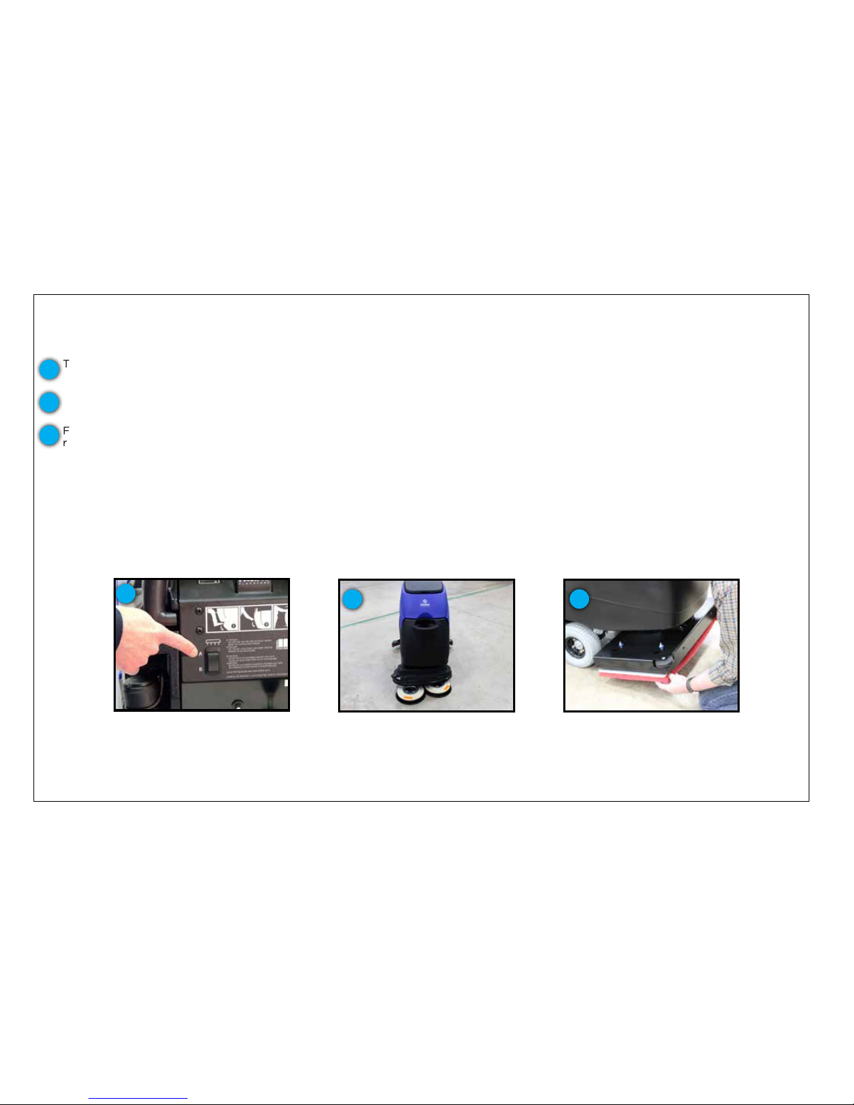
Depress position “A” for 1 second
then depress position “B”
To remove the pad drivers or brushes from your disk unit, locate the automatic off switch on the lower control panel at the rear of the
machine. Depress position “A” for 1 second and then depress position “B”.
For the orbital unit, simply pull off the pad taking care to follow proper safety precautions as indicated on your chemical product label in
regards to coming in contact with solution.
Should the pad or brush show ample wear and have reached their replacement point, simply discard the pad or brush and replace it at the
beginning of your next shift. Brushes should be replaced when the bristle length reaches 3/4 in (19 mm).
Alternatively, if not worn out, you can extend the life of your pad driver, pad or brush by rinsing out any captured debris or sediment and then
hanging it to dry between shifts - a simple step that can lower your cost to clean.
1
2
3
This will “click-off” the pad drivers or brushes.
1
Cleaning tools released by auto on/
off feature
2
Starting at the front corners of the
pad, pull it down & off the
pad driver
3
Page 30
30
PERIODIC MAINTENANCE
CHANGING BATTERIES
To change the batteries in your S-Series mid-size scrubber, move the machine to an area with a level surface, turn off the power switch and
remove the key. If using an off-board charger, make sure that it is located near your machine and that your location is close to an electrical
outlet for charging after installation.
WARNING:
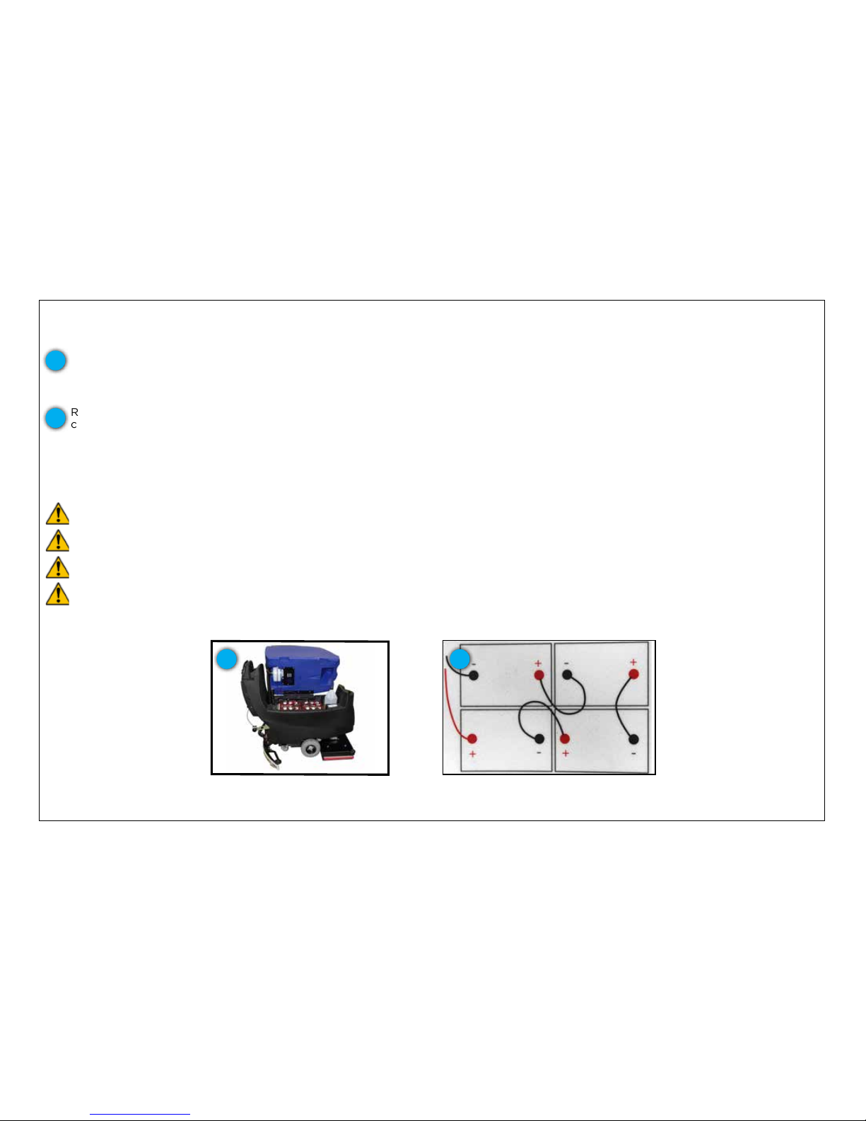
To access the battery compartment, tilt the recovery tank to the fully open position. Using proper open-ended wrench, disconnect the
main ground cable rst and secure terminal away from the batteries. Disconnect main positive cable and secure terminal away from
the batteries. Loosen all terminals on the jumper cables and remove. Attach a suitable battery lifting device and lift the batteries from
the machine.
Reverse the order of the instructions above to install new batteries by orienting and connecting the batteries as shown in the Battery
connection diagram. After installation is complete, be sure to charge your batteries before operating the machine.
NOTE: If changing battery types from wet, lead acid to AGM or vice versa, see Machine Preparation section for instructions on setting
the dip switches on your machines battery charger before beginning the charge cycle to avoid damaging or undercharging your
batteries.
Batteries are a potential environmental hazard. Consult a battery supplier for safe disposal methods.
1
2
Fully open position allowing access
to battery compartment
1
WARNING:
Wear protective gloves and eye protection when handling batteries or battery cables. Avoid contact with battery acid.
WARNING:
Disconnect battery connections before working on the machine.
WARNING:
Short-circuiting or accidentally connecting battery posts or other metallic parts of the machine with a metal or
conductive tool can cause serious personal injury. Use proper tools and take precautions to not accidentally short circuit
battery terminals.
Battery connection diagram
2
Page 31
31
PERIODIC MAINTENANCE
CHECKING THE ISOLATORS ON YOUR S-28 ORBITAL UNIT
Your S-28 orbital scrubber is equipped with an hour meter that is located on the upper control panel.
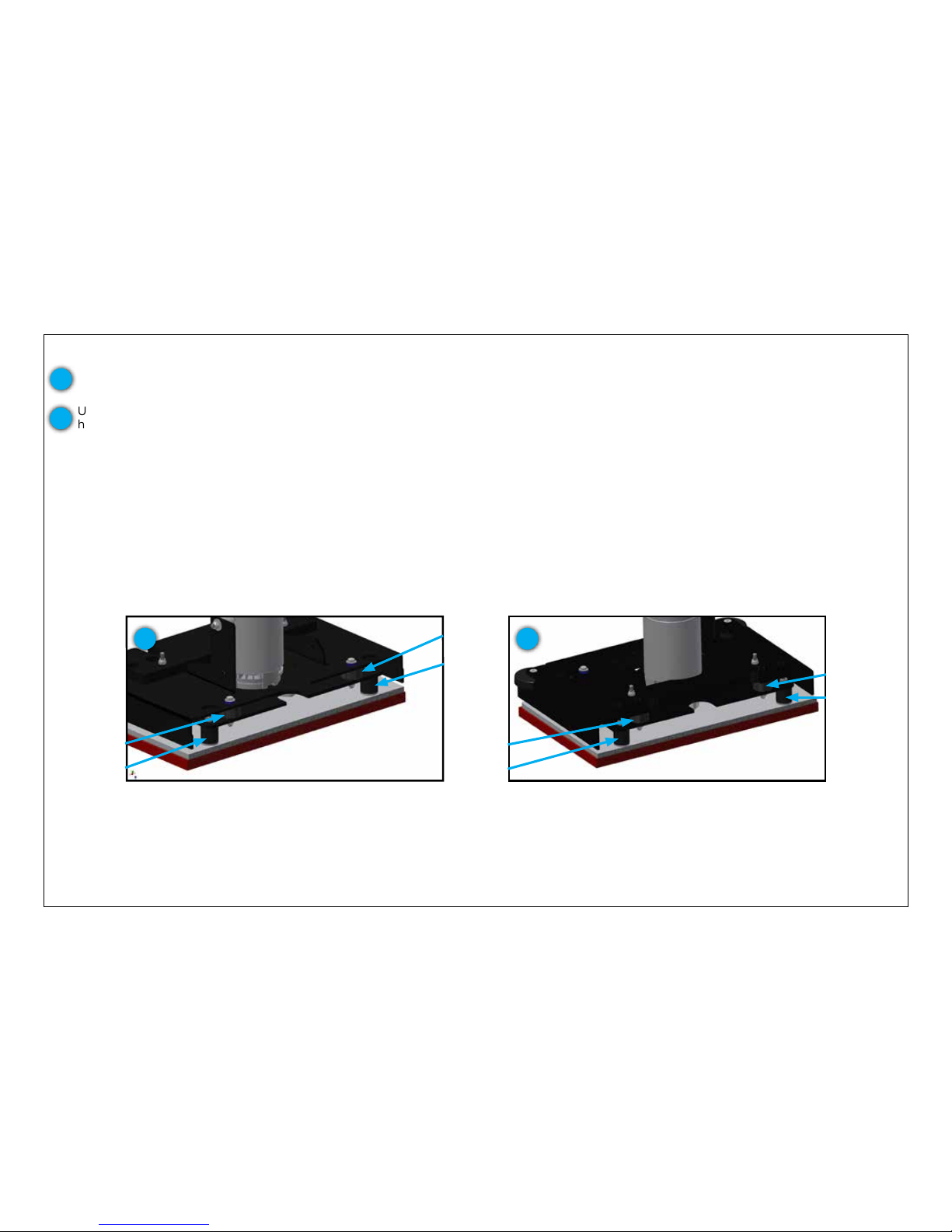
After 300 hours, it is time to check the eight isolators located in the scrub head of the unit.
Using a ashlight, do a visual inspection of the isolators by looking through the openings in the scrub
head and checking for wear or damage to four isolators in the front and four in the rear of the scrub
head. The locations of the isolators are shown below.
1
2
Cross section view of FRONT of orbital scrub head with
isolator locations indicated with arrows
2
Cross section view of REAR of orbital scrub head with
isolator locations indicated with arrows
2
If any of your isolators show signs of wear, degradation or damage, contact an authorized service
center or Pacic Floorcare technical service to nd a local authorized service center to replace all eight
isolators.
After satisfactory inspection or replacement, press and hold the gray button on the hour meter to reset to
another 300 hour period.
Page 32
32
PERIODIC MAINTENANCE
INSPECTING THE HEPA FILTER
Your S-Series mid-size scrubber is equipped with a HEPA lter.
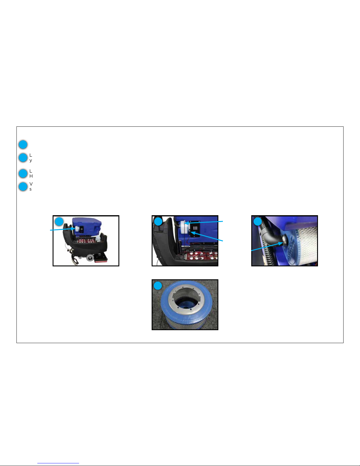
You can locate the HEPA lter by lifting the recovery water tank, opening it as far as it will go using the side handle.
1
Recovery tank shown in fully
open position
1
HEPA lter
Vacuum hose clamp
3
Loosen one of the recovery tank support cable bolts using a 7/16-inch socket head driver so that the tank will swing fully open to give
you access to the HEPA lter.
2
Loosen the vacuum hose clamp located at the top of the HEPA lter with a 5/16-inch socket head driver and pull the cuff off of the
HEPA lter.
3
Inspect the HEPA Filter
Visually inspect the inside of the lter every 200 hours of machine operation. Heavy build up on the lter, which can cause loss of
squeegee performance, indicates the need to replace the lter. Also inspect the outside of the lter for physical damage or holes.
4
4
When reattaching the lter, ensure the large diameter is fully engaged with the seal plate.
Disconnect at either point to
loosen cable
2
Recovery
tank support
cable
Seal plate
Page 33
33
TRANSPORTING YOUR UNIT
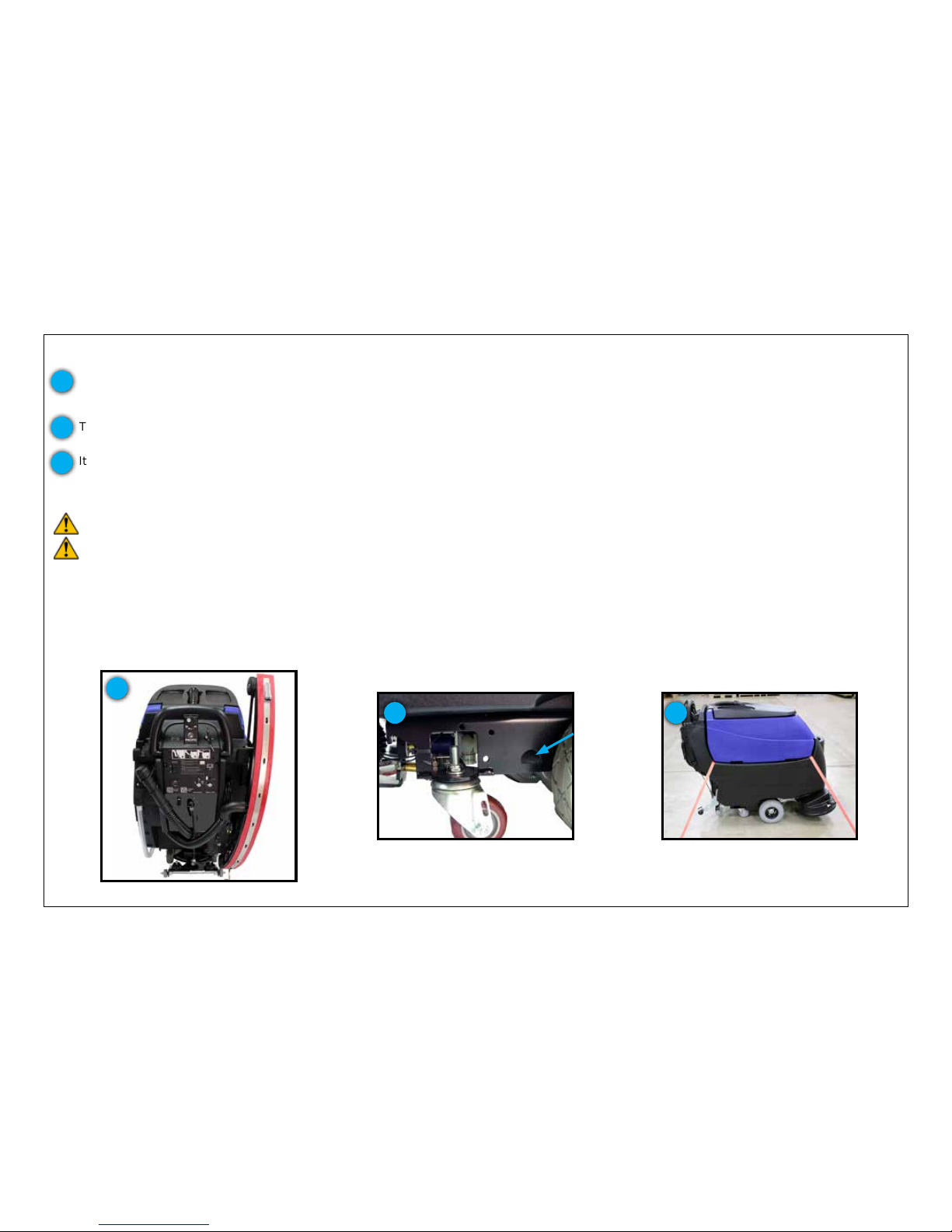
Your S-Series mid-size scrubber was designed so that it could easily be transported on a route cleaning program.
The machine has a tie down holes on each side of the main frame.
It can also be strapped down to a trailer or truck bed using tie down straps inserted between the recovery tank and solution tank
2
3
Tie down locations between
recovery tank and solution tank
3
Tie down location on main frame
2
NOTE: When transporting the machine, turn the machine off.
CAUTION: When transporting the machine, do not lift the machine when batteries are installed.
CAUTION: When transporting the machine, get assistance when lifting the machine.
NOTE: Use a recommended ramp with a maximum of a 12° incline when loading or unloading into/off truck or trailer.
NOTE: When trasporting the machine, use tie down straps to secure the machine to the truck or trailer
NOTE: When transporting the machine, put the scrub head in the lowered position. Make sure the unit is off before doing so.
NOTE: Do not allow the orbital head to rest on a hard surface without a pad attached. This will cause damage to the Mighty-Lok® face.
1
Squeegee assembly in transport
position
1
Easily transport machines in, out or through facilities with the S-Series mid-size scrubber’s unique squeegee hanger feature. Simply
remove the squeegee assembly (see Page 14) while leaving the recovery hose attached, lift the squeegee to a vertical position on the
right side of the machine and place the squeegee tab into the squeegee hanger.
Page 34
34
TROUBLESHOOTING
OPERATOR TOP FIVE TROUBLESHOOTING LIST
Because cleaning equipment can encounter a wide array of environments and debris, various issues can arise that can be quickly xed with
some easy troubleshooting by the operator. Because there are so many scenarios, we’ve generated the top ve troubleshooting list that
addresses the most common issues.
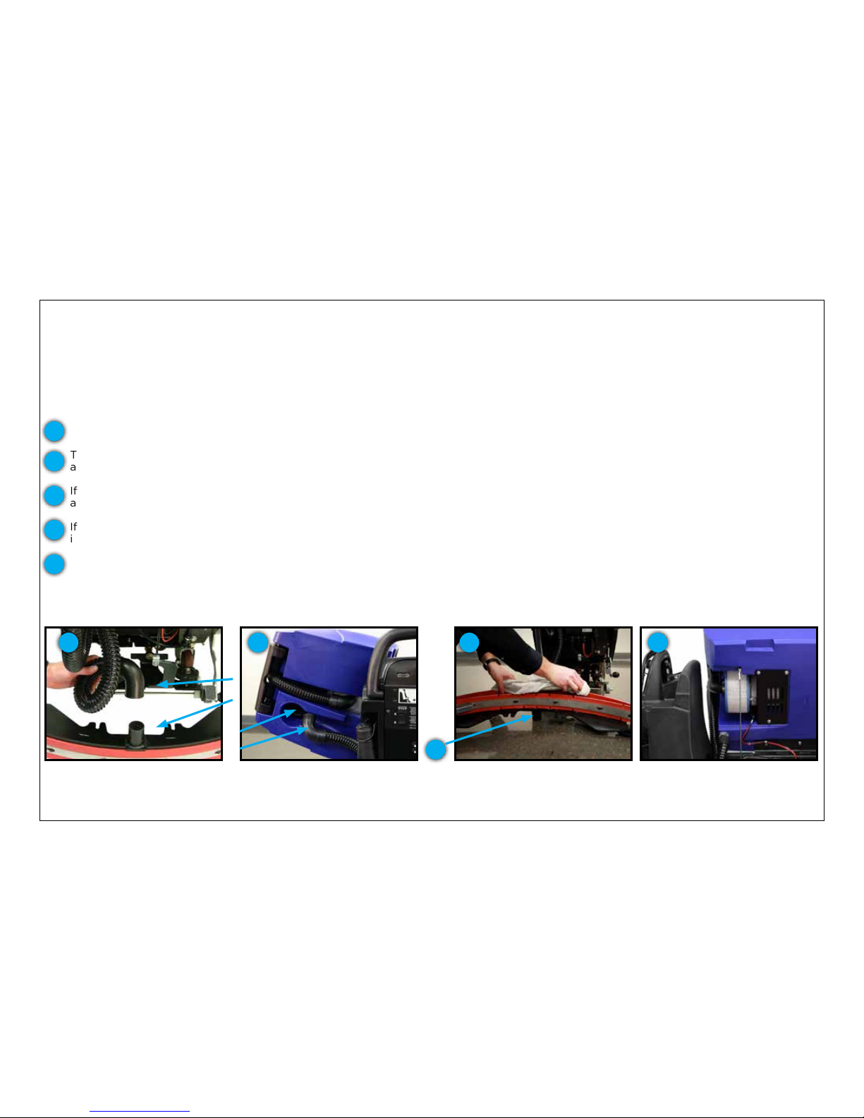
1. MACHINE ISN’T PICKING UP WATER OR IS LEAVING A FILM ON THE FLOOR
If your machine isn’t picking-up water, there are a few key areas of the machine to check. If the vacuum seems to have a higher pitch than
normal, the ball oat in the recovery tank has tripped because the recovery tank is full and needs to be drained. Once drained, check that
the water recovery is working. If it is, then you’ve identied and corrected the issue.
Lower elbow of recovery hose and
squeegee assembly neck
1
1
If still not picking-up water, then it is likely you have a clog in the recovery hose. Start by checking the recovery hose at the lower
elbow connected to the squeegee assembly.
Then, check the upper elbow and the recovery tank orice. If debris is found, clear the clog with your hands or a tool. Should you have
a hose available, rinse the recovery hose and tank orice to ensure all the debris is removed.
If a clog isn’t identied in the recovery hose, check the squeegee neck by loosening the easy grip knobs, removing the squeegee
assembly and ipping it over. Clear the debris, and again, if a hose is available, rinse the squeegee opening.
If still not recovering properly, check your rear squeegee blade edge for wear or debris. If debris is present, clean the blade. If the edge
is worn to half the blade thickness, ip to a new blade edge or order a replacement blade.
2
Upper elbow of recovery hose and
recovery tank orice
2
After checking for wear, wipe the
blade or ip it to a new edge
3
4
3
4
Finally, should you still have recovery issues, contact your distributor or Pacic Floorcare for technical support.
5
Remove and visually inspect the inside of the HEPA lter. Major discoloration or build up can cause reduced vacuum performance.
Replace HEPA lter if necessary.
Remove the HEPA lter and visually
inspect it. Replace if necessary
5
Page 35
35
TROUBLESHOOTING
OPERATOR TOP FIVE TROUBLESHOOTING LIST
2. MACHINE RUN TIME HAS DECREASED
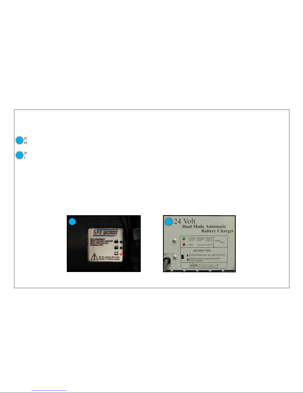
If the machine run time has decreased, there are three potential issues that must be checked: The charger may not be plugged in or
working, the wet, lead acid batteries may need watering or the batteries need to be replaced.
First, check the charger by plugging it in.
Off-board charger LEDs
(charger appearance may vary)
On-board charger LEDs
If an on-board charger, check the three LEDs. If none are on, then you likely have a faulty charger and it will need to be replaced.
However, if the lights are on and the red or yellow light is on, then the batteries aren’t fully charged and the charge cycle needs to be
completed. If the green light is on, then the charger is working and the next step is to consider the batteries.
If an off-board charger, check the charge status LED. If it is not lit or blinking, then you likely have a faulty charger and it will need to be
replaced. However, if the light is on and is blinking then the batteries aren’t fully charged and the charge cycle needs to be completed.
Also, check for the fault LED to be lit and if so, review the manual that comes with your off-board charger for fault details.
If the batteries are wet, lead acid batteries, check the water levels in the battery cells. If they require watering, refer to the Battery
Watering segment of this manual.
If the batteries don’t require watering and are over 18 months old, you’ve likely started to reach a point in the battery’s life where their
capacity is starting to decline. If you are able to meet your run time requirements, then you still have some useful life left. However, if
the capacity has reduced the run time to below your requirements, then it is time to replace the batteries. See Changing Batteries
segment of this manual for further instructions on how to replace your batteries.
If none of these factors are present and you are still not getting expected run times, contact your distributor or Pacic Floorcare for
technical support.
1
2
1 2
Page 36
36
TROUBLESHOOTING
OPERATOR TOP FIVE TROUBLESHOOTING LIST
3. MACHINE WON’T DISPENSE WATER
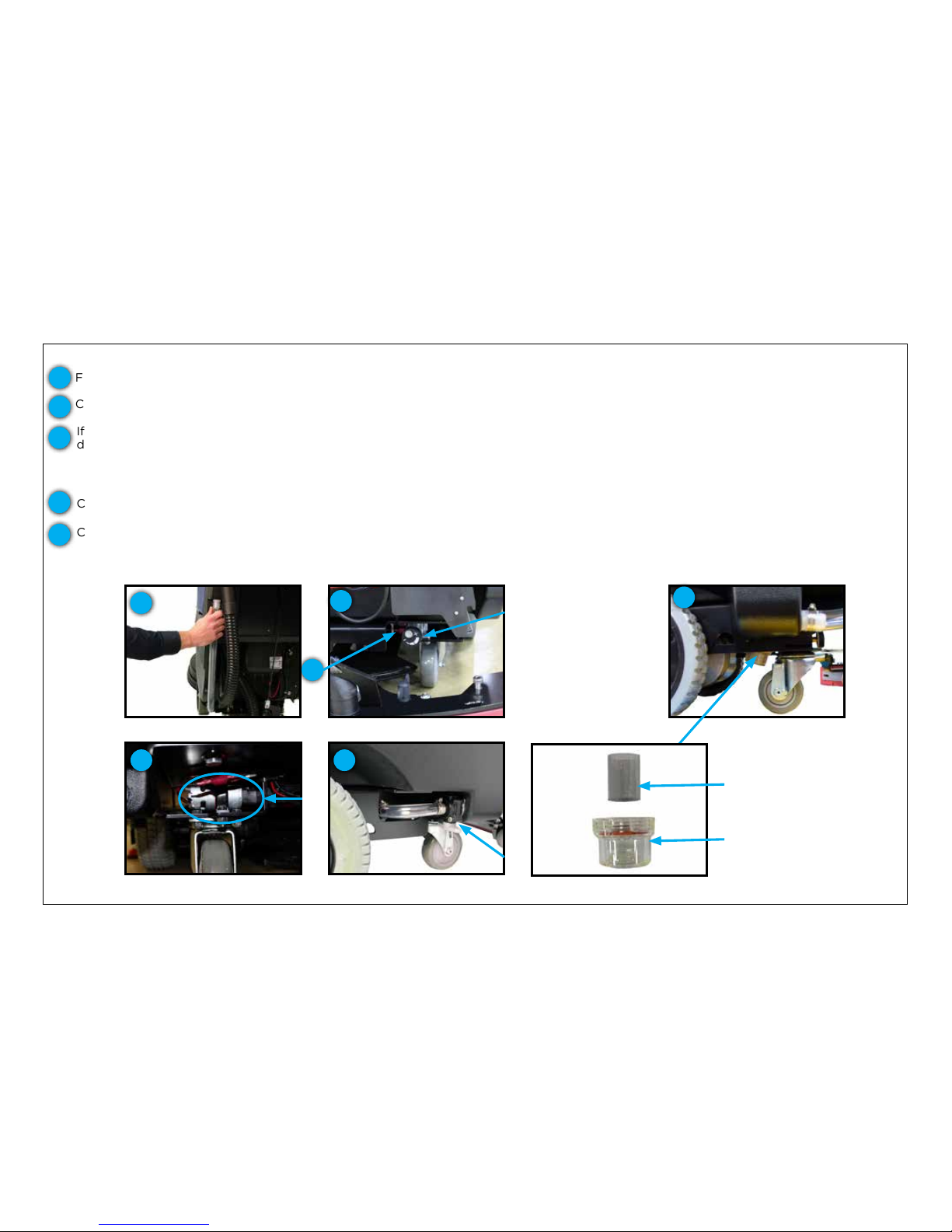
First, when this issue occurs, check the solution tank sight gage for water level. If empty, ll the tank with cleaning solution.
Check the solution ow adjustment knob and ensure that the knob is adjusted to the solution ow level you desire.
1
2
Check sight gage hose for
solution level
1
Sight gage hose
Sight gage hose
Inline lter screen
Inline lter cap
3
If there is solution in the sight gage and the solution ow adjustment knob is properly positioned, then the lter is likely clogged with
debris and needs to be cleaned. Start by draining the solution tank. Unscrew the inline lter, located on the underside of the unit between the wheels and the casters, and clean out the debris. Once clean, re-attach the lter and tighten it until snug. Ensure the screen
lter element is aligned properly with the body of the lter during reassembly. Fill the solution tank and check for solution ow. If
solution is owing, you’ve identied the issue and you can return to cleaning.
3
If none of the actions listed above x the solution ow, contact your distributor or Pacic Floorcare for technical support.
Check the wire connections to the valve.
4
Solution ow adjustment knob
and wire connections
2
4
Check to make sure that the ball valve is open. The handle of the ball valve should be in line with the solution ow direction.
4
Check to make sure that the ball
valve is open
5
Check solution pump (circled)
for vibration from rear of unit
4
Page 37
37
TROUBLESHOOTING
OPERATOR TOP FIVE TROUBLESHOOTING LIST
4. RECOVERY TANK NOT DRAINING
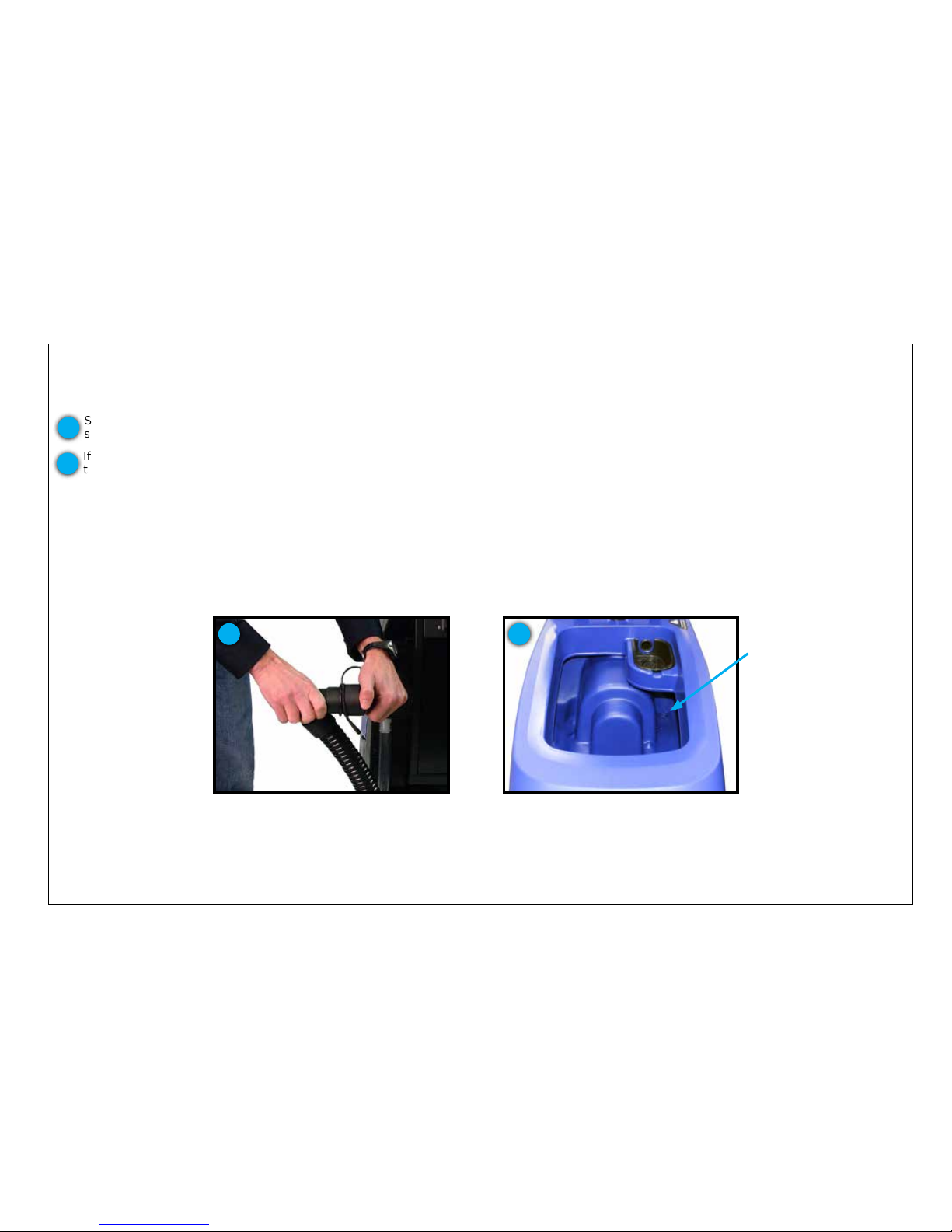
If your recovery tank is not draining, there is a clog somewhere in the draining system. The two main areas of potential clogging are at the
tank drain or at the restriction collar on the drain hose.
Check for clog in the restriction collar
Check for clog in the recovery tank at
the drain opening
Drain opening
1 2
Start by checking the restriction collar being sure to keep the hose well above the top of the recovery tank so that the water doesn’t
splash out once the debris is cleared. If the clog is located here, clear the clog with your hand or a tool and then drain as normal.
If the clog is not located at the restriction collar, then it is likely in the recovery tank at the drain opening. In this case, we suggest that
the operator put rubber gloves on prior to submerging their hand to check for the clog. Once the clog is found, clear the drain and then
empty as normal.
In the unlikely event that the clog is in another part of the drain hose, we encourage utilizing a water hose to back ush the clog from the
recovery hose. Of course, a long thin tool of some kind can be used as well, but be extremely careful not to puncture the hose wall.
If a clog isn’t found in the system, contact your distributor or Pacic Floorcare for technical support.
1
2
Page 38
38
TROUBLESHOOTING
OPERATOR TOP FIVE TROUBLESHOOTING LIST
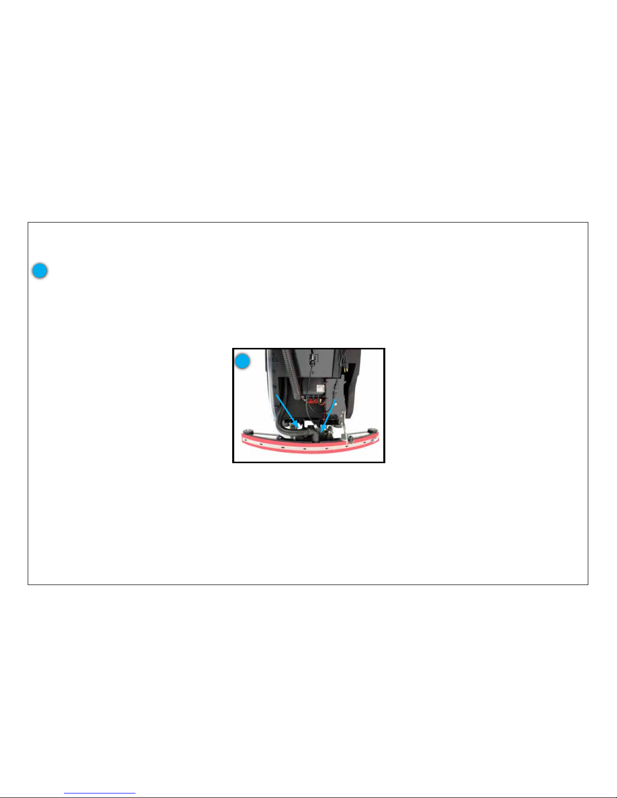
5. SQUEEGEE ISN’T PICKING UP WATER IN TIGHT TURNS
The squeegee is designed to swing fully from left to right to the point where the squeegee system almost touches the casters. Should it be
stopping well short of this, then it is likely that the recovery hose is not routed properly and has become an obstruction.
Properly routed recovery hose
1
To x this, check the routing of the recovery hose to be sure that it is not impeding the squeegee assembly from swinging.
If this isn’t the issue, contact your distributor or Pacic Floorcare for technical support.
1
Page 39

TROUBLESHOOTING GUIDE
ISSUE POTENTIAL CAUSE PROPOSED SOLUTION
Insufcient water to the brushes
Solution ow setting is too low
Make sure the solution control valve is open by
adjusting the solution ow knob
Solution tank is empty
Check the sight gage for solution level. If low or
empty, add water and detergent
Inline solution lter may be clogged
Remove inline lter cap & screen to check for clog.
Rinse and put back in place
Solution dispensing tubes may be
clogged, kinked or damaged
Visually inspect tubes
Solution dispensing pump is not
running in chemical injection system
Make sure pump is running by feeling for slight
vibration. Replace pump if necessary
Ball valve at the outlet of the solution
tank is closed
Open valve. Indicated by the handle in line with the
solution ow direction
Squeegee isn’t drying the oor well
Squeegee blades may be dirty or worn
Remove the squeegee assembly, rinse it off and wipe
the blades down. Inspect edges for damage or wear.
Flip or replace blades as needed
Recovery hose may not be secure at
connections
Make sure upper recovery hose elbow is secure at the
recovery tank orice. Make sure that lower recovery
hose elbow is secure on squeegee assembly neck
Recovery hose or squeegee assembly
may be obstructed
Remove recovery hose and run water through it to
check for any clogs. Remove squeegee assembly and
check for a clog in the neck of the assembly
Recovery hose may be damaged Check for damage. Replace if damage found
Squeegee assembly height may be out
of adjustment
Check the squeegee height. See Machine
Preparation segment of manual for squeegee height
adjustment instructions
Ball oat may be damaged or clogged
and it is obstructing air ow
Check to see that the ball oat is moving freely
and is clean
Recovery tank is full Empty recovery tank
Recovery tank lid is not sealing
Make sure that the lid is in the proper position and
that there isn’t damage to the gasket. Replace gasket
if damage found
Drain hose cap may be loose
Make sure cap is clean and has been pressed in
tightly
Batteries may be discharged
Check battery indicator and if necessary, recharge
batteries
HEPA lter is clogged
Visually inspect the inside of the lter and replace if
necessary
Machine will not turn on
Key switch may be faulty Contact a service center to have tested
Batteries may be discharged
Charge your batteries until charger indicates cycle is
complete
Batteries may be faulty Replace batteries
Battery cable(s) may be loose Check connections and tighten if necessary
Page 40

TROUBLESHOOTING GUIDE
ISSUE POTENTIAL CAUSE PROPOSED SOLUTION
Machine isn’t cleaning satisfactorily Pad or brush may be worn
Inspect & replace if necessary. Brushes should be
replaced when the bristles reach a length of 3/4 in
(19 mm)
Excessive foam is being produced in the recovery tank
Detergent used is not a low foaming
detergent
Check bottle label. Use low foaming detergent or
add a small quantity of defoamer to the recovery
tank. More foam is generated when a oor is lightly
soiled. Use less detergent if this is the case
Detergent dispensing setting is too
high on chemical injection system
Turn the detergent setting to a lower ratio/ow rate
Brush motor will not activate
Scrub head is still in the transport/
storage position
Lower scrub head to operating position
Batteries are discharged to the point
that the brush motor is shut down
Recharge the batteries
Brush motor or wiring may be faulty Contact a service center for testing
Brush motor circuit breaker has been
tripped
Reset brush motor circuit breaker on back panel of
scrubber
Brush motor relay may be faulty Contact a service center for testing
Scrub head switch may be faulty Contact a service center for testing
Handle switch may be faulty Contact a service center for testing
BatteryShield LED is lit indicating the
batteries need water
Use the HydroLink system to ll the batteries with
distilled water
Vacuum motor will not turn on
Squeegee is still in transport/storage
position
Lower squeegee to operating position
Vacuum motor relay may be faulty Contact a service center for testing
Vacuum motor or wiring may be faulty Contact a service center for testing
Vacuum motor will not turn off
Still in delay mode Wait ten (10) seconds
Faulty vac relay Contact a service center for testing
Traction drive does not activate
Traction drive motor circuit breaker
has been tripped
Reset traction drive motor circuit breaker on back
panel of scrubber
Speed control knob is turned too far
to the left
Rotate knob to the right
Traction drive motor or wiring may be
faulty
Contact a service center for testing
Traction drive motor controller may
be faulty
Contact a service center for testing
Run time is short
Batteries are discharged Recharge the batteries for a full cycle
Wet batteries may need to be watered See End of Shift Maintenance segment of manual
Batteries are defective Replace batteries
Battery charger is defective Repair or replace charger
Scrub head is locked in high down
pressure setting
Change scrub head setting from high down pressure
setting to normal operation setting
Charger is set to incorrect battery
type
Verify dip switch setting is correct on charger
using Setting the Dip Switches segment in the
Machine Preparation segment of this manual
Page 41

TROUBLESHOOTING GUIDE
BATTERY POWER LEVEL INDICATOR FAULT CODES
TRANSAXLE DRIVE UNITS
CODE (FLASHING LED
S) POTENTIAL CAUSE PROPOSED SOLUTION
One Low voltage shut-off. Brush motor shut down
Recharge batteries
Check battery connections
Two Battery charge level getting low Recharge batteries
Three
Traction drive motor tripped Remove overload condition and reset
Traction drive motor has short circuited Contact a service center for testing
Four Battery lockout has occurred Recharge batteries right away
Eight Controller tripped Contact a service center for testing
Ten High battery voltage reading Check battery connections
None Indicator is in sleep mode Turn power key off then on to restore
Sequencing lights Activation handle is engaged Release activation bail
41
Page 42

SUB-ASSEMBLY DESCRIPTION PART NUMBER S-24 QTY
S-28 DISK
QTY S-32 QTY
S-28
ORBITAL
QTY
OPTIONS
QTY
Charger, On-board Cord, 9 ft (3 m) 908128* 1 1 1 1
Charger, On-board Charger, on-board, 24VDC 852407 1 1 1 1
BatteryShield
®
Sensor assy, BatteryShield 878518 1
BatteryShield
®
Relay, BatteryShield 911685 1
Chemical Injection Pump, solution 877005 1
Chemical Injection Pump, detergent 877002 1
Chemical Injection Controller, solution 872401 1
Chemical Injection Valve, check, .188x.5 barb 879402 1
Chemical Injection Cap, 38 mm 871501 1
Chemical Injection Filter, inline S764P2 1
Controls Circuit breaker, 35 amp 911681
2 2
Controls Circuit breaker, 30 amp 911622
2 1 1 2
Controls Switch, snap, with roller 911646
1 1 1 1
Controls Switch, key 911647
1 1 1 1
Controls Key, set of two 855012
1 1 1 1
Controls Switch, push, on/off 911649
1 1 1
Controls Pot, speed 911664
1 1 1 1
Controls Switch, push, reverse 911653
1 1 1 1
Controls Cable, lift, clevis 852401
1 1 1 1
Electronics Controller, traction 879101 1 1 1 1
Electronics Contactor, 24VDC, 100 amp 912401 1 2 2 1
Electronics Contactor, 24VDC, 70 amp 912402 2 2 2 1
Frame Wheel, traction, 9 in (229 mm) 879703 2
Frame Wheel, traction, 8.74 in (222 mm) 879705 2 2 2 2
Frame Caster, 4 in (102 mm) 875017* 2 2 2 2
Frame Filter, 80 mesh 843319 1 1 1 1
Frame Valve, solenoid, 24VDC 859401 1 1 1 1
Frame Knob, adjust, .25 bore 855001 1 1 1 1
*Indicates wear item
SUGGESTED SERVICE PART LISTING
Page 43

SUB-ASSEMBLY DESCRIPTION PART NUMBER S-24 QTY
S-28 DISK
QTY S-32 QTY
S-28
ORBITAL
QTY
OPTIONS
QTY
Head Belt, v-groove 903046*
1
Head Bearing, .75-inch, sealed 902053
4
Head Guide, driver 853803*
1 1 1
Head Guide, pad 853804*
2 2
Head Guide, pad, plastic 873801*
2
Head Wheel, guide 859703
1 1
Head Mount, isolator 855604
4
Head Motor, 2200 rpm 855204
1 1
Head Motor, gear, brush 875201
2 2
Head Bearing, .50 inch, sealed 902035
6
Head Hub, driver, brush 854302 2 2
Head Center lock, replacement 875113* 2 2 2
Head Plate, clutch, with screws 876614 2 2 2
Recovery Filter, HEPA 873304* 1 1 1 1
Recovery Hose, drain, capped 854101* 1 1 1 1
Recovery Gasket, cover, press-in 873401 1 1 1 1
Recovery Float, ball 223370 1 1 1 1
Recovery Hose, vacuum 854103 1 1 1 1
Recovery Motor, vacuum, 24VDC, 3 stg 875202 1 1 1 1
Recovery Foam, noise, vacuum, short 853309 1 1 1 1
Recovery Gasket, foam, vacuum 873314 1 1 1 1
Recovery Hose, squeegee, 90° cuff 874101* 1 1 1 1
Recovery Puck, Bromine, 4pk 877007* 1 1 1 1
Recovery Tray, debris 879201* 1 1 1 1
Recovery Tray, puck 879202 1 1 1 1
Solution Switch, snap, bent lever 911682 1 1 1 1
Squeegee Linkage Strap, static 878504* 1 1 1 1
Squeegee Linkage Bearing, rod end, .50 fem 902051 1 1 1 1
*Indicates wear item
SUGGESTED SERVICE PART LISTING
Page 44

SUB-ASSEMBLY DESCRIPTION PART NUMBER S-24 QTY
S-28 DISK
QTY S-32 QTY
S-28
ORBITAL
QTY
OPTIONS
QTY
Squeegee Blade, rear, 35 in (889 mm) Linatex 870701* 1
Squeegee Blade, rear, 35 in (889 mm) urethane 870707* --> 1
Squeegee Blade, front, 35 in (889 mm) Linatex 870702* 1
Squeegee Blade, front, 35 in (889 mm) urethane 870708* -> 1
Squeegee Blade, rear, 40 in (1,016 mm) Linatex 870703* 1 1
Squeegee Blade, rear, 40 in (1,016 mm) urethane 870709* --> --> 1
Squeegee Blade, front, 40 in (1,016 mm) Linatex 870704* 1 1
Squeegee Blade, front, 40 in (1,016 mm) urethane 870710* -> -> 1
Squeegee Blade, rear, 44.5 in (1,130 mm) Linatex 870705* 1
Squeegee Blade, rear, 44.5 in (1,130 mm) urethane 870711* --> 1
Squeegee Blade, front, 44.5 in (1,130 mm) Linatex 870706* 1
Squeegee Blade, front, 44.5 in (1,130 mm) urethane 870712* -> 1
Squeegee Clamp, over-center, band 852002 2 2 2 2
Squeegee Wheel, guide 859703 2 2 2 2
*Indicates wear item
SUGGESTED SERVICE PART LISTING
44
Page 45
45
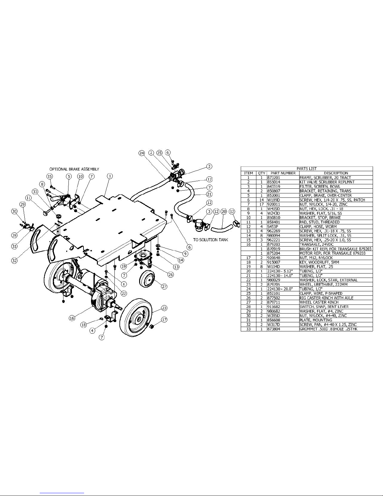
FRAME ASSEMBLY WITH URETHANE WHEELS
Page 46
46
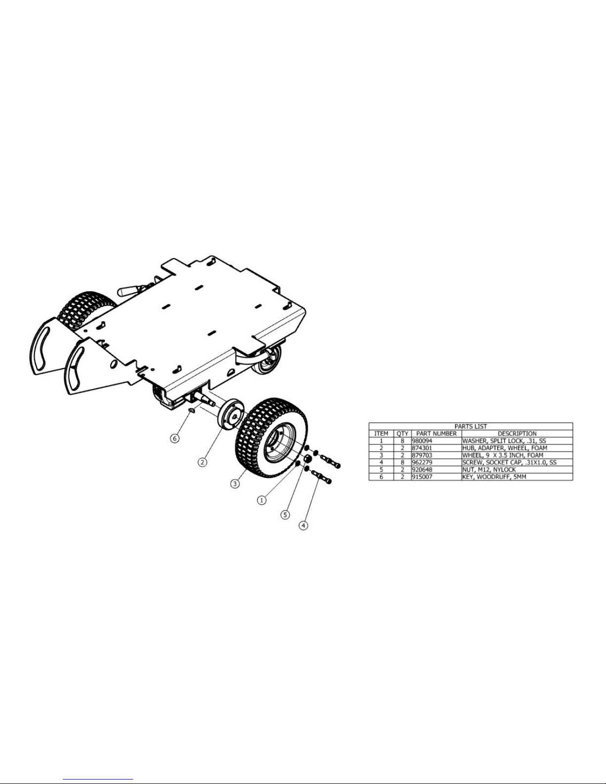
FRAME ASSEMBLY WITH FOAM-FILLED WHEELS
Page 47
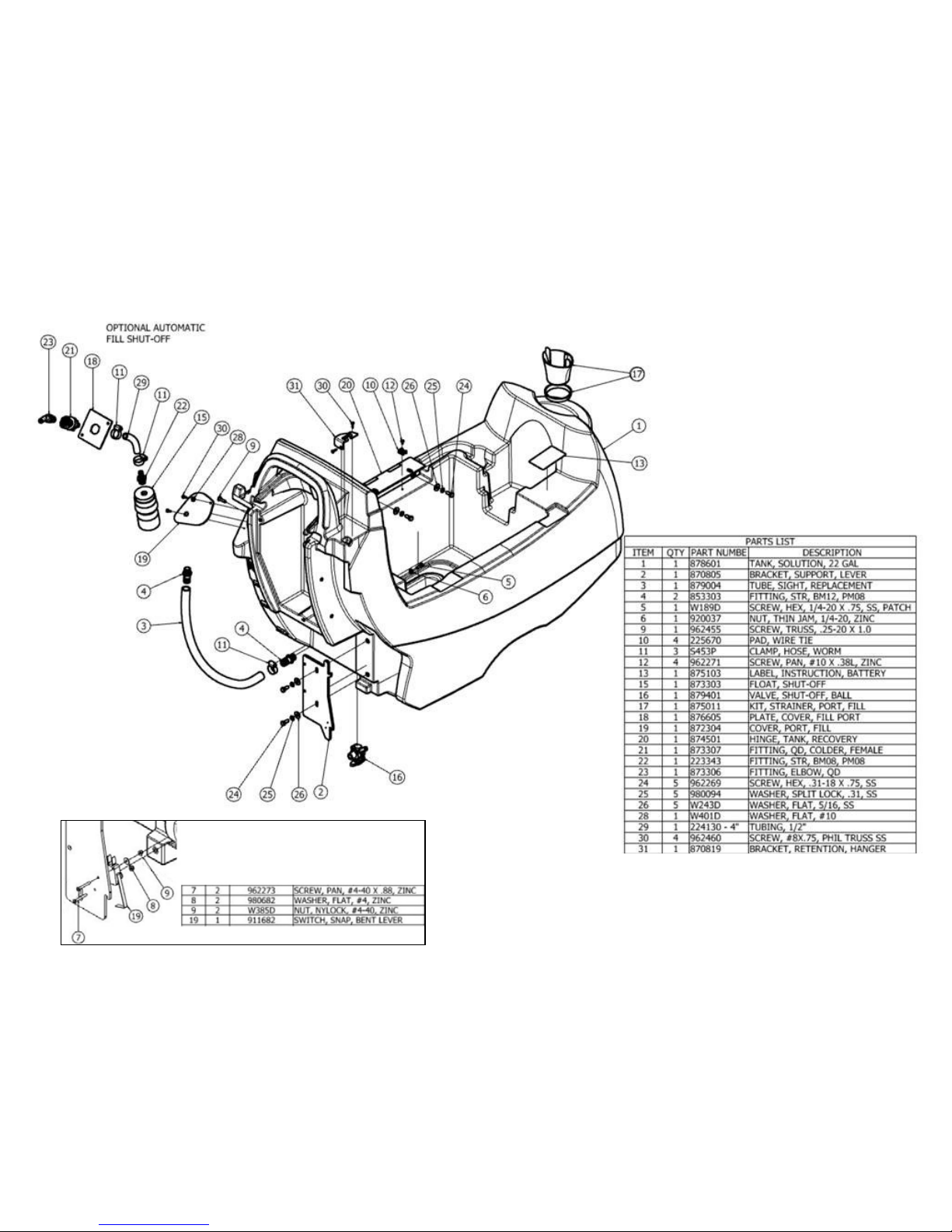
47
SOLUTION TANK ASSEMBLY
Head switch location for all machines
built prior to March 13, 2015 and
before serial #102090
Page 48
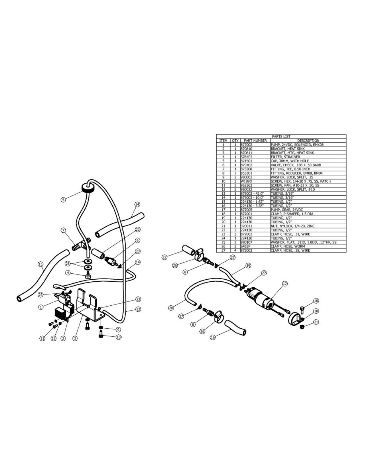
48
ON-BOARD CHEMICAL INJECTION ASSEMBLY (OPTIONAL)
Page 49
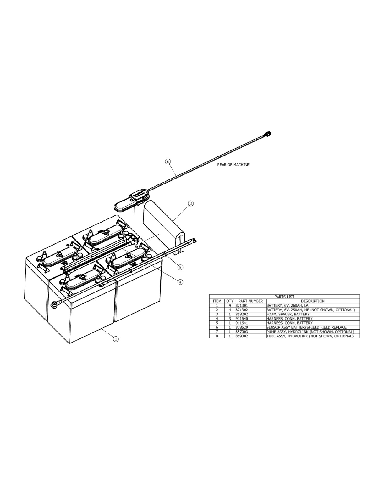
49
BATTERY ASSEMBLY
Page 50
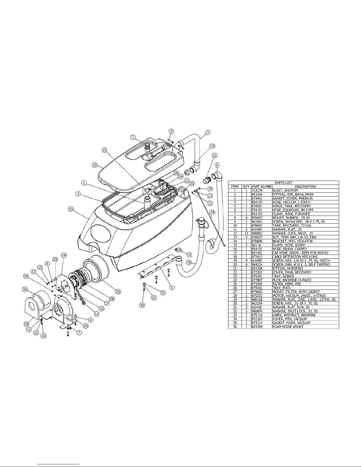
50
RECOVERY TANK ASSEMBLY
Page 51
51
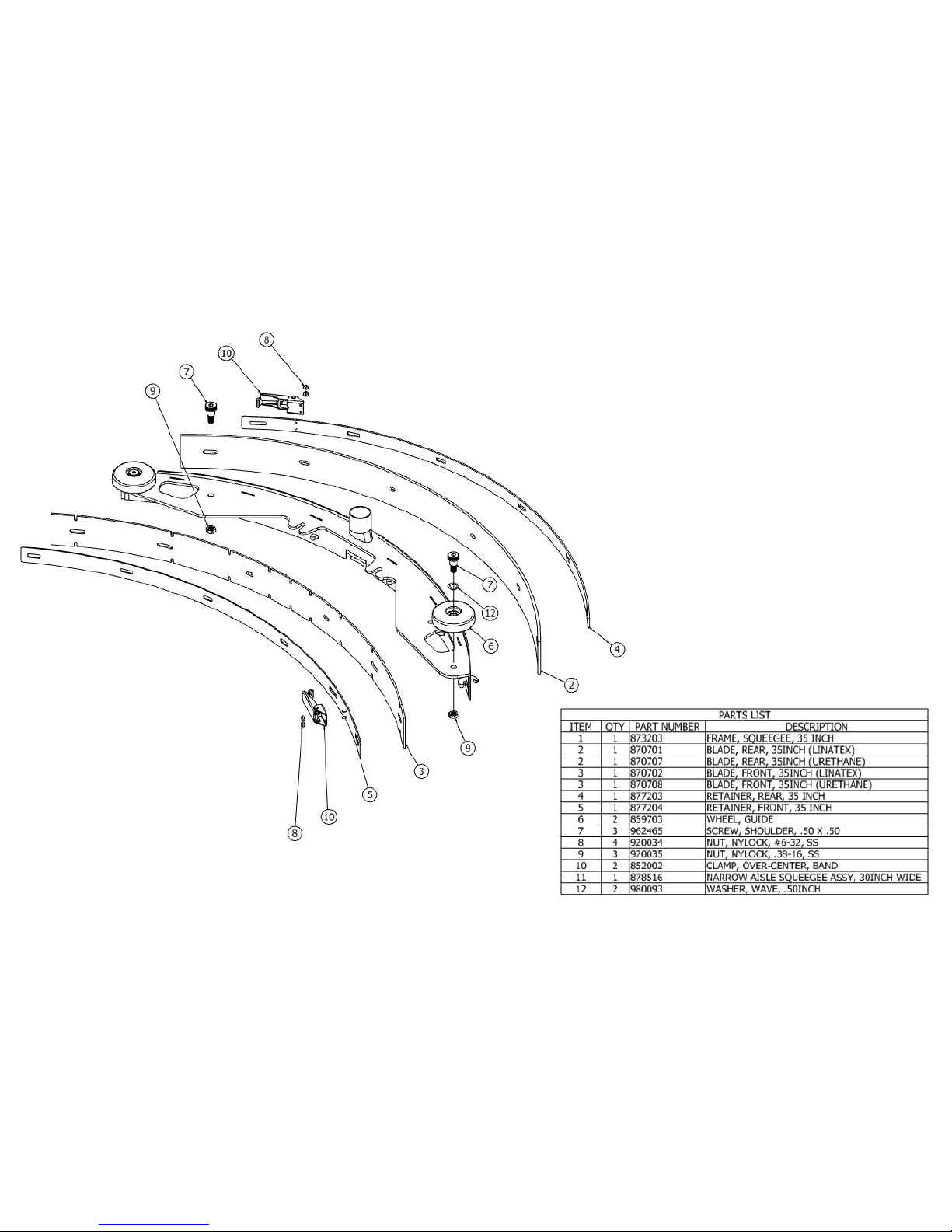
SQUEEGEE ASSEMBLY, S-24
Page 52
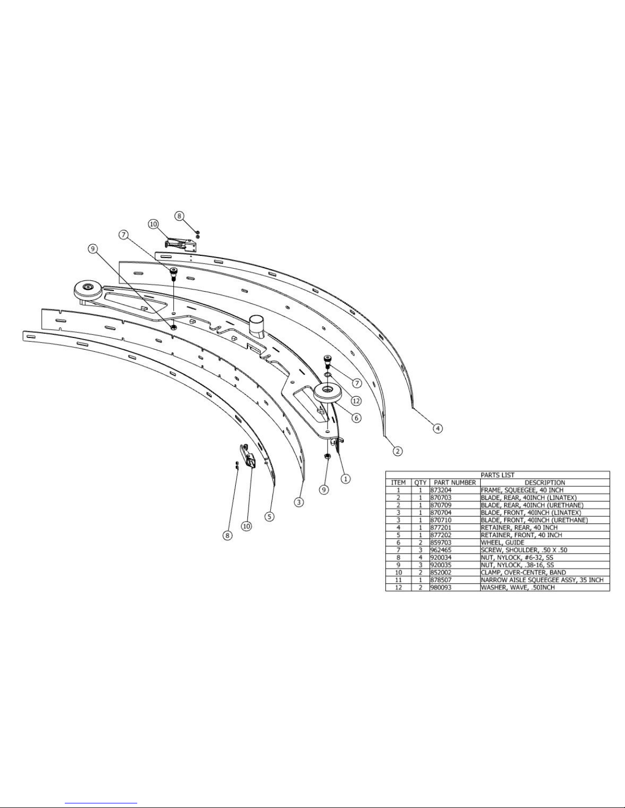
SQUEEGEE ASSEMBLY, S-28
52
Page 53
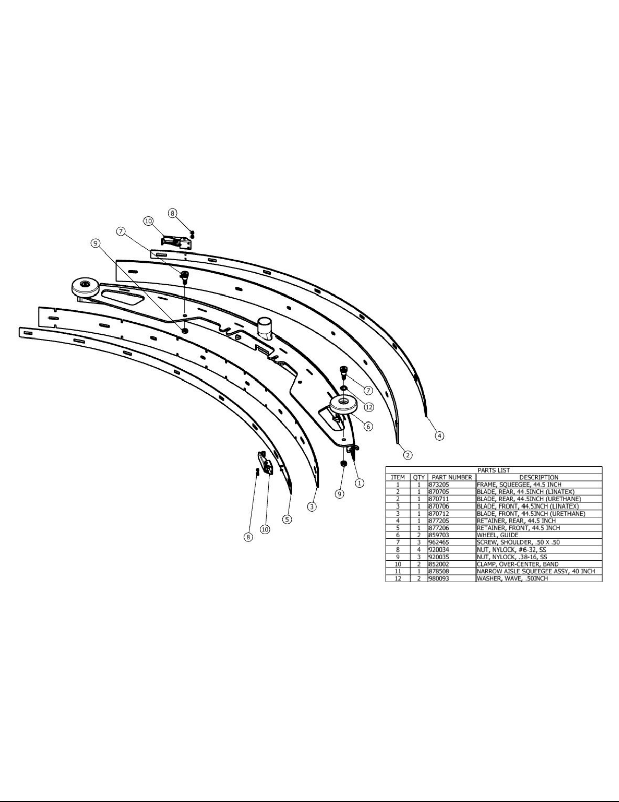
SQUEEGEE ASSEMBLY, S-32
53
Page 54
54
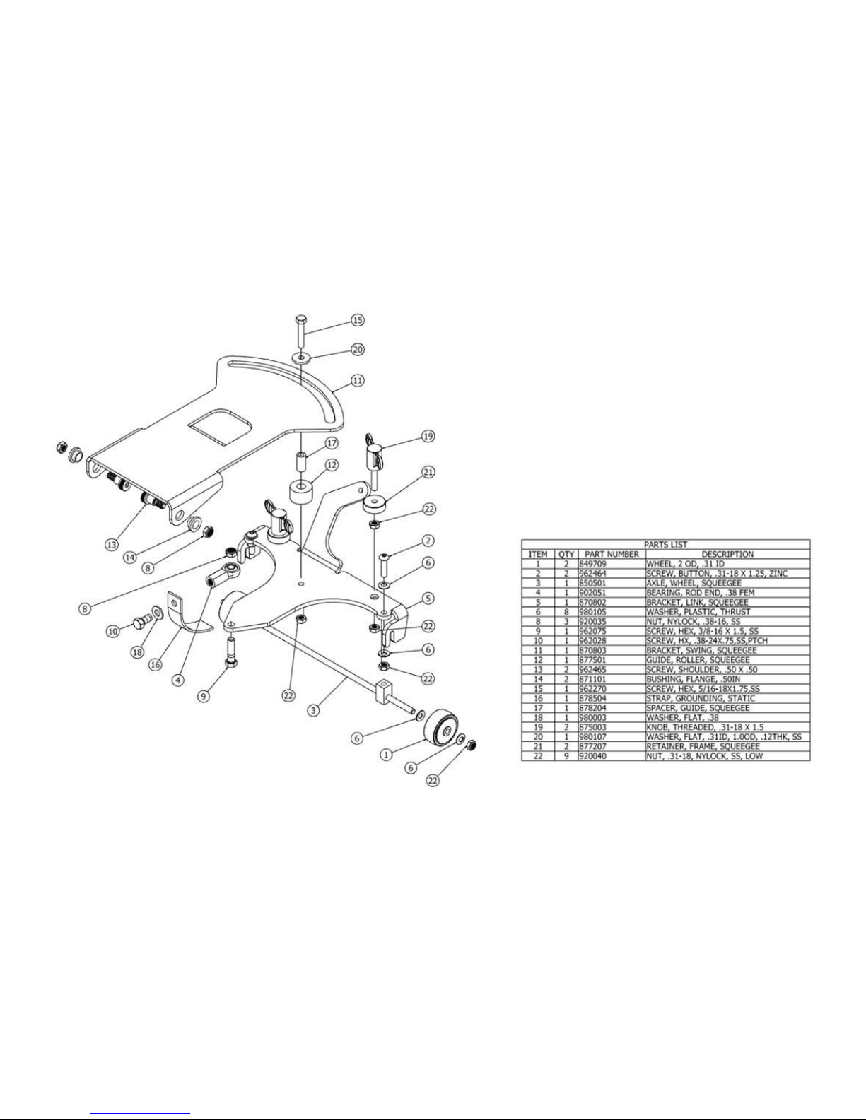
SQUEEGEE LINKAGE ASSEMBLY
Page 55
55
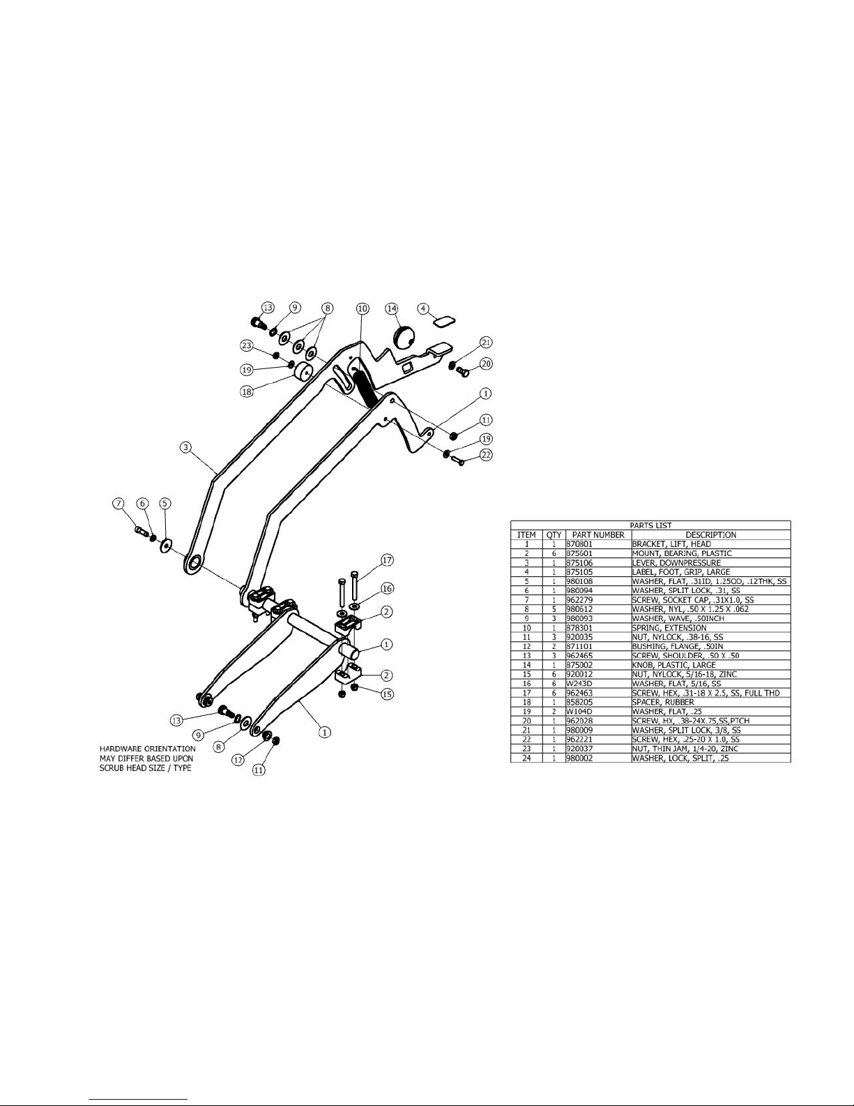
HEAD LIFT ASSEMBLY
Page 56
56
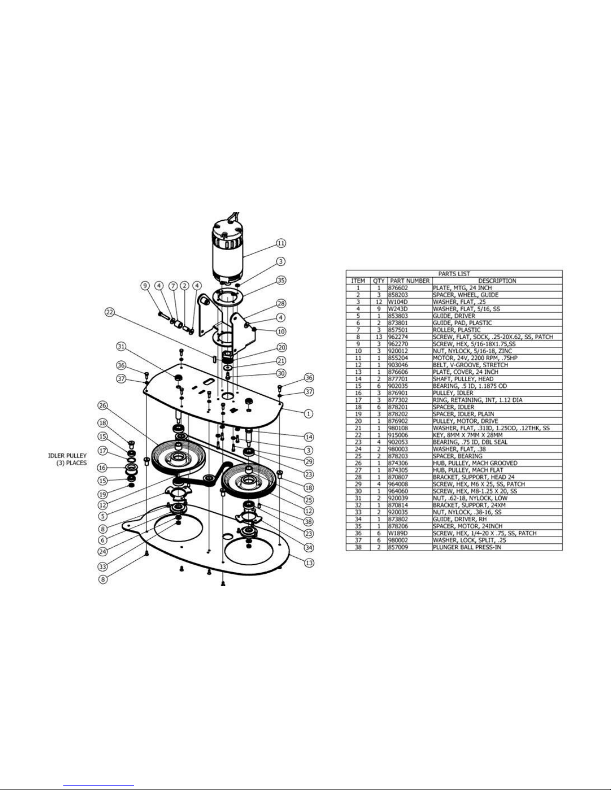
HEAD ASSEMBLY (DRAWING 1 OF 2), S-24
Page 57
57
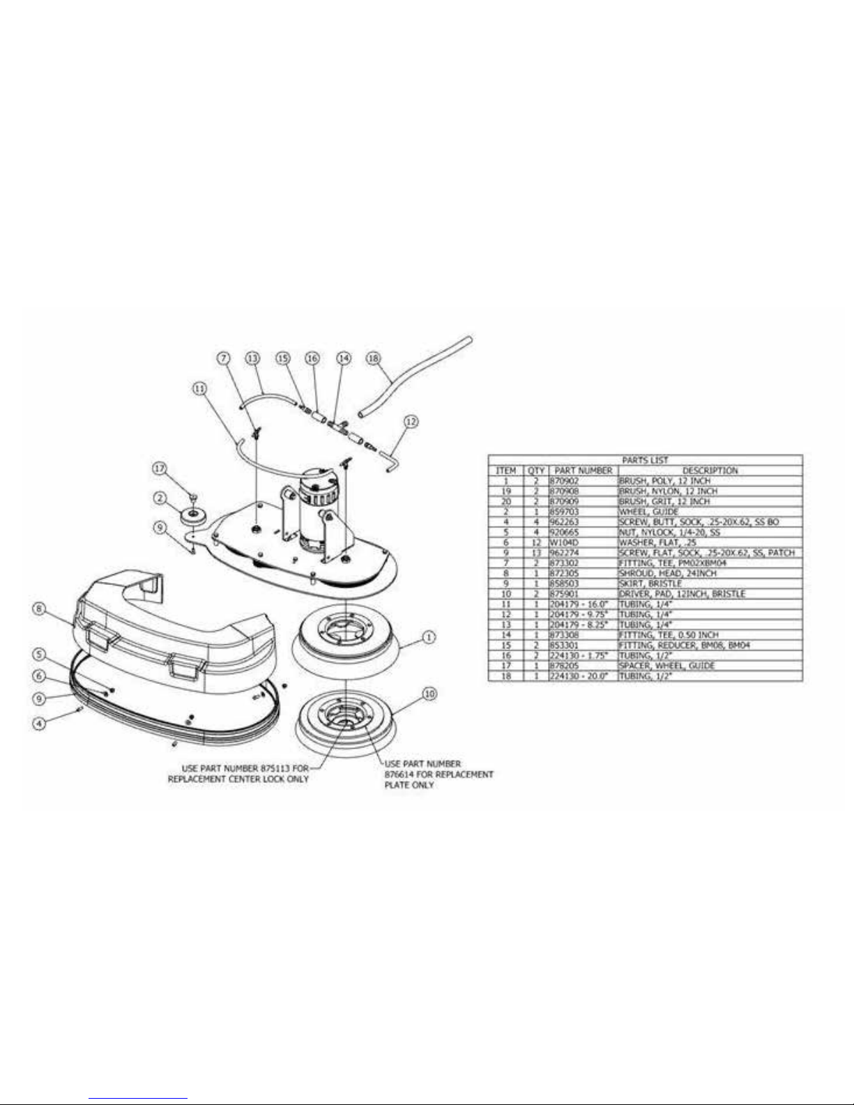
HEAD ASSEMBLY (DRAWING 2 OF 2), S-24
Page 58
58
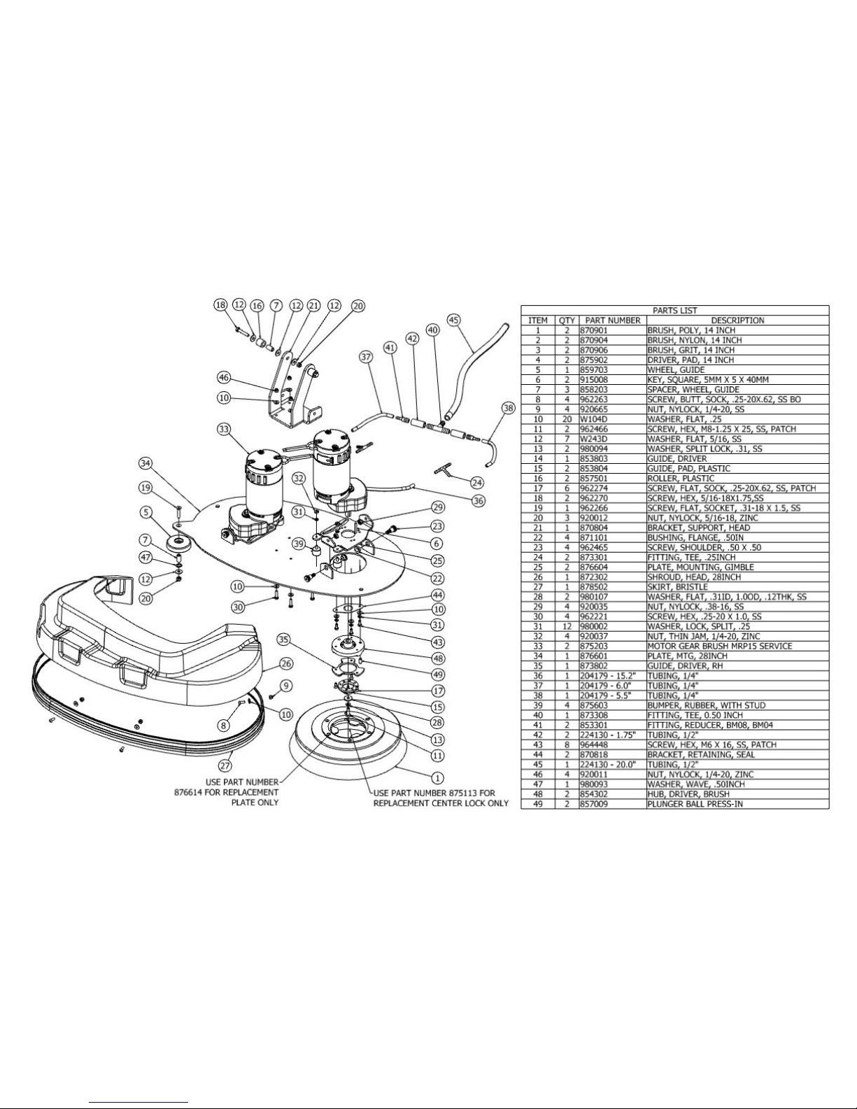
HEAD ASSEMBLY, S-28 DISK
Page 59
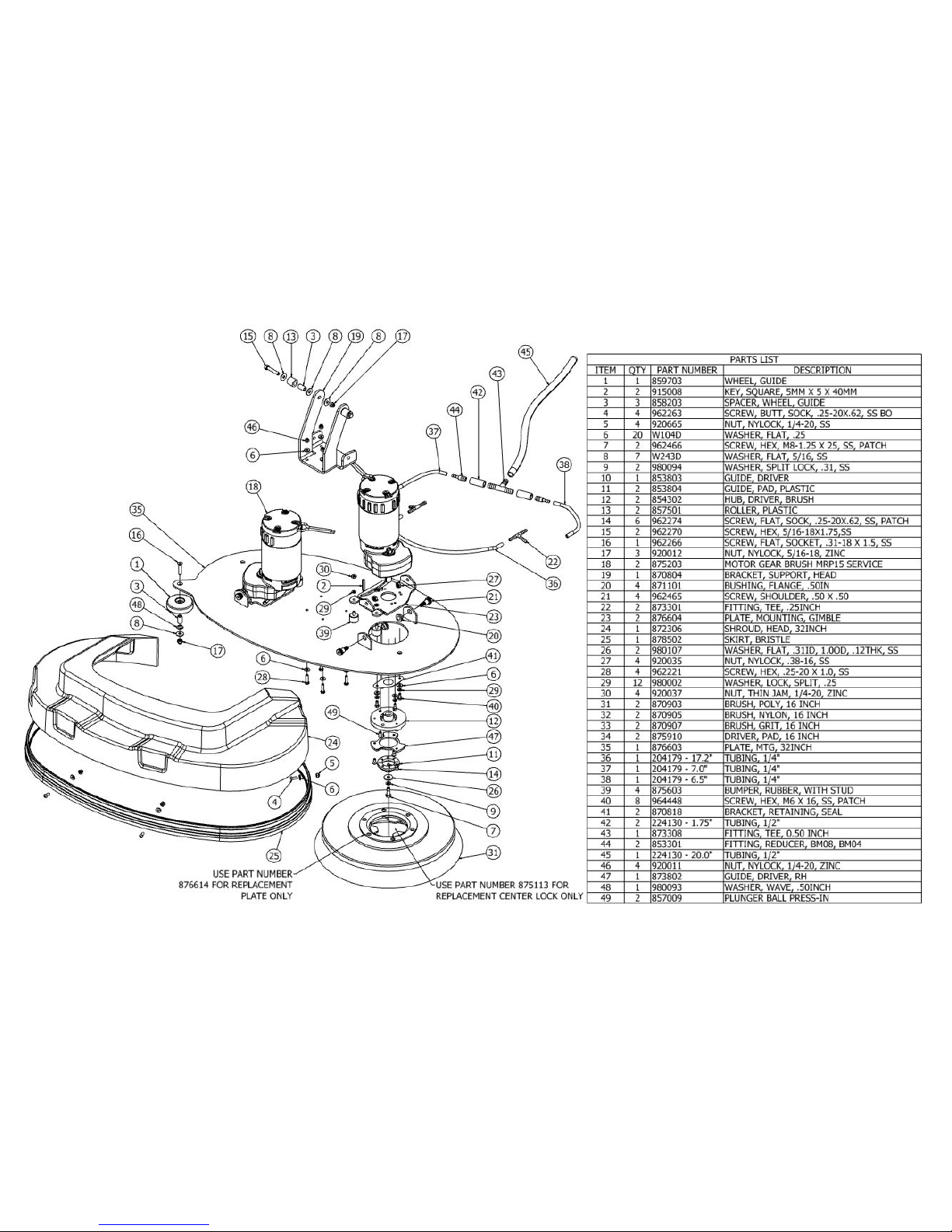
59
HEAD ASSEMBLY, S-32
Page 60
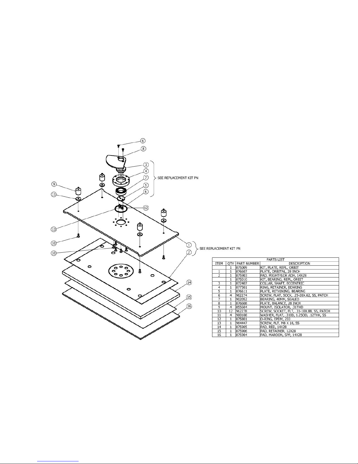
60
HEAD ASSEMBLY, LOWER, S-28 ORBITAL
Page 61
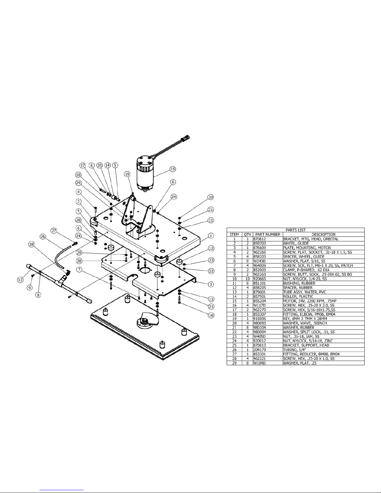
61
HEAD ASSEMBLY, UPPER, S-28 ORBITAL
Page 62
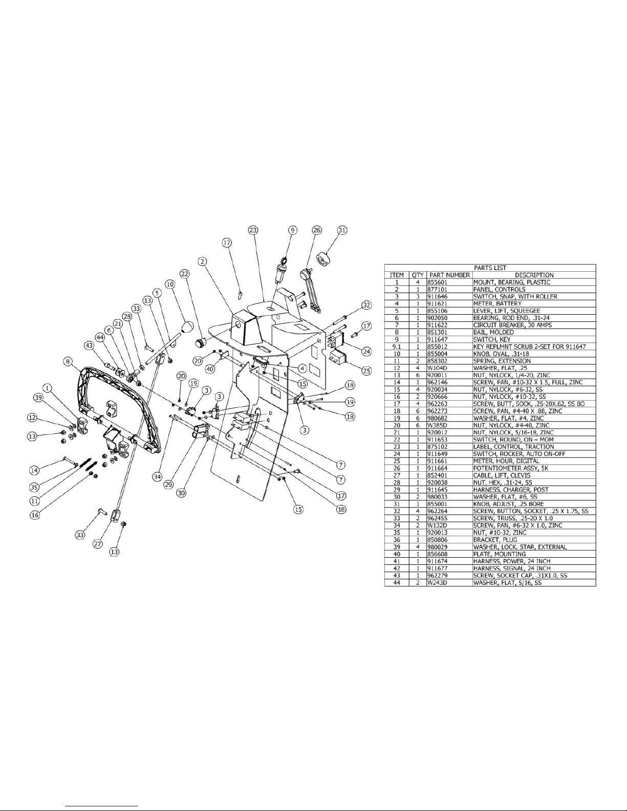
62
CONTROLS ASSEMBLY, S-24
Page 63
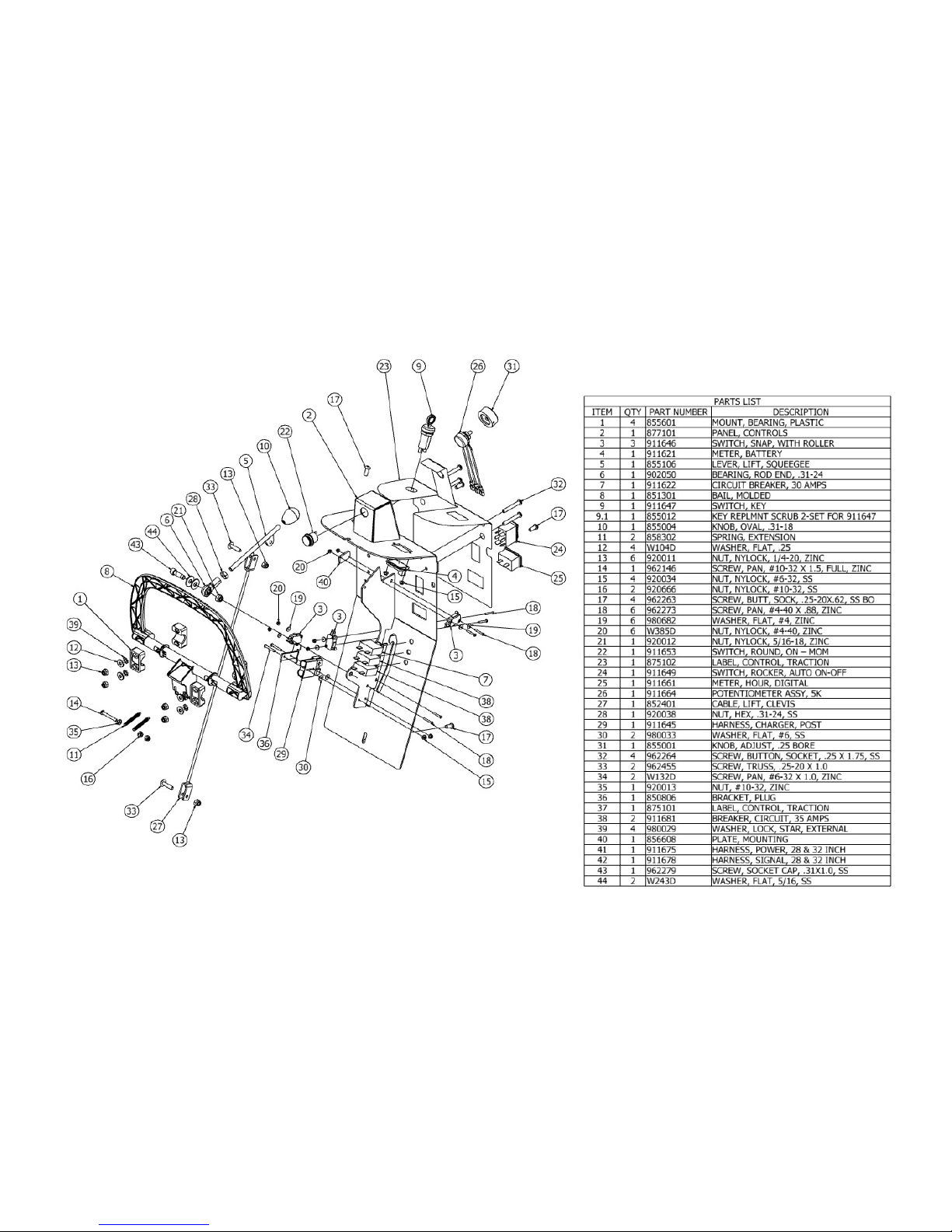
63
CONTROLS ASSEMBLY, S-28 & S-32 DISK
Page 64
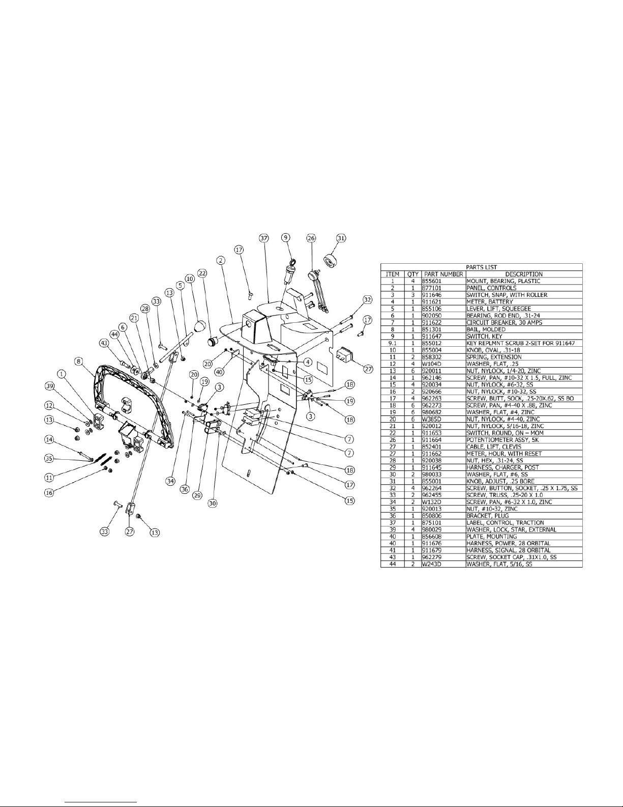
64
CONTROLS ASSEMBLY, S-28 ORBITAL
Page 65
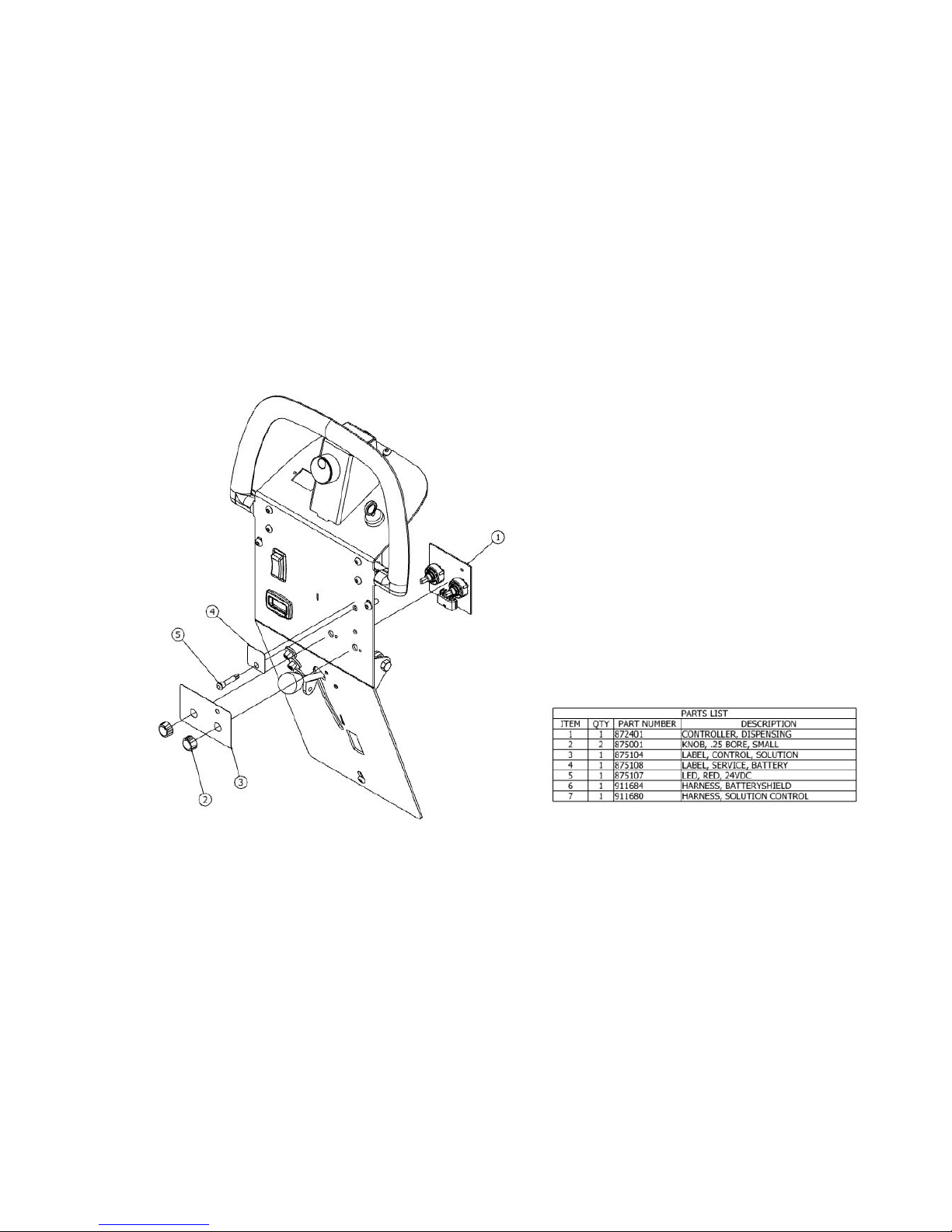
65
CONTROLS ASSEMBLY, BATTERYSHIELDTM & CHEMICAL INJECTION SYSTEM
(OPTIONAL)
Page 66
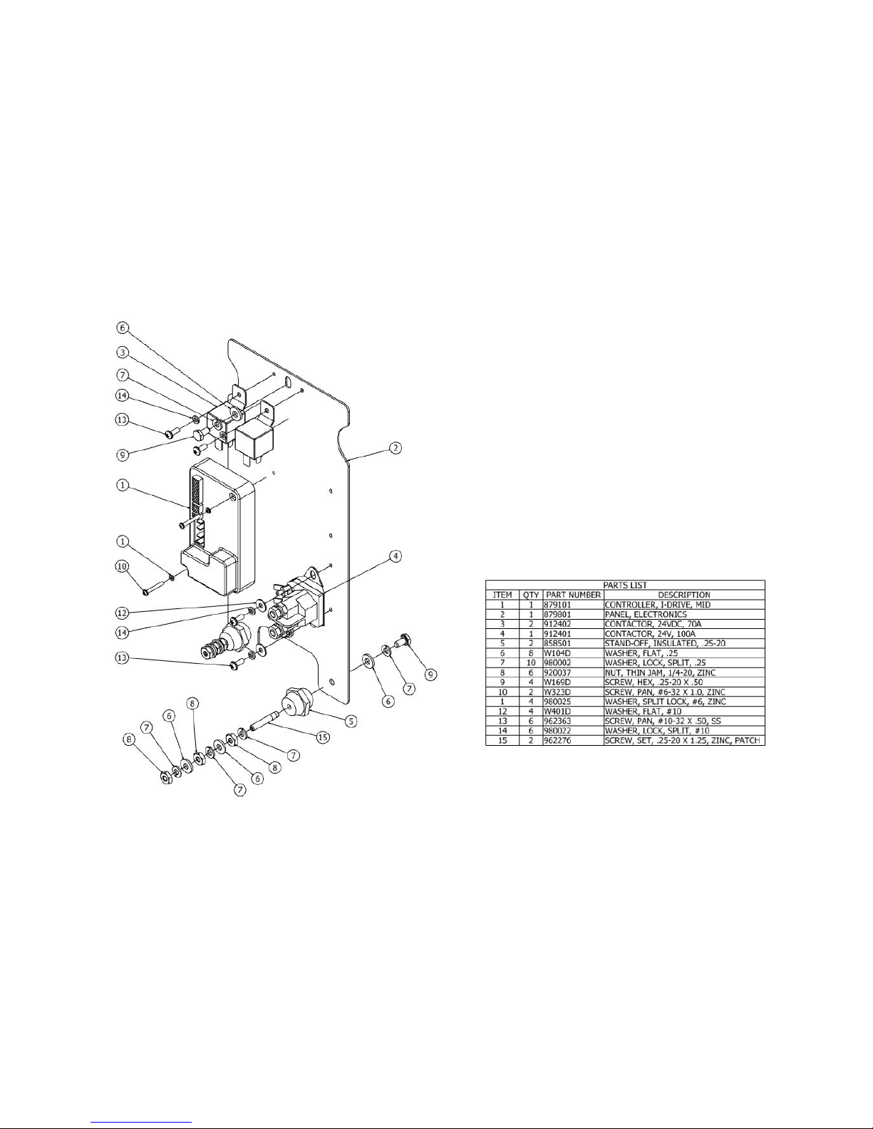
66
ELECTRONICS ASSEMBLY, S-24
Page 67
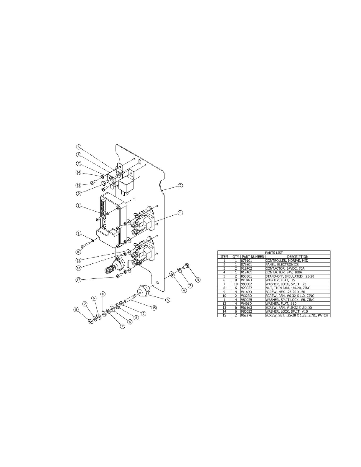
67
ELECTRONICS ASSEMBLY, S-28 & S-32 DISK
Page 68
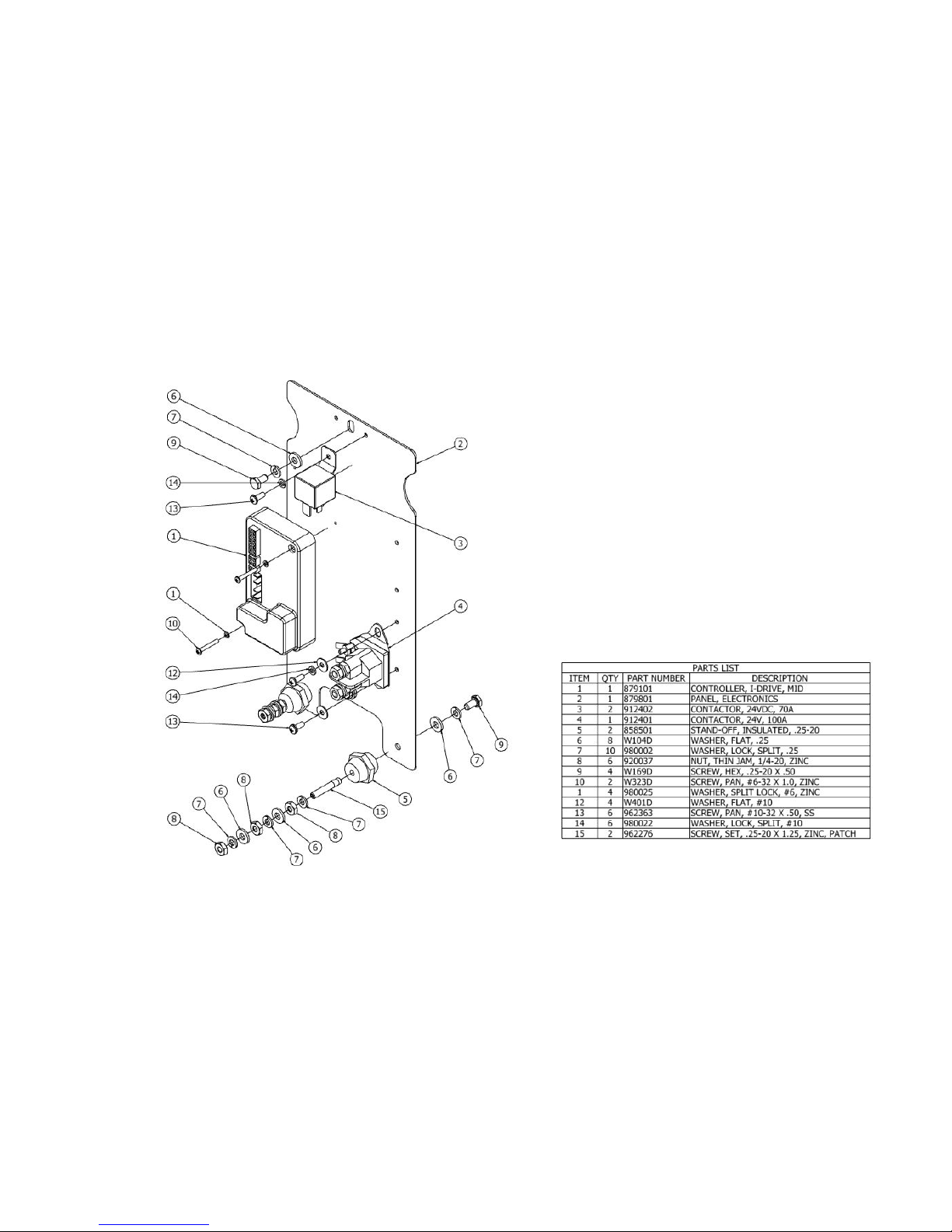
68
ELECTRONICS ASSEMBLY, S-28 ORBITAL
Page 69
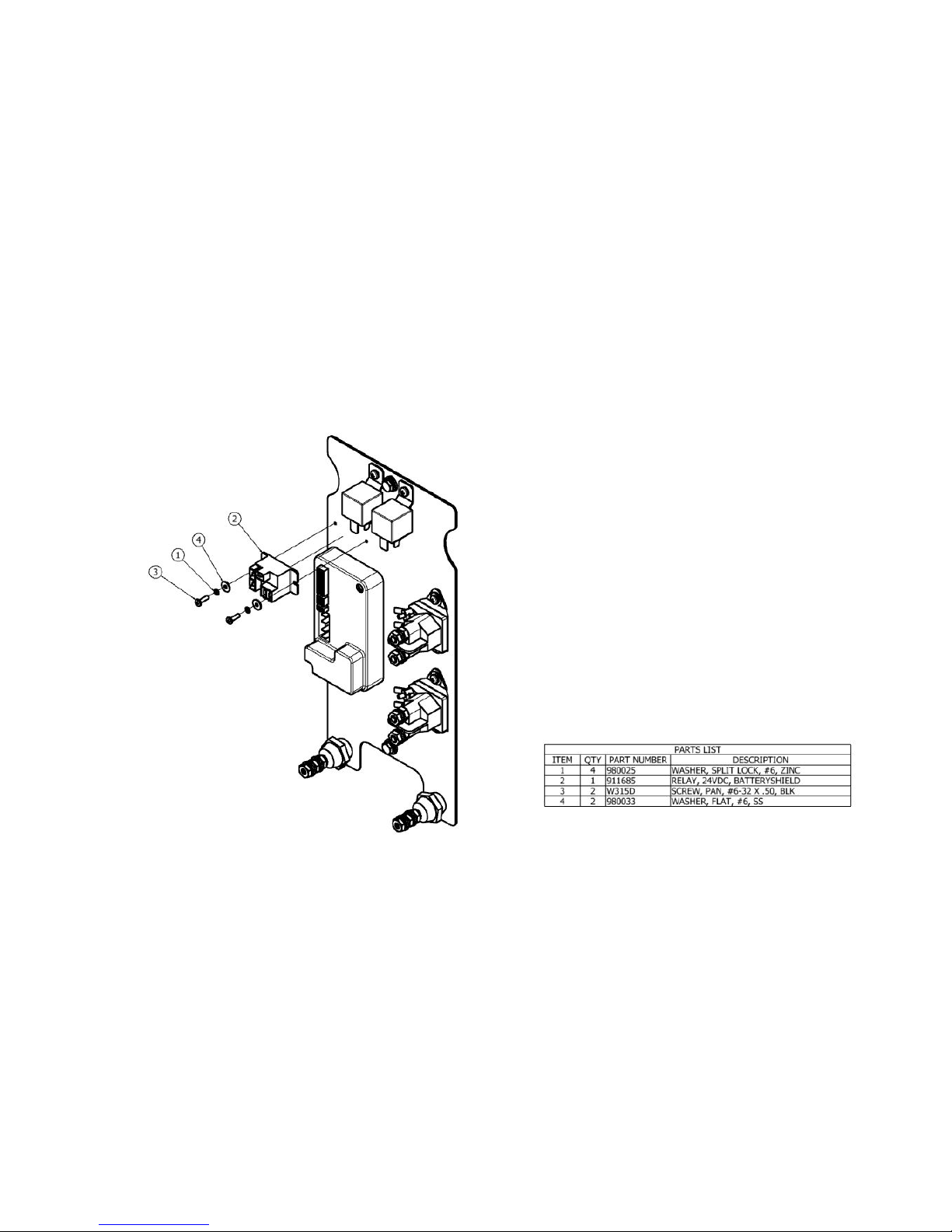
69
ELECTRONICS ASSEMBLY, BATTERYSHIELD
TM
Page 70
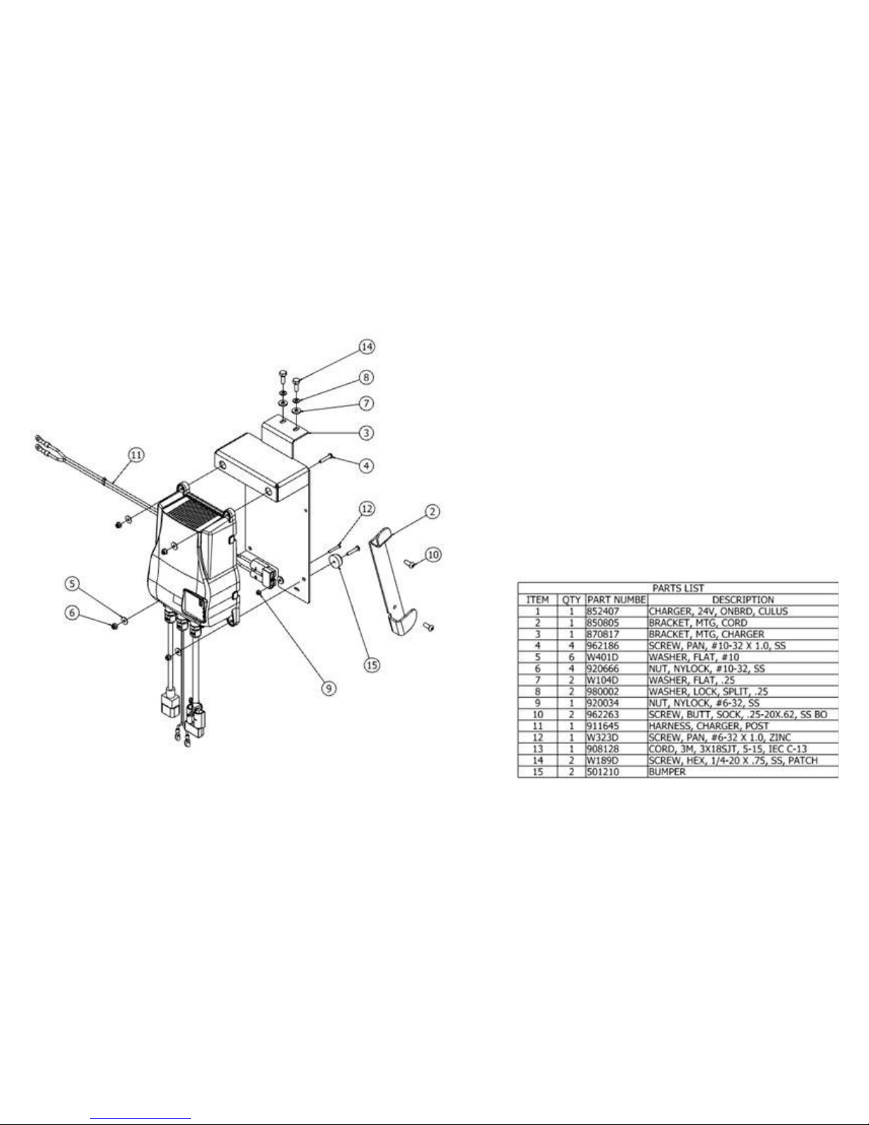
70
CHARGER ASSEMBLY, ON-BOARD
Page 71
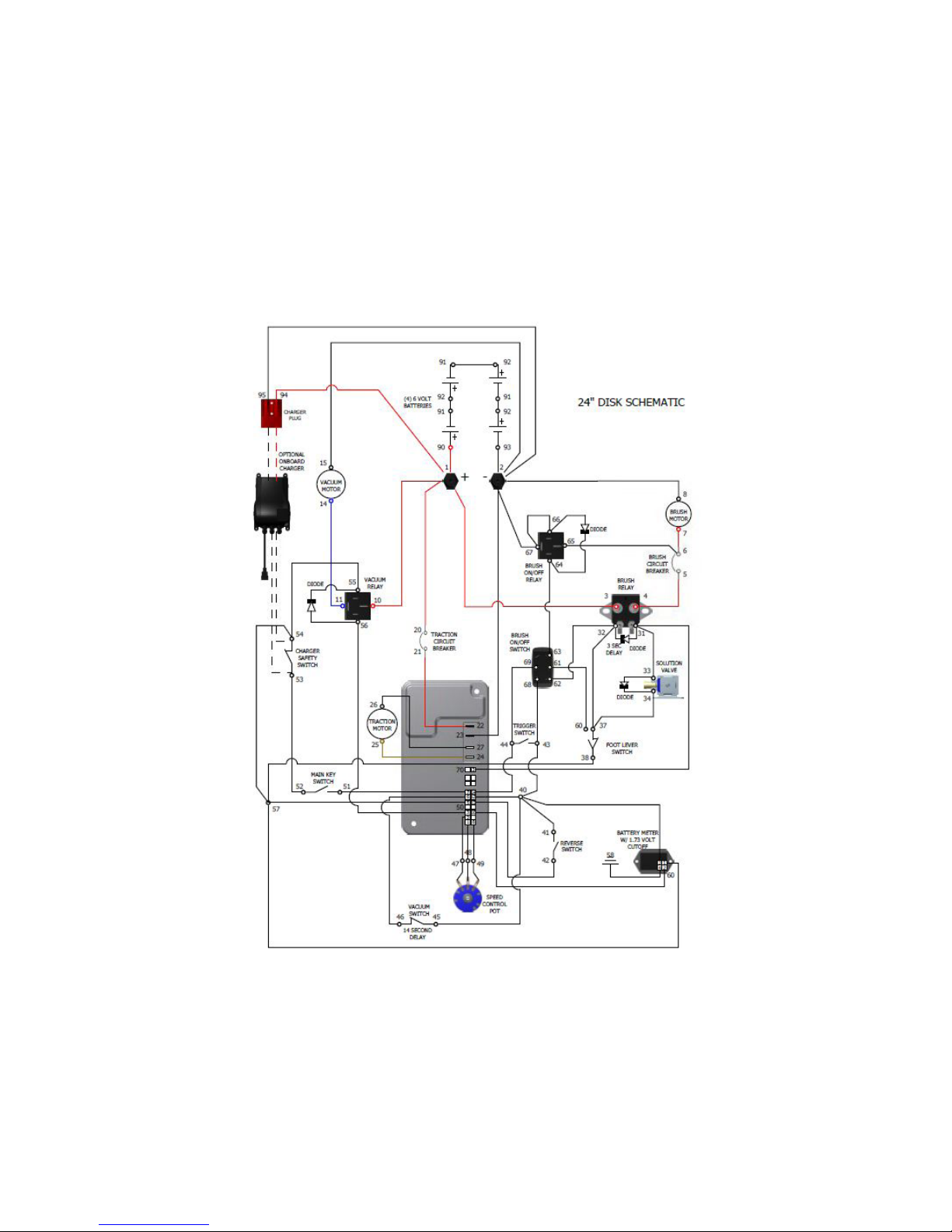
WIRING DIAGRAM, S-24
Page 72
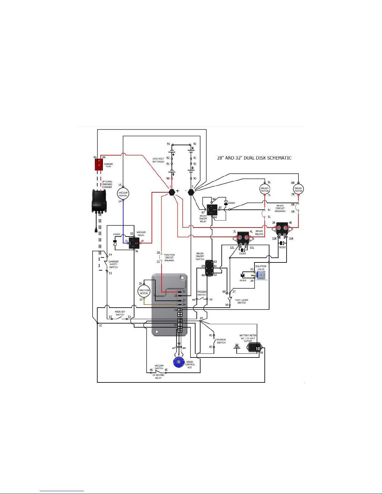
WIRING DIAGRAM, S-28 & S-32 DISK
Page 73
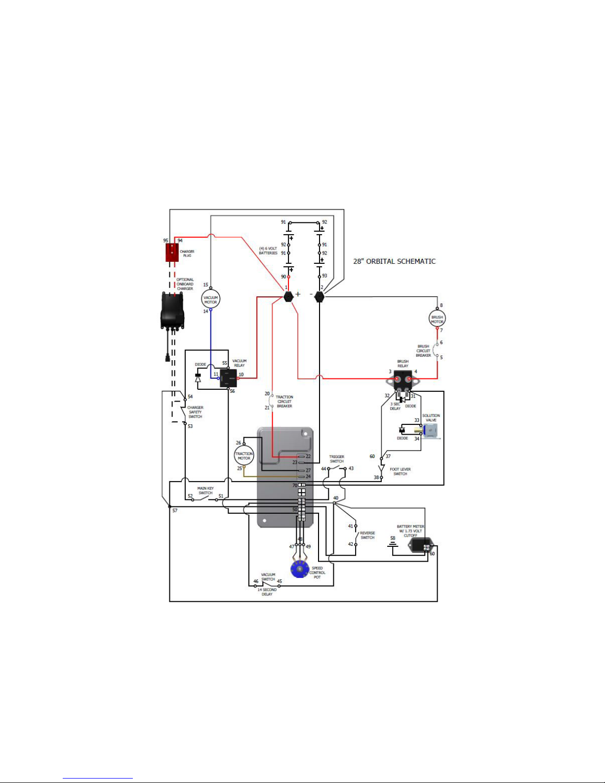
WIRING DIAGRAM, S-28 ORBITAL
Page 74
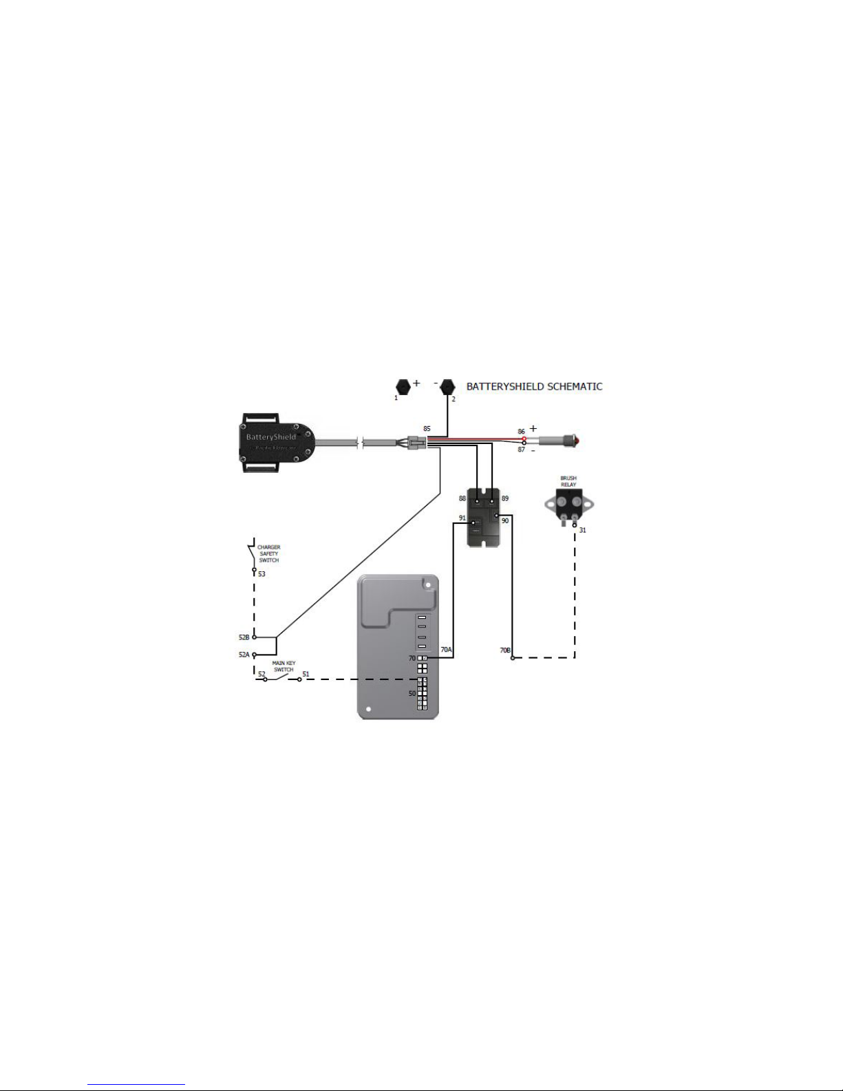
WIRING DIAGRAM, BATTERYSHIELD (OPTIONAL)
74
Page 75
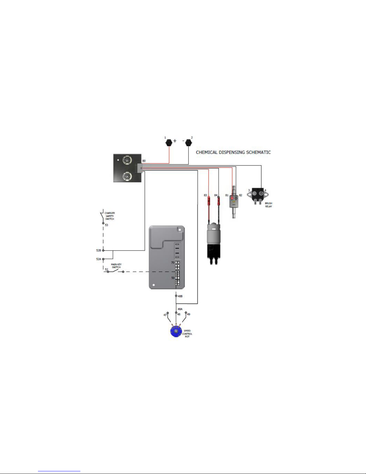
WIRING DIAGRAM, ON-BOARD CHEMICAL INJECTION SYSTEM (OPTIONAL)
75
Page 76

WARRANTY POLICY
S-SERIES MID-SIZE AUTO SCRUBBERS
The Pacic Floorcare S-Series mid-size auto scrubbers have been manufactured, tested and inspected in accordance with specic engineering requirements.
These machines are warranted to be free from defects in workmanship and materials for periods as follows from the date of purchase.
Travel time for warranty repair is authorized for a period of ninety (90) days following the date of sale to the end user, with a maximum of three (3) hours per claim.
This warranty extends to the original user/purchaser and only when used, operated and maintained in accordance with Pacic Floorcare Operating and
Maintenance instructions.
This warranty does not apply to certain wear parts and accessories of the machine such as carbon motor brushes, oor brushes or pad drivers, belts, hoses,
squeegee blades, etc., nor does it apply to damage or failure caused by improper use, abuse or neglect. Warranty credit or replacement of return parts including
motors, switches, etc., is subject to incoming inspection of those items.
To secure repair under this warranty, the following procedure should be taken:
1. After the expiration of the ninety (90) day travel time warranty period, the customer is responsible for warranty travel payment or the inoperative machine or
warranted parts must be delivered to the authorized dealer with shipping and delivery charges prepaid. If unable to locate the Dealer, you may contact Pacic
Floorcare at the address listed herein for the location of the nearest Pacic Floorcare repair center or agent or for other instructions pertaining to your warranty
difculty.
2. Upon compliance with the above warranty procedure, all warranted repairs will be completed at no additional charge or cost to the user.
3. Only Pacic Floorcare or its authorized dealers and agents may make no charge warranty repairs on this product. All others do so at their own risk.
This warranty limits Pacic Floorcare liability to the repair of the product and/or warranted parts replacement and does not include incidental or consequential
damages arising from the use of a Pacic Floorcare machine whether defective or not.
BATTERY WARRANTY
In addition to the terms above, any original equipment Pacic Floorcare Battery which becomes unserviceable under normal use within a period of ninety
(90) days from date of sale to the original user will be repaired or replaced with one of equal specication at our option, F.O.B. any authorized Pacic
Floorcare or Service Branch, with no charge to user, except transportation costs. After the expiration of the above ninety (90) day period, any battery which
fails under normal use will be adjusted to the original user with a new battery of equal specication on a twelve (12) month pro rata basis from the date of
purchase. Adjustment will be determined using the then current list price, plus transportation costs. Warranty is rendered null and void if battery
maintenance is not performed regularly.
This warranty is in lieu of all other expressed or implied warranties and is extended to the original purchaser/user.
Ten (10) Years - Rotationally molded components
Three (3) Years – Parts (excluding wear items)
Two (2) Years or 1,200 Hours - Isolators
One (1) Year – Labor
2259 S. SHERIDAN DRIVE
MUSKEGON, MICHIGAN 49442-6252
800-968-1332
FAX 800-863-9536
4/2016
 Loading...