

Page 1

UHS BURNISHERS
MODELS
PX-1500 & PX-2000
OPERATING & MAINTENANCE
INTRODUCTION INSTRUCTIONS
READ THIS BOOK
This operator’s book has important information for the use
and safe operation of this machine. Read this book carefully before starting the machine. Keep this book and tell
all operators to read the book. If you do not follow the
instructions, you can cause an injury or damage equipment,
furniture or buildings.
For new books write to:
Pacific Steamex, Inc.
2259 S. Sheridan
Muskegon, MI 49442-6252
Carefully inspect all components to ensure that there is no
concealed freight damage. If such damage is discovered,
file a “CONCEALED DAMAGE REPORT” immediately
with the delivering carrier.
The contents of this manual are based on the latest product
information available at the time of publication. Pacific
Steamex reserves the right to make changes or improvements to its machines without notice.
FOR YOUR CONVENIENCE, RECORD THE
FOLLOWING IMPORTANT INFORMATION:
MODEL_______________________________
SERIAL NUMBER______________________
PART NUMBER _________________________
DATE PURCHASED ______________________
Page 2
IMPORTANT SAFETY INSTRUCTIONS
To assure the safe operation of this machine, you must read and understand all warnings and instructions in this book. If you
do not understand, ask your supervisor.
READ ALL INSTRUCTIONS BEFORE USING THIS MACHINE
WARNING: To reduce the risk of fire, electric shock, or injury:
1. You must be trained to operate this machine. This machine is to be operated for its intended use only.
2. Do not operate this machine unless it is completely assembled.
3. Always use a three-wire electrical system connected to the electrical ground. For maximum protection against electrical
shock, use a circuit that is protected by a ground fault circuit interrupter. Consult your electrical contractor.
4. To prevent electric shock, always remove the electrical plug from the electrical outlet before doing any repairs or maintenance and when leaving the machine unattended.
5. To prevent electric shock, keep the machine surface dry. Do not subject to rain. Store the machine in a dry building area.
Clean the machine with a dry cloth only.
6. Machines can cause an explosion when near flammable materials and vapors. Do not use this machine with or near fuels,
grain dust, solvents, thinners, or other flammable materials. Do not use flammables to clean this machine.
7. A qualified or authorized person must do maintenance and repairs.
8. To prevent damage to the power cord, do not move this machine over the power cord. Always lift the power cord over the
machine. Do not pull or carry cord, use cord as a handle, close a door on cord, or pull cord around sharp edges or corners.
Keep cord away from heated surfaces.
9. Do not use with damaged cord or plug. If the machine is not working as it should, has been dropped, damaged, left
outdoors, or dropped into water, return it to a service center.
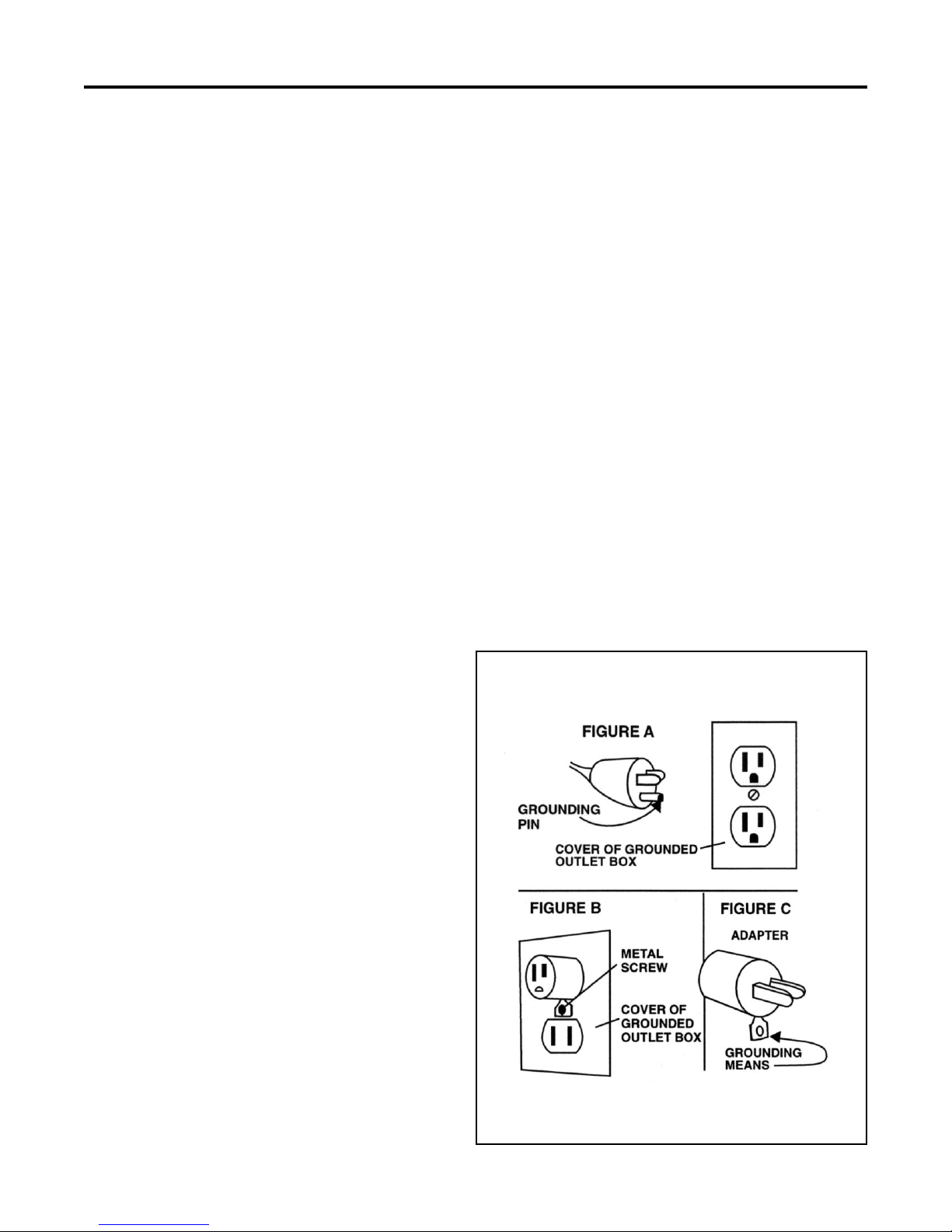
Grounding Instructions
This machine must be grounded. If it should malfunction or break down,
grounding provides a path of least resistance for electric current to reduce the
risk of electric shock. This machine is equipped with a cord having an equipment-grounding conductor and grounding plug. The plug must be inserted
into an appropriate outlet that is properly installed and grounded in accordance with all local codes and ordinances.
WARNING - Improper connection of the equipment-grounding conductor
can result in a risk of electric shock. Check with a qualified electrician or
service person if you are in doubt as to whether the outlet is properly grounded.
Do not modify the plug provided with the machine - if it will not fit the outlet,
have a proper outlet installed by a qualified electrician.
This machine is for use on a nominal 120-volt circuit, and has a grounded
plug that looks like the plug illustrated in figure A. A temporary adapter that
looks like the adapter illustrated in figures B and C may be used to connect
this plug to a 2-pole receptacle as shown in figure B if a properly grounded
outlet is not available. The temporary adapter should be used only until a
properly grounded outlet (figure A) can be installed by a qualified electrician. The green colored rigid ear, lug, or the like extending from the adapter
must be connected to a permanent ground such as a properly grounded outlet
box cover. Whenever the adapter is used, it must be held in place by a metal
screw.
NOTE: In Canada, the use of a temporary adapter is not permitted by the
Canadian Electrical Code
EXTENSION CORDS
Use only three-wire 12/3 or larger gauge approved extension cords that have
three-prong grounding type plugs and three-pole receptacles that accept the
appliance’s plug. Replace or repair any damaged cords or plugs.
When servicing, refer to authorized person only. Use only identical replacement parts.
NOTE: Do not use adapters shown in figures B & C in Canada
2
Page 3

OPERATING PROCEDURES
WARNING! For the safe operation of this machine follow the instructions given in this booklet and the training given by your supervisor. Failure to do so can result
in personal injury and/or damage to machine and property!
DO NOT OPERATE MACHINE IN AN EXPLOSIVE
ENVIRONMENT!
The models shown in this manual are intended for commercial use.
PREPARATION
To prepare the machine for operation, make sure it is of
correct voltage and properly assembled. If in doubt, ask
your supervisor.
Your new floor machine operates in a straight-line forward
motion, rather than the normal side to side motion of a
conventional single disc machine. Be prepared by having
your floor area cleared and ready for the fast action of a
burnisher.
Prepare the floor area by sweeping, dusting or mopping as
needed. Check the proper application recommendations
and procedures found on the label of your finish container.
IF IN DOUBT, CALL YOUR SUPERVISOR .
WARNING! NEVER USE THIS MACHINE WITH
FLAMMABLE OR EXPLOSIVE MATERIAL!
OPERATION
Set the machine upright onto the pad. Plug the machine’s
power cable into a properly grounded outlet (see Safety
Instructions). Next, release the handle locking knob and
allow the handle to lower into a comfortable position. Then
secure the handle locking knob. This will allow the operator to easily control the brush pressure.
Depress the handle slightly to elevate the pad from the floor.
This is to avoid burning the floor on initial start up, before
the operator is ready to move forward. Pull out on the
“Watch Dog” Safety Lock button and start the machine by
depressing either the left or right switch levers.
When you’re ready to move forward, lower the machine
head and pad to the floor and proceed forward in a straight
line, at a steady pace.
MAINTENANCE
AFTER EACH USE: Store the machine in a clean dry
area. Wipe the entire machine and cord down with a clean
cloth. Remove the pad and clean thoroughly. Wrap the
machine’s electrical cord onto the handles and the cord
hook provided. CHECK the cord and plug for nicks, cuts
or damage. Report these to your supervisor for correction.
WARNING! Always disconnect the machine’s electrical plug from the electrical outlet before performing any
service, maintenance, pad changing or inspection of the
machine.
For Burnishing: Select the correct clean floor pad (your
supplier can help you). The lighter color floor pads (buff or
white) are normally used for the burnishing procedure.
NEVER OPERATE THE MACHINE WITHOUT THE
FLOOR PAD INSTALLED!
It is very important to select clean, dry pads of uniform
thickness. Pads with high or low sections, or hard or soft
spots are unacceptable. Pads of open weave are recommended; because close weaves tend to load up fast, bog
down the machines, cause circuits to overload and generally give poor results.
Tip the machine back to expose the pad driver. Remove
the pad center lock ring. Carefully center the pad onto the
pad driver and secure with the locking ring. Check for
level, centering and flatness.
MOTOR: The motor is lubricated for life under normal
use. No oiling or greasing is necessary. However, if the
machine is used in dusty areas the motor should be cleaned.
Blowing the motor out with compressed air or with the
exhaust from a vacuum is suggested. Keeping the motor
clean will allow the clear passage of air for ventilation and
prevent overheating.
BELT TENSION: Proper belt tension is important for
smooth operation and belt life. Check the belt tension and
have no more than a 1/8-inch deflection. If adjustment is
needed, loosen the four (4) motor mounting bolts. Then
turn the belt tension adjustment screw (located at the rear
of the chassis) clockwise to tighten or counter-clockwise to
loosen the belt. Tighten the four (4) motor mounting bolts.
CARBON BRUSH INSPECTION: Long life 3000-hour
carbon brushes are installed in the motor. The machine is
also equipped with a carbon brush wear indicator light to
signal when a carbon brush change is required.
3
Page 4
4
Page 5
PX-1500 & PX-2000
.
V
V
Parts List
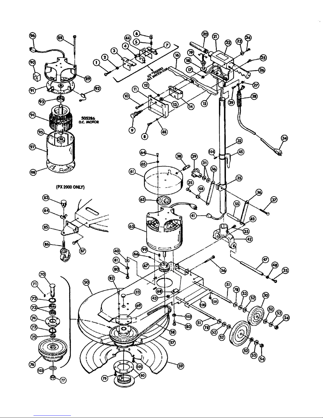
ITEM PART NO. DESCRI P T I ON QTY.
1 W323D Screw , 6-32x1 Pan Hd. 2
2 980016 Washer, #6 Ext. Tooth 2
3 500801 Bracket, Sw itch Mounting 1
4 911135 Sw itch 1
5 508301 Spring 1
6 507001 Plunger 1
7 500802 Bracket, Sw itch 1
8 962002 Screw , 10-32 x 1/2 Oval Hd. 2
9 504810 Interlock Asm.-Sw itch 1
10 962011 Screw , 10-32 x 3/4 Oval Hd. 2
11 486404 Sw itch Cover Plate 1
12 509821 Washer, Rubber 2
13 920005 Nut, 3/8-24 Hex 1
14 505003 Sw itch A ssembly 1
15 505121 Lever, Sw itch Left 1
16 505120 Lever, Sw itch Right 1
17 920001 Nut, 10-32 Elas tic Stop 1
18 509830 Washer, Handle Tube 1
19 503320 Flange, Strain Relief 1
20 505720 Handle Nipple 2
21 481304 Sw itch Housing,w /o Circuit Brkr
22 515150 Warning Label 1
23 501210 Bumper, Handle 1
24 962003 Screw , 10-32 x 3/4 Pan Hd. 1
25 962006 Screw , 1/4-20 x 1/2 Pan Hd. 7
26 503711 Handle Grip, Grey 2
501501 Cap, Protec tive End (Blue) 2
27 980015 Washer, #10 Shakeproof 2
28 508520 Strain Relief-Complete 1
502020 Strain Relief-Brass Clamp 1
29 962015 Screw , 10-32 x 3/8 Pan Hd. 2
30 509781 Wheel, 5" 4
31 980007 Washer, 5/16 Flat 2
32 509082 Handle Tube 1
33 S799NP Plug 1
34 502421 Cord As m.Grey 1
35 502021 Clamp-Handle 1
36 500880 Ar m, Handle Support 2
37 962009 Bolt, Carriage 5/16-18 x 2-1/2 1
38 505181 Light-Brush Wear Indicator 115
505182 Light-Brush Wear Indicator 230
39 505010 Turn Knob 1
40 980003 Washer, 3/8 Flat 3
41 908004 Handle Cord 1
42 509920 Yoke, Handle 1
43 920012 Nut, 5/16-18 ESNA Lock 1
1
1
1
ITEM PART NO. DESCRIP TION QTY.
44 504702 Insulator, Sw itch 1
45 504420 Cord Hook 1
46 980018 Washer, #10 Countersunk 1
47 487701 Shaf t, Handle Yoke 1
48 980002 Washer, 1/4 Lock 3
49 507310 Snap Ring 1
50 483212 Base (1500) 1
483213 Base (2000) 1
51 487703 Wheel Axle 2
52 980005 Washer, Wave 8
53 509820 Washer, Fiber 8
54 S482P Snap Ax le Cap 4
55 507481 Rod, Brace 1
56 W370D Screw , 5/16-18x3-3/4 (1500) 1
W375D Screw , 5/16-18x3-1/4 (2000) 1
57 481204 Bumper Base 1
58 962 Belt (1500) 1
1404 Belt (2000) 1
59 515904 Pad Asm. Flex Drive 1
60 504470 Holder Asm.-Pad 1
61 502396 Cover, Motor 1
62 509823 Washer, Felt 3/16 x 3 1
63 505286 Motor, 1.5 HP 115V DC IMP 1
505278 Motor, 1.5 HP 230V DC IMP 1
64 962026 Screw , 8-32 x 1/2 3
65 980013 Washer 1
66 W168D Set Screw 1
67 1494 Pulley Motor (1500) 1
1406 Pulley Motor (2000) 1
68 1451 Belt Tightener 1
69 1008 Spacer 1
70 1405 Drive Shaft 1
71 1400 Woodruff Key 1
72 139 Snap Ring 2
73 143 Bearing, Drive Shaft 2
74 1416 Bearing Housing 1
75 1401 Spacer, Drive Shaft 1
76 1460 Pulley Pad (1500) 1
1389 Pulley Pad (2000) 1
77 W204D Nut, 5/8-18 Hex 1
78 W120D Washer, 7/16 Flat 4
79 962076 Screw , #8 x 5/8 Pan Hd. 3
80 W504D Screw , 3/8-16 x 3/4 HH 4
81 980009 Washer, 3/8 Lock 3
82 W189D Screw , 1/4-20 x 3/4 HH CS 4
5
Page 6
6
Page 7
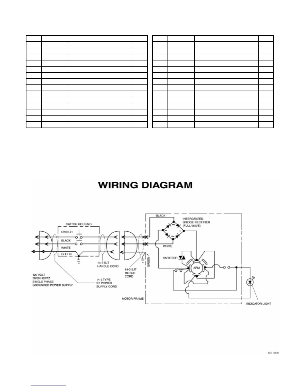
PX-1500 & PX-2000
Parts List
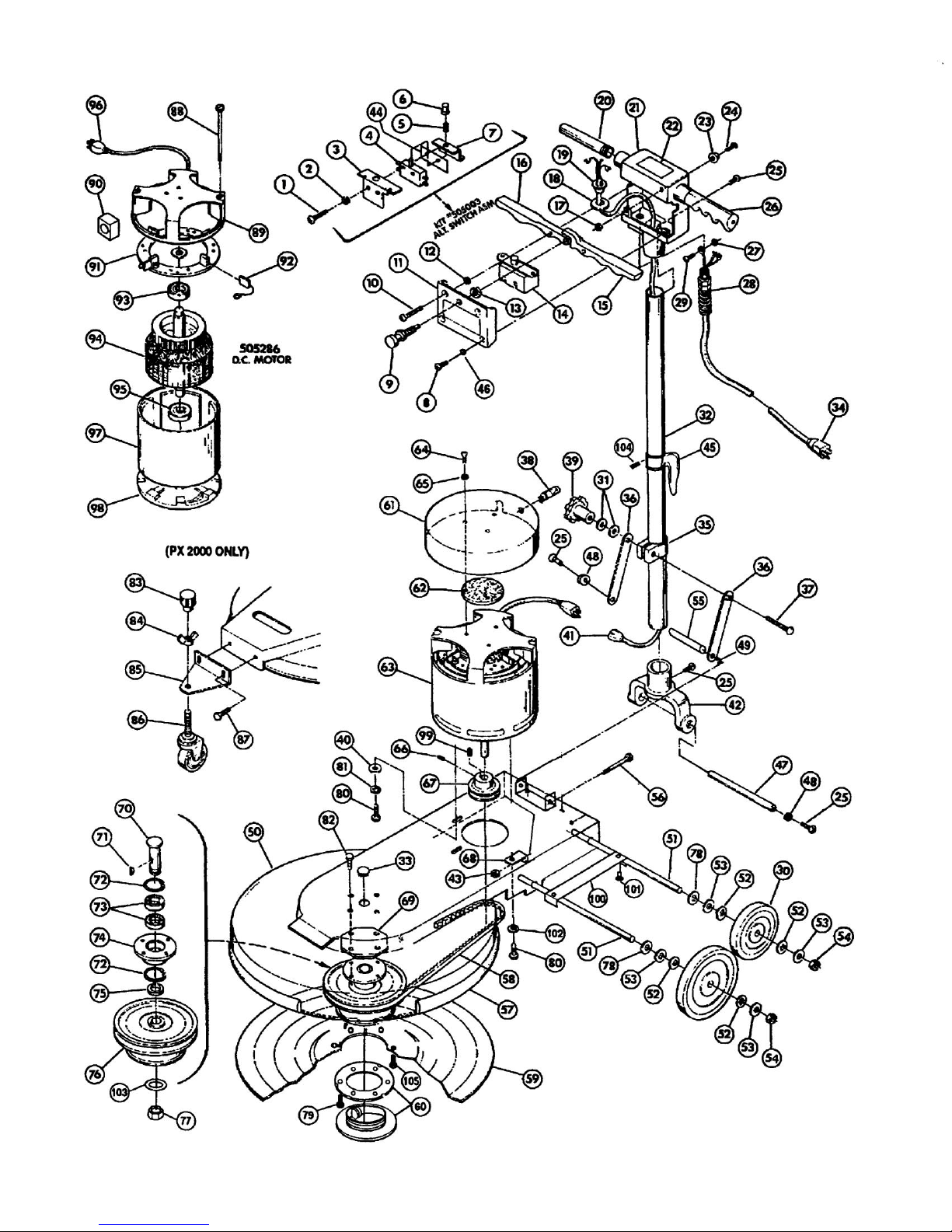
ITEM PART NO. DESCRIPTION QTY.
83 1481 Knob, Caster Adjustment (2000) 1
84 W517D Nut, 3/8-16 W ing Zinc (2000) 1
85 480803 Bracket, Caster (2000) 1
86 519701 Caster (2000) 1
87 W169D Screw, 1/4-20 x 1/2 HH (2000) 2
88 960018 Bolt-Motor Thru 4
89 502920 End Bell Motor Top 115V 1
502930 End Bell Motor Top 230V 1
90 911048 Rectifier-Bridge 115V 1
911081 Rectifier-Bridge 230V 1
91 507322 Brush Ring Asm. Complete 115V 1
507326 Brush Ring Asm. Complete 230V 1
92 500903 Brush, Carbon Motor 115V 4
510901 Brush, Carbon Motor 230V 4
ITEM PART NO. DESCRIPTION QTY.
93 902003 Bearing-Motor Top 1
94 500417 Armature 115V 1
500424 Armature 230V 1
95 902012 Bearing-Motor Lower 1
96 908024 Cord Asm. 1
97 503117 Field/Shell Asm. 1
98 502919 End Bell Lower 1
99 1408 Key-Motor 1
100 487201 Retainer, Axle 1
101 962016 Screw, 10-32 x 3/8 Set 2
102 980021 W asher, 3/8 Int. Tooth 1
103 980074 W asher, 5/8 Int. Tooth 1
104 962005 Screw, 1/4-20 x 3/8 Allen 1
105 W378D Screw, 1/4-20 x 3/4 FH 6
7
Page 8

WARRANTY POLICY
UHS BURNISHERS, MODELS PX-1500 & PX-2000
The Pacific Steamex Inc. UHS Burnisher has been manufactured, tested and inspected in accordance with specific engineering requirements and is WARRANTED to be free from defects in workmanship and materials as follows:
Three (3) years parts, One (1) year labor - Castings and DC Motors (except motor switches, rectifiers, carbon brushes and
varsitors)
One (1) year parts and labor – All other components unless excluded below.
This warranty extends to the original user/purchaser and only when used, operated and maintained in accordance with Pacific
Steamex Inc. Operating and Maintenance instructions.
This warranty does not apply to the following wear parts and accessories of the machine including:
Part Number Part Name
502421 Cord Assembly
509781 Wheel
503711 Handle Grip, Grey
481204 Bumper Base
962 Belt (1500)
1404 Belt (2000)
519701 Caster (2000)
500903 Carbon Brush, 115V Motor
510901 Carbon Brush, 230V Motor
Nor does it apply to damage or failure caused by improper use, abuse or neglect. Warranty credit or replacement of return parts
including motors, etc., is subject to incoming inspection of those items.
To secure repair under this warranty, the following procedure should be taken:
• The inoperative machine or warranted parts must be delivered to the authorized dealer with shipping and delivery charges
prepaid. If unable to locate the Dealer, you may contact Pacific Steamex Inc. at the address listed herein for the location
of the nearest Pacific Steamex Inc. repair center or agent or for other instructions pertaining to your warranty difficulty.
• Upon compliance with the above warranty procedure, all warranted repairs would be completed at no additional charge or
cost to the user.
• Only Pacific Steamex Inc. or its authorized dealers and agents may make no charge warranty repairs on this product. All
others do so at their own risk.
This warranty limits Pacific Steamex Inc. liability to the repair of the product and/or warranted parts replacement and does
not include incidental or consequential damages arising from the use of a Pacific Steamex Inc. machine whether defective or
not.
This warranty is in lieu of all other expressed or implied warranties and is extended to the original purchaser/user.
08/01 485602
PACIFIC STEAMEX, INC.
2259 S. SHERIDAN
MUSKEGON, MICHIGAN 49442-6252
800-968-1332
FAX 800-863-9536
 Loading...