


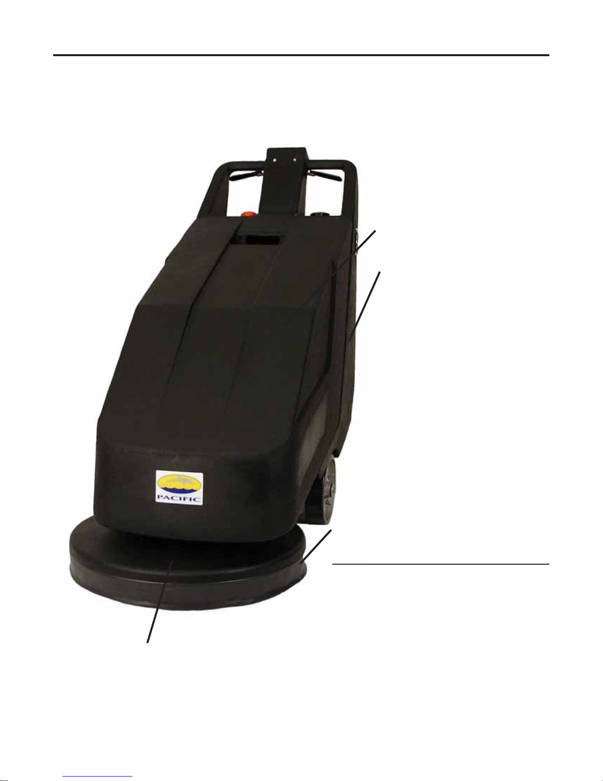
FURY 20BB
20” Battery
Burnisher
OPERA TING & MAINTENANCE
INTRODUCTION INSTRUCTIONS
READ THIS BOOK
This operator’s book has important information for the use
and safe operation of this machine. Read this book carefully before starting the machine. Keep this book and tell all
operators to read the book. If you do not follow the instructions, you can cause an injury or damage equipment, furniture or buildings.
For new books write to:
Pacific Steamex, Inc.
2259 S. Sheridan
Muskegon, MI 49442-6252
Carefully inspect all components to ensure that there is no
concealed freight damage. If such damage is discovered,
file a “CONCEALED DAMAGE REPORT” immediately with
the delivering carrier.
The contents of this manual are based on the latest product
information available at the time of publication. Pacific
Steamex reserves the right to make changes or improvements
to its machines without notice.
FOR YOUR CONVENIENCE, RECORD THE
FOLLOWING IMPOR TANT INFORMA TION:
MODEL
SERIAL NUMBER
P ART NUMBER
DA TE PURCHASED

IMPORT ANT SAFETY INSTRUCTIONS
READ AND UNDERSTAND ALL WARNINGS AND INSTRUCTIONS
BEFORE USING THIS MACHINE!
WARNING! To reduce the risk of fire, electric shock, or injury:
1. You must have training in the operation of the machine before using it. READ THE INSTRUCTION
BOOK AND CHARGER MANUAL. If you do not understand any instruction, ask your supervisor.
2. Make sure all labels, decals, warnings, cautions and instructions are fastened to the machine.
3. Read the labels carefully on the machine. Do not cover them for any reason and replace them if damaged.
4. Do not operate this machine unless it is completely assembled. Inspect the machine carefully before operation.
5. Pay close attention to other people and especially children while operating this machine.
6. Be a careful operator, do not strike shelving or scaffolding, especially where there is a danger of falling
objects.
7. Machines can cause an explosion when operated near flammable materials and vapors. Do not use this
machine with or near fuels, grain dust, solvents, thinners or other flammable materials.
8. In case of fire, use a powder extenguisher.
9. Do not use machine as a means of transport.
10. Do not use acid solutions that could damage the floor.
11. Adjust your speed to the conditions of the floor .
12. Do not turn the machine on a ramp. Do not stop and leave the machine on a ramp or incline.
13. When the machine is parked, move switch to the OFF position (red button switch pressed down all the way).
14. During any maintenance operation, disconnect the power supply from the machine.
15. Lead acid batteries generate gases that can cause an explosion. Read the instruction manual supplied with
the battery charger. Keep sparks and flames away from batteries. NO SMOKING. Charge the batteries
only in an area with good ventilation.
16. Do not use a charger if the power cord is damaged.
17. Always wear eye protection and protective clothing when working near batteries. Remove all jewelry. Do
not put tools or other metal across the battery terminals or the tops of the batteries.
18. Maintenance and repairs must be performed by Authorized Service Centers only. Make adjustments
according to the specifications given in the manual for this machine.
19. Keep the electrical parts of the machine dry. Do not wash the machine with direct water jets or high
pressure, nor with corrosive material. For storage, keep the machine in a dry building.
20. Always put CAUTION signs near the area where you are working.
21. Do not reach under shrouds with fingers, hands or toes when the machine is running.
Do not use water.
2

OPERA TING INSTRUCTIONS
W ARNING! For the safe operation of this machine follow
the instructions given in this booklet and the training given
by your supervisor . Failure to do so can r esult in personal
injury and/or damage to machine and property!
DO NOT OPERATE MACHINE IN AN EXPLOSIVE
ENVIRONMENT!
The model shown in this manual is intended for commercial
use.
PREPARATION
T o prepare the machine for operation, make sure the
batteries are charged and the machine is properly assembled. If in doubt, ask your supervisor.
Be prepared by having your floor area cleared and ready
for the fast action of a burnisher.
Prepare the floor area by sweeping, dusting or mopping as
needed. Check the proper application recommendations
and procedures found on the label of your finish container. IF IN DOUBT , CALL YOUR SUPER VISOR.
W ARNING! NEVER USE THIS MACHINE WITH
FLAMMABLE OR EXPLOSIVE MA TERIAL!
PAD INSTALLA TION
For Burnishing: Select the correct clean burnishing pad
(your supplier can help you). Make sure that the pad is for
ultra high speed burnishing.
NEVER OPERA TE THE MACHINE WITHOUT THE
FLOOR P AD INSTALLED!
It is very important to select clean, dry pads of uniform thickness. Pads with high or low sections or hard or soft spots
are unacceptable. Pads of open weave are recommended
because close weaves tend to load up fast, bog down the
machines, cause circuits to overload and generally give poor
results.
1. Lift the pad assembly off the floor by lifting lever . Lock in
full “up” position.
2. Unscrew the Pad Retainer by turning it clockwise (when
viewing bottom of pad).
3. Install or replace the pad.
4. Center the new pad on the Pad Driver .
5. Screw the Pad Retainer back on by turning it counter clockwise (when viewing bottom of pad). Check and re
tighten periodically as Pad Retainer may loosen during
operation.
BA TTER Y INSTALLATION
1. Make sure the Red On/Off Switch is in the OFF
position (pushed completely down).
2. Lift and remove the Upper Hood Cover .
3. Place the batteries in their compartment and follow the
“Under Hood Electrical Connections” Drawing on
page 5.
BA TTER Y CHARGING
1. Insure that you have the proper charger or charger
setting for your type of batteries, either conventional
wet, lead acid or sealed “maintenance free”, gel cell/
AGM batteries.
2. Read and follow the charger instructions.
3. Move the Red On/Off to the OFF position (pushed
completely down).
4. Lift and remove the Upper Hood Cover .
5. Connect the charger plug into the mating plug on the
machine. It is located at the rear of the machine.
W ARNING! NEVER ALLOW THE BA TTERIES T O
RUN COMPLETEL Y DOWN, rechar ge them when the
Battery Condition Meter reading is on “RECHARGE”.
6. Plug the charger into a grounded outlet that has the
proper voltage.
W ARNING! NEVER TURN THE MACHINE ON WHILE
CHARGING!
OPERA TION
1. Make sure the pad is on and attached properly. See “Pad
Installation”.
2. Reduce the pad pressure by turning the Caster Knob
clockwise.
3. Move the Switch to the ON position (pulled completely
up), the Green Indicator Light will come on.
4. Check the Battery Condition Meter before operating.
The meter should be in the “W orking Range”.
5. Squeeze one or both Switch Levers and start burnishing
by pushing machine in a slow and steady path. Keep
machine moving while pad is on or floor damage will
occur!
6. Check the Load Meter for PROPER PAD PRESSURE:
A. With machine turned on and levers in the operating
position, check Load Meter for pressure:
1. White area - pressure is too low
2. Green area - pressure is good
3. Red area - pressure is too high
B. To adjust to desired pressure:
1. Turn Caster Knob clockwise to raise pad and
decrease pressure.
2. Turn Caster Knob counter-clockwise to lower pad
and decrease pad pressure.
C. For the best performance, the Load Meter should be
kept in the “Green” area. A green arrow above the
Green area indicates the best pressure.
6. After charging the batteries, disconnect the charger
from the outlet and machine. See battery maintenance on
page 4.
NOTE: T oo much pad pressure may trip the cir cuit breaker .
See “Resetting the circuit breaker” on page 4.
3

MAINTENANCE & TROUBLE SHOOTING
PREVENT ATIVE MAINTENANCE
W ARNING! Always move the On/Off Switch to the OFF
position (pushed all the way down) before performing any
service, maintenance, pad changing or inspection of the
machine.
After each use:
1. Empty the filter bag
2. Check the filter bag for rips.
3. Remove the pad and clean thoroughly.
4. W ipe the entire machine down with a clean cloth.
5. Store the machine inside in a clean, dry area.
Weekly:
1. For conventional, wet, lead acid batteries: Check the
level of the electrolyte in the batteries.
Maintain the proper electrolyte level by adding distilled
water when necessary . Electrolyte levels lower during
discharge and rise during charge. Therefore, it is
mandatory that water be added to cells ONL Y when they
are fully charged; do not overfill. Old batteries require
more frequent additions of water compared to new
batteries. DO NOT ATTEMPT TO OR REMOVE VENT
CAPS ON SEALED, “MAINTENANCE FREE”, GEL
CELL OR AGM BA TTERIES. W A TER CAN NOT BE
ADDED TO THOSE TYPE OF BATTERIES. DAMAGE
WILL OCCUR AND W ARRANTY WILL BE VOIDED.
2. Keep tops of batteries clean and dry to prevent excessive
self-discharge. Keep battery terminals reasonably tight.
3. Check battery connections.
TROUBLE SHOOTING
Green light will not come on:
1. Check batteries
2. Check battery connections
3. Check wire connections to light
4. Check light
Motor will not run:
1. Check circuit breaker
2. Check batteries
3. Check battery connections
4. Check wire connections to switch
5. Check wire connections to motor
6. Check motor
Circuit breaker is tripped:
1. Check/decrease pad pressure
2. Check motor
3. Check wires
Resetting the circuit breaker:
1. Wait approximately 5 minutes and then press down
on circuit breaker button to reset.
2. Turn the Caster Knob clockwise to raise the pad. Refer
to the Operating Instructions on page 3, Item 6 regarding
“Proper Pad Pressure” .
3. Replace pad if necessary.
Monthly:
1. Check the batteries with a hydrometer.
2. Clean battery terminals.
3. Check for any loose bolts or screws.
4
FURY 20BB FINAL ASSEMBLY
522307 Chassis Cover (1)
521901 Chassis Base (1)
524501 Shroud (1)
523603 Skirt (1)
Not Shown (Items to Att ach Skirt):
528001 Strap-Skirt (1)
962186 Screw-10-32x1-1/8 (1)
W107D Washer-3/16 Flat SAE (2)
920001 Nut-10-32 Nyloc Stop (1)
5

FURY 20BB BA TTER Y ASSEMBLY
861307 Battery-215AH 12V (3)
911607 Cable Set-Battery Connector (1)
Not Shown:
862411 Charger-36V/25 Amp (1)
6

FURY 20BB SIDE COOLING GUARD ASSEMBLY
523602 Guard-Cooling Fan (2)
(one on each side of unit)
962360 Screw-10-32x1/2 LG (8)
(four on each side of unit)
FURY 20BB SIDE CONTROL P ANEL ASSEMBLY
525122 Label-L Control Panel (1)
911594 Circuit Breaker (1)
525121 Label-R Control Panel (1)
528401 Round Stud-7/16” (1)
911585 Light-Red Warning (1)
911574 Meter-Load (1)
525009 Knob-Height Adjustment (1)
911575 Meter-Battery (1)
525008 Knob-Red, On/Off (1)
Not Shown:
91 1587 Switch-On/Off (1)
7

FURY 20BB MOTOR & DUST CONTROL ASSEMBL Y
525209 Motor-2.5HP (1) - Units built after 9/2010
525210 Motor Service Kit - Units older than 9/2010
520601 Filter Bag-Cloth (1)
523309 Filter-Foam (1)
524501 Shroud (1)
253306 Fitting-Pipe (1)
523603 Skirt (1)
Not Shown (Items to Att ach Skirt):
528001 Strap-Skirt (1)
962186 Screw-10-32x1-1/8 (1)
W107D Washer-3/16 Flat SAE (2)
920001 Nut-10-32 Nyloc Stop (1)
8

FURY 20BB PAD DRIVER ASSEMBLY
Hardware To Mount Flange To Motor:
962022 Screw-3/8-16x1 HH (4)
980009 Washer-3/8 Lock (4)
523307 Flange-9” (1)
Hardware To Mount Flange To
Shroud:
962048 Screw-3/8-16x1-1/4 HH (3)
980007 Washer-5/16 Flat (3)
980009 Washer-3/8 Lock (3)
Reverse View of
Pad Driver Assm.
Not Shown:
915002 Key (1)
962073 Screw-Set (1)
503382 Flange-Flex Pad Dr. (1)
485904 Flex Pad Assembly (1)
Hardware To Mount Pad Driver to
Pad Dr. Adaptor Flange:
962036 Screw-1/4-20 x 1 FHP (6)
Hardware To Mount Center Lock to
Pad Driver:
962076 Screw-#8 x 5/8 PHP (3)
504471 Center Lock Assembly (1)
(T op & Bottom Halves)
Hardware To Mount Flange to
Hub/Drive Shaft:
980776 Bolt-5/16-18x1-1/4 (1)
980006 Washer-5/16 Lock (1)
980003 Washer-3/8 Flat (2)
980780 Washer-Keyed (2)
9

FURY 20BB SWITCH ASSEMBL Y
962010 Screw-1/4-20x1 (3)
980004 Washer-1/4 Flat (4)
911561 Switch-Pad Activation (1)
Not Shown:
911573 Spacer-Switch (2)
W132D Screw-6-32x3/4 PHP SS (2)
520813 Bracket-Switch (1)
920004 Nut-1/4-20 Hex (1)
525011 Switch S pring Kit (1)
256721 Drive Pin (2)
911591 Switch Cover Plate (1)
962161 Screw-10x3/4 PHP (5)
980009 Washer-3/8 Lock (2)
525191 Switch Lever w/Sleeve (2)
528101 Sleeve Only (2)
10

FURY 20BB PANEL ASSEMBLY (CLOSE UP)
911297 Solenoid-DC Contactor (1)
W102D Screw-1/4-20x5/8 PHP (2)
W104D Washer-1/4 Flat (2)
920011 Nut-1/4-20 Elastic S top (2)
528542 Shunt-Mounted (1)
962003 Screw-10-32x3/4 PHP (2)
920001 Nut-10-32 Nyloc (2)
523702 Handle Grip (1)
525113 Lift Handle (1)
911610 Cable Stud (1)
962066 Screw-8-32x3/4 PHP (2)
W440D Nut-8-32 Hex w/Nyloc (2)
525112 Bracket-Lift Handle (1)
962006 Screw-1/4-20x1/2 PHP SS (4)
980777 Bolt-1/2-13x1-1/2 (1)
521190 Bushing (1)
W502D Nut-1/2-13 Thin Hex (1)
W120D Washer-1/2 Flat (2)
11

FURY 20BB PANEL & LEVER ASSEMBLY PARTS LIST
962222 Screw-10-32x1/2 (6)
527008 Cover Panel (1)
528104 Shrink WrapPer Inch (7)
528102 Sleeve-Pressure (1)
528304 Spring (3)
W353D Screw-1/4-20x5/8 (3)
962454 Screw-1/4-20x1/2 (4)
526605 Latch Plate (1)
962207 Screw-1/2-13x3/4 (1)
521190 Bushing (1)
525111 Rod Lever (1)
525110 Lif t Lever (1)
911015 Plug-Charge (1)
962186 Screw-10-32x1-1/8 (2)
W107D Washer-3/16 Flat (2)
920001 Nut-10-32 Nyloc (2)
12

FURY 20BB FRAME ASSEMBLY
520808 Axle Mount Bracket (2)
529790 Wheel-8” (2)
Not Shown:
962349 Screw-3/8-16x5/8 Hex (2)
980103 Washer-3/8 (2)
520507 Axle (1)
W120D Washer-1/2 Flat (12)
525109 Lift Weldment (1)
962207 Screw-1/2-13x3/4 Hex (4)
521190 Bushing (2)
962207 Screw-1/2-13x3/4 Hex (2)
13

FURY 20BB REAR CASTER & COOLING VENT ASSEMBL Y
Below image is the rear, underside of the chassis with the unit flipped forward
962360 Screw-Hex Hd, Self Tapping (4)
962207 Screw-1/2-13x3/4 Hex (2)
521190 Bushing (2)
529704 Caster-4” (1)
523602 Guard-Cooling Fan (1)
962022 Screw-3/8-16x1 HH (4)
980007 Washer-5/16 Flat (4)
W120D Washer-1/2 Flat (12)
14

FURY 20BB WIRING DIAGRAM
15

W ARRANTY POLICY
FURY 20BB 20” BA TTERY BURNISHER
The Pacific Fury 20BB Battery Burnisher has been manufactured, tested and inspected in accordance with specific engineering
requirements and is WARRANTED to be free from defects in workmanship and materials as follows from the date of purchase to
the original user.
Five (5) YearsParts - Rotational molded components
Three (3) Years Parts - Main Frame
One (1) Year Parts & Labor – On all other components unless excluded below
Part Number Part Name
911594 Circuit Breaker
529790 Wheel
523601 Skirt
529704 Caster
This warranty extends to the original user/purchaser and only when used, operated and maintained in accordance with Pacific Operating and
Maintenance instructions.
This warranty does not apply to certain wear parts and accessories of the machine such as pads, fuses, bumpers, etc., nor does it apply to
damage or failure caused by improper use, abuse or neglect. W arranty credit or replacement of return parts including motors, etc., is subject to
incoming inspection of those items.
To secure repair under this warranty, the following procedure should be taken:
1. The inoperative machine or warranted parts must be delivered to the authorized dealer with shipping and delivery charges prepaid. If unable
to locate the Dealer, you may contact Pacific at the address listed herein for the location of the nearest Pacific repair center or agent or for other
instructions pertaining to your warranty difficulty.
2. Upon compliance with the above warranty procedure, all warranted repairs will be completed at no additional charge or cost to the user.
3. Only Pacific or its authorized dealers and agents may make no charge warranty repairs on this product. All others do so at their own risk.
This warranty limits Pacific liability to the repair of the product and/or warranted parts replacement and does not include incidental or
consequential damages arising from the use of a Pacific machine whether defective or not.
BATTER Y W ARRANTY
In addition to the terms above, any original equipment Pacific Steamex Battery which becomes unserviceable under normal use within a period
of ninety (90) days from date of sale to the original user will be repaired or replaced with one of equal specification at our option, F .O.B. any
authorized Pacific Steamex Sales or Service Branch, with no charge to user, except transportation costs. After the expiration of the above ninety
(90) day period, any battery which fails under normal use will be adjusted to the original user with a new battery of equal specification on a
twelve (12) month pro rata basis from the date of purchase. Adjustment will be determined using the then current list price, plus transportation
costs. Warranty is rendered null and void if damage or failure is caused by improper use, abuse or neglect of batteries.
This warranty is in lieu of all other expressed or implied warranties and is extended to the original purchaser/user.
Ph: (231) 773-1330 • (800) 968-1332 • Fax (800) 863-9536
09/10
2259 S. Sheridan • Muskegon, MI 49442
www.p acificfloorcare.com
 Loading...