

Pacific AMX, 105-AMX, 108-AMX, 112-AMX, 125-AMX Operation Manual
...


AMX-SERIES
OPERATION MANUAL
FOR THE
MODELS
105-AMX, 108-AMX,
112-AMX, 125-AMX,
140-AMX, 160-AMX,
305-AMX, 308-AMX,
312-AMX,320-AMX,
345-AMX,360-AMX,
390-AMX, 3120-AMX
AND THE
UMC-31
THIS MANUAL ASSIGNED TO:
MODEL_____________________
S/N______________________
THE INFORMATION CONTAINED
IN THIS MANUAL IS PROPRIETARY TO
PACIFIC POWER SOURCE.
MAY NOT BE COPIED OR REPRINTED
WITHOUT ITS EXPRESSED WRITTEN CONSENT.
PACIFIC POWER SOURCE, INC.
17692 FITCH
IRVINE, CALIF. 92614
PPS PART NO. 139250
REVISION A
October 2003

CERTIFICATION
Pacific Power Source certifies that this instrument was thoroughly tested and inspected and found to meet or
exceed its published specifications when it was shipped from the factory.
LIMITED WARRANTY
Pacific Power Source (PPS) warrants each unit to be free from defects in material and workmanship. For the
period of two (2) years from the date of shipment to the purchaser, PPS will either repair or replace, at its sole
discretion, any unit returned to its factory in Irvine, California. This warranty does not cover batteries. It does
not cover damage arising from mis-use of the unit or attempted field modifications or repairs. This warranty
specifically excludes damage to other equipment connected to this unit.
Upon notice from the purchaser within (30) days of shipment of units found to be defective in material or
workmanship, PPS will pay all shipping charges for the repair or replacement. If notice is received more than
thirty (30) days from shipment, all shipping charges shall be paid by the purchaser. Units returned on debit
memos will not be accepted and will be returned without repair.
This warranty is exclusive of all other warranties, express or implied.

TABLE OF CONTENTS
PAGE
1.0 GENERAL
1.1 USING THIS MANUAL ..................................................................................................................1
1.2 SAFETY NOTICES.......................................................................................................................... 2
1.3 GENERAL PRODUCT DESCRIPTION..........................................................................................5
2.0 SPECIFICATIONS
2.1 ELECTRICAL SPECIFICATIONS..................................................................................................7
2.1.1 INPUT POWER REQUIREMENTS ................................................................................................7
2.1.2 OUTPUT POWER..........................................................................................................................14
2.1.3 OUTPUT POWER FACTOR .........................................................................................................28
2.1.4 OUTPUT FREQUENCY ................................................................................................................ 28
2.1.5 OUTPUT DISTORTION ................................................................................................................ 28
2.1.6 OUTPUT LOAD REGULATION ..................................................................................................28
2.1.7 INPUT LINE REGULATION ........................................................................................................ 28
2.1.8 OUTPUT BANDWIDTH ...............................................................................................................29
2.1.9 LOAD TRANSIENT RESPONSE.................................................................................................. 29
2.1.10 OUTPUT DC OFFSET ................................................................................................................... 29
2.1.11 OUTPUT PROTECTION ............................................................................................................... 29
2.1.12 OUTPUT CONTROL CHARACTERISTICS ................................................................................ 29
2.1.13 OUTPUT ISOLATION................................................................................................................... 29
2.2 MECHANICAL SPECIFICATIONS.............................................................................................. 30
2.2.1 DIMENSIONS ................................................................................................................................ 30
2.2.2 INPUT POWER CONNECTION ...................................................................................................33
2.2.3 OUTPUT POWER CONNECTION ...............................................................................................38
2.2.4 CHASSIS SLIDE MOUNTS ..........................................................................................................38
2.3 ENVIRONMENTAL SPECIFICATIONS...................................................................................... 38
2.3.1 TEMPERATURE RANGE ............................................................................................................. 38
2.3.2 COOLING.......................................................................................................................................38
2.3.3 THERMAL PROTECTION............................................................................................................38
3.0 INSTALLATION
3.1 CHASSIS PLACEMENT ...............................................................................................................39
3.2 OUTPUT VOLTAGE RANGE CONFIGURATION ..................................................................... 41
3.2.1 OUTPUT VOLTAGE RANGE CONFIGURATION, MODELS 105 and 108-AMX.................... 43
3.2.2 OUTPUT VOLTAGE RANGE CONFIGURATION, MODEL 112-AMX....................................45
3.2.3 OUTPUT VOLTAGE RANGE CONFIGURATION, MODEL 125-AMX....................................47
3.2.4 OUTPUT VOLTAGE RANGE CONFIGURATION, MODELS 305 and 308-AMX.................... 49
3.2.5 OUTPUT VOLTAGE RANGE CONFIGURATION, MODEL 312-AMX....................................51
3.2.6 OUTPUT VOLTAGE RANGE CONFIGURATION, MODEL 320-AMX....................................53
3.2.7 OUTPUT VOLTAGE RANGE CONFIGURATION, MODELS 140, 160, 345, 360, 390, and
3120-AMX......................................................................................................................................55
3.3 INPUT POWER CONNECTION ...................................................................................................57
3.3.1 INPUT VOLTAGE CONFIGURATION, MODELS 105, 108, 305, and 308-AMX .....................57
3.3.4 INPUT VOLTAGE CONFIGURATION, MODELS 112 and 312-AMX ......................................59
3.3.5 INPUT VOLTAGE CONFIGURATION, MODEL 320-AMX ...................................................... 61
3.3.6 INPUT VOLTAGE CONFIGURATION, MODEL 125-AMX ...................................................... 63
3.3.7 INPUT VOLTAGE CONFIGURATION, MODELS 140, 160, 345, 360, 390, and 3120-
AMX ...............................................................................................................................................65
3.3.8 INPUT POWER WIRING REQUIREMENTS...............................................................................67
-i-

TABLE OF CONTENTS
3.4 OUTPUT POWER CONNECTION ...............................................................................................70
3.4.1 SINGLE PHASE OUTPUT ............................................................................................................70
3.4.2 SPLIT PHASE OUTPUT................................................................................................................ 74
3.4.3 THREE PHASE OUTPUT..............................................................................................................78
3.4.4 TRANSFORMER OUTPUTS - SPECIAL CONSIDERATIONS................................................. 79
3.4.5 MODELS 390-AMX and 3120-AMX CHASSIS INTERCONNECTIONS................................... 81
3.5 REMOTE INTERFACE .................................................................................................................82
3.6 AUX I/O INSTALLATION............................................................................................................82
3.7 EXTERNAL SENSE CONNECTION............................................................................................ 86
4.0 OPERATION
4.1 FRONT PANEL CONTROLS....................................................................................................... 89
4.2 INITIAL POWER-UP.................................................................................................................... 90
4.3 ROUTINE POWER-UP................................................................................................................. 91
4.3.1 ROUTINE POWER-UP, MODELS 390-AMX and 3120-AMX ................................................... 91
4.4 SYSTEM TURN-OFF ................................................................................................................... 92
4.4.1 SYSTEM TURN-OFF, MODELS 390-AMX and 3120-AMX.......................................................93
4.5 SYSTEM SHUTDOWN ................................................................................................................ 93
4.5.1 SHUTDOWN CONDITIONS........................................................................................................ 93
4.5.2 RESETTING SHUTDOWN FAULTS .......................................................................................... 94
4.6 OUTPUT VOLTAGE FORMS..................................................................................................... 94
4.6.1 SYSTEM ARCHITECTURE......................................................................................................... 97
5.0 MAINTENANCE
5.1 MAINTENANCE INTERVAL...................................................................................................... 99
5.2 MAINTENANCE REQUIREMENTS........................................................................................... 99
5.2.1 MODELS 105, 108, 112, 305, 308, and 312-AMX ....................................................................... 99
5.2.2 MODELS 125, 140, 160, 320, 345, 360, 390, and 3120-AMX ..................................................... 99
6.0 CALIBRATION
6.1 CALIBRATION INTERVAL...................................................................................................... 101
6.2 TEST EQUIPMENT REQUIREMENTS..................................................................................... 101
6.3 CALIBRATION PROCEDURE .................................................................................................. 102
6.3.1 CALIBRATE CONTROLLER ................................................................................................... 102
6.3.2 POWER SOURCE LOAD TEST................................................................................................. 103
PAGE
-ii-

TABLE OF CONTENTS
PAGE
7.0 SERVICE
7.1 SERVICE PROCEDURE .............................................................................................................105
7.2 ROSTER OF SYSTEM LEVEL PART NUMBERS....................................................................105
7.3 SUB-ASSEMBLY AND CHASSIS COMPONENT PART NUMBERS..................................... 106
7.3.1 FACTORY PART NUMBERS, MODEL 105-AMX ...................................................................106
7.3.2 FACTORY PART NUMBERS, MODEL 108-AMX ...................................................................107
7.3.3 FACTORY PART NUMBERS, MODEL 112-AMX ...................................................................107
7.3.4 FACTORY PART NUMBERS, MODEL 125-AMX ...................................................................108
7.3.5 FACTORY PART NUMBERS, MODEL 140-AMX ...................................................................108
7.3.5A FACTORY PART NUMBERS, MODEL 160-AMX ................................................................ 108A
7.3.6 FACTORY PART NUMBERS, MODEL 305-AMX ...................................................................109
7.3.7 FACTORY PART NUMBERS, MODEL 308-AMX ...................................................................109
7.3.8 FACTORY PART NUMBERS, MODEL 312-AMX ...................................................................110
7.3.9 FACTORY PART NUMBERS, MODEL 320-AMX ...................................................................110
7.3.10 FACTORY PART NUMBERS, MODEL 345-AMX ...................................................................111
7.3.11 FACTORY PART NUMBERS, MODEL 360-AMX ...................................................................112
7.3.12 FACTORY PART NUMBERS, MODEL 390-AMX ...................................................................113
7.3.13 FACTORY PART NUMBERS, MODEL 3120-AMX .................................................................114
8.0 UMC-31 CONTROLLER
8.1 GENERAL PRODUCT DESCRIPTION......................................................................................115
8.2 UMC-31 SPECIFICATIONS........................................................................................................ 116
8.2.1 OUTPUT FREQUENCY .............................................................................................................. 116
8.2.2 OUTPUT VOLTAGE ................................................................................................................... 117
8.2.3 OUTPUT WAVEFORM............................................................................................................... 117
8.2.4 OUTPUT FORMS ........................................................................................................................117
8.2.5 OUTPUT METERING .................................................................................................................118
8.2.6 ISOLATION .................................................................................................................................119
8.2.7 ENVIRONMENTAL .................................................................................................................... 119
8.3 UMC-31 INSTALLATION ..........................................................................................................119
8.3.1 REMOVE EXISTING CONTROLLER .......................................................................................119
8.3.2 CONFIGURE THE NEW CONTROLLER .................................................................................. 121
8.3.3 INSTALL THE NEW CONTROLLER ........................................................................................122
8.4 UMC-31 OPERATION................................................................................................................. 125
8.4.1 UMC-31 CONTROLS AND INDICATORS................................................................................ 125
8.4.2 UMC-31 AUXILIARY INPUTS ..................................................................................................127
8.4.3 UMC-31 DIGITAL OUTPUTS .................................................................................................... 127
8.5 UMC-31 CALIBRATION ............................................................................................................ 129
INDEX....................................................................................................................................................................... 132
9.0 MODIFICATIONS AND CHANGE NOTICES..................................................................... 135
-iii-

LIST OF ILLUSTRATIONS
FIGURE 1.3 AMX-SERIES POWER SOURCE - FRONT VIEW .........................................................4
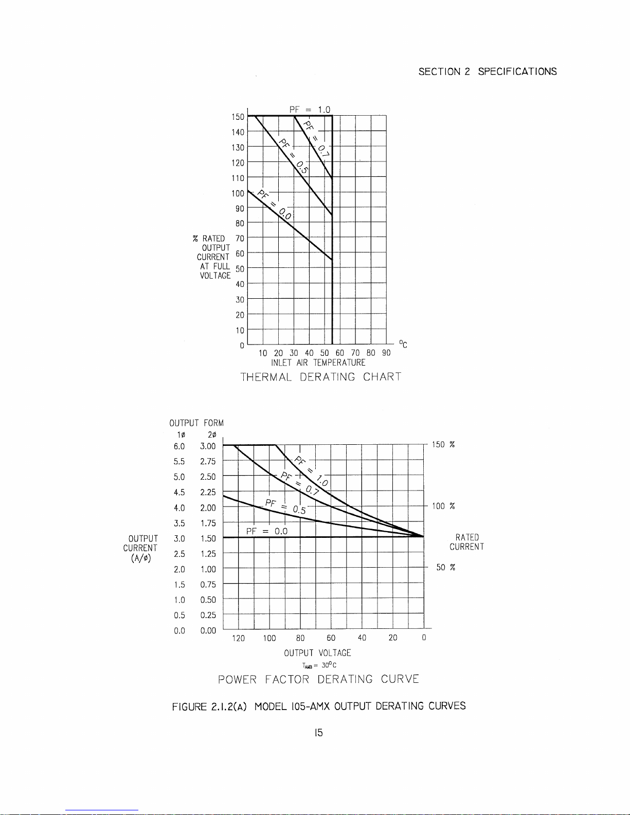
FIGURE 2.1.2(A) MODEL 105-AMX OUTPUT DERATING CURVES ....................................................15
FIGURE 2.1.2(B) MODEL 108-AMX OUTPUT DERATING CURVES ....................................................16
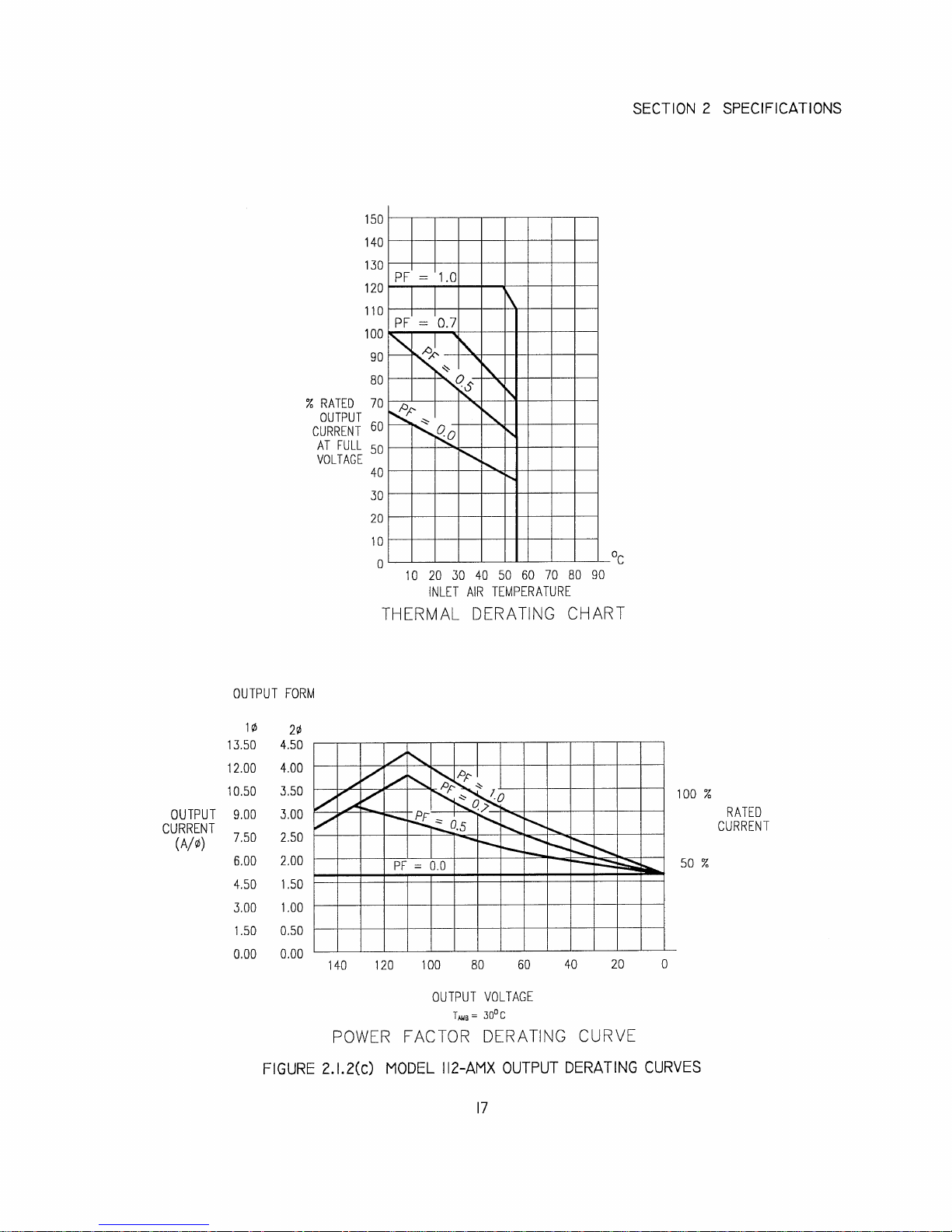
FIGURE 2.1.2(C) MODEL 112-AMX OUTPUT DERATING CURVES ....................................................17
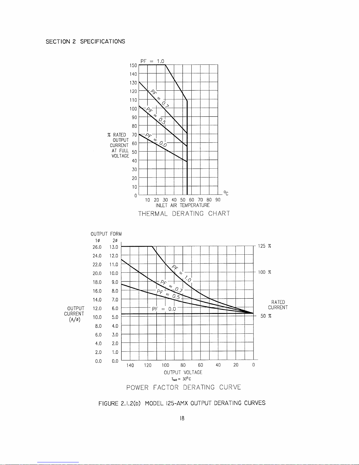
FIGURE 2.1.2(D) MODEL 125-AMX OUTPUT DERATING CURVES ....................................................18
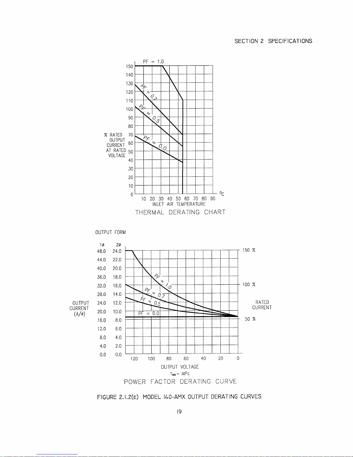
FIGURE 2.1.2(E) MODEL 140-AMX OUTPUT DERATING CURVES ....................................................19
FIGURE 2.1.2(E2) MODEL 160-AMX OUTPUT DERATING CURVES ................................................. 19A
FIGURE 2.1.2(F) MODEL 305-AMX OUTPUT DERATING CURVES ....................................................20
FIGURE 2.1.2(G) MODEL 308-AMX OUTPUT DERATING CURVES ....................................................21
FIGURE 2.1.2(H) MODEL 312-AMX OUTPUT DERATING CURVES ....................................................22
FIGURE 2.1.2(J) MODEL 320-AMX OUTPUT DERATING CURVES ....................................................23
FIGURE 2.1.2(K) MODEL 345-AMX OUTPUT DERATING CURVES ....................................................24
FIGURE 2.1.2(L) MODEL 360-AMX OUTPUT DERATING CURVES ....................................................25
FIGURE 2.1.2(M) MODEL 390-AMX OUTPUT DERATING CURVES ....................................................26
FIGURE 2.1.2(N) MODEL 3120-AMX OUTPUT DERATING CURVES ..................................................27
FIGURE 2.2.1 OUTLINE DRAWING, MODELS 105, 108, 112, 305, 308, & 312-AMX .....................34
FIGURE 2.2.2 OUTLINE DRAWING, MODEL 320-AMX ...................................................................35
FIGURE 2.2.3 OUTLINE DRAWING, MODELS 125, 140, 160, 345, & 360-AMX .............................36
FIGURE 2.2.4 OUTLINE DRAWING, MODELS 390, 3120-AMX, & MAGNETICS MODULE ........37
FIGURE 3.2.1 MODELS 105 & 108-AMX OUTPUT VOLTAGE CONFIGURATION........................42
FIGURE 3.2.2(A) MODEL 112-AMX OUTPUT VOLTAGE CONFIGURATION TABLE .......................44
FIGURE 3.2.2(B) MODEL 112-AMX OUTPUT VOLT. RANGE JUMPER (E1) LOCATION ................. 45
FIGURE 3.2.4 MODELS 105 & 108-AMX OUTPUT VOLTAGE CONFIGURATION........................48
FIGURE 3.2.5(A) MODEL 312-AMX OUTPUT VOLTAGE CONFIGURATION TABLE .......................49
FIGURE 3.2.5(B) MODEL 312-AMX OUTPUT VOLT. RANGE JUMPER (E1) LOCATION ................. 50
FIGURE 3.2.7 MODELS 140, 160, 345, 360, 390, & 3120-AMX OUTPUT VOLTAGE
CONFIGURATION..........................................................................................................54
FIGURE 3.3.1 MODELS 105, 108, 305, 308-AMX INPUT VOLTAGE CONFIGURATION ............... 56
FIGURE 3.3.4 MODELS 112 & 312-AMX INPUT VOLTAGE CONFIGURATION............................ 58
FIGURE 3.3.5 MODEL 320-AMX INPUT VOLTAGE CONFIGURATION ......................................... 60
FIGURE 3.3.6 MODEL 125-AMX INPUT VOLTAGE CONFIGURATION ......................................... 62
FIGURE 3.3.7 MODELS 140, 160, 345, 360, 390, 3120-AMX INPUT VOLTAGE
CONFIGURATION..........................................................................................................64
FIGURE 3.3.8 AMX-SERIES INPUT WIRING DIAGRAM ..................................................................66
FIGURE 3.4.1.1 SINGLE PHASE OUTPUT CONNECTION ...................................................................68
FIGURE 3.4.1.2 SINGLE PHASE OUTPUT CONNECTION ...................................................................69
FIGURE 3.4.2.1 SPLIT PHASE OUTPUT CONNECTION ....................................................................... 72
FIGURE 3.4.2.2 SPLIT PHASE OUTPUT CONNECTION ....................................................................... 73
FIGURE 3.4.3.1 THREE PHASE OUTPUT CONNECTION.....................................................................76
FIGURE 3.4.3.2 THREE PHASE OUTPUT CONNECTION.....................................................................77
FIGURE 3.4.5 MODELS 390 AND 3120-AMX CHASSIS INTERCONNECTIONS ............................80
FIGURE 3.8.1 EXTERNAL SENSE CONNECTION, MODELS 125, 140, 160, 345, 360, 390, &
3120-AMX........................................................................................................................ 84
FIGURE 3.8.2 EXTERNAL SENSE CONNECTION, MODELS 105, 108, 305, 308, 112, 312, &
320-AMX..........................................................................................................................85
FIGURE 4.1 FRONT PANEL CONTROLS..........................................................................................88
FIGURE 4.6.1 AMX-SERIES SYSTEM ARCHITECTURE...................................................................96
FIGURE 8.3.2 UMC-31 CONFIGURATION JUMPER LOCATIONS................................................. 120
FIGURE 8.4.1 UMC-31 FRONT PANEL CONTROLS ........................................................................124
FIGURE 8.4.2 UMC-31 J5 AUX I/O CONNECTOR ............................................................................126
FIGURE 8.5 UMC-31 CALIBRATION ADJUSTMENT LOCATIONS............................................ 128
-
iv-
PAGE

SECTION 1 GENERAL
SECTION 1
GENERAL
1.0 GENERAL
This manual is written to provide the information required to use the AMX-Series AC Power Source. Operation
of the Models 105-AMX, 108-AMX, 112-AMX, 125-AMX, 140-AMX, 160-AMX, 305-AMX, 308-AMX, 312AMX, 320-AMX, 345-AMX, 360-AMX, 390-AMX, and 3120-AMX is described in this document.
This manual is an Operations Manual. Installation, operation, and calibration are the subjects covered by this
manual.
1.1 USING THIS MANUAL
This manual provides instructions for installation and use of the AMX-Series Power Source equipment. For this
reason, it is very important that the user reads sections 1, 3, and 4 prior to using this equipment. A thorough
understanding of these sections is required to properly operate this equipment.
Section 2 states the specifications of the equipment. Knowledge of this information is required to gain
maximum use of this equipment for a given application. The user is encouraged to read this section in order to
gain a deeper understanding of the capabilities of the AMX-Series Power Source.
Sections 5 and 6 list maintenance and calibration requirements of this equipment. Refer to these sections when
either maintenance or calibration is required.
Section 7 describes service methodology and provides system, sub-assembly, and component part numbers to
aid the user in making factory authorized field repairs.
This equipment is configured with a modular controller. This allows for the creation of systems with various
control characteristics and specifications. This manual describes the operation of the basic power source.
Detailed information relative to the UMC-31 Controller is also included is described in Section 8 of this
manual. The UPC controllers are described in a separate manual. Refer to the UPC-Series Operation Manual
for such information.
Section 9 contains product change notices, errata and data relative to customer specified modifications.
Always read this section before operating the equipment. This is especially true when modifications have been
installed, since these can change system operation.
If questions arise while reading this manual, the user is encouraged to call the Pacific Power Source. Pacific
maintains a toll-free number which is 1-800-854-2433.
- 1 -

SECTION 1 GENERAL
MODEL 305−AMX
w/ UMC−31 Controller
MODEL 360−AMX
w/ UPC−32 Controller
4
FIGURE 1.3

SECTION 1 GENERAL
1.3 GENERAL PRODUCT DESCRIPTION
The AMX-Series Power Source is high-performance AC power conversion equipment. This series of
equipment features models with power ratings from 500 VA to 12 kVA. All systems are designed to fit into the
standard 19 inch rack. These systems are suitable for use as frequency changers as well as sophisticated test
power generators.
All systems are configured with an interchangeable controller. Controller options range from the basic manual
type (UMC-Series) to the sophisticated programmable controller (UPC-Series). The manual controller allows
the user to adjust voltage and frequency. The programmable controller, on the other hand, not only allows
control of voltage and frequency, but also allows the user to simulate virtually any transient (including subcycle waveform disturbance) required for testing today's modern electronic equipment.
The standard output voltage range of the AMX-Series is 0-135 VAC
(0-150 VAC
l-n
Additionally, the Models 112-AMX and 312-AMX can be configured for several output voltage ranges
between and including 0-110 VAC
and 0-150 VAC
l-n
. Optional output transformers are available to provide
l-n
higher voltages. Voltage ratios up to 2.5:1 are available.
The AMX-Series consists of the basic models listed below:
1. Model 105-AMX - 500 VA Chassis capable of 1 or 2 Phase operation. Standard
Output voltage range is 0-135 VAC
, 1φ or 0-270 VAC, 2 Phase. Phase separation fixed at 180°
l-n
when operating in 2 Phase Mode.
2. Model 108-AMX - Same as 105-AMX, but rated for 750 VA output power.
3. Model 112-AMX - Same as 105-AMX, but rated for 1.2 kVA output power. Standard
Output voltage ranges are 0-110 VAC
through 0-150 VAC
l-n
, 1φ or 0-220 VAC through 0-300 VAC,
l-n
2 Phase.
4. Model 125-AMX - Same as 105-AMX, but rated for 2.5 kVA output power. Standard
Output voltage range is 0-150 VAC
, 1φ or 0-300 VAC, 2 Phase.
l-n
5. Model 140-AMX - Same as 105-AMX, but rated for 4.0 kVA output power.
6. Model 160-AMX - Same as 105-AMX, but rated for 6.0 kVA output power.
7. Model 305-AMX - 500 VA Chassis capable of 1, 2, or 3 Phase operation. Standard
Output voltage range is 0-135 VAC
. Phase separation fixed at 180° when operating in 2 Phase
l-n
Mode. In 3 Phase Mode, phase separation is fixed at 120° or programmable.
8. Model 308-AMX - Same as 305-AMX, but rated for 750 VA output power.
9. Model 312-AMX - Same as 305-AMX, but rated for 1.2 kVA output power. Standard
Output voltage ranges are 0-110 VAC
through 0-150 VAC
l-n
, 1φ or 0-220 VAC through 0-300 VAC,
l-n
2 Phase.
10. Model 320-AMX - Same as 305-AMX, but rated for 2.25 kVA output power.
for the Model 125-AMX).
l-n
5

SECTION 1 GENERAL
1.3 GENERAL PRODUCT DESCRIPTION (cont.)
11. Model 345-AMX - Same as 305-AMX, but rated for 4.5 kVA output power.
12. Model 360-AMX - Same as 305-AMX, but rated for 6.0 kVA output power.
13. Model 390-AMX - Same as 305-AMX, but rated for 9.0 kVA output power.
14. Model 3120-AMX - Same as 305-AMX, but rated for 12.0 kVA output power.
External voltage sense is provided on all systems. Systems configured with the programmable controller also
feature Continuous Self Calibration (CSC).
Output voltage and current metering is provided on all systems. Specifications of the metering functions vary
by controller type. Refer to Section 8 or the UPC-Series Operation Manual, as appropriate, for details relative
to the metering functions.
6

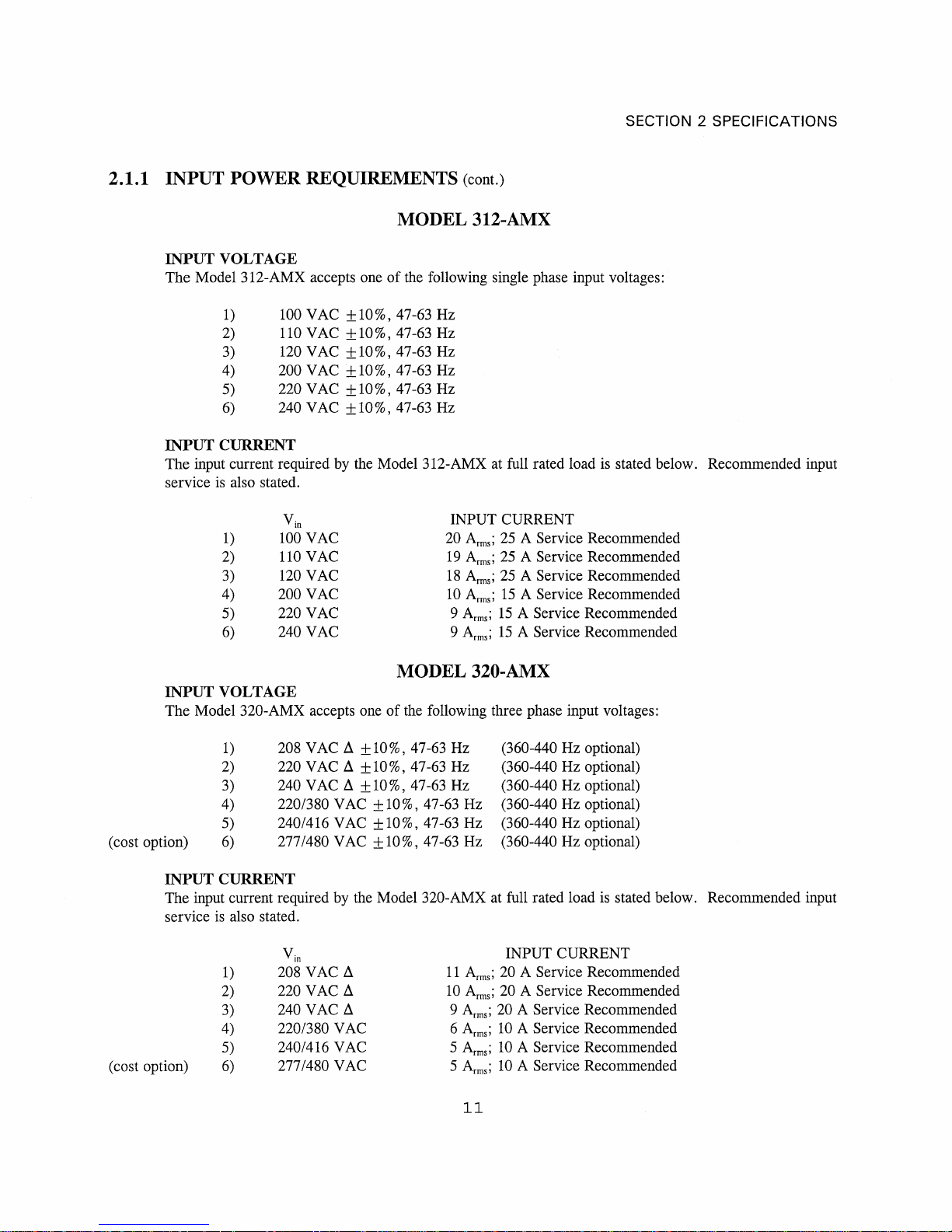
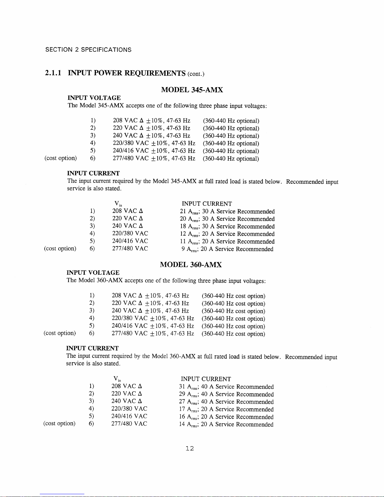
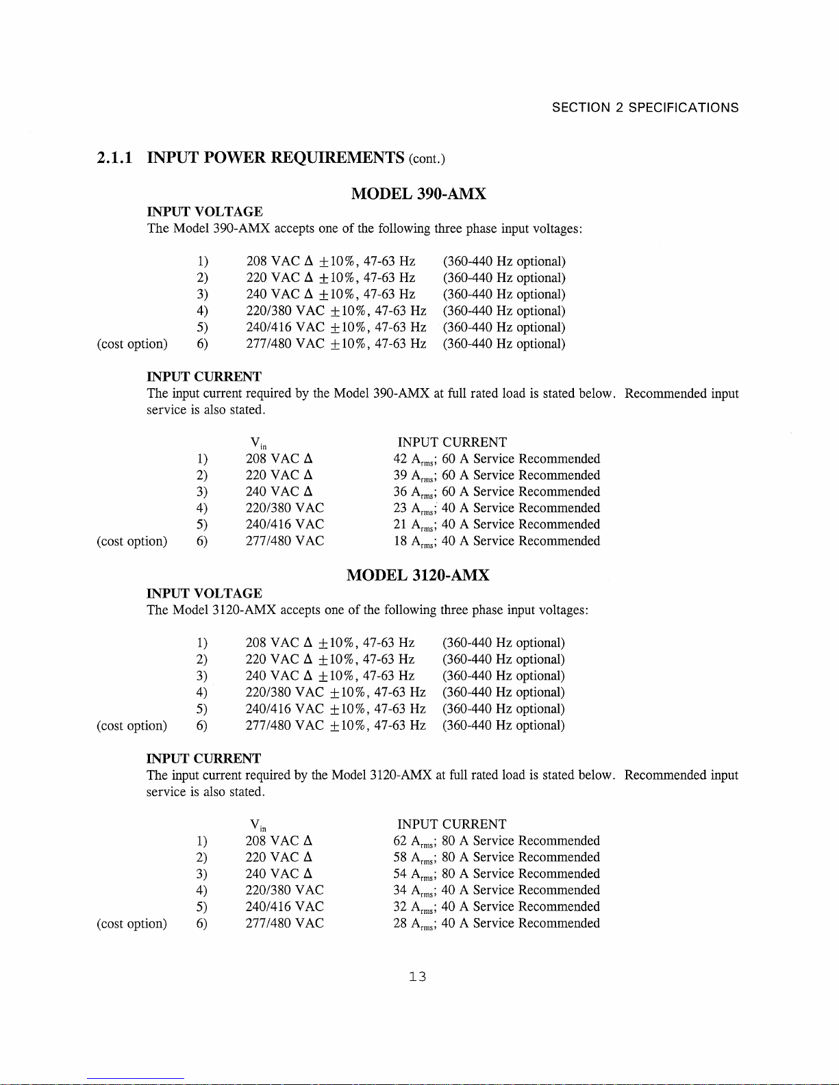
SECTION 2 SPECIFICATIONS
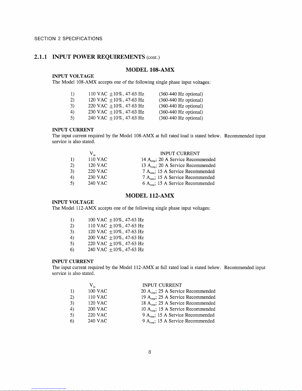
2.1.1 INPUT POWER REQUIREMENTS (cont.)
MODEL 125-AMX
INPUT VOLTAGE
The Model 125-AMX accepts one of the following three phase input voltages:
1) 208 VAC ∆ ±10%, 47-63 Hz (360-440 Hz optional)
2) 220 VAC ∆ ±10%, 47-63 Hz (360-440 Hz optional)
3) 240 VAC ∆ ±10%, 47-63 Hz (360-440 Hz optional)
4) 220/380 VAC ±10%, 47-63 Hz (360-440 Hz optional)
5) 240/416 VAC ±10%, 47-63 Hz (360-440 Hz optional)
(cost option) 6) 277/480 VAC ±10%, 47-63 Hz (360-440 Hz optional)
INPUT CURRENT
The input current required by the Model 125-AMX at full rated load is stated below. Recommended input
service is also stated.
INPUT CURRENT
V
1) 208 VAC ∆ 12 A
in
2) 220 VAC ∆ 11 A
3) 240 VAC ∆ 10 A
4) 220/380 VAC 6 A
5) 240/416 VAC 6 A
(cost option) 6) 277/480 VAC 5 A
; 20 A Service Recommended
rms
; 20 A Service Recommended
rms
; 20 A Service Recommended
rms
; 10 A Service Recommended
rms
; 10 A Service Recommended
rms
; 10 A Service Recommended
rms
MODEL 140-AMX
INPUT VOLTAGE
The Model 140-AMX accepts one of the following three phase input voltages:
1) 208 VAC ∆ ±10%, 47-63 Hz (360-440 Hz cost option)
2) 220 VAC ∆ ±10%, 47-63 Hz (360-440 Hz cost option)
3) 240 VAC ∆ ±10%, 47-63 Hz (360-440 Hz cost option)
4) 220/380 VAC ±10%, 47-63 Hz (360-440 Hz cost option)
5) 240/416 VAC ±10%, 47-63 Hz (360-440 Hz cost option)
(cost option) 6) 277/480 VAC ±10%, 47-63 Hz (360-440 Hz cost option)
INPUT CURRENT
The input current required by the Model 140-AMX at full rated load is stated below. Recommended input
service is also stated.
INPUT CURRENT
V
1) 208 VAC ∆ 21 A
in
2) 220 VAC ∆ 19 A
3) 240 VAC ∆ 18 A
4) 220/380 VAC 12 A
5) 240/416 VAC 11 A
(cost option) 6) 277/480 VAC 9 A
; 30 A Service Recommended
rms
; 30 A Service Recommended
rms
; 30 A Service Recommended
rms
; 20 A Service Recommended
rms
; 20 A Service Recommended
rms
; 20 A Service Recommended
rms
9

SECTION 2 SPECIFICATIONS
2.1.1 INPUT POWER REQUIREMENTS (cont.)
MODEL 160-AMX
INPUT VOLTAGE
The Model 160-AMX accepts one of the following three phase input voltages:
1) 208 VAC ∆ ±10%, 47-63 Hz (360-440 Hz cost option)
2) 220 VAC ∆ ±10%, 47-63 Hz (360-440 Hz cost option)
3) 240 VAC ∆ ±10%, 47-63 Hz (360-440 Hz cost option)
4) 220/380 VAC ±10%, 47-63 Hz (360-440 Hz cost option)
5) 240/416 VAC ±10%, 47-63 Hz (360-440 Hz cost option)
(cost option) 6) 277/480 VAC ±10%, 47-63 Hz (360-440 Hz cost option)
INPUT CURRENT
The input current required by the Model 360-AMX at full rated load is stated below. Recommended input
service is also stated.
INPUT CURRENT
V
1) 208 VAC ∆ 31 A
in
2) 220 VAC ∆ 29 A
3) 240 VAC ∆ 27 A
4) 220/380 VAC 17 A
5) 240/416 VAC 16 A
(cost option) 6) 277/480 VAC 14 A
; 40 A Service Recommended
rms
; 40 A Service Recommended
rms
; 40 A Service Recommended
rms
; 20 A Service Recommended
rms
; 20 A Service Recommended
rms
; 20 A Service Recommended
rms
9A

SECTION 2 SPECIFICATIONS
(THIS PAGE INTENTIONALLY BLANK)
9B

SECTION 2 SPECIFICATIONS
INPUT VOLTAGE
The Model 305-AMX accepts one of the following single phase input voltages:
1) 110 VAC ±10%, 47-63 Hz (360-440 Hz optional)
2) 120 VAC ±10%, 47-63 Hz (360-440 Hz optional)
3) 220 VAC ±10%, 47-63 Hz (360-440 Hz optional)
4) 230 VAC ±10%, 47-63 Hz (360-440 Hz optional)
5) 240 VAC ±10%, 47-63 Hz (360-440 Hz optional)
INPUT CURRENT
The input current required by the Model 305-AMX at full rated load is stated below. Recommended input
service is also stated.
INPUT CURRENT
V
in
1) 110 VAC 9 A
2) 120 VAC 8 A
3) 220 VAC 5 A
4) 230 VAC 4 A
5) 240 VAC 4 A
INPUT VOLTAGE
The Model 308-AMX accepts one of the following single phase input voltages:
1) 110 VAC ±10%, 47-63 Hz (360-440 Hz optional)
2) 120 VAC ±10%, 47-63 Hz (360-440 Hz optional)
3) 220 VAC ±10%, 47-63 Hz (360-440 Hz optional)
4) 230 VAC ±10%, 47-63 Hz (360-440 Hz optional)
5) 240 VAC ±10%, 47-63 Hz (360-440 Hz optional)
INPUT CURRENT
The input current required by the Model 308-AMX at full rated load is stated below. Recommended input
service is also stated.
INPUT CURRENT
V
in
1) 110 VAC 14 A
2) 120 VAC 13 A
3) 220 VAC 7 A
4) 230 VAC 7 A
5) 240 VAC 6 A
MODEL 305-AMX
; 20 A Service Recommended
rms
; 20 A Service Recommended
rms
; 15 A Service Recommended
rms
; 15 A Service Recommended
rms
; 15 A Service Recommended
rms
MODEL 308-AMX
; 20 A Service Recommended
rms
; 20 A Service Recommended
rms
; 15 A Service Recommended
rms
; 15 A Service Recommended
rms
; 15 A Service Recommended
rms
10

SECTION 2 SPECIFICATIONS
2.1.2 OUTPUT POWER
OUTPUT VOLTAGE RANGE
DIRECT-COUPLED
The standard output voltage range of the AMX-Series Power Source is 0-135 VAC
Model 125-AMX) when operated in the direct-coupled mode. Additionally, the Models 112-AMX and 312AMX can be configured for several direct-coupled output voltage ranges between and including 0-110 VAC
and 0-150 VAC
TRANSFORMER-COUPLED
The output voltage range of the AMX-Series Power Source varies when operated in the transformer-coupled
mode. Maximum output voltage is determined by the transformer turns ratio. See list below for maximum
output voltage vs. turns ratio.
TURNS RATIO MAXIMUM OUTPUT VOLTAGE (No Load)
1.5:1 204 VAC
2.0:1 273 VAC
2.5:1 341 VAC
OUTPUT CURRENT
FULL-RATED CURRENT
The full-rated output current the AMX-Series Power Source is listed below by model number. Current stated
for output voltage set to 125 VAC
maximum current at reduced voltage. Output current ratings are scaled appropriately when using transformercoupled outputs.
MODEL I
105-AMX 4 A 40 A 2 A 20 A N/A N/A
108-AMX 6 A 40 A 3 A 20 A N/A N/A
112-AMX 10 A 40 A 5 A 20 A N/A N/A
125-AMX 20 A 90 A 10 A 45 A N/A N/A
140-AMX 32 A 140 A 16 A 70 A N/A N/A
160-AMX 48 A 210 A 16 A 70 A N/A N/A
305-AMX 4 A 45 A 2 A 15 A 1.33 A 15 A
308-AMX 6 A 45 A 2 A 15 A 2 A 15 A
312-AMX 10 A 45 A 3 A 15 A 3 A 15 A
320-AMX 18 A 60 A 6 A 20 A 6 A 20 A
345-AMX 36 A 165 A 12 A 55 A 12 A 55 A
360-AMX 48 A 210 A 16 A 70 A 16 A 70 A
390-AMX 72 A 330 A 24 A 110 A 24 A 110 A
3120-AMX 96 A 410 A 32 A 140 A 32 A 140 A
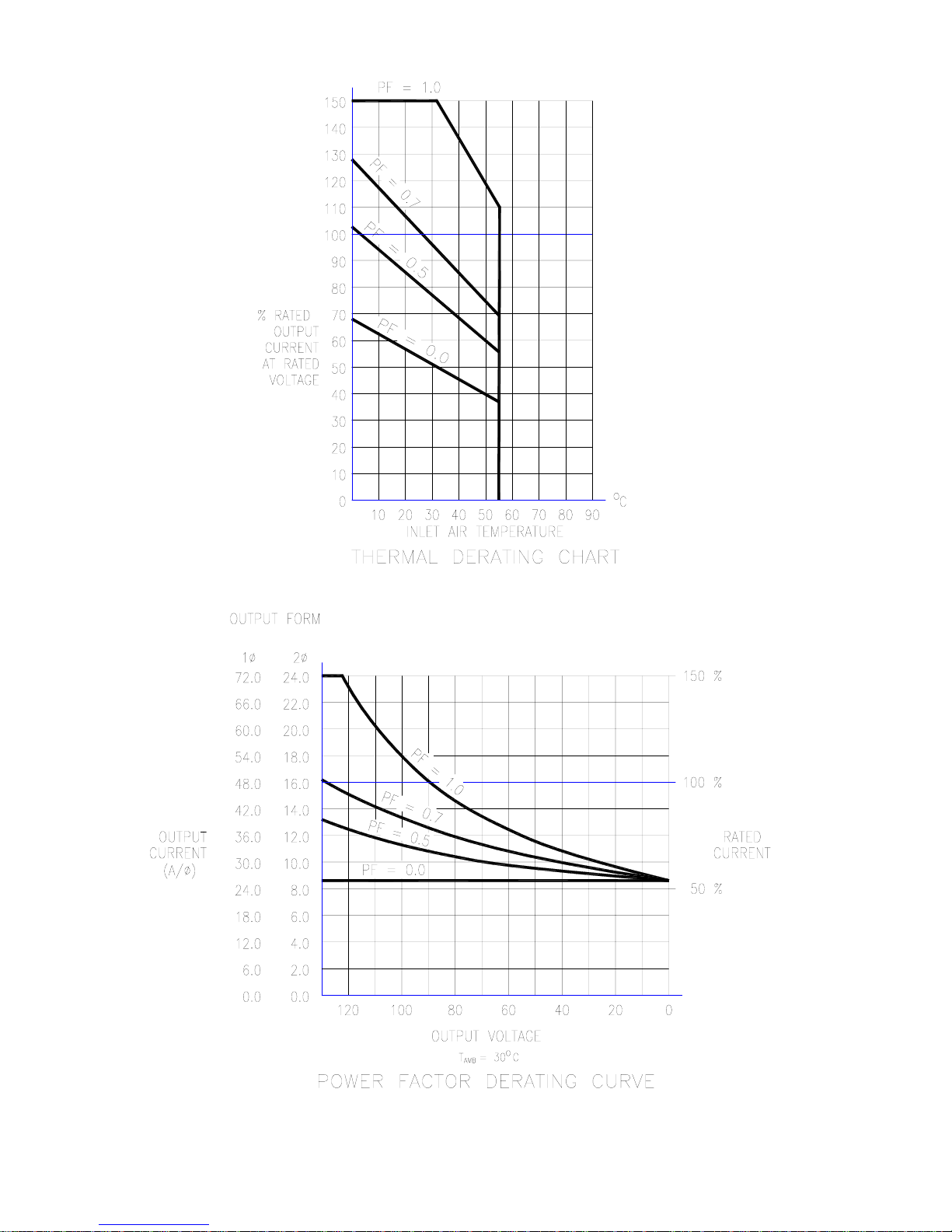
OVERLOAD OPERATION
The AMX-Series Power Source will deliver up to 150% of rated rms output current into unity power factor
loads at full-rated output voltage. Low output power factor, reduced output voltage, and elevated ambient
temperatures will increase the internal dissipation of the power source and can cause overload shutdown due to
over-temperature conditions. Length of time to reach over-temperature varies with the models and the above
parameters.
. These voltages are stated for full rated load and nominal input voltage applied.
l-n
1φ 2φ 3φ
out, rms
I
I
out, pk
(0-150 VAC
l-n
l-n
l-n
l-n
. Refer to the Power Factor Derating chart of Figure 2.1.2(A-N) for
l-n
out, rms
I
I
out, pk
out, rms
I
out, pk
for the
l-n
l-n
14

SECTION 2 SPECIFICATIONS
FIGURE 2.1.2(E2) MODEL 160-AMX OUTPUT DERATING CURVES
19A
 Loading...