

Pacific 110ACX, 118ACX, 115ACX Operation Manual

ACX SERIES
AC POWER SOURCES
OPERATION
MANUAL

PAGE LEFT INTENTIONALLY BLANK FOR HARDCOPY VERSIONS OF THIS DOCUMENT

THIS MANUAL ASSIGNED TO S/N :
ACX-SERIES
OPERATION MANUAL
FOR THE
MODELS
110ACX
115ACX
118ACX
PPS PART NO. 150118-10
THE INFORMATION CONTAINED
IN THIS MANUAL IS PROPRIETARY TO
PACIFIC POWER SOURCE, INC.
AND MAY NOT BE COPIED OR REPRINTED
WITHOUT ITS EXPRESSED WRITTEN CONSENT.
PACIFIC POWER SOURCE, INC.
17692 Fitch Irvine, CA 92614
SIXTH EDITION
COPYRIGHT ©, PPS, JUNE 2014

CERTIFICATION
PACIFIC POWER SOURCE CERTIFIES THAT THIS INSTRUMENT WAS
THOROUGHLY TESTED AND INSPECTED AND FOUND TO MEET OR
EXCEED ITS PUBLISHED SPECIFICATIONS WHEN IT WAS SHIPPED
FROM THE FACTORY.
LIMITED WARRANTY
Pacific Power Source (PPS) warrants each unit to be free from defects in
material and workmanship. For the period of two (2) years from the date of
shipment to the purchaser, PPS will either repair or replace, at its sole
discretion, any unit returned to its factory in Irvine, California or other factory
authorized service center. This warranty does not cover batteries. It does not
cover damage arising from misuse of the unit or attempted field modifications or
repairs. This warranty specifically excludes damage to other equipment
connected to this unit.
Upon notice from the purchaser within (30) days of shipment of units found to be
defective in material or workmanship, PPS will pay all shipping charges for the
repair or replacement. If notice is received more than thirty (30) days from
shipment, all shipping charges shall be paid by the purchaser. Units returned
on debit memos will not be accepted and will be returned without repair.
This warranty is exclusive of all other warranties, express or implied.
For a listing of local contacts or other information, please visit us online at:
www.pacificpower.com .

TABLE OF CONTENTS
PAGE
GENERAL ................................................................................................................................................... 7
1
1.1 USING THIS MANUAL ..................................................................................................................... 7
1.2 SAFETY NOTICES .......................................................................................................................... 8
1.3 GENERAL PRODUCT DESCRIPTION .......................................................................................... 12
2 SPECIFICATIONS .................................................................................................................................... 13
2.1 ELECTRICAL SPECIFICATIONS .................................................................................................. 13
2.1.1 INPUT POWER REQUIREMENTS ..................................................................................................... 13
2.1.2 OUTPUT POWER ............................................................................................................................... 14
2.1.3 OUTPUT POWER FACTOR ............................................................................................................... 16
2.1.4 OUTPUT FREQUENCY ...................................................................................................................... 16
2.1.5 OUTPUT DISTORTION ...................................................................................................................... 16
2.1.6 OUTPUT LOAD REGULATION .......................................................................................................... 16
2.1.7 INPUT LINE REGULATION ................................................................................................................ 16
2.1.8 OUTPUT BANDWIDTH ....................................................................................................................... 16
2.1.9 LOAD TRANSIENT RESPONSE ........................................................................................................ 16
2.1.10 OUTPUT DC OFFSET ........................................................................................................................ 17
2.1.11 OUTPUT PROTECTION ..................................................................................................................... 17
2.1.12 OUTPUT CONTROL CHARACTERISTICS ........................................................................................ 17
2.1.13 OUTPUT ISOLATION ......................................................................................................................... 17
2.2 MECHANICAL SPECIFICATIONS ................................................................................................. 17
2.2.1 DIMENSIONS AND WEIGHT.............................................................................................................. 17
2.2.1 DIMENSIONS DRAWINGS ................................................................................................................. 18
2.2.2 INPUT POWER CONNECTION .......................................................................................................... 19
2.2.3 OUTPUT POWER CONNECTION ...................................................................................................... 19
2.2.4 CHASSIS SLIDE MOUNTS ................................................................................................................ 19
2.3 ENVIRONMENTAL SPECIFICATIONS ......................................................................................... 19
2.3.1 TEMPERATURE RANGE ................................................................................................................... 19
2.3.2 COOLING ........................................................................................................................................... 19
2.3.3 ALTITUDE ........................................................................................................................................... 19
2.3.4 POLLUTION DEGREE ........................................................................................................................ 19
2.3.5 THERMAL PROTECTION .................................................................................................................. 19
3 INSTALLATION ........................................................................................................................................ 20
3.1 CHASSIS PLACEMENT................................................................................................................. 20
3.1 CHASSIS PLACEMENT (CONTINUED) ............................................................................................ 21
3.2 OUTPUT RANGE CONFIGURATION ............................................................................................ 21
3.3 INPUT POWER CONNECTION ..................................................................................................... 22
3.3 INPUT POWER CONNECTION (CONTINUED) ................................................................................ 23
3.4 OUTPUT POWER CONNECTION ................................................................................................. 24
3.4 OUTPUT POWER CONNECTION (CONTINUED) ............................................................................ 25
3.5 REMOTE INTERFACE ................................................................................................................... 25
3.6 AUX I/O INSTALLATION ................................................................................................................ 26
3.7 EXTERNAL SENSE CONNECTION .............................................................................................. 27
5

TABLE OF CONTENTS
PAGE
OPERATION ............................................................................................................................................. 28
4
4.1 FRONT PANEL CONTROLS ......................................................................................................... 28
4.2 INITIAL POWER-UP ...................................................................................................................... 29
4.3 ROUTINE POWER-UP .................................................................................................................. 30
4.4 SYSTEM TURN-OFF ..................................................................................................................... 30
4.5 SYSTEM SHUTDOWN .................................................................................................................. 31
4.5.1 SHUTDOWN CONDITIONS ...................................................................................................................... 31
4.5.2 RESETT ING SHU TDOWN FAULTS ......................................................................................................... 31
4.6 OUTPUT VOLTAGE FORMS ......................................................................................................... 32
4.7 AUDIBLE ALERT ........................................................................................................................... 32
4.8 CONSTANT CURRENT MODE ..................................................................................................... 33
4.9 CONSTANT VOLTAGE MODE (CURRENT PROTECTION MODE) ............................................. 34
4.10 POWER PROTECTION MODE ..................................................................................................... 36
5 MAINTENANCE ........................................................................................................................................ 37
5.1 MAINTENANCE INTERVAL........................................................................................................... 37
6 CALIBRATION .......................................................................................................................................... 38
6.1 CALIBRATION INTERVAL ............................................................................................................. 38
6.2 TEST EQUIPMENT REQUIREMENTS .......................................................................................... 38
6.3 CALIBRATION PROCEDURE ....................................................................................................... 38
6.3 CALIBRATION PROCEDURE ( CONT. ) ......................................................................................... 39
6.3.1 CONTROLLER CALIBRATION ........................................................................................................... 40
6.3.2 POWER SOURCE LOAD TEST ......................................................................................................... 40
7 SERVICE ................................................................................................................................................... 41
7.1 SERVICE PROCEDURE................................................................................................................ 41
7.2 SYSTEM LEVEL FACTORY PART NUMBERS ............................................................................. 41
7.3 SUB-ASSEMBLY AND CHASSIS COMPONENT PART NUMBERS ............................................ 41
INDEX ................................................................................................................................................................. 42
9 MODIFICATIONS AND CHANGE NOTICES .......................................................................................... 43
LIST OF ILLUSTRATIONS
FIGURE 1.3 ACX SERIES POWER SOURCE FRONT VIEW...……………….……..…….……………….6
FIGURE 2.1 INPUT CURRENT VS. OUTPUT POWER FOR MODEL 118ACX…………..……………....7
FIGURE 2.2 OUTPUT RATING CURVES BY MODEL…………………………………………………….....9
FIGURE 2.3 OUTLINE DRAWING ....…………………………….…………………...................................12
FIGURE 3.3 INPUT AND OUTPUT CONNECTIONS …………….…………………………………….……17
FIGURE 3.4 ACX-SERIES SYSTEM ARCHITECTURE ………………………………………….………….19
FIGURE 3.5 AUX I/O DB25S PIN OUT DIAGRAM.……………………………………………….………….20
FIGURE 3.6 EXTERNAL SENSE WIRING ……………………………………………………………………21
FIGURE 4.1 FRONT PANEL CONTROLS …………………………………………………………………….22
6

Model
Maximum Output Power VA
110ACX
1000 VA
115ACX
1500 VA
118ACX
1800 VA
1 GENERAL
This manual provides information required to properly use one of the ACX Series AC Power
Source models. This is a general Operations Manual and it describes the operation of the basic
power source. Installation, operation, and calibration are the subjects covered.
At this time, there are three models available in the ACX Series:
All ACX models are configured with a digital UPC (Universal Programmable Controller).
Detailed operating instruction and control and metering specifications are described in the UPC
Series Operation Manual which is supplied with the unit.
SECTION 1 GENERAL
SECTION 1
GENERAL
1.1 USING THIS MANUAL
This manual provides instructions for installation and use of the ACX Series Power Source
equipment. For this reason, it is very important that the user reads sections 1 GENERAL
information, 3 INSTALLATION, and 4 OPERATION, prior to using this equipment. A thorough
understanding of these sections is required to safely and properly operate this equipment.
Section 2 lists the specifications of the equipment. Knowledge of this information is required to
gain maximum use of this equipment for a given application. The user is encouraged to read
this section in order to gain a deeper understanding of the capabilities of the ACX Power
Source.
Sections 5 and 6 list MAINTENANCE and CALIBRATION requirements of this equipment.
Refer to these sections when either maintenance or calibration is required.
Section 7 describes SERVICE methodology and provides system, sub-assembly, and
component part numbers to aid the operator in making any factory authorized field repairs.
Section 8 contains the INDEX for this manual.
Section 9 contains product change notices, errata, and data relative to customer specified
modifications. Read Section 9 before operating the equipment. This is especially true when
modifications (MODs) have been installed, since these can change system operation.
If questions arise while reading this manual, the user is encouraged to call the Pacific Power
Source customer service department. Pacific maintains a toll-free number: 1-800-854-2433 or
use +1 (949) 251-1800.
7

SECTION 1 GENERAL
1.2 SAFETY NOTICES
The ACX is capable of transferring very large amounts of electrical energy very quickly. This
basic quality is fundamental to any high-performance power source. The warnings and cautions
listed below should be observed at all times.
WARNINGS are conditions which are hazardous to user personnel. All warnings throughout
this manual will be formatted as shown below. A condition which is hazardous to both personnel
and equipment will be issued as a warning.
CAUTION statements indicate a dangerous situation which may damage the equipment but is
not a threat to life or limb. Cautions will assume the format shown on page 3. All cautions
should be rigorously observed.
CONSIGNES de SECURITÉ
La ACX est en mesure de transférer des forts niveaux d’énergie électrique et cela de manière
très rapide. Cette caractéristique est une qualité fondamentale pour ce type d’équipement haute
performance. Les règles de sécurité, avertissements et précautions décris ci-dessous doivent
être observés à tout moment.
Attention! (Avertissements): conditions dangereuses pour le personnel utilisateur. Tout les
avertissements dans ce manuel seront formattés et indiqués comme ci-dessous. Toute
condition qui peut être dangereuse à la fois pour le personnel utilisateur et l’équipement sera
indiquée comme avertissement.
Précautions: elles indiquent une situation dangereuse pouvant endommager l’équipement,
mais qui n’est pas une menace pour la vie ou un danger pour un member. Les messages de
précautions seront formattés comme sur la page 3 tout au long ce manuel et doivent étre
observés rigoureusement.
8

SECTION 1 GENERAL
WARNING
ATTENTION
CIRCUIT PAR L’INTERMEDIAIRE DES BIJOUX QUI
MAINTENANCE
THIS EQUIPMENT CONTAINS HIGH ENERGY, LOW IMPEDANCE CIRCUITS!!
LETHAL POTENTIALS ARE CONTAINED WITHIN THE CABINET.
CARE MUST BE EXERCISED WHEN SERVICING THIS EQUIPMENT
TO PREVENT SERIOUS OPERATOR INJURY OR EQUIPMENT DAMAGE.
VOLTAGE AT THE TERMINALS RESPONDS INSTANTLY WHEN THE OUTPUT IS ACTIVATED.
OBSERVE THE FOLLOWING WHEN SERVICE, MAINTENANCE, OR CALIBRATION ARE REQUIRED:
1. REMOVE ALL JEWELRY FROM HANDS, ARMS AND NECK WHEN SERVICING THIS
EQUIPMENT. THIS PREVENTS THE POSSIBILITY OF SHORTING THROUGH THE JEWELRY
AND CAUSING BURNS OR ELECTROCUTION OF THE OPERATOR.
2. WEAR SAFETY GLASSES WHEN SERVICING THIS EQUIPMENT TO PREVENT EYE INJURY
DUE TO FLYING PARTICLES CAUSED BY ACCIDENTAL SHORT CIRCUIT CONDITIONS.
3. DO NOT REMOVE ANY PANEL OR COVER WITHOUT FIRST REMOVING THE INPUT SERVICE
BY OPENING ALL CIRCUIT BREAKERS.
4. SERVICE OTHER THAN EXTERNAL CLEANING SHOULD BE REFERRED TO PERSONNEL
AUTHORIZED BY THE FACTORY TO SERVICE THIS EQUIPMENT.
CET EQUIPEMENT CONTIENT DES CIRCUITS ELECTRIQUES DE FORTE ENERGIE ET A FAIBLE
IMPEDANCE!! DES POTENTIELS A CARACTERE MORTEL SONT CONTENUS A L’INTERIEUR DE
L’EQUIPEMENT.
UNE ATTENTION PARTICULIERE EST IMPERATIVE DANS LE CADRE DU SERVICE DE CET
EQUIPEMENT AFIN DE PREVENIR TOUT RISQUE POUVANT ENTRAINER UN ACCIDENT DE
L’OPERATEUR OU UN DOMMAGE DE L’EQUIPEMENT.
LA TENSION AUX BORNES DE SORTIE DE L’EQUIPEMENT EST PRESENTE INSTANTANEMENT
LORSQUE LA SORTIE EST ACTIVEE.
LES REGLES DE SECURITE SUIVANTES DOIVENT ETRE SUIVIES DANS LE CADRE DU SERVICE,
DE LA MAINTENANCE OU DE LA CALIBRATION DE L’EQUIPEMENT:
1. OTER TOUS LES BIJOUX DES MAINS, BRAS ET COU PENDANT LE SERVICE DE L’EQUIPEMENT
AFIN DE PREVENIR TOUT RISQUE DE COURTPOURRAIT CONDUIRE A DES BRULURES OU ELECTROCUTION DE L’OPERATEUR
2. PORTER DES LUNETTES A VERRE DE SECURITE PENDANT LE SERVICE DE L’EQUIPEMENT
AFIN DE PREVENIR TOUT RISQUE D’ACCIDENT OCULAIRE POUVANT PROVENIR DE
PARTICULES VOLANTES CREEES DANS DES CONDITIONS DE COURT-CIRCUIT
ACCIDENTELLES.
3. NE JAMAIS OTER OU RETIRER DES PANNEAUX OU COUVERCLES DE PROTECTION SANS
AVOIR AU PREALABLE COUPER LE CIRCUIT D’ALIMENTATION DE L’EQUIPEMENT.
4. TOUT AUTRE SERVICE QUE LE NETTOYAGE EXTERNE DE L’EQUIPEMENT NECESSITE
L’INTERVENTION DE PERSONNEL QUALIFIE ET AUTORISE PAR L’USINE POUR CETTE
9

SECTION 1 GENERAL
CAUTION
PRECAUTION
WARNING
ATTENTION
1.2 SAFETY NOTICES (continued)
IF THIS EQUIPMENT IS NOT USED IN A MANNER SPECIFIED BY THE MANUFACTURER,
THE PROTECTION PROVIDED BY THE EQUIPMENT MAY BE IMPAIRED
SI CET EQUIPEMENT N’EST PAS UTILISE D’UNE MANIERE SPECIFIEE PAR LE FABRICANT,
LA PROTECTION FOURNIE PAR L’EQUIPEMENT PEUT ETRE ALTEREE
READ SECTIONS 1, 3, AND 4 OF THIS MANUAL
BEFORE INSTALLING OR OPERATING THIS EQUIPMENT.
LIRE LES CHAPITRES 1,3 ET 4 DE CE MANUEL
AVANT L’INSTALLATION ET L’UTILISATION DE CET EQUIPEMENT
10
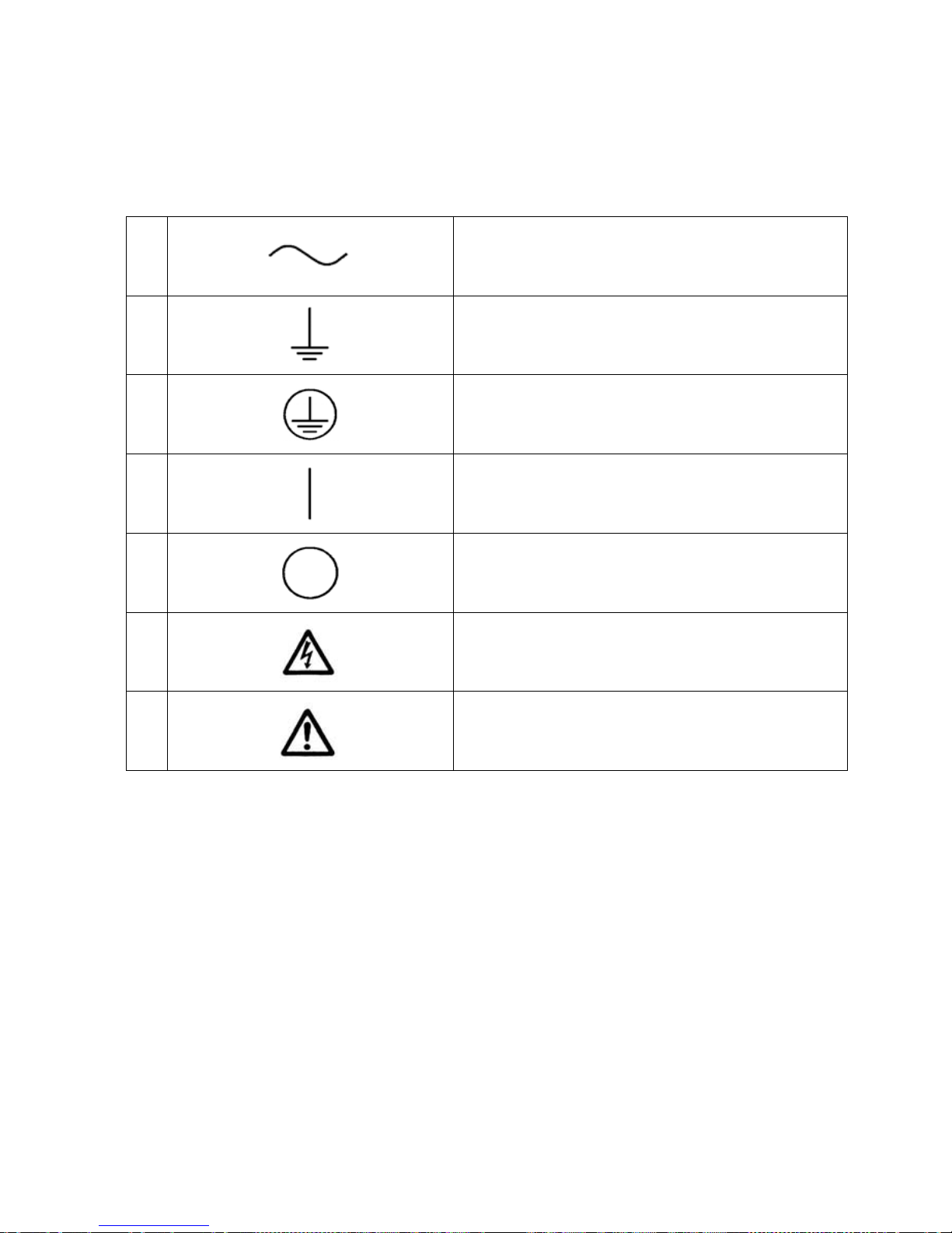
1.2 SAFETY NOTICES (continued)
SAFETY SYMBOLS
SIGNIFICATION DES SYMBOLES DE SECURITE
SECTION 1 GENERAL
1
2
3
4
5
6
Alternating current
Courant Alternatif
Earth (ground) Terminal
Borne de Terre
Protective Conductor Terminal
Borne Protectrice de Conducteur
On (Supply)
Allumé (On, sous tension)
Off (Supply)
Eteint (Off, hors tension)
Caution, risk of electric shock
Attention, risque de choc électrique
7
Caution, risk of danger
Attention, danger
11

SECTION 1 GENERAL
1.3 GENERAL PRODUCT DESCRIPTION
The ACX Power Source is a high-performance AC power conversion instrument. It is intended
for indoor use and the chassis is designed to fit into a standard 19 inch instrument rack or to be
used on any test bench surface. The power source is suitable for use as a frequency converter
as well as for sophisticated AC test power generation.
These power sources are configured with a digital controller. Controller type is:
UPC1 for sophisticated programmable control - provides all of the manual control
capability, plus a wide variety of additional features including program storage, waveform
editing, and remote interface (Serial standard or GPIB optional).
Model ACX has dual-range output voltage capability, able to operate at either 0-150 volts or
0-300 volts. When operated in the high voltage range, the output may be used as either a
single-ended or split-phase configuration. The phase separation of L1 and L2 is fixed at 180
degrees in that case. Optional output transformers can be provided for higher or lower voltage
range.
Output power is up to 1.8kVA at any nominal input voltage from 115 to 240 Vac.
External Voltage Sense capability is provided and will display the actual voltage at the remote
sense location. The CSC (Continuous Self Calibration) feature will allow the controller to
regulate the voltage at the sense location.(CSC)
Output voltage and current metering is provided on the system display. Specifications of the
metering functions are described in the UPC Series Operation Manual.
FIGURE 1.3 ACX SERIES POWER SOURCE - FRONT VIEW
12

103 VAC
25 A
rms
30 A
110 VAC
24 A
rms
30 A
120 VAC
22 A
rms
30 A
200 VAC
13 A
rms
20 A
208 VAC
13 A
rms
20 A
220 VAC
12 A
rms
15 A
230 VAC
12 A
rms
15 A
240 VAC
11 A
rms
15 A
SECTION 2
SPECIFICATIONS
2 SPECIFICATIONS
This section states the electrical and mechanical specifications of the ACX Power Source.
Some specifications are controller dependent and are noted as such.
2.1 ELECTRICAL SPECIFICATIONS
2.1.1 INPUT POWER REQUIREMENTS
The following input power forms are accepted by the ACX
INPUT VOLTAGE
The Model ACX accepts any single phase input voltage of 115-240 Vac, 50Hz or 60 Hz Nominal
and is tolerant of transient overvoltages typically present on the AC MAINS power distribution
lines.
INPUT CURRENT
The input current required by the ACX varies by model based on their maximum full rated load.
AC input currents shown below apply to model 118ACX for most common nominal line voltages.
Recommended input service is also stated. Lower power ACX models have proportionally lower
AC input currents. Overload conditions will result in higher input currents that still fall within the
recommended input service. However, at low AC line voltages, the AC input current is
electronically limited at 25Arms. This allows full rated power down to 115V -10% or 103VAC L-N
(Low Line Voltage).
NOTE: In low voltage operations the max input current is electronically limited to
25A
Vin INPUT CURRENT SERVICE RECOMMENDED
maximum. At least 12AWG input cable wire is recommended.
RMS
FIGURE 2.1 INPUT CURRENT VS. OUTPUT POWER FOR MODEL 118ACX
13
 Loading...