

Pach and Company NPB9000 User Manual
AeGIS NPB9000 Series
Installation and Programming Manual
PACH & COMPANY 941 Calle Negocio Phone: 1-888-678-7224
www.pach-co.com San Clemente, CA 92673 Fax: 949-498-6879
REV. 08.31.10


TABLE OF CONTENTS
Limitations of Liability
Chapter 1. Getting Started ............................................................................................. 1
1.1. Introduction .................................................................................................................................. 1
1.2. System Description, Specifications and Accessories .................................................................. 1
1.3 Unpacking the System ................................................................................................................. 3
1.4 Warranty .......................................................................................................................................3
Chapter 2. Installation .................................................................................................... 4
Chapter 3. Programming ................................................................................................ 8
Programming Function Codes .......................................................................................... 8
*
............................................................................................................................. 12
# ............................................................................................................................. 12
00 Replace System Master Code ................................................................. 13
01 Change Talk Time .................................................................................... 13
02 Open Interval Relay 1 and Relay 2 ......................................................... 13
03 Lock Out Count ....................................................................................... 14
04 Tone or Pulse........................................................................................... 14
05 Single or Multi Systems .......................................................................... 14
06 System ID................................................................................................. 15
07 Remote Enable or Disable ...................................................................... 15
08 Relay 2 Mode........................................................................................... 15
09 Alarm Telephone Number ........................................................................ 16
10 Manual Unlock or Lock or Unlock Hold Doors Timer................................16
11 Edit Welcome Message Display ...............................................................16
12 Set Time and Date ................................................................................... 18
13 Time Zone ................................................................................................ 19
14 Holiday Schedule ..................................................................................... 19
15 Auto Unlock Schedule ..............................................................................20
16 Reinitialize Time Zones Schedules ..........................................................21
17 Reinitialize Auto Unlock Schedules ..........................................................22
18 Reinitialize Holiday Schedules .................................................................22
19 Reinitialize Events Recording .................................................................. 22
20 New Tenant Code .................................................................................... 23
21 Modify Tenant Code .................................................................................23
22 Delete ATenant Code .............................................................................. 24
23 Clear All Tenant s ...................................................................................... 24
24 Card and Code .........................................................................................25
26 Facility Code .............................................................................................25
27 RS-232 or Modem ....................................................................................26
28 Directory Digit ...........................................................................................26
29 Alarm Delay...............................................................................................26
30 Add Keypad Access Code and Card Number ......................................... 27
31 Modify Keypad Access Code and Card Number ..................................... 28
32 Delete Keypad Access Code and Card Number ..................................... 29
33 Clear All Keypad Access Code and Card Number .................................. 29
40 Master Code Mask ...................................................................................30
41 Open Door Beep ...................................................................................... 30
42 Enable or Disable PBX .............................................................................30
43 Open Door 1 and Door 2 Number ............................................................31
46 Display System Information ......................................................................32
50 Clear the EEPROM Memory to Factory Default .......................................32
78 View Directory by Name ...........................................................................32
Chapter 4. System’s Operation ..................................................................................... 34
How to View the Tenant Name .......................................................................................................... 34
How to Initiate a Call and Unlock the Door for Visitor ....................................................................... 34

How to Extend the Talk Time ............................................................................................................. 35
How to use the Call Waiting .............................................................................................................. 35
How to Use the Doorman or Manager Phone .................................................................................. 35
How to use the Keypad Access Code...............................................................................................35
How to use the Card Access or Radio Transmitter .......................................................................... 35
How to Use the Combination of Card Access and Keypad Access Code ........................................ 36
How to to Use the Alarm Telephone Number .................................................................................... 36
Relay 2 Modes ................................................................................................................................... 36
How the Door Sensor or Shock Sensor Operates ............................................................................. 37
How to Adjust the Speaker and Microphone Volume ....................................................................... 39
How to Adjust the LCD Display ......................................................................................................... 39
How to Adjust the Pulse Sensitivity ................................................................................................... 39
How to Check the Number of Tenants Programmed in the System .................................................. 39
Chapter 5. Trouble Shooting Guide .............................................................................. 40
General FCC Requirements .......................................................................................... 43
Quick Guide ....................................................................................................................44

LIMITATIONS OF LIABILITY
This manual is subject to change without notice.
Pach and Company is not liable for any errors that might occur from use of this document,
nor is any commitment to update the information herein implied.
Pach and Company does not assume any liability for any damages, which may arise in
installation or use of the AeGIS NPB9000 Series. Pach and Company does not assume
liability for any incompatibility between the AeGIS NPB9000 Series and users devices.
Pach & Company reserves the right to make changes without prior notice to any products in
order to improve reliability, function or design.

Chapter 1
GETTING STARTED
1.1 Introduction
Pach & Company thanks and congratulates you on the purchase of your AeGIS NPB9000 Series Telephone Access Control
Systems with optional 26 Bit Wiegand Proximity Reader or Radio Reader with remote or local programming via software.
The manual is designed to guide you through the proper programming and use of the AeGIS NPB9000 Series. It is important
for you to read and follow the manual completely.
The AeGIS NPB9000 Series comes with two years warranty, see section 1.4 for more detail.
1.2 System Description, Specifications and Accessories
AeGIS NPB9000 Series utilizes microprocessor technology to provide security as well as convenience to you. It is designed
for residential and commercial buildings, military and government sites, industrial facilities, or any location where access
control is required. It uses a dedicated phone line and connects to the public telephone network. Authorization for access
control is through the telephone line or with the keypad access code or with optional card or a combination of
keypad access code and card. The tenants MUST have a telephone to allow remote visitor access.
The system parameters and tenants data will be entered via the keypad and the LCD provides easy display. EEPROM
technology is used for AeGIS NPB9000 Series. The tenant database will not be lost during a power failure.
Standard features:
• Program and store the tenant's name, directory code, telephone number and personal access code.
• Unlocking door or gate remotely by the tenant using his or her telephone keypad.
• Unlocking door or gate using keypad access code.
• Built-in two line back-light LCD directory, Postal Switch.
• Recess keypad with built-in night light.
• Programmable via Pach and Company Management Software (Modem or RS-232).
• Two relay with multi purpose secondary relay.
• Door sensor input.
• Built-in RS-485 to interface with Satellite Keypad (SK9).
• Works behind a PBX to dial extensions (analog only).
• Keypad Activated to support Voice Mail.
• Programmable features:
• 2, 3 or 4 Digit Directory Code
• Lock Out Count
• Manual Unlock-Auto Countdown Re-lock.
• Auto Unlock Schedules
• Time Zones for restricted or non-restricted keypad access code or card access.
• Open Interval
• Talk Time
Optional features:
• 26-Bit Wiegand Proximity Card Reader.
• 26-Bit Wiegand Radio Reader.
• Vacuum Fluorescent Display (VFD).
Pach and Company Chapter 1 Page 1
AeGIS NPB9000 Series GETTING STARTED 05/01/02

Technical Specifications:
AeGIS NPB9000 Series
Power Input: 12 VAC 40 VA (supplied) or 12 VDC 40VAUL Listed Transformer
Current Consumption: AeGIS 9000NCMain Lobby Control Panel: Min 700mAidle, Max 900mA operation with
optional Wiegand Card Reader and Radio Reader.
MS79xxx Main Relay Control Panel: 50 mAIdle, 680 mA Operation.
MX79xxx Expanded Relay Panel: 50 mA Idle, 680 mAOperation.
Emergency Battery: 12Vdc, 4Ahr rechargeable (not supplied)
Telephone Line: Standard voice grade RJ11 jack.
Night Light: 14V 0.080A 15,000 Average life hours.
Operating Environment: Temp. 32°F to +140°F Relative Humidity 0% to 95% non-condensing.
* Heater Pad (AHP5) is required if the ambient temperature is below 32°F.
Relay Output: Form C Dry Contact 120 VAC 10A/ 24VDC 10A/ 250VAC 7A
Memory Type: EEPROM
Tone Detection: Crystal controlled, capable of detecting short bursts 80 ms
Ringer Equivalence: 0.6B
Mounting: Surface or Semi-Flush. Indoor or Outdoor (Main Lobby) and Indoor Only (MS79xxx and MX79xxx).
Construction: 16-gauge cold rolled steel back box with brush stainless steel face plate or brass plating face plate.
16-gauge cold rolled steel box with enamel finished (MS79xxx and MX79xxx)
Shipping: 40 lbs-75 lbs.
Dimensions(HWD) : 13-1/2"x 11-1/4 x 3-7/8" (Main Lobby)
16-1/6”x 14-1/6”x 3-5/8” (MS79012-48 and MX79012-48)
23”x 12”x 3-5/8” (MS79060-120 and MX79060-120)
Specifications subject to change without prior notice
26 Bit Wiegand Card Reader (AWCR)
Power Input: 4.75 -18 VDC Regulated (Power by the AeGIS NPB9000 Series +5VDC).
Transmit Frequency: 125 Khz.
Cable Distance: 500 feet maximum.
Dimension: 5.0” x 1.6” x 0.75” (HWD)
26 Bit Wiegand Radio Reader (AWRR)
Power Input: 5.0 VDC Regulated (Power by the AeGIS NPB9000 Series +5VDC regulated) or
6.0 - 24 VDC Unregualted (not supplied).
Transmit Frequency: 318 Mhz.
Bandwith: 300 Khz minimum.
Read Range: 5 - 500 feet
Accessories and Replacement Parts:
Visit our website www.pach-co.com or call 1-888-678-7224
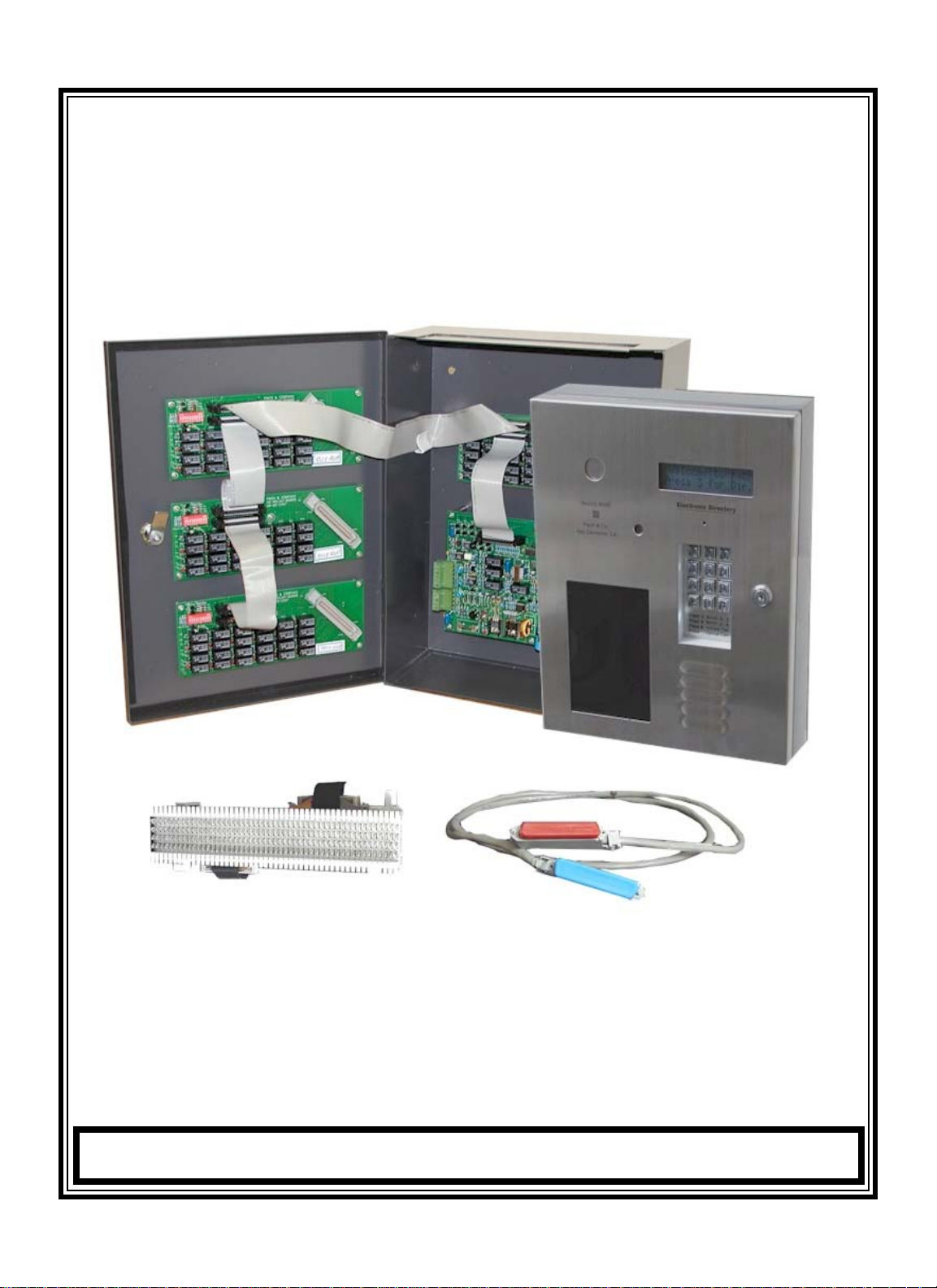
1.3 Unpacking the System
Standard AeGIS NPB9000 Series consists of the following items:
• AeGIS 9000NC and MS79xxx or MX79xxx.
• 2 of XMFR (Power Transformer, 12VAC 40VA).
• 7-pin terminal connector (inside the AeGIS 9000NC)
• Two 5-pin terminal connector (inside the AeGIS 9000NC and the MS79xxx).
• 2 of 3-pin terminal connector (inside AeGIS 9000NC).
• Two 6-pin terminal connector (inside the AeGIS 9000NCand the MS79xxx).
• RJ71X12 or RJ71X24.
• Two Key sets (2 keys per set)
• RJ-11 adapter (inside the AeGIS 9000NC).
• Owners Manual.
Pach and Company Chapter 1 Page 2
AeGIS NPB9000 Series GETTING STARTED 05/01/02

• Warranty Card with unit serial number.
1.4 Limited Warranty
Pach and Company new products are warranted to be free of defects in material or workmanship for a period of two
years, (24 months), from the date of purchase. This warranty extends only to wholesale customers who buy direct
from Pach and Company or through Pach and Company’s normal distribution channels.
Pach and Company does not warrant this product in any way to the end user consumer. Consumers must obtain
warranty information from the selling dealer and/or installer as to the nature of the dealer’s warranty, if any. All contact to Pach and Company from the end user consumer will be referred to the consumer’s selling dealer and/or
installer.
There are no obligations and/or liabilities on the part of Pach and Company for consequential damages arising out
of or in connection with use or performance of Pach and Company products or other indirect damages with respect
to loss of property, revenue, or profit, or cost of removal, installation, or reinstallation. Any use or change to Pach
and Company products not expressly approved by the manufacturer, and performed by an authorized
dealer/installer will immediately void the warranty. All implied warranties, including warranties for marketability as
well as implied warranties for suitability, are valid only until the warranty expires or is voided, whichever comes
first.
This Pach and Company Limited Warranty is in lieu of all other warranties express or implied and all Pach and
Company warranties are subject, but not limited, to the following conditions.
I. NEW PRODUCT POLICY
1. The products must be properly installed as specified; and maintained or used as intended.
2. Cause of product failure is not due to vandalism or malicious mischief, improper installation, abnormal physical or
electrical stress, lightning, power surges, misuse, negligence, accidents, or Natural disasters.
3. Warranty is immediately null and void if the product has been altered, repaired, or modified without express
written authorization from Pach and Company Technical Department, with such authorization given only to
manufacturer approved dealer/installers.
4. Under no circumstances will Pach and Company honor warranty any product found to have been altered, repaired, and/or
modified by the end-user consumer.
5. Pach and Company reserves the right to repair the product, or replace a warranted product with a like product of equal
value in the event original product cannot be repaired.
6. Distributors and/or Dealer-Installer must first obtain a Return Merchandise Authorization (RMA) number from Pach and
Company Technical Department before returning any product to factory for repair, whether under warranty or not. No
returns accepted without RMA.
7. Return Merchandise Authorization (RMA) numbers will not be issued to the end-user consumers. Consumers must
contact their selling dealer-installer for any/all warranty issues.
8. Distributor and/or Dealer-Installer are responsible for all shipping charges, incl. freight and insurance fees, for products
shipped to Pach and Company repair center.
9. Pach and Company warranty does not guarantee any product to be free of operation error or service interruption in any
way during the course of daily product operation.
10. Pach and Company is not responsible for time, travel, and/or labor costs of any distributor and/or dealer-installer,
including but not limited to, any expenses to install, uninstall or reinstall hardware/software/firmware related to warranty
issues, product enhancements, or product failures.
Pach and Company Chapter 1 Page 3
AeGIS NPB9000 Series GETTING STARTED 05/01/02

NEW PRODUCT WARRANTY EXCEPTION
WIEGAND CARD, KEYFOB AND TRANSMITTER
Pach and Company warrants the wiegand card, clam, and keyfob to be free of defects in material or workmanship for a
period of three (3) months from the date of invoice. The above warranty is subject to the following conditions.
1. The products must be properly installed as specified; and maintained or used as intended.
2. Cause of product failure is not due to vandalism or malicious mischief, improper installation, abnormal physical or
electrical stress, lightning, power surges, misuse, negligence, accidents, or Natural disasters.
3. Warranty is immediately null and void if the product has been altered, repaired, or modified without express written
authorization from Pach and Company Technical Department, with such authorization given only to manufacturer approved
dealer/installers.
4. Under no circumstances will Pach and Company honor warranty any product found to have been altered, repaired, and/or
modified by the end-user consumer.
5. Pach and Company reserves the right to repair the product, or replace a warranted product with a like product of equal
value in the event original product cannot be repaired.
6. Distributors and/or Dealer-Installer must first obtain a Return Merchandise Authorization (RMA) number from Pach and
Company Technical Department before returning any product to factory for repair, whether under warranty or not. No returns
accepted without RMA.
7. Return Merchandise Authorization (RMA) numbers will not be issued to the end-user consumers. Consumers must
contact their selling dealer-installer for any/all warranty issues.
8. Distributor and/or Dealer-Installer are responsible for all shipping charges, incl. freight and insurance fees, for products
shipped to Pach and Company repair center.
9. Pach and Company warranty does not guarantee any product to be free of operation error or service interruption in any
way during the course of daily product operation.
10. Pach and Company is not responsible for the time, travel, and/or labor costs of any distributor and/or dealer-
installer, including but not limited to, any expenses to install, uninstall or reinstall hardware/software/firmware related to warranty issues, product enhancements, or product failures.
AeGIS PARTS LIMITED WARRANTY
II. NON-W
ARRANTY REPLACEMENT PARTS POLICY
Pach and Company parts are warranted to be free of defects in material or workmanship for a period of six (6) months), from
the date of purchase or repair. This warranty extends only to wholesale customers who buy direct from Pach and
Company or through Pach and Company’s normal distribution channels. Consumers must obtain warranty information from the selling dealer and/or installer as to the nature of the dealer’s warranty, if any. All contact to Pach and
Company from the end user consumer will be referred to the consumer’s selling dealer and/or installer.
This Pach and Company Limited Warranty is in lieu of all other warranties express or implied and all Pach and
Company warranties are subject, but not limited, to the following conditions.
REPLACEMENT PARTS
1. The products must be properly installed as specified; and maintained or used as intended.
2. Cause of product failure is not due to vandalism or malicious mischief, improper installation, abnormal physical or electrical stress, lightning, power surges, misuse, negligence, accidents, or Natural disasters.
3. Warranty is immediately null and void if the product has been altered, repaired, or modified without express

written authorization from Pach and Company Technical Department, with such authorization given only to manufacturer approved dealer/installers.
4. Under no circumstances will Pach and Company honor warranty any product found to have been altered,
repaired, and/or modified by the end-user consumer.
5. Pach and Company reserves the right to replace a warranted product with a like product of equal value in the event
original system cannot be repaired.
6. Distributors and/or Dealer-Installer must first obtain a Return Merchandise Authorization (RMA) number from Pach and
Company Technical Department before returning any product to factory for repair, whether under warranty or not. No
returns accepted without RMA.
7. Return Merchandise Authorization (RMA) numbers will not be issued to the end-user consumers. Consumers must contact their selling dealer-installer for any/all warranty issues.
8. Distributor and/or Dealer-Installer are responsible for all shipping charges, incl. freight and insurance fees, for products
shipped to Pach and Company repair center.
9. Pach and Company warranty does not guarantee any product to be free of operation error or service interruption
in any way during the course of daily product operation.
10. Pach and Company is not responsible for time, travel, and/or labor costs of any distributor and/or dealer-installer, including but not limited to, any expenses to install, uninstall or reinstall hardware/software/firmware related to warranty issues,
product enhancements, or product failures.
AeGIS NON-WARRANTY REPAIR LIMITED WARRANTY
III. NON-W
ARRANTY REPAIR POLICY
Pach and Company warrants repairs to be free of defects in material or workmanship for a period of three (3) months from
the date of repair and invoice. This warranty extends only to wholesale customers who buy direct from Pach and
Company or through Pach and Company’s normal distribution channels. Consumers must obtain warranty
information from the selling dealer and/or installer as to the nature of the dealer’s warranty, if any. All contact to
Pach and Company from the end user consumer will be referred to the consumer’s selling dealer and/or installer.
This Pach and Company Limited Warranty is in lieu of all other warranties express or implied and all Pach and
Company warranties are subject, but not limited, to the following conditions.
1. The products must be properly re-installed as specified; and maintained or used as intended.
2. Cause of repaired product failure is not due to vandalism or malicious mischief, improper installation, abnormal physical or
electrical stress, lightning, power surges, misuse, negligence, accidents, or Natural disasters.
3. Warranty is immediately null and void if the product has been altered, repaired, or modified without express
written authorization from Pach and Company Technical Department, with such authorization given only to
manufacturer approved dealer/installers.
4. Under no circumstances will Pach and Company honor warranty of any product found to have been altered,
repaired, and/or modified by the end-user consumer.
5. Pach and Company reserves the right to replace a previously repaired product with a like product of equal value in the
event of repair failure, provided repair failure occurs within the specified warranty period.
6. Distributors and/or Dealer-Installer must first obtain a Return Merchandise Authorization (RMA) number from Pach and
Company Technical Department before returning any product to factory for non-warranty repair. No repair returns accepted
without RMA.

7. Return Merchandise Authorization (RMA) numbers will not be issued to the end-user consumers. Consumers must
contact their selling dealer-installer for any/all warranty issues.
8. Distributor and/or Dealer-Installer are responsible for all shipping charges, incl. freight and insurance fees, for products
shipped to Pach and Company repair center.
9. Pach and Company warranty does not guarantee any product, new or repaired, to be free of operation error or
service interruption in any way during the course of daily product operation
10. Pach and Company is not responsible for time, travel, and/or labor costs of any distributor and/or dealer-installer,
including but not limited to, any expenses to install, uninstall or reinstall hardware/software/firmware related to warranty
issues, product enhancements, or product failures.
IMPORT
ANT REP
AIR NOTE: Pach and Company will perform a factory physical evaluation of all products submitted for
repair at receipt of item, and reserves the right to decline repairs after said physical evaluation. In the event a returned
product is deemed ineligible for repair; the product will be returned to sender via common carrier ground at Pach and
Company expense.
Chapter 2
INSTALLATION
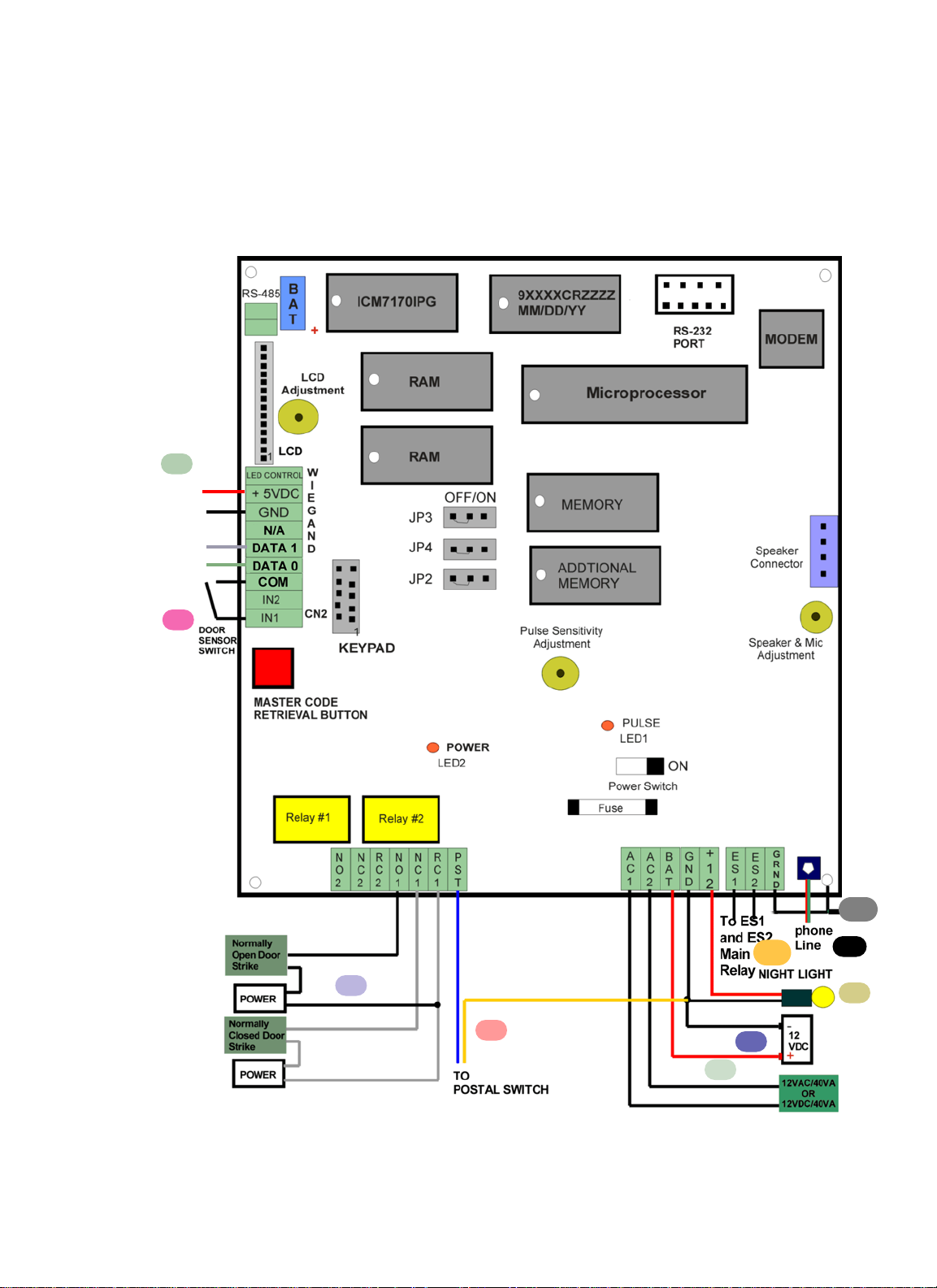
2.1 System’s Wiring
A proper installation of the AeGIS system is very essential. You MUST follow the installation procedures, block diagrams and
installation requirements as specified in this chapter.
Figure 2.1
Pach and Company Chapter 2 Page 4
AeGIS NPB9000 Series INSTALLATION 05/01/02
2
3
4
5
6
7
1
10
RED
BLACK
WHITE
GREEN
9
2ndrelay can be
connected as
Mode 1: Door Control
Mode 2: AShunt
Mode 3: An Alarm
Mode 4: CCTV switch
Battery
Backup
8
Optional 26 Bit
Wiegand Card
Reader or
Wiegand
Radio Reader
Input. We will
not resposible
for
incompatibility
issue if using
other than
Pach & Co
Proximity
Reader.
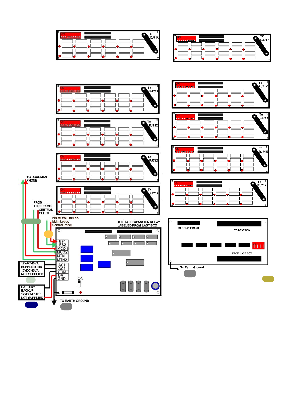
Pach and Company Chapter 2 Page 5
AeGIS NPB9000 Series INSTALLATION 05/01/02
1
1
11
13
12
2
14
MAIN RELAY CONTROL PANEL
MS79012 - MS79120
EXPANSION RELAY PANEL
MX79012 - MX79120
Figure 2.2
GROUNDING
Grounding the AeGIS 9000NC, MS79xxx and MX79xxx steel enclosure are essential. Please comply with all local
ordinances and industry standard procedures to ensure a complete and safe ground. Recommended earth grounds are:
• Use 18-gauge solid wire for grounding.
• Installing a ground steel rod from the steel enclosure to the earth ground, use the same grounding point for best ground.
• Installing a solid heavy gauge wire from the AeGIS steel enclosure to a water pipe.
• Connecting the AeGIS steel enclosure to any earth grounded steel metal.
• Use the same ground point for all the systems to avoid cross-talk problem.
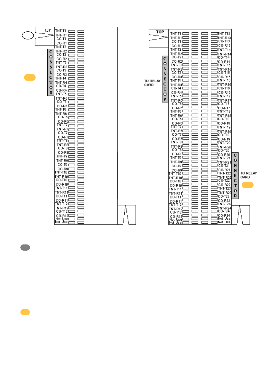
COMMUNICATION LINE
Always use AeGIS AC/Telephone Surge Protector (ASP1) to protect your investment.
RJ71X12
RJ71X24
Figure 2.3a
Figure 2.3b
1
Pach and Company Chapter 2 Page 6
AeGIS NPB9000 Series INSTALLATION 05/01/02
2
14
15
15
• Two Conductors, 18-gauge shielded stranded must be used for communication. Ground only one end of the
shielded to the earth ground. Use the same earth ground for best ground.
See installation instruction if ASP1 Surge Protector is used.
• Up to eight AeGIS 9000NC can be connected to the Main Relay Control Panel.
DOOR STRIKE OR ELECTRICAL STRIKE
The AeGIS NPB9000 Series provides TWO relay form "C" dry contact: Normally Open (NO) and Normally Closed (NC).
• 10 Ampere 120 VAC or
• 10 Ampere 24 VDC or
• 7 Ampere 250 VAC
See figure 2.1 for door strike wiring diagram. You MUST use two conductors 18 gauge stranded wire minimum.
Note: Some door strikes are creating electrical or magnetic noise or spikes and could create problem to the system's
memory. Although the system's relay has built-in filtration circuit, installing an isolation relay is recommended if the
system is experiencing with looses memory.
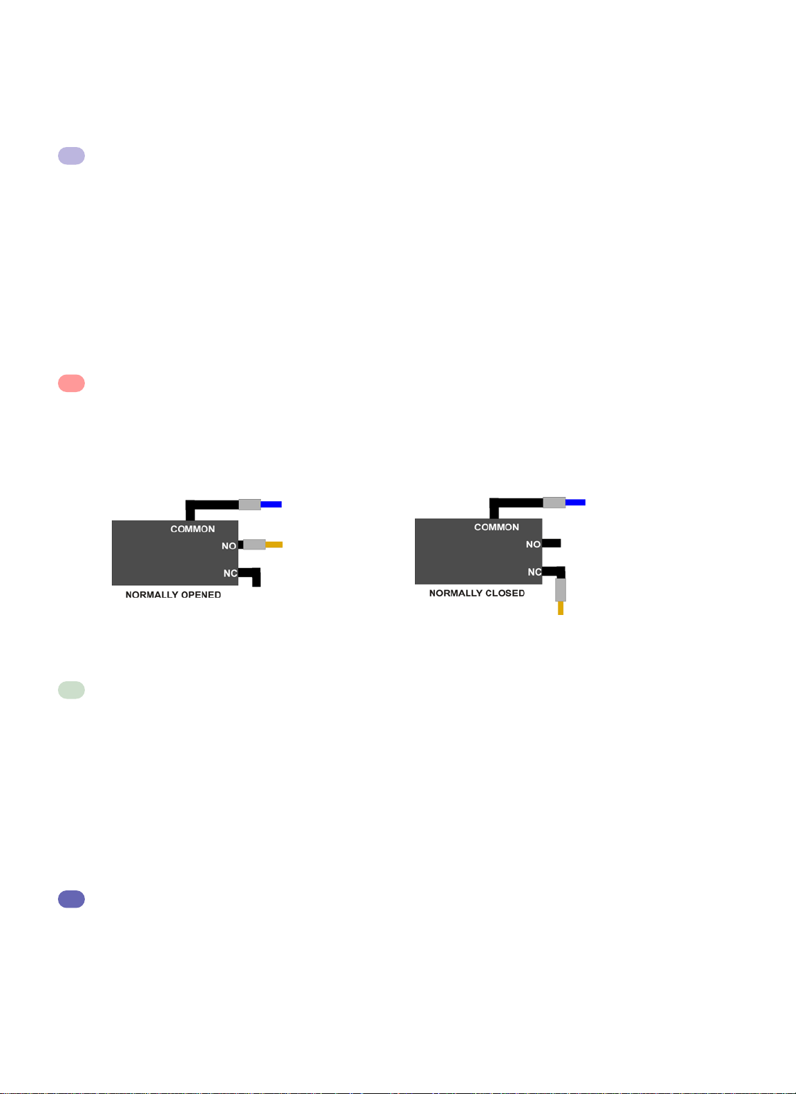
POSTAL LOCK
The AeGIS system comes with pre-wired "Normally Open" postal switch as shown on figure 2.2(a). If the postal switch is
pressed, the gate will open. If you need "Normally Closed" postal switch, see figure 2.2(b).
The postal lock is not included. You have to purchase the postal lock from your local post office. See figure 2.2 to alter the
postal switch to normally closed.
MAIN LOBBY PANEL POWER
A 12 VAC 40VA transformer is supplied by Pach and Company. However, 12 VDC 40VApower supply or 12VDC power
supply with battery backup can be used to power the AeGIS 7000NC, use the same connection as shown on figure 2.1.
• Two conductors, 18-gauge wire must be used. See installation instruction if ASP1 Surge Protector is used.
• Do not share power transformer or power supply between the AeGIS 9000NC and other electronic equipment.
• Turn the power "ON" (left position). The Power Light Emitting Diode (LED2) should be "ON". You should see
“Welcome to Pach's Telephone Access Systems" on the Liquid Crystal Display (LCD). If the display is blank, turn
the system off and see Chapter 4.0 Operations and Chapter 6.0 Trouble Shooting Guides.
• If 12 VDC 40VA with or without built-in battery backup is used, the output voltage must be
13.5 VDC - 14.0 VDC.
MAIN LOBBY PANEL BATTERY BACKUP
The Main Lobby Panel has a built-in charging circuit for battery backup. The battery will keep the system in full operation during power failure. Recommended battery is 12 VDC, 4.5 Ahr rechargeable (customer supply). The life of the battery is
approximately 8 hours in idle mode.
Pach and Company Chapter 2 Page 7
AeGIS NPB9000 Series INSTALLATION 05/01/02
3
4
Figure 2.2 (a)
Figure 2.2 (b)
LCOM
POST
LCOM
POST
5
6

• Use two conductors 8-gauge shielded stranded wires.
WARNING: The connection is polarity sensitive. Connect the battery (+) terminal to the connector labeled (BAT) on the
AeGIS and the battery (-) terminal to the connector labeled LCOM on the AeGIS. See figure 2.1 for wiring
diagram.
NIGHT LIGHT
14V 0.080A 15,000 Average life hours light bulbs. Use the same rating of replacement light bulb.
TELEPHONE LINE
Optional telephone line for remote programming.
OPTIONAL 26 BIT WIEGAND CARD READER OR RADIO READER
ONLY USE FOR PACH & CO READER OR RADIO READER OTHERWISE INCOMPATIBILITY MAY OCCUR.
OPTIONAL
DOOR SENSOR
Optional Normally Open door sensor switch can be installed to warn the manager if the gate is left open or forced open.
MAIN RELAY CONTROL PANEL POWER
A 12 VAC 40VA transformer is supplied by Pach and Company. However, 12 VDC 40VApower supply or 12VDC power
supply with battery backup can be used to power the AeGIS NPB9000 Series, use the same connection as shown on figure
2.1.
• Two conductors, 18-gauge shielded stranded wires must be used. Ground one end of the shielded to earth
ground. See installation instruction if ASP1 Surge Protector is used.
• Do not share power transformer or power supply between the AeGIS and other electronic equipment.
• Turn the power "ON" (left position). The Power Light Emitting Diode (LED2) should be "ON". You should see
“Welcome to Pach's Telephone Access Systems" on the Liquid Crystal Display (LCD). If the display is blank, turn
the system off and see Chapter 4.0 Operations and Chapter 6.0 Trouble Shooting Guides.
• If 12 VDC power supply is used, the OUTPUT must read between 13.5 VDC - 14.5 VDC. Note: Do not use a
power supply higher than 12 VDC.
MAIN RELAY CONTROL PANEL BATTERY BACKUP
The Main Relay Control Panel has a built-in charging circuit for battery backup. The battery will keep the system in full
operation during power failure. Recommended battery is 12 VDC, 4.5 Ahr rechargeable (customer supply). The life of the
battery is approximately 8 hours in idle mode.
• Use two conductors 18-gauge shielded stranded wires.
WARNING: The connection is polarity sensitive. Connect the battery (+) terminal to the connector labeled (BAT) on the
AeGIS and the battery (-) terminal to the connector labeled LCOM on the AeGIS. See figure 2.1 for wiring
diagram.
DOORMAN PHONE
You must have a central office telephone line input on MCO1 and MCO2 to use the doorman phone. The door man phone is
connected to MTN1 and MTN2. See figure 2.2.
• Use two conductors 22-twisted wire.
Pach and Company Chapter 2 Page 8
AeGIS NPB9000 Series INSTALLATION 05/01/02
7
9
8
10
11
12
13
 Loading...