

Pach and Company AWRR User Manual

Enclosure Construction: Weather-resistant, anodized alu-
minum enclosure with removable end caps to provide wiring
and programming access; end caps secured with screws.
Shipping Weight: 3.0 Lbs. approximate.
Warranty: “Two Years Warranty”.
Output Data: Data 0 and Data 1 standard Wiegand
electrical and protocol interface.
Operating Environment: -22°F to +155°F.
Mount: Inside the AeGIS 9000 Series or Outside.
INTRODUCTION
Pach and Company thanks and conratulates you on the purchase of
your AeGIS Wiegand Radio Reader (AWRR) and transmitter (AWRT).
The AWRR is designed to interface with AeGIS 9000 Series. The
AWRR will be installed inside the AeGIS 9000 Series if order at the
same time at no extra cost for installtion. The antenna will be mounted
on top of the system.
SPECIFICATIONS
Power Input: 5.0 - 24 VDC Regulated (5 VDC is supplied by the
AeGIS 9000 Series).
Current Consumption: 30 mA operating.
Radio Frequency:
318 Mhz
LO Reradiation: 200 microVolt/meter @ 3 meters (maximum)
Data Format: MegaCode
Sensitivity: -100dBm minimum
Desensitivity: 20 dB manual attenuation at the antenna input
Antenna: 9-1/2 in whip antenna with F-connector (supplied).
Bandwidth: 300 Khz
Image Rejection: 40 dB.
INSTALLATION
Figure 1
Step 1 Set JP1 to 5VDC if the AWRR is connected to the AeGIS 9000 Series (see fig. 1). If the AWRR purchased as a package
with the AeGIS 9000 Series, the systems are prewired from the manufacturer.
Step 2 Turn the power OFF on the AeGIS 9000 Series.
Step 3 Connect the wires as shown on fig.1.
Step 4 Turn the AeGIS 9000 power ON.
Step 5 The Red LED will turn ON then the Green LED will flicker and the Red LED will turn OFF.
Step 6 Install the antenna on top of the AeGIS 9000 Series.
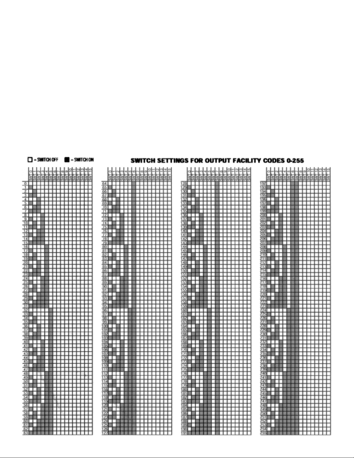
SET OUTPUT FACILITY CODE
Step 1 Set the WIEGAND OUPUT FORMAT to 26-BIT (see figure 1 to locate the DIP SWITCH (A), switch #1).
Step 2 Set the OUTPUT FACILITY CODE (see fig. 1 DIP SWITCH (C) is labeled OUTPUT (0-7)). See table below to set the facility
code. Warning: Do not follow the number labeled on the DIP SWITCH.
 Loading...