


NANO 2000T Polisher
- - - - - - - - - - - - - - - - - - - - - - - - - - - - - - - - - - - - - - - - - - - - - - - - - - ▲ INSTRUCTION MANUAL
3601 E. 34th St. Tucson, AZ 85713 USA Tel. +1 520-882-6598 Fax +1 520-882-6599 email: pace@metallographic.com Web: http://www.metallographic.com
Equipment Type: 8 and 10-inch diameter Double Grinder /
Model:
Electrical Requirements: 110 / 220 Volts (single-phase)
Frequency: 50/60 Hz
Motor Horsepower: 1 hp (750 W)
Manual Revision Date: March 8, 2016
Please read this instruction manual carefully and follow all installation, operating and safety guidelines.
Polisher
NANO 2000T

NANO 2000T Polisher
- - - - - - - - - - - - - - - - - - - - - - - - - - - - - - - - - - - - - - - - - - - - - - - - - - ▲ INSTRUCTION MANUAL
3601 E. 34th St. Tucson, AZ 85713 USA Tel. +1 520-882-6598 Fax +1 520-882-6599 email: pace@metallographic.com Web: http://www.metallographic.com
Contents
PAGE
Warranty
1.0 Product Description
2.0 Unpacking, Shipping and Installation
3.0 Safety Guidelines
4.0 Start-Up and Operation
5.0 Maintenance
6.0 Trouble Shooting
7.0 Metallographic Consumables
ii
1
4
6
8
20
21
22
8.0 Spare Parts
9.0 Schematics
Please read this instruction manual carefully and follow all installation, operating and safety guidelines.
25
39
i

NANO 2000T Polisher
- - - - - - - - - - - - - - - - - - - - - - - - - - - - - - - - - - - - - - - - - - - - - - - - - - ▲ INSTRUCTION MANUAL
3601 E. 34th St. Tucson, AZ 85713 USA Tel. +1 520-882-6598 Fax +1 520-882-6599 email: pace@metallographic.com Web: http://www.metallographic.com
WARRANTY
.Terms and Conditions applying to all PACE Technologies Products
1. LIMITED WARRANTY AND DISCLAIMER:
PACE Technologies Products are warranted for one year from the purchase date to be free from defects in
material and workmanship under correct use, normal operating conditions, and proper application. PACE
Technologies obligation under this warranty shall be limited to the repair or exchange, at PACE
Technologies option, of any PACE Technologies Product or part which proves to be defective as provided
herein. PACE Technologies reserves the right to either inspect the product at Buyer’s location or require it
to be returned to the factory for inspection. Buyer is responsible for freight to and from factory on all
warranty claims. The above warranty does not extend to goods damaged or subjected to accident, abuse or
misuse after release from PACE Technologies warehouse, nor goods altered or repaired by anyone other
than specifically authorized PACE Technologies representatives. PACE Technologies shall not in any way
be responsible for the consequences of any alteration, modification or misuse unless previously approved in
writing by an officer of PACE Technologies.
PACE TECHNOLOGIES MAKES NO EXPRESS WARRANTIES OTHER THAN THOSE WHICH ARE
SPECIFICALLY DESCRIBED HEREIN. Any description of the goods sold hereunder, including any
reference to Buyer’s specifications and any description in catalogs, circulars and other written material
published by PACE Technologies, is the sole purpose of identifying such goods and shall not create an
express warranty that the goods shall conform to such description.
THIS WARRANTY IS EXPRESSLY IN LIEU OF ALL OTHER WARRANTIES, EXPRESSED OR
IMPLIED. THERE ARE NO IMPLIED WARRANTIES OF MECHANTABILITY OR FITNESS FOR
PARTICULAR PURPOSE. THIS WARRANTY STATES PACE TECHNOLOGIES ENTIRE AND
EXCLUSIVE LIABILITY AND BUYER’S EXCLUSIVE REMEDY FOR ANY CLAIM FOR DAMAGES
IN CONNECTIONS WITH PACE TECHNOLOGIES PRODUCTS. PACE TECHNOLOGIES WILL IN
NO EVENT BE LIABLE FOR INCIDENTAL OR CONSEQUENTIAL DAMAGES WHATSOEVER,
NOR FOR ANY SUM IN EXCESS OF THE PURCHASE PRICE.
2. LIABILITY CAP:
PACE Technologies maximum aggregate liability for loss and damage arising under, resulting from or in
connection with the supply or use of the Equipment and Consumables provided under this purchase, or from
the performance or breach of any obligation (s) imposed hereunder, whether such liability arises from any
one or more claims or actions for breach of contract, tort, (including negligence), delayed completion,
warranty, indemnity, strict liability or otherwise, unless otherwise limited by the terms hereof, shall be
limited to one hundred percent (100%) of the purchase price.
3. DELIVERY:
Customer assumes and shall bear the risk of all loss or damage to the Products from every cause whatsoever,
whether or not insured, and title to such Products shall pass to Customer upon PACE Technologies delivery
of the Products to the common carrier of Pace Technologies choice, or the carrier specified in writing by
Customer, for shipment to Customer. Any claims for breakage, loss, delay, or damage shall be made to the
carrier by the Customer and Pace Technologies will render customer reasonable assistance in prosecuting
such claims.
Please read this instruction manual carefully and follow all installation, operating and safety guidelines.
ii

NANO 2000T Polisher
- - - - - - - - - - - - - - - - - - - - - - - - - - - - - - - - - - - - - - - - - - - - - - - - - - ▲ INSTRUCTION MANUAL
3601 E. 34th St. Tucson, AZ 85713 USA Tel. +1 520-882-6598 Fax +1 520-882-6599 email: pace@metallographic.com Web: http://www.metallographic.com
4. ACCEPTANCE:
Customer shall inspect the Products promptly upon receipt of delivery. Unless customer objects in writing
within thirty (30) business days thereafter, customer shall be deemed to have accepted the Products. All
claims for damages, errors, or shortage in Products delivered shall be made by Customer in writing within
such five (5) business day period. Failure to make any claim timely shall constitute acceptance of the
Products.
5. PAYMENT:
Customer agrees to provide timely payment for the Products in accordance with the terms of payment set
forth on the reverse side hereof or in any proposal submitted herewith. If any payment is not paid on or
before its due date, Customer shall pay interest on such late payment from the due date until paid at the
lesser of 12% per annum or the maximum rate allowed by law.
6. DEFAULT:
If Buyer is in default (including, but not limited to, the failure by Buyer to pay all amounts due and payable
to Seller) under the work or purchase order or any other agreement between Buyer and Seller, Buyer’s rights
under the warranty shall be suspended during any period of such default and the original warranty period
will not be extended beyond its original expiration date despite such suspension of warranty rights.
7. MISCELLANEOUS PROVISIONS:
This agreement has been made in and shall be governed by the laws of the State of Arizona. These terms
and conditions and the description of the Products on the reverse side hereof or in any proposal submitted
herewith constitute the entire agreement and understanding of the parties with respect to this sale and
supersede all prior and contemporaneous agreements or understandings, inducements or representations,
expressed or implied, written or oral, between the parties with respect hereto. Any term or provision of this
Agreement may be amended, and any observance of any term of this Agreement may be waived, only by a
writing signed by the party to be bounds. The waiver by a party of any breach shall not be deemed to
constitute a waiver of any other breach. Should suit be brought on this Agreement, the prevailing party shall
be entitled to recover its reasonable attorneys’ fees and other costs of suit including costs and attorneys’ fees
incurred on appeal or in collection of any judgment.
Please read this instruction manual carefully and follow all installation, operating and safety guidelines.
iii

NANO 2000T Polisher
- - - - - - - - - - - - - - - - - - - - - - - - - - - - - - - - - - - - - - - - - - - - - - - - - - ▲ INSTRUCTION MANUAL
3601 E. 34th St. Tucson, AZ 85713 USA Tel. +1 520-882-6598 Fax +1 520-882-6599 email: pace@metallographic.com Web: http://www.metallographic.com
1.0 Product Description
1.1 General Description
Water valve
Hard coat
anodized
working wheel
Time display
Emergency
Stop button
Speed display
The NANO 2000T is a 8 or 10-inch single wheel grinding/ polishing machine for manual wet
grinding or polishing of metallographic specimens.
The NANO 2000T is a variable speed (0-1000 rpm) with three programmable fast speed
buttons (approx. 100, 200 and 300 rpm) polisher. For semi-automated grinding / polishing the
FEMTO Polishing head can added.
Please read this instruction manual carefully and follow all installation, operating and safety guidelines.
Water switch
1

NANO 2000T Polisher
- - - - - - - - - - - - - - - - - - - - - - - - - - - - - - - - - - - - - - - - - - - - - - - - - - ▲ INSTRUCTION MANUAL
3601 E. 34th St. Tucson, AZ 85713 USA Tel. +1 520-882-6598 Fax +1 520-882-6599 email: pace@metallographic.com Web: http://www.metallographic.com
1.2 Technical Specifications
Electrical specifications: 110 / 220V (50/60 Hz) (single phase
input - motor runs on 3-phase power
for more torque)
Working wheel: 8-inch (200 mm) or
10-inch (250 mm) diameter
Motor power: 1 hp (750 hp)
Polishing base speed:
Weight: Approx. 150 lbs (70 kg)
Dimensions (WxHxD): Approx. 30” x 13” x 28”
Working temperature: 32° - 100°F (0 - 40°C)
Shipping temperature: 32° - 100°F (0 - 40°C)
Storage temperature: 32° - 100°F (0 - 40°C)
Maximum part size 1/3-diameter of working wheel
EU Directives: Machinery directive 2006/42/EC
Low Voltage Directive 2006/95/EC
Electromagnetic Compatibility directive 2004/108/EC
EU Harmonized Standards: EN ISO 1200:2010
EN 61010-1:2010
EN 61326-1:2006
0 to 1000 rpm variable speed (20
rpm increments). Fast speed
buttons pre-programmed for 100,
200 and 300 rpm)
(760 mm x 330 mm x 710 mm)
Please read this instruction manual carefully and follow all installation, operating and safety guidelines.
2

NANO 2000T Polisher
- - - - - - - - - - - - - - - - - - - - - - - - - - - - - - - - - - - - - - - - - - - - - - - - - - ▲ INSTRUCTION MANUAL
3601 E. 34th St. Tucson, AZ 85713 USA Tel. +1 520-882-6598 Fax +1 520-882-6599 email: pace@metallographic.com Web: http://www.metallographic.com
1.3 Mechanical Schematic
Note: Installation of the NANO 2000T
should be on a flat sturdy surface, with
easy access to drain, water and
electrical connections.
1.4 Features
The NANO 2000T is equipped with a
powerful motor, connected to the polishing
wheel through a maintenance-free V-belt.
Please read this instruction manual carefully and follow all installation, operating and safety guidelines.
3

NANO 2000T Polisher
- - - - - - - - - - - - - - - - - - - - - - - - - - - - - - - - - - - - - - - - - - - - - - - - - - ▲ INSTRUCTION MANUAL
3601 E. 34th St. Tucson, AZ 85713 USA Tel. +1 520-882-6598 Fax +1 520-882-6599 email: pace@metallographic.com Web: http://www.metallographic.com
2.0 Unpacking, Shipping and Installation
2.1 Unpacking
2.2 Shipping
Unit is delivered in a box. Unpack and check for completeness of
parts.
Measures WxHxD: 34” x 34” x 20”
Weight: Varies, depending upon model
(approximately 190 lbs).
When moving box, lift from bottom.
! Caution: Heavy equipment. Take care to avoid bodily injury.
Please read this instruction manual carefully and follow all installation, operating and safety guidelines.
4

NANO 2000T Polisher
- - - - - - - - - - - - - - - - - - - - - - - - - - - - - - - - - - - - - - - - - - - - - - - - - - ▲ INSTRUCTION MANUAL
3601 E. 34th St. Tucson, AZ 85713 USA Tel. +1 520-882-6598 Fax +1 520-882-6599 email: pace@metallographic.com Web: http://www.metallographic.com
2.3 Installation
Install unit carefully! Improper installation voids warranty.
!
The NANO 2000T should be placed on a flat stable surface.
Connect to air, water supply, drain and electrical connections.
After water, drain and electrical connections are completed, the system is ready for
operation by activating the main power switch.
Backside connections
FEMTO connections
Electrical connection
110V or 220V
External water
supply
External water supply: The water supply line requires a 1/4-inch compression fitting. It is
Electrical connection: Connect six-foot electrical power cable to source.
Drain connection: Connect drain so that it exits the machine in the direction best
Please read this instruction manual carefully and follow all installation, operating and safety guidelines.
Water drain
Connect drain for best
direction to drain with
fittings
recommended that the water supply be turned off when the unit is
not in use. Inlet water should be clean and contamination-free to
extend the life and performance of the systems.
suited to the drain site
5

NANO 2000T Polisher
- - - - - - - - - - - - - - - - - - - - - - - - - - - - - - - - - - - - - - - - - - - - - - - - - - ▲ INSTRUCTION MANUAL
3601 E. 34th St. Tucson, AZ 85713 USA Tel. +1 520-882-6598 Fax +1 520-882-6599 email: pace@metallographic.com Web: http://www.metallographic.com
3.0 Safety Guidelines
3.1 Warning Sign
This sign points to special safety features on the machine.
!
3.2 Safety Precautions
Careful attention to this instruction manual and the recommended safety guidelines is
!
essential for the safe operation of the NANO 2000T.
Proper operator training is required for operation of the NANO 2000T. Any unauthorized
mechanical and electrical change, as well as improper operation, voids all warranty
!
claims. All service issues need to be reported to the manufacturer / supplier.
!
!
!
!
Operate unit as specified in this manual.
Disconnect power before opening unit.
Do not leave any specimen or other parts on the working wheel.
Ensure that the air slots on polishing base are not obstructed.
!
!
3.3 Emergency Statement
Always follow proper operational guidelines and avoid contact with lubricants and abrasives.
Seek appropriate medical care for cutting injuries.
Please read this instruction manual carefully and follow all installation, operating and safety guidelines.
When unit is not in use turn off water.
Securely hold the sample, preferably with two hands.
6

NANO 2000T Polisher
- - - - - - - - - - - - - - - - - - - - - - - - - - - - - - - - - - - - - - - - - - - - - - - - - - ▲ INSTRUCTION MANUAL
3601 E. 34th St. Tucson, AZ 85713 USA Tel. +1 520-882-6598 Fax +1 520-882-6599 email: pace@metallographic.com Web: http://www.metallographic.com
3.4 Safety Test
Examine and verify that the NANO 2000T safety devices and operating performance are in
!
good working condition prior to use. The following safety check is considered important:
Emergency stop switch
Emergency stop switch
Test:
Proper
Response:
Malfunction: Machine does not lose power.
Corrective
measure:
Please read this instruction manual carefully and follow all installation, operating and safety guidelines.
Activate main switch.
Depress emergency stop switch.
Machine powers down.
If system does not power down,
disconnect power supply cord and call
service technician.
7

NANO 2000T Polisher
- - - - - - - - - - - - - - - - - - - - - - - - - - - - - - - - - - - - - - - - - - - - - - - - - - ▲ INSTRUCTION MANUAL
3601 E. 34th St. Tucson, AZ 85713 USA Tel. +1 520-882-6598 Fax +1 520-882-6599 email: pace@metallographic.com Web: http://www.metallographic.com
4.0 Start-up and Operation
4.1 General
The NANO 2000T is a hand grinding/ polishing machine. By adding the FEMTO power head,
semi-automated polishing can be accomplished.
4.2 Control Panel
Programming mode
Auto-mode for timed
grinding/ polishing
Water
switch
Preset speeds
(Low, medium, high)
Emergency stop button: Emergency stop switch cuts power to the motor immediately.
Wheel direction: Clockwise rotation or counter clockwise rotation.
Start / stop buttons: Start/stop the polishing wheel in both manual and auto mode.
Water switch: Activates the water solenoid for the rinse bowl and rinse spout.
Preset speeds: Allows for faster speed control, SPL - low speed, SPM - medium
speed, SPH - high speed (factory setting approx. 100, 200, 300
rpm.
Auto-mode: Allows for running pre-programmed speeds and times (factory
setting approx. 200 rpm, FWD, 30 seconds).
Please read this instruction manual carefully and follow all installation, operating and safety guidelines.
Wheel direction
Start/Stop
8

NANO 2000T Polisher
- - - - - - - - - - - - - - - - - - - - - - - - - - - - - - - - - - - - - - - - - - - - - - - - - - ▲ INSTRUCTION MANUAL
3601 E. 34th St. Tucson, AZ 85713 USA Tel. +1 520-882-6598 Fax +1 520-882-6599 email: pace@metallographic.com Web: http://www.metallographic.com
4.2.1 Direction and speed controller (manual)
1. To change direction of the wheel:
-Press clockwise or counter clockwise button,
LED will light
2. To change the speed of the wheel:
Select low, medium or high speed fast buttons
and use up and down arrows to fine tune speed
if required
4.2.1 Programmable Mode
1. The programming mode can be used to pre-set the
polishing speed, direction and time for automated
polishing. It can also be used to change the fast speed
buttons.
Fast speed buttons
2. To change the speed of the wheel:
Press the PRG button and use the up and down keys
to SP1 and press ENTER. Use the up and down < key
to change the speed. Press ENTER to save.
3. To program a grinding/ polishing time:
Press the PRG button and use the up and down keys
to t1 and press ENTER. Use the up and down < key to
change the time (enter in seconds - displayed min-sec)
4. To operate the pre-programmed conditions:
PRESS the AUTO button and then start the program
with the RUN/STOP button. The pre-programmed
conditions will be executed.
To change the speed setting for
the fast speed buttons use the
following procedure:
Press the PRG button and use
the up and down keys to SL
(slow speed) and press ENTER.
Use the up and down < key to
change the speed. Use Sn for
changing the medium speed
and SH for the fast speed.
4.3 Grinding / polishing by hand
1. Install working wheel and attach grinding papers / polishing cloths.
2. Switch on the machine in the back and set the mode, speed, and time (if required).
3. Position flexible water spout over working wheel. During sample preparation adjust water
flow by turning water control knob as required. Note: Initial operation of water valve may
contain air in the lines. Turn water on slowly to purge air from system.
4. Press START/STOP start and stop the machine in the manual mode.
Please read this instruction manual carefully and follow all installation, operating and safety guidelines.
9

NANO 2000T Polisher
- - - - - - - - - - - - - - - - - - - - - - - - - - - - - - - - - - - - - - - - - - - - - - - - - - ▲ INSTRUCTION MANUAL
3601 E. 34th St. Tucson, AZ 85713 USA Tel. +1 520-882-6598 Fax +1 520-882-6599 email: pace@metallographic.com Web: http://www.metallographic.com
4.4 Metallographic Specimen Preparation Basics
A typical metallographic specimen preparation consists of the following basic steps:
Preparation Stage Purpose
Initial documentation:
Sectioning / cutting:
Rough, or planar grinding
(refer to Section 4.4.1):
Rough polishing (refer to
Section 4.4.2):
Final polishing (refer to
Section 4.4.1)::
Etching:
Examination:
To document the initial condition of the sample,
To map the sample surface,
To highlight the area of interest.
To reduce the size of large samples and to sample the
specimens close to the area of interest.
To obtain a planar surface,
To remove sectioning damage,
To approach the area of interest.
Ideally to remove all the subsurface damage and microstructural
damage produced during cutting and rough grinding (Superficial
scratches may still be present after this step).
Generally, more for cosmetic purposes than for removing
microstructural damage. In most cases, this stage should be
minimized to avoid overpolishing and distorting the
microstructural features.
To enhance microstructural features such as grain boundaries,
grain size, phase differences, etc.
A variety of examination techniques are used in metallography,
including: optical microscopy, electron microscopy and hardness
testing.
Please read this instruction manual carefully and follow all installation, operating and safety guidelines.
10

NANO 2000T Polisher
- - - - - - - - - - - - - - - - - - - - - - - - - - - - - - - - - - - - - - - - - - - - - - - - - - ▲ INSTRUCTION MANUAL
3601 E. 34th St. Tucson, AZ 85713 USA Tel. +1 520-882-6598 Fax +1 520-882-6599 email: pace@metallographic.com Web: http://www.metallographic.com
4.4.1 Rough / Planar Grinding
Rough or planar grinding, is required to produce flat specimens and to reduce the damage created
by sectioning. The planar grinding step is accomplished by decreasing the abrasive grit particle size
sequentially to obtain surface finishes that are ready for polishing. Care must be taken to avoid being
too abrasive in this step, and actually creating greater specimen damage than produced during
cutting. This is especially true for very brittle materials such as ceramics and silicon.
The machine parameters which affect the preparation of metallographic specimens include: grinding /
polishing pressure, grinding direction, and the relative velocity distribution between the specimen and
the polishing wheel.
Grinding Pressure
Grinding / polishing pressure is dependent upon the applied force (pounds or Newton's) and the area
of the specimen and mounting material. Pressure is defined as the Force/Area (psi, N/m2 or Pa). For
specimens significantly harder than the mounting compound, pressure is better defined as the force
divided by the specimen surface area. Thus, for larger hard specimens, higher grinding / polishing
pressures increase stock removal rates. However, higher pressure also increases the amount of
surface and subsurface damage produced in the specimen.
Note regarding SiC grinding papers: as the abrasive grains dull and cut rates decrease, increasing
grinding pressures can extend the life of the SiC paper.
Higher grinding / polishing pressures can also generate additional frictional heat which may be
beneficial for the chemical mechanical polishing (CMP) of ceramics, minerals and composites.
Likewise for extremely friable specimens (such as nodular cast iron), higher pressures and lower
relative velocity distributions can aid in retaining inclusions and secondary phases.
Grinding Direction
The orientation of the specimen can have a significant impact on the preparation results, especially
for specimens with coatings. In general, when grinding and polishing materials with coatings, the
brittle component should be kept in compression. In other words, for brittle coatings, the direction of
the abrasive should be through the coating and into the substrate. Conversely, for brittle substrates
with ductile coatings, the direction of the abrasive should be through the brittle substrate and into the
ductile coating.
Manual Preparation
In order to ensure that the previous rough grinding damage is removed when grinding by hand, the
specimen should be rotated 90 degrees and continually ground until all of the scratches from the
previous grinding direction are removed. When necessary, the abrasive paper should be replaced
with a newer paper to maintain cutting rates.
Please read this instruction manual carefully and follow all installation, operating and safety guidelines.
11

NANO 2000T Polisher
- - - - - - - - - - - - - - - - - - - - - - - - - - - - - - - - - - - - - - - - - - - - - - - - - - ▲ INSTRUCTION MANUAL
3601 E. 34th St. Tucson, AZ 85713 USA Tel. +1 520-882-6598 Fax +1 520-882-6599 email: pace@metallographic.com Web: http://www.metallographic.com
4.4.2 Rough Polishing
The purpose of the rough polishing step is to remove the damage produced during cutting and planar
grinding. Proper rough polishing will maintain specimen flatness and retain all inclusions or
secondary phases. By eliminating the previous damage and maintaining the microstructural integrity
of the specimen at this step, a minimal amount of time is required to remove the cosmetic damage at
the final polishing step.
Rough polishing is accomplished primarily with diamond abrasives ranging from 9 micron to 1
micron. Polycrystalline diamond -- because of its multiple and small cutting edges -- produces high
cut rates with minimal surface damage. Therefore, polycrystalline diamond abrasives are
recommended for metallographic rough polishing on low-napped polishing cloths.
Rough Polishing Guidelines
Material Recommendations
Metals (ferrous, non-ferrous,
tool steels, superalloys, etc.)
Ceramics and ceramic matrix
composites (CMC)
Polymer matrix composites
(PMC)
Biomaterials
Microelectronic specimens Diamond-lapping films are recommended.
Plastics and polymers 800 and 1200 grit SiC abrasive paper are recommended.
Plasma spray materials
Rough polishing typically requires two polishing steps, e.g., a 6micron diamond followed by a 1-micron diamond on low-napped
polishing cloths.
Low-nap polishing pads using polycrystalline diamond, alternating
with colloidal silica. This provides a chemical mechanical
polishing (CMP) effect which results in a damage-free surface
Diamond-lapping films are recommended.
Low-napped polishing pads with polycrystalline diamond,
alternating with colloidal silica. Alternatively, diamond-lapping
films may work well.
Diamond-lapping films or low-napped polishing pads with
alternating diamond and colloidal silica abrasives.
Please read this instruction manual carefully and follow all installation, operating and safety guidelines.
12

NANO 2000T Polisher
- - - - - - - - - - - - - - - - - - - - - - - - - - - - - - - - - - - - - - - - - - - - - - - - - - ▲ INSTRUCTION MANUAL
3601 E. 34th St. Tucson, AZ 85713 USA Tel. +1 520-882-6598 Fax +1 520-882-6599 email: pace@metallographic.com Web: http://www.metallographic.com
4.4.3 Final Polishing
The purpose of final polishing is to remove only the cosmetic surface damage. It should not be used
to remove any damage remaining from cutting and planar grinding. If the damage from these steps is
not completely removed, the rough polishing step should be repeated or continued.
Final Polishing Guidelines
Material Recommendation
Metals (ferrous, nonferrous, tool steels,
superalloys, etc.)
Ceramics and ceramic
matrix composites (CMC)
Polymer matrix composites
(PMC)
Biomaterials
Microelectronic specimens
Plastics and polymers Light polish with alumina on a high-napped polishing pad.
Plasma spray materials
High-napped polishing pads with a nanometer alumina polishing
abrasive. The polishing times should nominally be less than 30
seconds.
Low-napped polishing pads using 1-um polycrystalline diamond,
alternating with colloidal silica or colloidal silica alone.
Fine abrasive diamond-lapping films, followed by a very light polish
on a high-napped polishing pad.
Low-napped polishing pads with polycrystalline diamond, alternating
with colloidal silica.
Diamond-lapping films followed by a very light polish on a
high-napped polishing pad.
Diamond-lapping films followed by a very light and short alumina or
colloidal silica polish on a high-napped polishing pad.
Please read this instruction manual carefully and follow all installation, operating and safety guidelines.
13
NANO 2000T Polisher
- - - - - - - - - - - - - - - - - - - - - - - - - - - - - - - - - - - - - - - - - - - - - - - - - - ▲ INSTRUCTION MANUAL
3601 E. 34th St. Tucson, AZ 85713 USA Tel. +1 520-882-6598 Fax +1 520-882-6599 email: pace@metallographic.com Web: http://www.metallographic.com
4.5 Selected Polishing Procedures
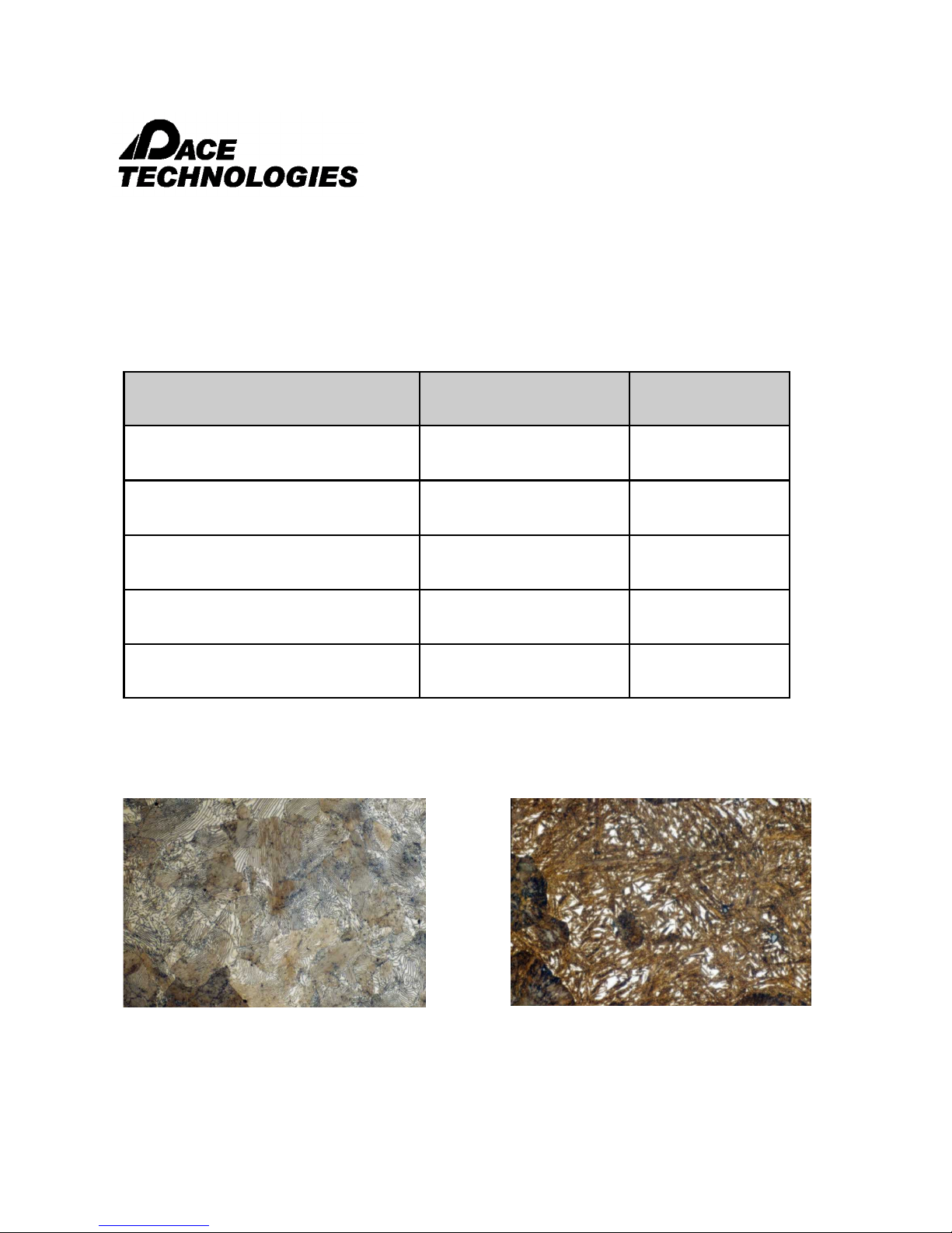
4.5.1 1095 Carbon Steel (Pearlite and Martensite Phases) Preparation of high carbon steels is
fairly straight-forward. Depending upon the heat treatment, the grinding and polishing times may
increase for the harder martensite phase.
Abrasive/surface Lubricant Time
PDGD-125M Diamond Grinding Disk water Until plane
SIRIUS Composite grinding disk 9 um DIAMAT Diamond 3 minutes
ORION Composite grinding disk 3 um DIAMAT diamond 3 minutes
1 um DIAMAT diamond on ATLANTIS pad DIALUBE Extender 2 minutes
0.05 um Nanometer alumina on MICROPAD
or TRICOTE pad
1095 Steel, Furnace-Cooled, etched with
2% nital, 400X B.F.
Microstructure: Pearlite structure
1095 Steel, Water-Quenched, etched with
picric acid, 1000X B.F.
Miicrostructure: Martensite structure
1 minute
Please read this instruction manual carefully and follow all installation, operating and safety guidelines.
14

NANO 2000T Polisher
- - - - - - - - - - - - - - - - - - - - - - - - - - - - - - - - - - - - - - - - - - - - - - - - - - ▲ INSTRUCTION MANUAL
3601 E. 34th St. Tucson, AZ 85713 USA Tel. +1 520-882-6598 Fax +1 520-882-6599 email: pace@metallographic.com Web: http://www.metallographic.com
4.5.2 Stainless Steel
Stainless steels have high concentrations of chromium (>12%) and are generally relatively soft as
compared to heat-treated steels. This makes stainless steel more susceptible to smearing.
Preparation is relatively straight-forward.
Abrasive/surface Lubricant Time
320 grit SiC paper
400 grit SiC paper
600 grit SiC paper
800 grit SiC paper
1200 grit SiC paper
1 um DIAMAT diamond on TEXPAN pad
0.05 um Nanometer alumina on NAPPAD pad
water
SIAMAT colloidal
silica
Until plane
1 minute
1 minute
1 minute
1 minute
2 minutes
1 minute
431 Stainless Steel microstructure
Please read this instruction manual carefully and follow all installation, operating and safety guidelines.
15

NANO 2000T Polisher
- - - - - - - - - - - - - - - - - - - - - - - - - - - - - - - - - - - - - - - - - - - - - - - - - - ▲ INSTRUCTION MANUAL
3601 E. 34th St. Tucson, AZ 85713 USA Tel. +1 520-882-6598 Fax +1 520-882-6599 email: pace@metallographic.com Web: http://www.metallographic.com
4.5.3 Aluminum and Aluminum Alloys
Aluminum and aluminum alloys are difficult to prepare because they are soft and contain oxide
particles which can become dislodged and scratch the surface. The key to polishing aluminum is to
use very fine polishing abrasives (fine aggregates).
Abrasive/surface Lubricant Time
P220 grit ALO paper
P500 grit ALO paper
P1200 grit ALO paper
1 um DIAMAT diamond on ATLANTIS pad DIALUBE Purple Extender 2 minutes
0.05 um Nanometer alumina on NAPPAD
pad
Water
Until plane
1 minute
1 minute
1 minute
Please read this instruction manual carefully and follow all installation, operating and safety guidelines.
Aluminum - Silicon Alloy microstructure,
Kallings etchant
16

NANO 2000T Polisher
- - - - - - - - - - - - - - - - - - - - - - - - - - - - - - - - - - - - - - - - - - - - - - - - - - ▲ INSTRUCTION MANUAL
3601 E. 34th St. Tucson, AZ 85713 USA Tel. +1 520-882-6598 Fax +1 520-882-6599 email: pace@metallographic.com Web: http://www.metallographic.com
4.5.4 Cast Iron
Cast irons are difficult materials to prepare properly because the graphite nodules (or graphite flakes)
are easily pulled out during preparation. By minimizing the sectioning damage and by starting with a
modest-grit-size SiC paper, retaining these difficult particles can be accomplished.
Abrasive/surface Lubricant Time
320 grit SiC paper
400 grit SiC paper
600 grit SiC paper
800 grit SiC paper
1200 grit SiC paper
1 um DIAMAT diamond on GOLDPAD pad
0.05 um Nanometer alumina on TRICOTE pad
water
DIALUBE Purple
Extender
Until plane
1 minute
1 minute
1 minute
1 minute
3 minutes
1 minute
Nodular Cast Iron microstructure,
Etchant 2% nital, Mag. 100X
Please read this instruction manual carefully and follow all installation, operating and safety guidelines.
Graphite Cast Iron microstructure,
Etchant 2% nital, Mag. 500X
17

NANO 2000T Polisher
- - - - - - - - - - - - - - - - - - - - - - - - - - - - - - - - - - - - - - - - - - - - - - - - - - ▲ INSTRUCTION MANUAL
3601 E. 34th St. Tucson, AZ 85713 USA Tel. +1 520-882-6598 Fax +1 520-882-6599 email: pace@metallographic.com Web: http://www.metallographic.com
4.5.5 Alumina Ceramic
The preparation of hard / brittle / porous ceramic materials is not especially difficult when a few
simple preparation tricks are known for this class of materials. First, to minimize grain pull-out (which
may be falsely characterized as porosity), sectioning damage must be minimized. This is
accomplished by sectioning with the appropriate diamond wafering blade and using the finest
practical abrasive for initial grinding.
Planar grinding is best achieved with the use of the smallest diamond abrasive possible on a metal
mesh cloth. Note that there is a trade-off between planar grinding time (abrasive size) and induced
damage. In some cases for ceramics, it is better to take more time and minimize damage at planar
grinding in order to reduce overall polishing times.
The use of SIAMAT™ colloidal silica also provides a chemical mechanical polishing (CMP) action,
which is the most effective means for eliminating both surface and subsurface damage. The
combination of SIAMAT™ colloidal silica with a DIAMAT™ polycrystalline diamond also produces
excellent surface finishes.
Abrasive/surface Lubricant Time
30 um DIAMAT diamond on CERMESH metal mesh cloth Until plane
6 um DIAMAT diamond on TEXPAN polishing pad SIAMAT colloidal silica 5 minutes
1 um DIAMAT diamond on GOLDPAD polishing pad SIAMAT colloidal silica 5 minutes
SIAMAT Colloidal silica on TEXPAN pad 5 minutes
85% Alumina microstructure, 500X
(note the sharp edges - edge retention)
Please read this instruction manual carefully and follow all installation, operating and safety guidelines.
99+% Alumina microstructure, 5000X
(thermally etched)
18

NANO 2000T Polisher
- - - - - - - - - - - - - - - - - - - - - - - - - - - - - - - - - - - - - - - - - - - - - - - - - - ▲ INSTRUCTION MANUAL
3601 E. 34th St. Tucson, AZ 85713 USA Tel. +1 520-882-6598 Fax +1 520-882-6599 email: pace@metallographic.com Web: http://www.metallographic.com
Educational Etchant and Procedure Database CD
Etchant Database - OVER 2200 ETCHANTS
Search Fields
Material or metal type
Specific alloys
Etchant name
Micro vs. Macro etchant
Keyword
MSDS for Etchant Chemicals
Preparation Guidelines
Preparation Basics
Preparation Trouble Shooting
Etchant Database Preparation Guidelines
Please read this instruction manual carefully and follow all installation, operating and safety guidelines.
19

NANO 2000T Polisher
- - - - - - - - - - - - - - - - - - - - - - - - - - - - - - - - - - - - - - - - - - - - - - - - - - ▲ INSTRUCTION MANUAL
3601 E. 34th St. Tucson, AZ 85713 USA Tel. +1 520-882-6598 Fax +1 520-882-6599 email: pace@metallographic.com Web: http://www.metallographic.com
5.0 Maintenance
5.1 Introduction
The NANO 2000T requires very minimal maintenance. However, to increase the life of the
polisher, it is suggested that the unit be rinsed after use.
5.2 Cleaning outside cabinet
The cabinet should be cleaned occasionally with a moistened cloth. Do not use any chemicals
or cleaning abrasives.
Please read this instruction manual carefully and follow all installation, operating and safety guidelines.
Easy access to electronics with
sliding rail design
20

NANO 2000T Polisher
- - - - - - - - - - - - - - - - - - - - - - - - - - - - - - - - - - - - - - - - - - - - - - - - - - ▲ INSTRUCTION MANUAL
3601 E. 34th St. Tucson, AZ 85713 USA Tel. +1 520-882-6598 Fax +1 520-882-6599 email: pace@metallographic.com Web: http://www.metallographic.com
6.0 Trouble Shooting
More extensive trouble shooting, repair guides, video’s, parts list are provided
online at www.metallographic.com or
http://www.metallographic.com/PACE-service/NANO-service.html
Problem Cause Solution
No power or
function
No air supply a. Air regulator blocked a. Clean air connections
Specimens not
polished evenly
across sample
Error Message E01 a. IPM protection produced by
Error Message E03 a. EEPROM error a. Replace board
Error Message E05 a. Over / under voltage a. Replace power supply
Error Message E06 a. Communications error a. Check for loose connector or bad cable
Error Message EOF a. Motor overheating a. Confirm proper voltage wiring set-up on
EOE a. Other errors a. Contact PACE Technologies for service
a. Unit is disconnected from main
electrical power supply
b. Main power switch is off
c. Blown fuse
A. Specimen not breaking down
grinding paper uniformly
B. Relative velocity of base and
head does not match
motor power surge
a. Verify electrical source and
connection
b. Turn on main power switch
c. Replace fuse
A. Position specimen holder so
that specimen tracks over
the entire radius of the
grinding paper
B. Match head and base speed
a. Turn polisher off and wait until LED
discharges. Turn unit back on, if problem
persist contact PACE service department
motor.
b. Reduce applied force during grinding
Pry open fuse holder
with small flat head
screwdriver
Please read this instruction manual carefully and follow all installation, operating and safety guidelines.
Replace fuse
21

NANO 2000T Polisher
- - - - - - - - - - - - - - - - - - - - - - - - - - - - - - - - - - - - - - - - - - - - - - - - - - ▲ INSTRUCTION MANUAL
3601 E. 34th St. Tucson, AZ 85713 USA Tel. +1 520-882-6598 Fax +1 520-882-6599 email: pace@metallographic.com Web: http://www.metallographic.com
7.0 Metallographic Consumables
7.1 SiC Abrasive Paper, Surface Roughness
60-grit SiC
240-grit SiC
400-grit SiC
2-dimensional line profile 3-D optical contour mapping
600-grit SiC
1200-grit SiC
Please read this instruction manual carefully and follow all installation, operating and safety guidelines.
22

NANO 2000T Polisher
- - - - - - - - - - - - - - - - - - - - - - - - - - - - - - - - - - - - - - - - - - - - - - - - - - ▲ INSTRUCTION MANUAL
3601 E. 34th St. Tucson, AZ 85713 USA Tel. +1 520-882-6598 Fax +1 520-882-6599 email: pace@metallographic.com Web: http://www.metallographic.com
7.3 Polishing Pads
Metal Mesh Cloth. This is a wire mesh material useful
for coarse and intermediate lapping / polishing. The
texture of this wire allows for the abrasive to become
semi-fixed, thus offering the advantage of increased
stock removal, while minimizing damage.
POLYPAD™ Polishing Pad. This cloth is a synthetic
polyester polishing pad which has a similar action to a
nylon pad, except that it is much more durable. It is used
in the intermediate polishing steps.
TEXPAN Polishing Pad. This is the most commonly
used polishing cloth material for the intermediate
polishing steps. TEXPAN™ Polishing pad is a lownapped cloth.
Black CHEM™ 2 Polishing Pad. This porometric
polymer pad has the consistency similar to a rubber type
of pad. Black CHEM™ 2 pad has a low nap but behaves
as an intermediate polishing pad with a performance
between low-napped and high-napped pads.
GOLDPAD Polishing Cloth. This is a woven low-
Please read this instruction manual carefully and follow all installation, operating and safety guidelines.
napped polishing pad used mostly for intermediate
diamond polishing for ceramics and metals and polymers.
ATLANTIS Polishing Cloth. This polishing pad is a
laminated polishing cloth having a resilient foam backing.
The foam backing allows the polishing to conform better
to the specimen surface.
MICROPAD™ and MICROPAD™ 2 Polishing Cloth.
This is the most commonly used high-napped final
polishing cloth for metals and polymers. Its high nap
provides a very soft and gentle polishing action.
NAPPAD™ Polishing Pad. This is another high-napped
final polishing pad useful for most metals and polymers.
It has a higher nap than MICROPAD™, providing the
most gentle polishing action of all the cloths.
23

NANO 2000T Polisher
- - - - - - - - - - - - - - - - - - - - - - - - - - - - - - - - - - - - - - - - - - - - - - - - - - ▲ INSTRUCTION MANUAL
3601 E. 34th St. Tucson, AZ 85713 USA Tel. +1 520-882-6598 Fax +1 520-882-6599 email: pace@metallographic.com Web: http://www.metallographic.com
7.4 Polycrystalline Diamond Abrasives
Polycrystalline diamond is a synthetic diamond
which provides better surface finishes and higher
removal rates than monocrystalline diamond. The
following are the advantages of a polycrystalline
diamond over a monocrystalline diamond:
Higher removal rates (self-sharpening abrasive)
Very uniform surface finish
More uniform particle size distribution
Harder / tougher particles
Blocky - shaped particles
Hexagonal (equally hard in all directions)
microcrystallites
Extremely rough surface (more cutting points)
Surface area is 300% greater than with a
monocrystalline diamond
No abrasion-resistant directionality (abrasion
independent of particle orientation)
Diamond Size (um) Color code
0.10
0.25
0.50
1.0
3.0
6.0
9.0
15
30
45
Please read this instruction manual carefully and follow all installation, operating and safety guidelines.
Charcoal
Gray
White
Blue
Green
Yellow
Red
Brown
Orange
Purple
Monocrystalline blocky - diamond
Polycrystalline multi-faceted diamond
24

NANO 2000T Polisher
- - - - - - - - - - - - - - - - - - - - - - - - - - - - - - - - - - - - - - - - - - - - - - - - - - ▲ INSTRUCTION MANUAL
3601 E. 34th St. Tucson, AZ 85713 USA Tel. +1 520-882-6598 Fax +1 520-882-6599 email: pace@metallographic.com Web: http://www.metallographic.com
7.5 Final Polishing Abrasives
Final polishing abrasives include fine diamond, alumina and colloidal silica. For successful
microstructural preparation, the polishing abrasive / cloth combination must be appropriately matched
to the specimen hardness, fracture toughness and corrosion properties of the specimen.
Colloidal Silica
Colloidal silica is a relatively soft abrasive with high chemical activity. It is an ideal chemical
mechanical polishing (CMP) abrasive. The chemical activity of colloidal silica results from the
electrochemical balance (zeta potential) required to keep very fine particles from aggregating. This
chemical balance also produces a surface phenomenon which makes the specimen surface more
chemically active. This produces a surface layer which can be mechanically removed by the colloidal
silica particles themselves, or by the mechanical scrubbing of the surface with the polishing pad.
For ceramics, the combination of fine polycrystalline diamond and colloidal silica improves surface
finishes and increases polishing rates.
Nanometer Alumina
Nanometer alumina is a polycrystalline colloidal alumina processed by a proprietary seeded gell
process. Polycrystalline alumina offers two significant improvements over conventional alumina
calcining processes:
1. Tighter, more controlled particle size distributions
2. Harder alpha alumina particles
The tighter, more controlled particle size distribution is a result of less particle aggregation which
produces significantly less scratching in soft metals, such as aluminum, tin, lead, copper and soft
steels.
Nanometer alumina is available in an acidic (pH 4) or basic (pH 10) range.
Please read this instruction manual carefully and follow all installation, operating and safety guidelines.
25

NANO 2000T Polisher
- - - - - - - - - - - - - - - - - - - - - - - - - - - - - - - - - - - - - - - - - - - - - - - - - - ▲ INSTRUCTION MANUAL
3601 E. 34th St. Tucson, AZ 85713 USA Tel. +1 520-882-6598 Fax +1 520-882-6599 email: pace@metallographic.com Web: http://www.metallographic.com
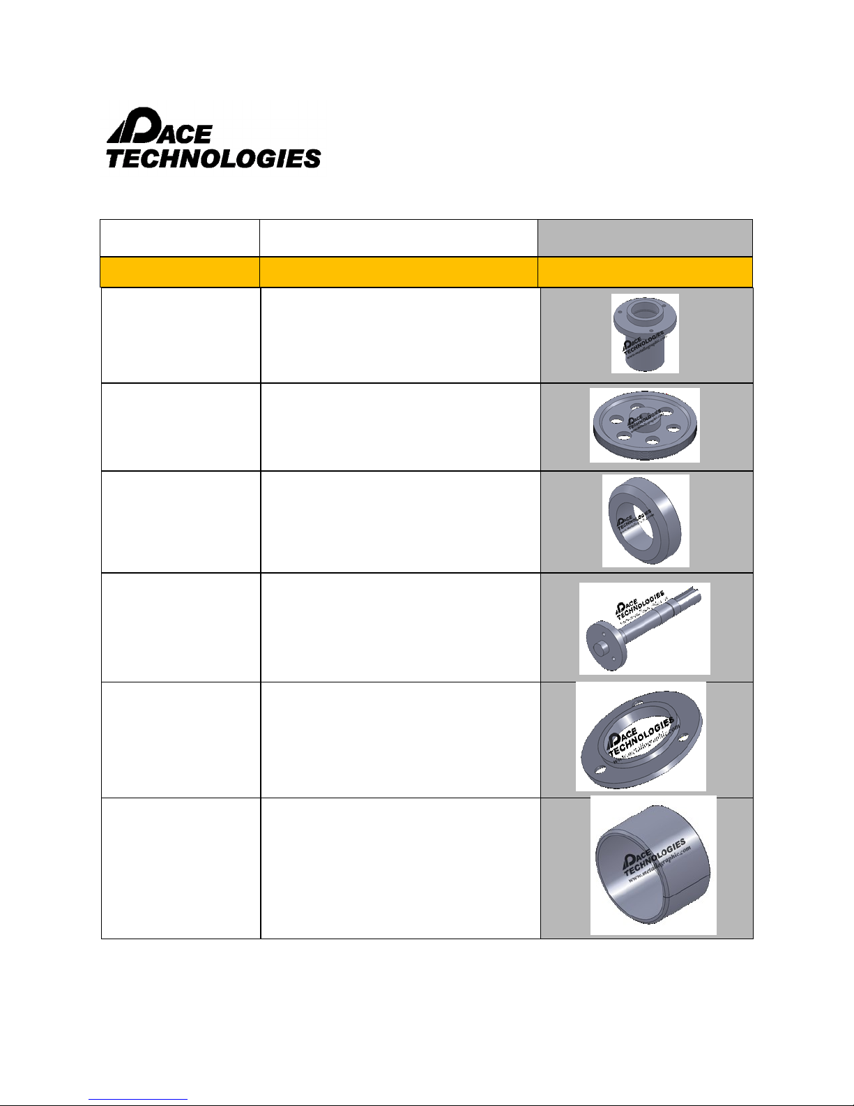
8.0 Spare Parts
Part no. Description Images
N1-007b
N1-007c
N1-008f
Electrical
NANO 1000T and 2000T Motor
(750 W - 1 hp)
NANO 1200T Motor (1.5 hp)
NANO 1000T/2000T PC board /
frequency convertor (with small cable)
N1-008f
Please read this instruction manual carefully and follow all installation, operating and safety guidelines.
NANO 1200T PC board / frequency
convertor (with small cable)
26

NANO 2000T Polisher
- - - - - - - - - - - - - - - - - - - - - - - - - - - - - - - - - - - - - - - - - - - - - - - - - - ▲ INSTRUCTION MANUAL
3601 E. 34th St. Tucson, AZ 85713 USA Tel. +1 520-882-6598 Fax +1 520-882-6599 email: pace@metallographic.com Web: http://www.metallographic.com
Part no. Description Images
N1-012b
N1-013
N1-015e
N1-015e
FUSE-C
Electrical
Transformer (24V)
Emergency Stop
Front Panel (for small cable) PC board
Front panel connection cable (small
cable)
Controller T6.3A fuse - (each)
FUSE-NA
PS-001
24RELAY
Please read this instruction manual carefully and follow all installation, operating and safety guidelines.
10 amp fuse for NANO Polishers (3/
package)
On/Off switch
24 volt relay switch
27

NANO 2000T Polisher
- - - - - - - - - - - - - - - - - - - - - - - - - - - - - - - - - - - - - - - - - - - - - - - - - - ▲ INSTRUCTION MANUAL
3601 E. 34th St. Tucson, AZ 85713 USA Tel. +1 520-882-6598 Fax +1 520-882-6599 email: pace@metallographic.com Web: http://www.metallographic.com
Part no. Description Images
RELAY-B
NANO-R
N1-009b
CORD-110V
Electrical
24 volt relay switch base
Rectifier
Solenoid Valve (24 V)
110V power cord
CORD-220R
CORD-220F
Please read this instruction manual carefully and follow all installation, operating and safety guidelines.
220V round time power cord
220V three prop flat connector
28

NANO 2000T Polisher
- - - - - - - - - - - - - - - - - - - - - - - - - - - - - - - - - - - - - - - - - - - - - - - - - - ▲ INSTRUCTION MANUAL
3601 E. 34th St. Tucson, AZ 85713 USA Tel. +1 520-882-6598 Fax +1 520-882-6599 email: pace@metallographic.com Web: http://www.metallographic.com
Part no. Description Images
PW-800
PW-1000
Mechanical Components
NANO 1000-2000 8-inch working
wheel
NANO 1000-2000 10-inch working
wheel
PW-1200 NANO 1200 12-inch working wheel
PW-1400 NANO 1200 14-inch working wheel
N1-001
N2-001
NANO 1000 Single Wheel FRP cover
NANO 2000 Double Wheel FRP cover
N12-001
N1-002
Please read this instruction manual carefully and follow all installation, operating and safety guidelines.
NANO 1200 FRP cover
NANO 1000-2000 Polishing Table
Support Platen
29

NANO 2000T Polisher
- - - - - - - - - - - - - - - - - - - - - - - - - - - - - - - - - - - - - - - - - - - - - - - - - - ▲ INSTRUCTION MANUAL
3601 E. 34th St. Tucson, AZ 85713 USA Tel. +1 520-882-6598 Fax +1 520-882-6599 email: pace@metallographic.com Web: http://www.metallographic.com
Part no. Description Images
N12-002
N1-002PEG
N1-002-O-Ring
N1-003S
Mechanical Components
NANO 1200 Polishing Table Support
Platen
Table support PEG's without o-rings
(3/set)
Table support PEG O-ring (3/pkg)
NANO 1000T/2000T Spindle assembly
N1-025
N1-003P
N1-006
Please read this instruction manual carefully and follow all installation, operating and safety guidelines.
FEMTO 1100 post collar (mounts on the
NANO 1000-2000 polisher)
NANO 1000-2000 Pulley wheel for
spindle wheel
NANO 1000-2000 Pulley for motor
30

NANO 2000T Polisher
- - - - - - - - - - - - - - - - - - - - - - - - - - - - - - - - - - - - - - - - - - - - - - - - - - ▲ INSTRUCTION MANUAL
3601 E. 34th St. Tucson, AZ 85713 USA Tel. +1 520-882-6598 Fax +1 520-882-6599 email: pace@metallographic.com Web: http://www.metallographic.com
Part no. Description Images
N1-005
N2-005
N12-005
PTM-125-005
PTM-125-006
Mechanical Components
NANO 1000T Single Wheel Belt
NANO 2000T Double Wheel Belt
NANO 1200T Single Wheel Belt
8-inch plain backed paper ring
10-inch plain backed paper ring
PTM-225-005
PTM-225-006
PTM-125-007
PTM-225-007
PTM-225-007H
Please read this instruction manual carefully and follow all installation, operating and safety guidelines.
12-inch plain backed paper ring
14-inch plain backed paper ring
8 and 10-inch polisher cover
12 and 14-inch polisher cover
Cover handle
31

NANO 2000T Polisher
- - - - - - - - - - - - - - - - - - - - - - - - - - - - - - - - - - - - - - - - - - - - - - - - - - ▲ INSTRUCTION MANUAL
3601 E. 34th St. Tucson, AZ 85713 USA Tel. +1 520-882-6598 Fax +1 520-882-6599 email: pace@metallographic.com Web: http://www.metallographic.com
Part no. Description Images
PTM-125-001
PTM-125-207
FT-004
N1-T
Mechanical Components
8 and 10-inch splash guard
12 and 14-inch splash guard
Feet (4/pkg)
NANO 1000T Template
N2-T
N12-T
N1-M-001
Please read this instruction manual carefully and follow all installation, operating and safety guidelines.
NANO 2000T Template
NANO 1200T Template
NANO 1000 Casting
32

NANO 2000T Polisher
- - - - - - - - - - - - - - - - - - - - - - - - - - - - - - - - - - - - - - - - - - - - - - - - - - ▲ INSTRUCTION MANUAL
3601 E. 34th St. Tucson, AZ 85713 USA Tel. +1 520-882-6598 Fax +1 520-882-6599 email: pace@metallographic.com Web: http://www.metallographic.com
Part no. Description Images
N2-M-001
N12-M-001
N1-M-002
N1-M-003
Mechanical Components
NANO 2000 casting
N1200 casting
Plastic cover
Femto slot holder
N1-M-004
N2-P-BC
Please read this instruction manual carefully and follow all installation, operating and safety guidelines.
NANO 1000 Bottom cover
NANO 2000 Bottom cover
33

NANO 2000T Polisher
- - - - - - - - - - - - - - - - - - - - - - - - - - - - - - - - - - - - - - - - - - - - - - - - - - ▲ INSTRUCTION MANUAL
3601 E. 34th St. Tucson, AZ 85713 USA Tel. +1 520-882-6598 Fax +1 520-882-6599 email: pace@metallographic.com Web: http://www.metallographic.com
Part no. Description Images
N12-BOT
N1-M-008
N2-M-003
N12-M-003
Mechanical Components
NANO 1200 plastic bottom cover
NANO 1000T Motor holder
NANO 2000T Motor holder
NANO 1200 Motor holder
N1-014b
N2-M-002
Please read this instruction manual carefully and follow all installation, operating and safety guidelines.
NANO 1000 rear panel
NANO 2000 rear panel
34

NANO 2000T Polisher
- - - - - - - - - - - - - - - - - - - - - - - - - - - - - - - - - - - - - - - - - - - - - - - - - - ▲ INSTRUCTION MANUAL
3601 E. 34th St. Tucson, AZ 85713 USA Tel. +1 520-882-6598 Fax +1 520-882-6599 email: pace@metallographic.com Web: http://www.metallographic.com
Part no. Description Images
N12-BP
N1-M-007
N1-M-005
Mechanical Components
NANO 1200 rear panel
Front Panel for NANO
1000T/1200T/2000T Polisher (each)
Solenoid bracket
N1-M-006
N1-M-009
Please read this instruction manual carefully and follow all installation, operating and safety guidelines.
Water adapter bracket
Water hose clamp
35
NANO 2000T Polisher
- - - - - - - - - - - - - - - - - - - - - - - - - - - - - - - - - - - - - - - - - - - - - - - - - - ▲ INSTRUCTION MANUAL
3601 E. 34th St. Tucson, AZ 85713 USA Tel. +1 520-882-6598 Fax +1 520-882-6599 email: pace@metallographic.com Web: http://www.metallographic.com
Part no. Description Images
N12-M-002
N12-M-004
N12-M-CR
N12-M-005
Mechanical Components
NANO 1200 Spindle
NANO 1200 Wheel pulley
NANO 1200 copper ring
NANO 1200 Spindle shaft
N12-M-SSA
N12-M-RSH
Please read this instruction manual carefully and follow all installation, operating and safety guidelines.
NANO 1200 Spindle shaft adapter
NANO 1200 roller shaft housing
36

NANO 2000T Polisher
- - - - - - - - - - - - - - - - - - - - - - - - - - - - - - - - - - - - - - - - - - - - - - - - - - ▲ INSTRUCTION MANUAL
3601 E. 34th St. Tucson, AZ 85713 USA Tel. +1 520-882-6598 Fax +1 520-882-6599 email: pace@metallographic.com Web: http://www.metallographic.com
Part no. Description Images
N2-009
D-REDUCER
D-ELBOW
D-NIPPLE
D-BARB
Plumbing Components
NANO 2000 Drain T-fitting
Drain Reducer
Drain elbow
Drain-nipple
Drain hose barb
P-RINSE
P-ADAPTER
PVL
PVR
Please read this instruction manual carefully and follow all installation, operating and safety guidelines.
Rinse bowl water sprayer
Rinse bowl water connector
Water value (right side) - single unit and
right side double
Water value (left side) - double unit only
38

NANO 2000T Polisher
- - - - - - - - - - - - - - - - - - - - - - - - - - - - - - - - - - - - - - - - - - - - - - - - - - ▲ INSTRUCTION MANUAL
3601 E. 34th St. Tucson, AZ 85713 USA Tel. +1 520-882-6598 Fax +1 520-882-6599 email: pace@metallographic.com Web: http://www.metallographic.com
9.0 Schematics (NANO 2000T case assembly)
Please read this instruction manual carefully and follow all installation, operating and safety guidelines.
39

NANO 2000T Polisher
- - - - - - - - - - - - - - - - - - - - - - - - - - - - - - - - - - - - - - - - - - - - - - - - - - ▲ INSTRUCTION MANUAL
3601 E. 34th St. Tucson, AZ 85713 USA Tel. +1 520-882-6598 Fax +1 520-882-6599 email: pace@metallographic.com Web: http://www.metallographic.com
9.0 Schematics (NANO 2000T case assembly)
Please read this instruction manual carefully and follow all installation, operating and safety guidelines.
40

NANO 2000T Polisher
- - - - - - - - - - - - - - - - - - - - - - - - - - - - - - - - - - - - - - - - - - - - - - - - - - ▲ INSTRUCTION MANUAL
3601 E. 34th St. Tucson, AZ 85713 USA Tel. +1 520-882-6598 Fax +1 520-882-6599 email: pace@metallographic.com Web: http://www.metallographic.com
9.1 Schematics (NANO 2000T internal mechanical assembly)
Please read this instruction manual carefully and follow all installation, operating and safety guidelines.
41

NANO 2000T Polisher
- - - - - - - - - - - - - - - - - - - - - - - - - - - - - - - - - - - - - - - - - - - - - - - - - - ▲ INSTRUCTION MANUAL
3601 E. 34th St. Tucson, AZ 85713 USA Tel. +1 520-882-6598 Fax +1 520-882-6599 email: pace@metallographic.com Web: http://www.metallographic.com
9.1 Schematics (NANO 2000T internal mechanical assembly)
Please read this instruction manual carefully and follow all installation, operating and safety guidelines.
42

NANO 2000T Polisher
- - - - - - - - - - - - - - - - - - - - - - - - - - - - - - - - - - - - - - - - - - - - - - - - - - ▲ INSTRUCTION MANUAL
3601 E. 34th St. Tucson, AZ 85713 USA Tel. +1 520-882-6598 Fax +1 520-882-6599 email: pace@metallographic.com Web: http://www.metallographic.com
9.2 Electrical Schematic (with external transformer)
Please read this instruction manual carefully and follow all installation, operating and safety guidelines.
43

NANO 2000T Polisher
- - - - - - - - - - - - - - - - - - - - - - - - - - - - - - - - - - - - - - - - - - - - - - - - - - ▲ INSTRUCTION MANUAL
3601 E. 34th St. Tucson, AZ 85713 USA Tel. +1 520-882-6598 Fax +1 520-882-6599 email: pace@metallographic.com Web: http://www.metallographic.com
9.3 Full Programming Parameters
NANO 1000T/2000T and 1200T with 20 rpm increments
(1 and 1.5 hp motor)
Note:
Do not start or run the motor before the correct input voltage is programmed;
RESET DEFAULT BEFORE REPROGRAMMING
Go to dF → Enter → -def → Enter
Steps to set converter input voltage and frequency response:
Go into Program “U” (Password:0253) → Enter → input “1001” →Enter → input “2020” → Enter →
input “3030” →Enter→ input “4170” →Display “OVER” →Enter
Go into Program “U” (Password:0253) → Enter → input “1030” →Enter → input “2170” → Enter →
input “3050” →Enter→ input “4255” →Display “OVER” →Enter
Go into Program “U” (Password:0253) → Enter → input “1050” →Enter → input “2225” → Enter →
input “3120” →Enter→ input “4255” →Display “OVER” →Enter
2. Go into Program “nS” (Password:0253) → Enter → input “2” → Enter
3. Go into Program “Sr” (Password:0253) → Enter → input “1.4” → Enter
Steps to set converter input voltage and frequency response:
FOR 110V
Go into Program “U” (Password:0253) → Enter → input “1001” →Enter → input “2025” → Enter →
input “3050” →Enter→ input “4255” →Display “OVER” →Enter
Go into Program “U” (Password:0253) → Enter → input “1050” →Enter → input “2255” → Enter →
input “3120” →Enter→ input “4255” →Display “OVER” →Enter
FOR 220V
Go into Program “U” (Password:0253) → Enter → input “1001” →Enter → input “2025” → Enter →
input “3050” →Enter→ input “4225” →Display “OVER” →Enter
Go into Program “U” (Password:0253) → Enter → input “1050” →Enter → input “2225” → Enter →
input “3120” →Enter→ input “4225” →Display “OVER” →Enter
2. Go into Program “nS” (Password:0253) → Enter → input “2” → Enter
3. Go into Program “Sr” (Password:0253) → Enter → input “1.4” → Enter
Please read this instruction manual carefully and follow all installation, operating and safety guidelines.
44

NANO 2000T Polisher
- - - - - - - - - - - - - - - - - - - - - - - - - - - - - - - - - - - - - - - - - - - - - - - - - - ▲ INSTRUCTION MANUAL
3601 E. 34th St. Tucson, AZ 85713 USA Tel. +1 520-882-6598 Fax +1 520-882-6599 email: pace@metallographic.com Web: http://www.metallographic.com
NANO 1000T/2000T and 1200T with 20 rpm increments (1 and 1.5 hp motor)
Programming Step Value Description
SR 1.4
SP1 SPEED Disc Speed - VARIABLE
T1 TIME Runtime for SP1
SP2 to SP8 200 Multiple step disk speed - DO NOT CHANGE
T2 to T8 0 Runtime for multiple steps - DO NOT CHANGE
CN 1 Number of cycles – DO NOT CHANGE
SL 100 Disc speed for SPL - preset to 100 rpm
SN 200 Disc speed for SPM - preset to 200 rpm
SH 300 Disc speed for SPH - preset to 300 rpm
DF Defaults—DO NOT CHANGE
U SET 110/220V—DO NOT CHANGE
ST 65 Shutoff motor temperature - DO NOT CHANGE
CT Current motor temperature - DO NOT CHANGE
CD1 0 Controlled by RUN/STOP button - DO NOT CHANGE
CD2 10 Display speed - DO NOT CHANGE
Belt ratio - DO NOT CHANGE
(Enter PW 0253 to access)
Please read this instruction manual carefully and follow all installation, operating and safety guidelines.
45

NANO 2000T Polisher
- - - - - - - - - - - - - - - - - - - - - - - - - - - - - - - - - - - - - - - - - - - - - - - - - - ▲ INSTRUCTION MANUAL
3601 E. 34th St. Tucson, AZ 85713 USA Tel. +1 520-882-6598 Fax +1 520-882-6599 email: pace@metallographic.com Web: http://www.metallographic.com
NANO 1000T/2000T and 1200T with 1 rpm increments (1 and 1.5 hp motor)
Note:
Do not start or run the motor before the correct input voltage is programmed;
RESET DEFAULT BEFORE REPROGRAMMING
Go to dF → Enter → -def → Enter
Steps to set converter input voltage and frequency response:
Go into Program “U” (Password:0253) → Enter → input “1001” →Enter → input “2042” → Enter
→ input “3050” →Enter→ input “4255” →Display “OVER” →Enter
Go into Program “U” (Password:0253) → Enter → input “1050” →Enter → input “2225” → Enter
→ input “3120” →Enter→ input “4255” →Display “OVER” →Enter
2. Go into Program “nS” (Password:0253) → Enter → input “2” → Enter
3. Go into Program “Sr” (Password:0253) → Enter → input “1.4” → Enter
NOTE: If any of the numbers are entered incorrectly in the above sequence, the process
requires that the default be reset and the program the sequence entered again until it is
exactly correct. THIS IS VERY CRITICAL OTHER WISE AN E01 ERROR CAN OCCUR.
Steps to set converter input voltage and frequency response:
The above settings are for maximum torque which will result is a slight vibration between 240280 rpm, to reduce the vibration at the slight loose of torque rest these parameters:
Go into Program “U” (Password:0253) → Enter → input “1001” →Enter → input “2040” → Enter
→ input “3011” →Enter→ input “4050” →Display “OVER” →Enter
Go into Program “U” (Password:0253) → Enter → input “1011” →Enter → input “2050” → Enter
→ input “3014” →Enter→ input “4050” →Display “OVER” →Enter
Go into Program “U” (Password:0253) → Enter → input “1014” →Enter → input “2050” → Enter
→ input “3050” →Enter→ input “4225” →Display “OVER” →Enter
2. Go into Program “nS” (Password:0253) → Enter → input “2” → Enter
3. Go into Program “Sr” (Password:0253) → Enter → input “1.4” → Enter
Please read this instruction manual carefully and follow all installation, operating and safety guidelines.
46

NANO 2000T Polisher
- - - - - - - - - - - - - - - - - - - - - - - - - - - - - - - - - - - - - - - - - - - - - - - - - - ▲ INSTRUCTION MANUAL
3601 E. 34th St. Tucson, AZ 85713 USA Tel. +1 520-882-6598 Fax +1 520-882-6599 email: pace@metallographic.com Web: http://www.metallographic.com
NANO 1000T/2000T and 1200T with 1 rpm increments (1 and 1.5 hp motor)
Programming Step Value Description
SP1 SPEED Disc Speed - VARIABLE
T1 TIME Runtime for SP1
SP2 to SP8 200 Multiple step disk speed - DO NOT CHANGE
T2 to T8 0 Runtime for multiple steps - DO NOT CHANGE
Cn 1 Number of cycles – DO NOT CHANGE
SL 100 Disc speed for SPL - preset to 100 rpm
SN 200 Disc speed for SPM - preset to 200 rpm
SH 300 Disc speed for SPH - preset to 300 rpm
DF Defaults—DO NOT CHANGE
U SET 110/220V—DO NOT CHANGE
ST 65 Shutoff motor temperature - DO NOT CHANGE
CT Current motor temperature - DO NOT CHANGE
Controlled by RUN/STOP button - DO NOT CHANGE
CD1 0
CD2 10
CD3
CD4 1000 Max. speed (rpm)
CD5 100 Min. speed (rpm) (do not go below 100 rpm)
CD6 15 Carrier wave value – DO NOT CHANGE
0: Front board control
1: External control of board
Display speed - DO NOT CHANGE
10: Displays speed (rpm)
11: Displays frequency (Hz)
Motor control method – DO NOT CHANGE
Please read this instruction manual carefully and follow all installation, operating and safety guidelines.
47
 Loading...