

NANO 1000T / FEMTO 1500
Polishing Head
- - - - - - - - - - - - - - - - - - - - - - - - - - - - - - - - - - - - - - - - - - - - - - - - - - ▲ INSTRUCTION MANUAL
3601 E. 34th St. Tucson, AZ 85713 USA Tel. +1 520-882-6598 Fax +1 520-882-6599 email: pace@metallographic.com Web: http://www.metallographic.com
Equipment Type: Semi-automated polishing head
Model:
Electrical
Requirements:
Frequency: 50/60 Hz
Motor Horsepower: 120W
Manual Revision
Date:
Please read this instruction manual carefully and follow all installation, operating and safety guidelines.
NANO 1000T / FEMTO 1500
110 / 220 Volts (single-phase)
February 14, 2019
1

NANO 1000T / FEMTO 1500
Polishing Head
- - - - - - - - - - - - - - - - - - - - - - - - - - - - - - - - - - - - - - - - - - - - - - - - - - ▲ INSTRUCTION MANUAL
3601 E. 34th St. Tucson, AZ 85713 USA Tel. +1 520-882-6598 Fax +1 520-882-6599 email: pace@metallographic.com Web: http://www.metallographic.com
Contents
PAGE
Warranty
1.0 Product Description
2.0 Unpacking, Shipping and Installation
3.0 Installation
4.0 Safety
5.0 Start up
6.0 Maintenance
7.0 Trouble Shooting
ii
1
5
6
17
19
47
48
8.0 Metallographic Consumables
9.0 Spare Parts
10.0 Schematics
Please read this instruction manual carefully and follow all installation, operating and safety guidelines.
49
56
79
i
2

NANO 1000T / FEMTO 1500
Polishing Head
- - - - - - - - - - - - - - - - - - - - - - - - - - - - - - - - - - - - - - - - - - - - - - - - - - ▲ INSTRUCTION MANUAL
3601 E. 34th St. Tucson, AZ 85713 USA Tel. +1 520-882-6598 Fax +1 520-882-6599 email: pace@metallographic.com Web: http://www.metallographic.com
WARRANTY
Terms and Conditions applying to all PACE Technologies Products
1. LIMITED WARRANTY AND DISCLAIMER:
PACE Technologies Products are warranted for one year from the purchase date to be free from defects in
material and workmanship under correct use, normal operating conditions, and proper application. PACE
Technologies obligation under this warranty shall be limited to the repair or exchange, at PACE
Technologies option, of any PACE Technologies Product or part which proves to be defective as provided
herein. PACE Technologies reserves the right to either inspect the product at Buyer’s location or require it
to be returned to the factory for inspection. Buyer is responsible for freight to and from factory on all
warranty claims. The above warranty does not extend to goods damaged or subjected to accident, abuse or
misuse after release from PACE Technologies warehouse, nor goods altered or repaired by anyone other
than specifically authorized PACE Technologies representatives. PACE Technologies shall not in any way
be responsible for the consequences of any alteration, modification or misuse unless previously approved in
writing by an officer of PACE Technologies.
PACE TECHNOLOGIES MAKES NO EXPRESS WARRANTIES OTHER THAN THOSE WHICH ARE
SPECIFICALLY DESCRIBED HEREIN. Any description of the goods sold hereunder, including any
reference to Buyer’s specifications and any description in catalogs, circulars and other written material
published by PACE Technologies, is the sole purpose of identifying such goods and shall not create an
express warranty that the goods shall conform to such description.
THIS WARRANTY IS EXPRESSLY IN LIEU OF ALL OTHER WARRANTIES, EXPRESSED OR
IMPLIED. THERE ARE NO IMPLIED WARRANTIES OF MERCHANT ABILITY OR FITNESS FOR
PARTICULAR PURPOSE. THIS WARRANTY STATES PACE TECHNOLOGIES ENTIRE AND
EXCLUSIVE LIABILITY AND BUYER’S EXCLUSIVE REMEDY FOR ANY CLAIM FOR DAMAGES
IN CONNECTIONS WITH PACE TECHNOLOGIES PRODUCTS. PACE TECHNOLOGIES WILL IN
NO EVENT BE LIABLE FOR INCIDENTAL OR CONSEQUENTIAL DAMAGES WHATSOEVER,
NOR FOR ANY SUM IN EXCESS OF THE PURCHASE PRICE.
2. LIABILITY CAP:
PACE Technologies maximum aggregate liability for loss and damage arising under, resulting from or in
connection with the supply or use of the Equipment and Consumables provided under this purchase, or from
the performance or breach of any obligation (s) imposed hereunder, whether such liability arises from any
one or more claims or actions for breach of contract, tort, (including negligence), delayed completion,
warranty, indemnity, strict liability or otherwise, unless otherwise limited by the terms hereof, shall be
limited to one hundred percent (100%) of the purchase price.
3. DELIVERY:
Customer assumes and shall bear the risk of all loss or damage to the Products from every cause whatsoever,
whether or not insured, and title to such Products shall pass to Customer upon PACE Technologies delivery
of the Products to the common carrier of Pace Technologies choice, or the carrier specified in writing by
Customer, for shipment to Customer. Any claims for breakage, loss, delay, or damage shall be made to the
carrier by the Customer and Pace Technologies will render customer reasonable assistance in prosecuting
such claims.
Please read this instruction manual carefully and follow all installation, operating and safety guidelines.
ii
3

NANO 1000T / FEMTO 1500
Polishing Head
- - - - - - - - - - - - - - - - - - - - - - - - - - - - - - - - - - - - - - - - - - - - - - - - - - ▲ INSTRUCTION MANUAL
3601 E. 34th St. Tucson, AZ 85713 USA Tel. +1 520-882-6598 Fax +1 520-882-6599 email: pace@metallographic.com Web: http://www.metallographic.com
4. ACCEPTANCE:
Customer shall inspect the Products promptly upon receipt of delivery. Unless customer objects in
writing within thirty (30) business days thereafter, customer shall be deemed to have accepted the
Products. All claims for damages, errors, or shortage in Products delivered shall be made by Customer
in writing within such five (5) business day period. Failure to make any claim timely shall constitute
acceptance of the Products.
5. PAYMENT:
Customer agrees to provide timely payment for the Products in accordance with the terms of payment
set forth on the reverse side hereof or in any proposal submitted herewith. If any payment is not paid
on or before its due date, Customer shall pay interest on such late payment from the due date until paid
at the lesser of 12% per annum or the maximum rate allowed by law.
6. DEFAULT:
If Buyer is in default (including, but not limited to, the failure by Buyer to pay all amounts due and
payable to Seller) under the work or purchase order or any other agreement between Buyer and Seller,
Buyer’s rights under the warranty shall be suspended during any period of such default and the original
warranty period will not be extended beyond its original expiration date despite such suspension of
warranty rights.
7. MISCELLANEOUS PROVISIONS:
This agreement has been made in and shall be governed by the laws of the State of Arizona. These
terms and conditions and the description of the Products on the reverse side hereof or in any proposal
submitted herewith constitute the entire agreement and understanding of the parties with respect to this
sale and supersede all prior and contemporaneous agreements or understandings, inducements or
representations, expressed or implied, written or oral, between the parties with respect hereto. Any
term or provision of this Agreement may be amended, and any observance of any term of this
Agreement may be waived, only by a writing signed by the party to be bounds. The waiver by a party
of any breach shall not be deemed to constitute a waiver of any other breach. Should suit be brought on
this Agreement, the prevailing party shall be entitled to recover its reasonable attorneys’ fees and other
costs of suit including costs and attorneys’ fees incurred on appeal or in collection of any judgment.
Please read this instruction manual carefully and follow all installation, operating and safety guidelines.
iii
4
NANO 1000T / FEMTO 1500
Polishing Head
- - - - - - - - - - - - - - - - - - - - - - - - - - - - - - - - - - - - - - - - - - - - - - - - - - ▲ INSTRUCTION MANUAL
3601 E. 34th St. Tucson, AZ 85713 USA Tel. +1 520-882-6598 Fax +1 520-882-6599 email: pace@metallographic.com Web: http://www.metallographic.com
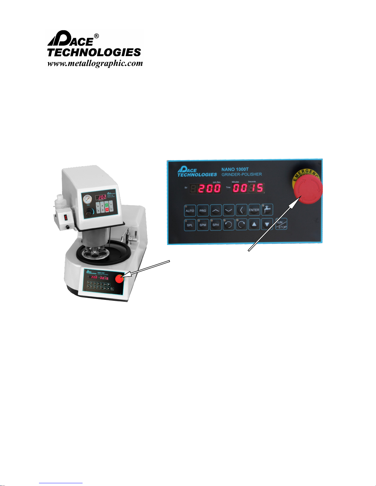
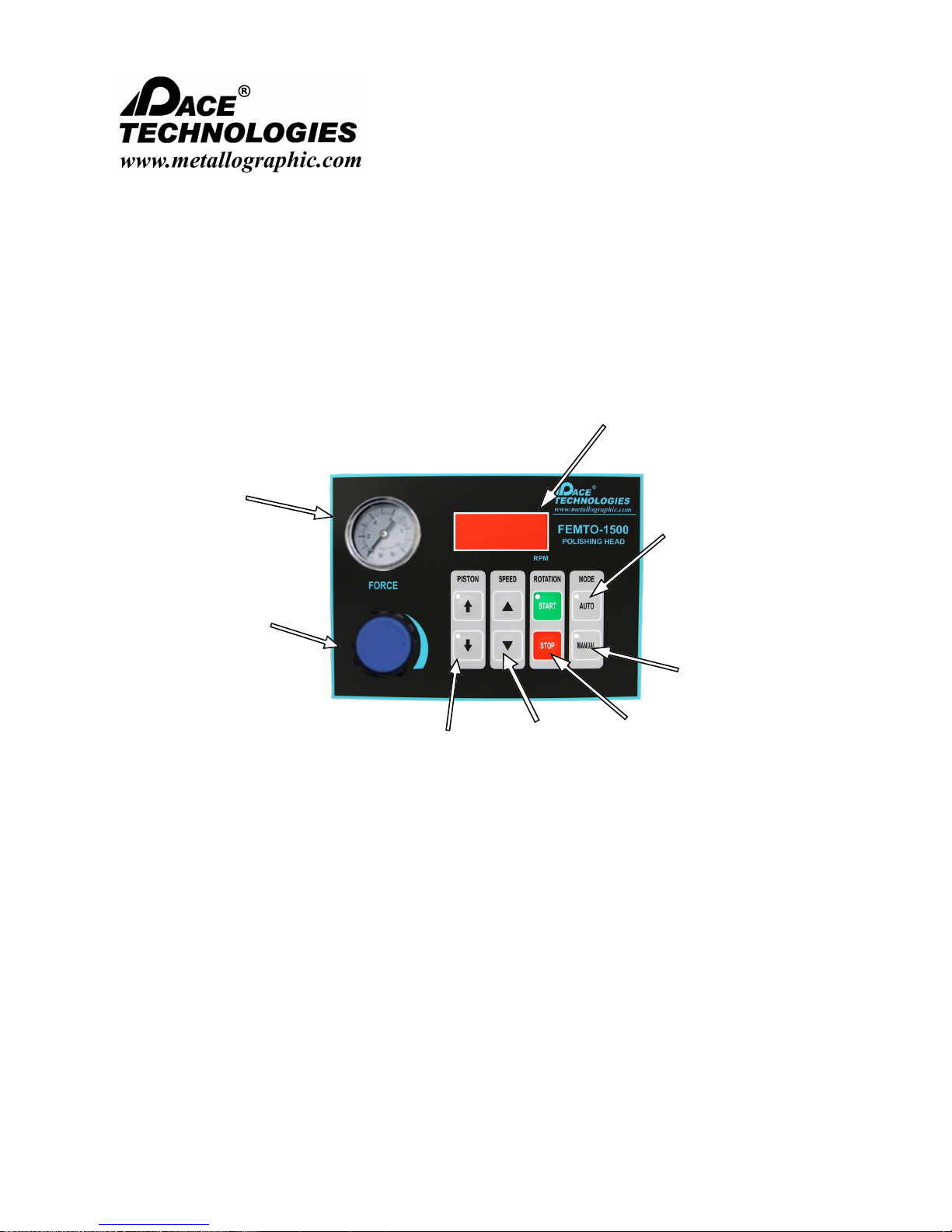
1.0 Product Description
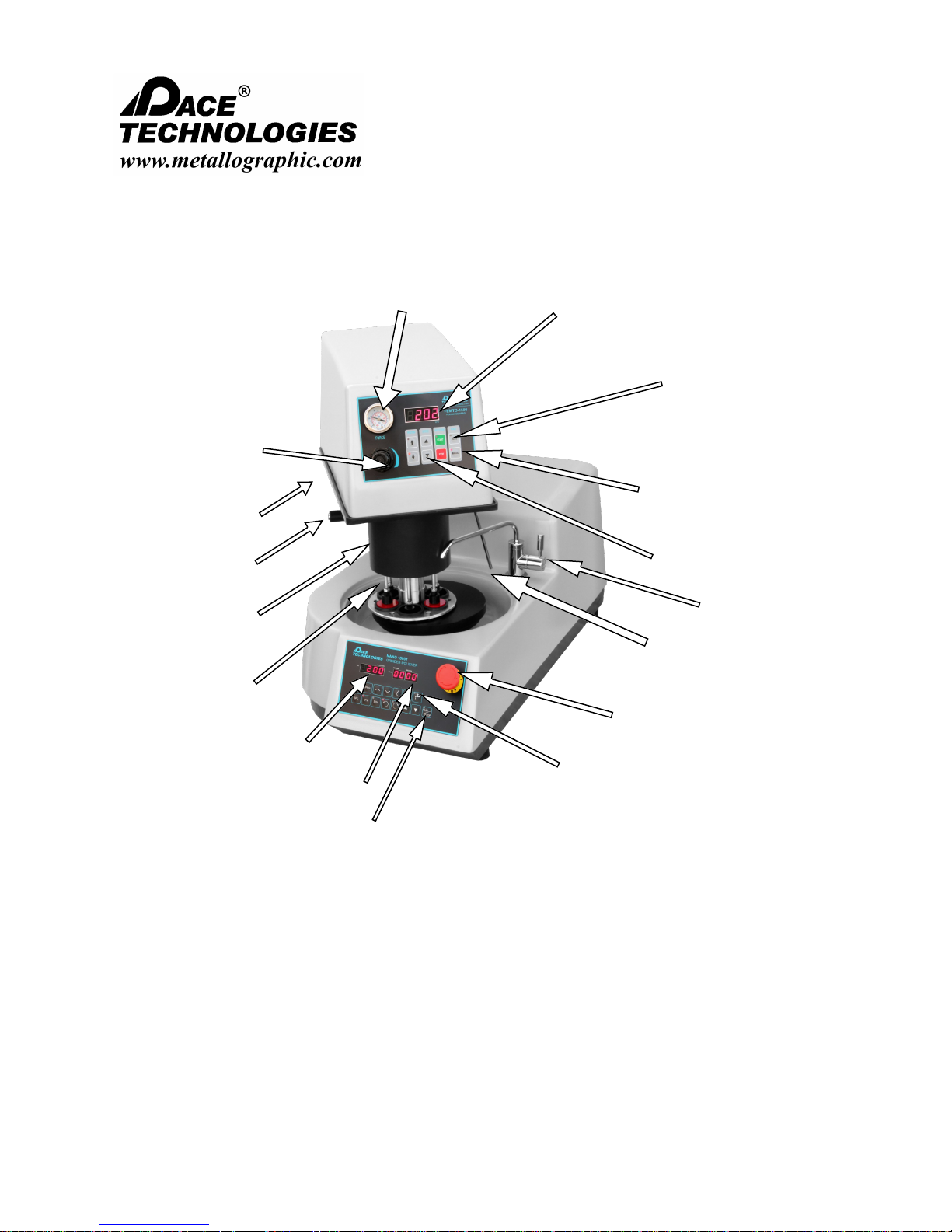
1.1 General Description
Pressure
Adjustment
Dispenser ON/OFF
Dispenser
controller
Head release
lever / switch
Specimen
Pressure pistons
Pressure Gauge
Variable speed
display
Manual Start/Stop
AUTO/MANUAL
mode buttons
Pistons
UP/DOWN
Water Supply
Dispenser feed
Emergency
Stop button
Speed display
Timer display
Auto start button
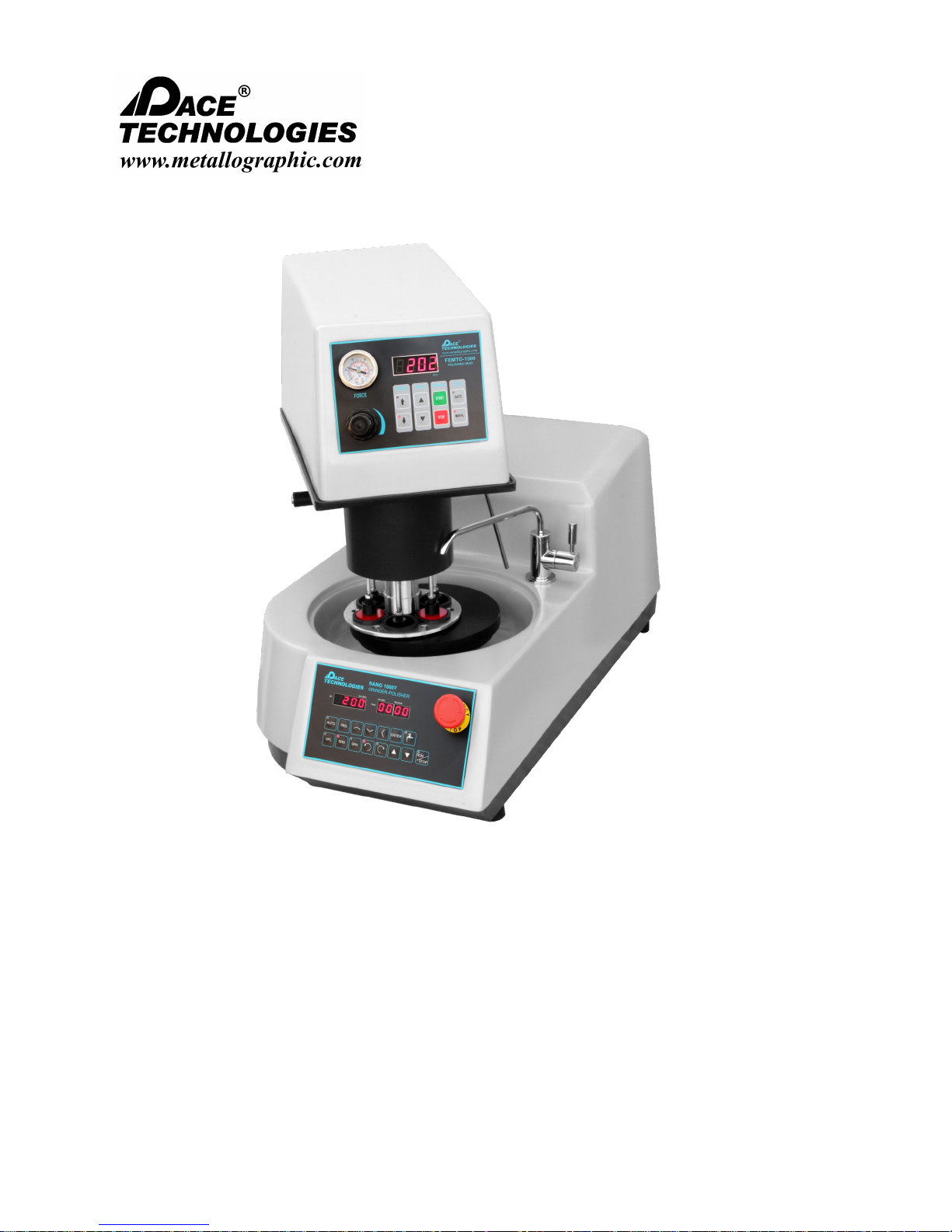
The FEMTO 1500 is a variable speed polishing head (0-200 rpm) for use with the NANO 1000T
or NANO 2000T grinding/ polishing machine for semi-automated metallographic specimen
preparation. The FEMTO 1500 can also run either automatically with the NANO polishing base
or in a manual mode independently control from the NANO polisher.
Please read this instruction manual carefully and follow all installation, operating and safety guidelines.
Water
solenoid
switch
1

NANO 1000T / FEMTO 1500
Polishing Head
- - - - - - - - - - - - - - - - - - - - - - - - - - - - - - - - - - - - - - - - - - - - - - - - - - ▲ INSTRUCTION MANUAL
3601 E. 34th St. Tucson, AZ 85713 USA Tel. +1 520-882-6598 Fax +1 520-882-6599 email: pace@metallographic.com Web: http://www.metallographic.com
1.2 Technical Specifications
Electrical specifications: 110 / 220V single-phase
(50/60 Hz)
Number of specimens: Individual Force:
1-6 samples (1-inch to 1.5-inch
diameter.
1-3 samples 2-inch diameter
(holder and rings sold separately)
Force application: Individual piston
Motor power: 120 W
Polishing head speed:
Weight: Approx. 55 lbs (25 kg)
Dimensions (WxHxD): Approx. 13” x 18” x 18”
Working temperature: 32° - 100°F (0 - 40°C)
Shipping temperature: 32° - 100°F (0 - 40°C)
Storage temperature: 32° - 100°F (0 - 40°C)
Hook ups: Air - clean filter air with lubricator
EU Directives: Machinery Directive 2006/42/EC
Low Voltage Directive 2006/95/EC
Electromagnetic Compatibility Directive 2004/108/EC
EU Harmonized Standards: EN ISO 1200:2010
EN 61010-1:2010
EN 61326-1:2006
0 to 200 rpm variable speed
(330 mm x 450 mm x 450 mm)
(recommended)
Electrical - 110V or 220V, 50/60
Hz)
Please read this instruction manual carefully and follow all installation, operating and safety guidelines.
2
NANO 1000T / FEMTO 1500
Polishing Head
- - - - - - - - - - - - - - - - - - - - - - - - - - - - - - - - - - - - - - - - - - - - - - - - - - ▲ INSTRUCTION MANUAL
3601 E. 34th St. Tucson, AZ 85713 USA Tel. +1 520-882-6598 Fax +1 520-882-6599 email: pace@metallographic.com Web: http://www.metallographic.com
1.3 Features and Benefits
The FEMTO 1500 is equipped with a 120 W
variable 0-200 rpm speed motor. The drive
mechanism is connected to the motor via a
maintenance-free anti-slip polychain.
The FEMTO 1500 also has a lubricant
dispenser in addition to a high flow water
valve for hands free wet grinding with
abrasive papers and lubrication for polishing.
In addition, the FEMTO 1500 can be operated
either automatically or independently with the
NANO polishing base.
Note: Installation of the FEMTO 1500 /
NANO polishing base should be on a flat
sturdy surface, with easy access to drain,
water and electrical connections.
Please read this instruction manual carefully and follow all installation, operating and safety guidelines.
3

NANO 1000T / FEMTO 1500
Polishing Head
- - - - - - - - - - - - - - - - - - - - - - - - - - - - - - - - - - - - - - - - - - - - - - - - - - ▲ INSTRUCTION MANUAL
3601 E. 34th St. Tucson, AZ 85713 USA Tel. +1 520-882-6598 Fax +1 520-882-6599 email: pace@metallographic.com Web: http://www.metallographic.com
1.4 Single Force vs. Central Force Comparison
Single Force vs. Central Force Polishing Machines
Metallographic semi-automated polishing machines are available with
individual/ single specimen loading or with a fixed central holder. The
main advantage for using a central force holder is that the overall
specimen flatness is better. The primary advantages for individual
specimen holders are fewer required grinding/ polishing steps and
the ability to re-polish samples without the need to re-planarize the
Central Force: The individual pistons apply the
polishing force to the landing pads and pushes
down the holder through the spring loaded
central male coupler. For central polishing a
minimum of three samples locked into the holder
is required; however, flatness is then fixed over
all the mounted specimens
Note: With independent pistons, initial grinding can be done with finer abrasives, thus reducing the
number of grinding steps. For flatter specimen preparation a central force polishing system (FEMTO
1500 or FEMTO 2500) are recommended.
Please read this instruction manual carefully and follow all installation, operating and safety guidelines.
Individual Force: Individual specimen force can
be applied using the Quick Release Chuck system
by screwing down the outside of the coupler so as
to lock the specimen mounting plate into a rigid
plane. This set-up allows for the individual holder
to be removed and cleaned. This holder also
eliminates the need to re-plane the samples if they
4

NANO 1000T / FEMTO 1500
Polishing Head
- - - - - - - - - - - - - - - - - - - - - - - - - - - - - - - - - - - - - - - - - - - - - - - - - - ▲ INSTRUCTION MANUAL
3601 E. 34th St. Tucson, AZ 85713 USA Tel. +1 520-882-6598 Fax +1 520-882-6599 email: pace@metallographic.com Web: http://www.metallographic.com
2.0 Unpacking, Shipping and Installation
2.1 Unpacking
2.2 Shipping
Unit is delivered in a box. Unpack and check for completeness of
parts.
Measures WxHxD: 20” x 30” x 37” (with NANO 1000T).
Weight: Varies, depending upon model
(approximately 55 lbs—FEMTO head).
When moving box, lift from bottom.
! Caution: Heavy sensitive electronic equipment. Take care to
avoid bodily injury and damage to the unit.
Please read this instruction manual carefully and follow all installation, operating and safety guidelines.
5

NANO 1000T / FEMTO 1500
Polishing Head
- - - - - - - - - - - - - - - - - - - - - - - - - - - - - - - - - - - - - - - - - - - - - - - - - - ▲ INSTRUCTION MANUAL
3601 E. 34th St. Tucson, AZ 85713 USA Tel. +1 520-882-6598 Fax +1 520-882-6599 email: pace@metallographic.com Web: http://www.metallographic.com
3.0 Installation
Install unit carefully! Improper installation voids warranty.
!
The FEMTO 1500 / NANO 1000T polishing base should be placed on a flat stable
surface.
Requires air, water supply, drain and electrical connections.
After mounting on NANO polishing base (water, drain, electrical) and connection to an
air and electrical supply, the system is ready for operation by activating the main power
switches on both the NANO polisher and FEMTO head for Automatic operation.
NANO interface
cable
Head release
lever
Post locking
collar
Head release
switch
FEMTO post
Lubricant
Dispenser
Dispenser
Interface
Cable
Please read this instruction manual carefully and follow all installation, operating and safety guidelines.
6

NANO 1000T / FEMTO 1500
Polishing Head
- - - - - - - - - - - - - - - - - - - - - - - - - - - - - - - - - - - - - - - - - - - - - - - - - - ▲ INSTRUCTION MANUAL
3601 E. 34th St. Tucson, AZ 85713 USA Tel. +1 520-882-6598 Fax +1 520-882-6599 email: pace@metallographic.com Web: http://www.metallographic.com
Installation (continued)
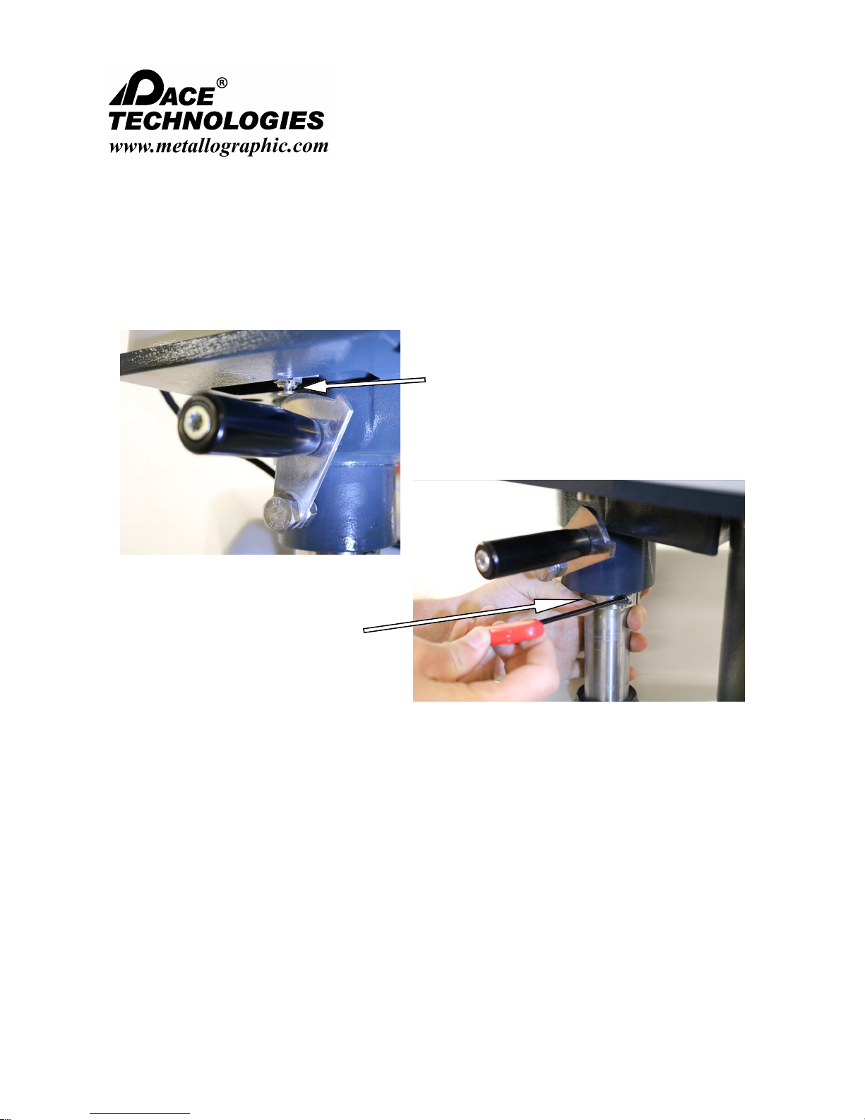
Post
3.1 Post Connection
Bottom side post
location on
NANO polisher
positioning
Plate Groove
Post slot
Post
connection:
Loosen and swing the Plat Groove for the post so that you can see the post
Remove plastic cover from the top of the NANO polisher and lower the FEMTO post
IMPT: Securing the post is very important and must be done by tightening the bolt/
Remove the plastic cover plate from underneath the NANO polisher.
alignment notch. The post notch must fit into the groove in the brass plate.
into the hole. (note it is recommended to tighten the FEMTO post locking lever first).
Work the post down as far as possible.
The post notch should extend below the NANO casting base. If the post does not
go down all the way align the post with the plate groove and insert bolt/flat washer
and locking washer and tighten so that the post is fully down.
Replace plate and NANO plastic cover.
washer/locker washer from underneath the NANO polisher
Please read this instruction manual carefully and follow all installation, operating and safety guidelines.
7

NANO 1000T / FEMTO 1500
Polishing Head
- - - - - - - - - - - - - - - - - - - - - - - - - - - - - - - - - - - - - - - - - - - - - - - - - - ▲ INSTRUCTION MANUAL
3601 E. 34th St. Tucson, AZ 85713 USA Tel. +1 520-882-6598 Fax +1 520-882-6599 email: pace@metallographic.com Web: http://www.metallographic.com
Installation (continued)
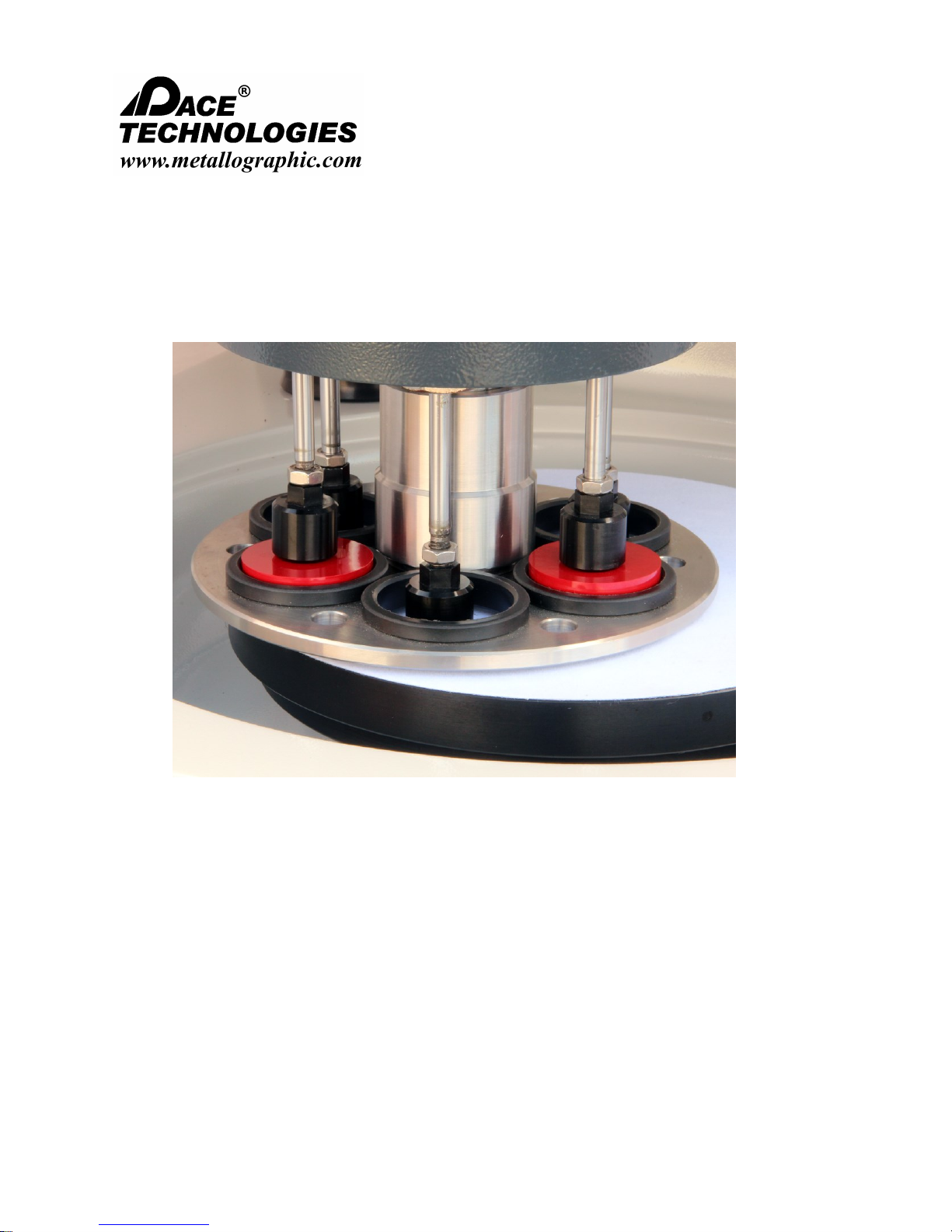
3.2 Quick Release Chuck Installation
The Quick Release Chuck is a system developed specifically for use in
the FEMTO 1500 polishing head. This systems purpose is to create a
fast and easy way of changing between our Central and Individual force
sample holders. With the Quick Release Chuck installed one polishing
head can be used to process and prepare samples with differing force
requirements. It is also possible to utilize both Individual and Central
force holders in the single procedure.
3.3 Installing a Central Force Sample Holder
To install the Central force sample holder simply
move the FEMTO head to the left of the NANO
bowl and lift the Quick Release Chuck sleeve
up. Now with your other hand push the “dogbone” male connector, on the sample holder, up
into the chuck until a click is heard. Push the
sleeve down then tighten the thump screw.
Tighten until a little bit of resistance is felt. The
Central force holder is ready to be used. Once
the procedure is completed, lift the sleeve back
up and pop off the sample holder to inspect the
samples. This system allows the sample holder
to be reinserted as many times as need
throughout the procedure.
Central Force Holder Part Number
1-inch / 25 mm central specimen holder (3-6 samples) QRC-SH100A-1500
1.25-inch / 30 mm central specimen holder (3-6 samples) QRC-SH125A-1500
1.5-inch / 40 mm central specimen holder (3-6 samples) QRC-SH150A-1500
2-inch / 50 mm central specimen holder (3 samples) QRC-SH200A-1500
Please read this instruction manual carefully and follow all installation, operating and safety guidelines.
Central Force Loading plate CF-LP-1500
8

NANO 1000T / FEMTO 1500
Polishing Head
- - - - - - - - - - - - - - - - - - - - - - - - - - - - - - - - - - - - - - - - - - - - - - - - - - ▲ INSTRUCTION MANUAL
3601 E. 34th St. Tucson, AZ 85713 USA Tel. +1 520-882-6598 Fax +1 520-882-6599 email: pace@metallographic.com Web: http://www.metallographic.com
Installation (continued)
3.4 Installing Samples in Central Force Holder
Step 1: The loading plate is used to
mount samples into the Central
Force holder.
Step 3: Place samples into the holder as
shown below. The Central force
holder can hold either three or six
samples during a procedure.
Step 2: Place the Central Force holder onto the loading
plate as shown below. Make sure the sample
holder is flat against the rim of the Loading
Plate.
Step 4: Push each sample down using a thumb
and secure the setscrew located on the
edge of the sample holder. Do this for
each loaded sample.
Step 5: Remove the sample holder from the loading plate. It is now ready to be installed in
the Quick Release Chuck.
Please read this instruction manual carefully and follow all installation, operating and safety guidelines.
9

NANO 1000T / FEMTO 1500
Polishing Head
- - - - - - - - - - - - - - - - - - - - - - - - - - - - - - - - - - - - - - - - - - - - - - - - - - ▲ INSTRUCTION MANUAL
3601 E. 34th St. Tucson, AZ 85713 USA Tel. +1 520-882-6598 Fax +1 520-882-6599 email: pace@metallographic.com Web: http://www.metallographic.com
Installation (continued)
3.5 Installing Individual Force Sample Holder
To install the Individual force holder move the FEMTO
head to the side of the NANO polisher. Lift the sleeve of
the Quick Release Chuck and push the sample holder
up into the chuck. Push the sleeve back down. Next,
turn the sleeve and thread the screw onto the holder.
This thread is reverse threaded. Therefore the normal
method of “lefty loose, righty tight” is not applicable here.
Instead it is “lefty tight, righty loose.” Once the sleeve is
secured around the threads turn the thumb screw on the
chuck. This greatly reduces the risk of the holder getting
loose during operation. Once finished with the Individual
force holder, simply unscrew the chuck from the sample
holder and then left the sleeve up again. The sample
holder is now able to be removed.
Specimen Holder FEMTO 1500
Single specimen holder mounting fixture for FEMTO 1100/1500, requires one set
of 3 plastic rings ranging from 1-inch up to 1.5-inch or 25mm up to 40 mm
(ordered separately)
1-in diameter rings SR-0100
1.25-in diameter rings SR-0125
1.5-in diameter rings SR-0150
25 mm diameter rings SR-25mm
30mm diameter rings SR-30mm
40 mm diameter rings SR-40mm
2-inch single specimen holder mounting fixture for FEMTO 1100/1500, requires
one set of 3, 2-inch or 50 mm plastic rings (ordered separately)
2-in diameter specimen rings SR-0200
50 mm diameter specimen rings SR-50mm
Individual specimen holder mounting fixture (for use with glass slide holders) SH-GHOLDER-1500
Glass slide holder for 27 x 47 mm and 1 x 3-inch slides (each) SR-G
SH-1150
SH-1250
Please read this instruction manual carefully and follow all installation, operating and safety guidelines.
10

NANO 1000T / FEMTO 1500
Polishing Head
- - - - - - - - - - - - - - - - - - - - - - - - - - - - - - - - - - - - - - - - - - - - - - - - - - ▲ INSTRUCTION MANUAL
3601 E. 34th St. Tucson, AZ 85713 USA Tel. +1 520-882-6598 Fax +1 520-882-6599 email: pace@metallographic.com Web: http://www.metallographic.com
Installation (continued)
3.6 Height Adjustment for FEMTO Head /Specimen Holder
Step 1: To lift the
FEMTO head, rotate
the lever to engage
the piston
Step 2: Lower the
FEMTO head onto a
Step 3: Loosen and
lower post the
holding collar
Specimen
holder height
adjustment:
Step 2: Place the working wheel with the highest profile abrasive/polishing pad
The specimen holder height needs to be adjusted to prevent the pistons from
grinding during the operation of the machine.
Step 1: Connect air and lift up head.
on the wheel. Using a single wall box as a spacer, place the cardboard on top of
the working wheel/abrasive combination.
Step 3: Loosen holding ring collar on the FEMTO post and slide down out of the
way.
cardboard spacer
Please read this instruction manual carefully and follow all installation, operating and safety guidelines.
11
NANO 1000T / FEMTO 1500
Polishing Head
- - - - - - - - - - - - - - - - - - - - - - - - - - - - - - - - - - - - - - - - - - - - - - - - - - ▲ INSTRUCTION MANUAL
3601 E. 34th St. Tucson, AZ 85713 USA Tel. +1 520-882-6598 Fax +1 520-882-6599 email: pace@metallographic.com Web: http://www.metallographic.com
Installation (continued)
3.7 Height Adjustment for FEMTO Head /Specimen Holder (continued)
Step 4: Rotate the
release lever to
disengage piston
button
Specimen
holder height
adjustment:
Step 5. Slide the
holding ring collar
up to the bottom of
the FEMTO head
and tighten.
Step 4. Rotate release lever slightly to lower the head.
Step 5. Slide the holding ring collar up to the bottom of the FEMTO head
and tighten.
Step 6. Lift head by rotating release lever to engage piston button on
bottom of FEMTO head. Remove cardboard spacer and lower the FEMTO
head.
Please read this instruction manual carefully and follow all installation, operating and safety guidelines.
12
NANO 1000T / FEMTO 1500
Polishing Head
- - - - - - - - - - - - - - - - - - - - - - - - - - - - - - - - - - - - - - - - - - - - - - - - - - ▲ INSTRUCTION MANUAL
3601 E. 34th St. Tucson, AZ 85713 USA Tel. +1 520-882-6598 Fax +1 520-882-6599 email: pace@metallographic.com Web: http://www.metallographic.com
Installation (continued)
.8 Height Adjustment for FEMTO Head /Specimen Holder (continued)
Specimen
holder height
adjustment:
Please read this instruction manual carefully and follow all installation, operating and safety guidelines.
Step 7. In the FEMTO manual mode, lower pistons with the down button.
Verify that the bottom of the piston is not rubbing against the abrasive
surface. (Note it is better to operate the specimen holder as close to the
working abrasive wheel as possible in order to get flatter specimens
13
NANO 1000T / FEMTO 1500
Polishing Head
- - - - - - - - - - - - - - - - - - - - - - - - - - - - - - - - - - - - - - - - - - - - - - - - - - ▲ INSTRUCTION MANUAL
3601 E. 34th St. Tucson, AZ 85713 USA Tel. +1 520-882-6598 Fax +1 520-882-6599 email: pace@metallographic.com Web: http://www.metallographic.com
Installation (continued)
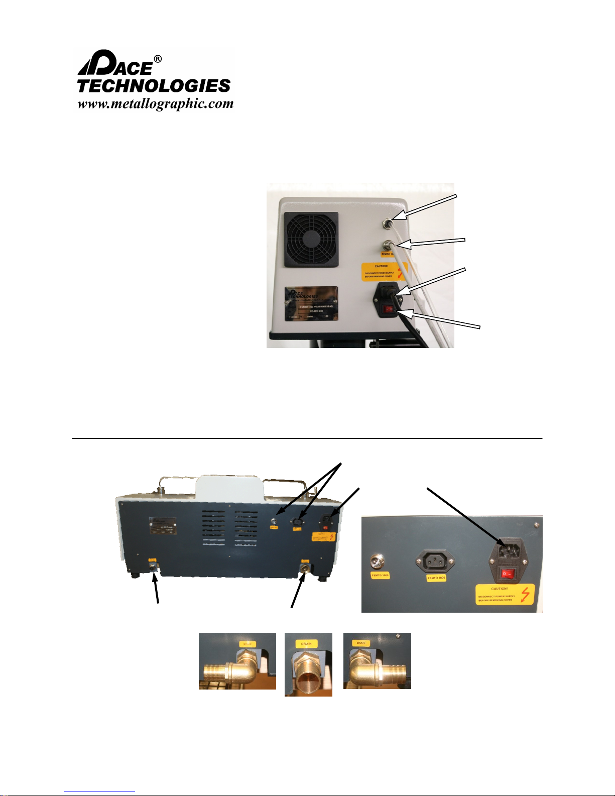
3.9 Backside connections
External air supply: It is recommended that the air supply be clean, filtered and
lubricated to extend the life and performance of the systems.
Electrical connection: Connect electrical power cable and communications cable.
Note: Inspect the operating voltage on the name plate.
FEMTO 1500 HEAD
External air
supply
Communication
cable to NANO
polishing base
Electrical
supply
Power
switch
NANO 2000 POLISHER
External water
supply
Please read this instruction manual carefully and follow all installation, operating and safety guidelines.
Water drain
FEMTO connections
Electrical connection
110V or 220V
Connect drain with the
best direction fitting
14
NANO 1000T / FEMTO 1500
Polishing Head
- - - - - - - - - - - - - - - - - - - - - - - - - - - - - - - - - - - - - - - - - - - - - - - - - - ▲ INSTRUCTION MANUAL
3601 E. 34th St. Tucson, AZ 85713 USA Tel. +1 520-882-6598 Fax +1 520-882-6599 email: pace@metallographic.com Web: http://www.metallographic.com
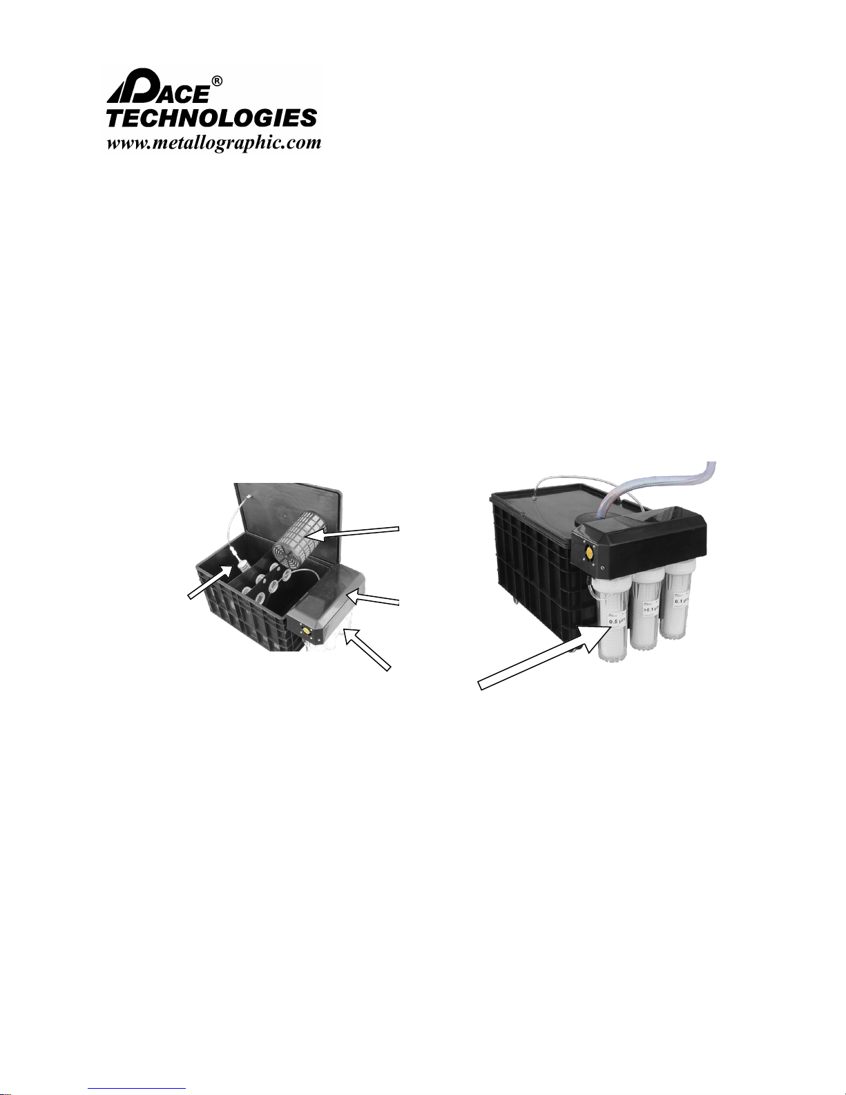
3.10 OPTIONAL Recirculating Filter System
Recirculating Filter System
The RC-1000 portable recirculating filter system allows for polishers to be mobile as well as to filter and
remove polishing swarf and abrasives generated from PACE Technologies NANO series polishers.
Utilizing a positive pressure pump, the recirculating filter system is able to provide clean water
containing <0.1 μm particles, thus eliminating waste flow to the building drainage system. The filtering
process begins with a coarse filter to eliminate coarse materials such as ripped polishing pads or torn
grinding papers. With a three chamber tank and counter current flow coarse abrasives can also settle
when the pump is not activated. As water is required, the pump will engage and pull the effluent
through a series of fine filters starting with a 0.5 μm filter, followed by a filter >0.1 μm and then to a sub
0.1 μm filter.
Pickup
screen
Coarse
Drain
Screen
Pump
Fine micron
exchangeable
filters
Please read this instruction manual carefully and follow all installation, operating and safety guidelines.
15
NANO 1000T / FEMTO 1500
Polishing Head
- - - - - - - - - - - - - - - - - - - - - - - - - - - - - - - - - - - - - - - - - - - - - - - - - - ▲ INSTRUCTION MANUAL
3601 E. 34th St. Tucson, AZ 85713 USA Tel. +1 520-882-6598 Fax +1 520-882-6599 email: pace@metallographic.com Web: http://www.metallographic.com
Installation (continued)
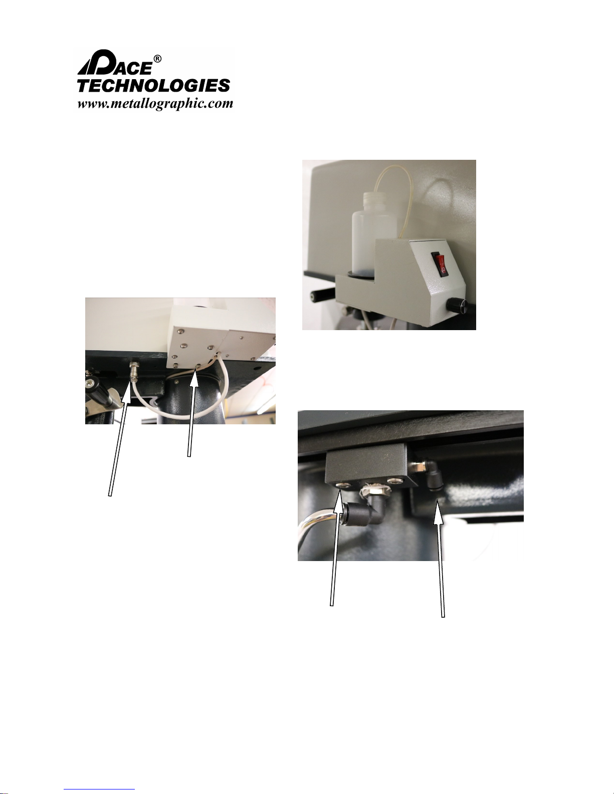
3.11 Lubricator Connection
Lubricator set-up (Tube through cap)
Fasten lubricator to
FEMTO base casting
Connect communication
cable to FEMTO base
Position dispensing tube
by sliding along rail. To
lock into place tighten
screws located under the
holder
Please read this instruction manual carefully and follow all installation, operating and safety guidelines.
Connect supply hose to
dispenser
16

NANO 1000T / FEMTO 1500
Polishing Head
- - - - - - - - - - - - - - - - - - - - - - - - - - - - - - - - - - - - - - - - - - - - - - - - - - ▲ INSTRUCTION MANUAL
3601 E. 34th St. Tucson, AZ 85713 USA Tel. +1 520-882-6598 Fax +1 520-882-6599 email: pace@metallographic.com Web: http://www.metallographic.com
4.0 Safety Guidelines
4.1 Warning Sign
4.2 Safety Precautions
This sign points to special safety features on the machine.
!
Careful attention to this instruction manual and the recommended safety guidelines is
!
essential for the safe operation of the FEMTO 1500.
Proper operator training is required for operation of the FEMTO 1500. Any unauthorized
mechanical and electrical change, as well as improper operation, voids all warranty
!
claims. All service issues need to be reported to the manufacturer / supplier.
Operate unit as specified in this manual.
!
Disconnect power before opening unit.
!
Do not leave any specimen or other parts on the working wheel.
!
Ensure that the air slots on polishing head are not obstructed.
!
When unit is not in use turn off water and air.
!
Keep hands clear of the specimen holder when the machine is running. Do not place or
position hands under specimen holder when it is in the raised position or when lowering
!
the head.
4.3 Emergency Statement
The FEMTO 1500 power head has been designed for polishing metallographic specimens up
to 2-inch diameter. Always follow proper operational guidelines and avoid contact with moving
parts, lubricants and abrasives. Seek appropriate medical care for cutting injuries.
Please read this instruction manual carefully and follow all installation, operating and safety guidelines.
17
NANO 1000T / FEMTO 1500
Polishing Head
- - - - - - - - - - - - - - - - - - - - - - - - - - - - - - - - - - - - - - - - - - - - - - - - - - ▲ INSTRUCTION MANUAL
3601 E. 34th St. Tucson, AZ 85713 USA Tel. +1 520-882-6598 Fax +1 520-882-6599 email: pace@metallographic.com Web: http://www.metallographic.com
4.4 Safety Test
The emergency stop switch on the NANO polisher controls the operation of the FEMTO 1500
power head when operated in the AUTO mode. Test the emergency stop switch by running
!
the FEMTO 1500 head in the AUTO mode through the NANO polisher. The following safety
check is considered important:
Emergency stop switch
Test:
Proper
Response:
Malfunction:
Corrective
measure:
Activate main power switch.
Start NANO 1000T/ FEMTO 1500
machine in AUTO mode.
Depress emergency stop switch.
NANO 1000T and FEMTO 1500 head
stops.
NANO 1000T or FEMTO 1500 polisher
does not lose power.
If system does not power down,
disconnect power supply cord and call
service technician.
Please read this instruction manual carefully and follow all installation, operating and safety guidelines.
18
NANO 1000T / FEMTO 1500
Polishing Head
- - - - - - - - - - - - - - - - - - - - - - - - - - - - - - - - - - - - - - - - - - - - - - - - - - ▲ INSTRUCTION MANUAL
3601 E. 34th St. Tucson, AZ 85713 USA Tel. +1 520-882-6598 Fax +1 520-882-6599 email: pace@metallographic.com Web: http://www.metallographic.com
5.0 Start-up and Operation
5.1 General
The FEMTO 1500 is an semi-automated grinding/ polishing accessory for the NANO polisher.
5.2 FEMTO 1500 Control Panel
Pressure
Gauge
Pressure
Adjustment
Pistons
Up/Down
Start / Stop buttons: Start/Stop the FEMTO head in the manual mode. Note the RUN/
STOP button on the NANO polisher controls the Automatic polishing
operation.
Motor
Speed
Controller
Wheel Speed
Indicator
Auto-mode for
timed grinding/
polishing
Manual Mode
Polishing
Start/Stop buttons
(manual mode)
Auto/ Manual buttons: Manual mode operates FEMTO independent of NANO polisher.
Pistons Up/Down: The UP/DOWN buttons control the pistons in the manual mode.
Motor Speed Controller: The FEMTO head has a variable speed motor (0-200 rpm).
Wheel Speed Indicator: Displays the motor speed (0-200 rpm)
Pressure Adjustment: Controls the pressure applied to the pistons.
Please read this instruction manual carefully and follow all installation, operating and safety guidelines.
Auto mode operates FEMTO in conjunction with NANO polisher.
19
8
0
1
2
3
4
5
6
7
8
9
10
11
12
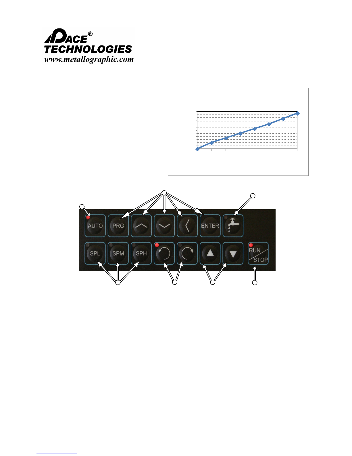
30 40 50 60 70 80 90 100
Applied Force per sample
(lbs)
Pressure gauge reading (PSI)
Applied Force per sample
NANO 1000T / FEMTO 1500
Polishing Head
- - - - - - - - - - - - - - - - - - - - - - - - - - - - - - - - - - - - - - - - - - - - - - - - - - ▲ INSTRUCTION MANUAL
3601 E. 34th St. Tucson, AZ 85713 USA Tel. +1 520-882-6598 Fax +1 520-882-6599 email: pace@metallographic.com Web: http://www.metallographic.com
5.2 FEMTO 1500 Control Panel
(applied force vs. pressure gauge)
5.3 NANO Polisher Control Panel
The NANO 1000T is a hand grinding/
polishing machine. By adding the FEMTO
power head, semi-automated polishing can
be accomplished.
Programming mode buttons
Auto-mode for timed
Water
button
grinding/ polishing
Preset speeds
(Low, medium, high)
Wheel
direction
Speed
control
RUN/STOP
Wheel direction: Clockwise rotation or counter clockwise rotation.
Run / Stop buttons: Start/stop the polishing wheel in both manual and auto mode.
Water button: Activates the water solenoid for the rinse bowl and rinse spout.
Preset speeds: Allows for faster speed control, SPL - low speed, SPM - medium
Auto-mode: Allows for running pre-programmed speeds and times (factory setting
Please read this instruction manual carefully and follow all installation, operating and safety guidelines.
speed, SPH - high speed (factory setting approx. 100, 200, 300 rpm.
approx. 200 rpm, FWD, 30 seconds).
20
NANO 1000T / FEMTO 1500
Polishing Head
- - - - - - - - - - - - - - - - - - - - - - - - - - - - - - - - - - - - - - - - - - - - - - - - - - ▲ INSTRUCTION MANUAL
3601 E. 34th St. Tucson, AZ 85713 USA Tel. +1 520-882-6598 Fax +1 520-882-6599 email: pace@metallographic.com Web: http://www.metallographic.com
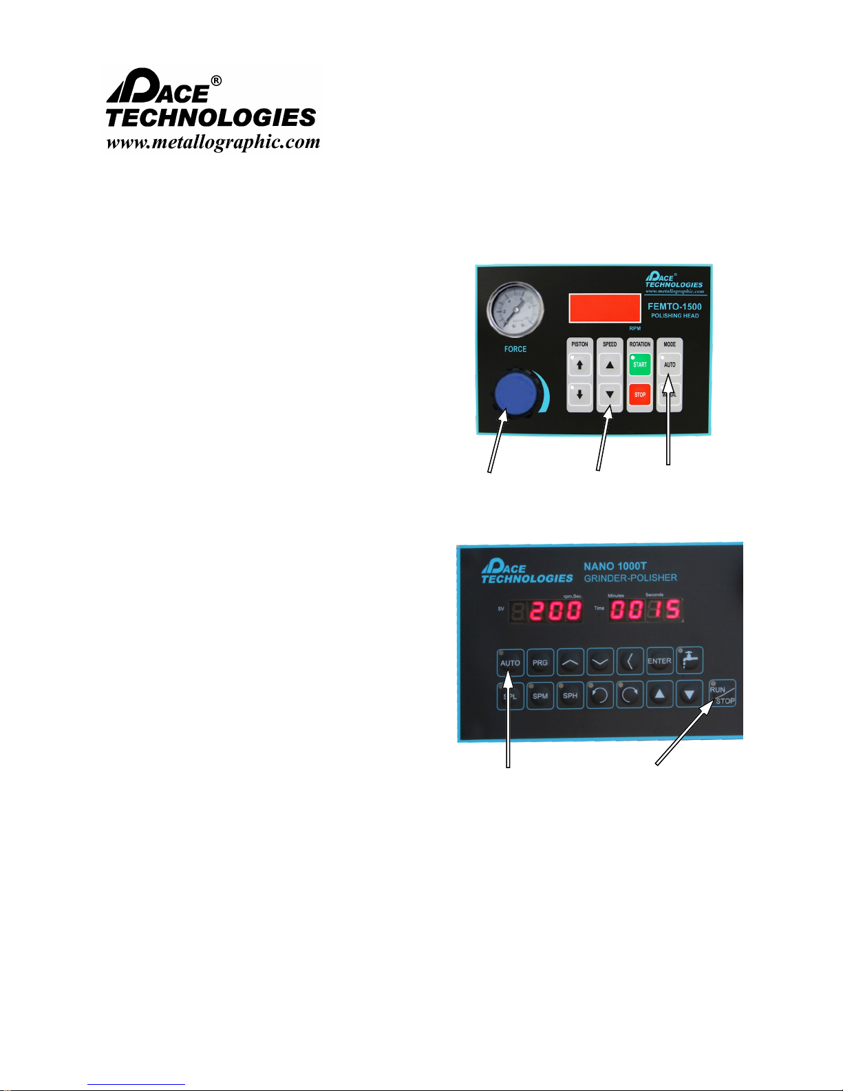
5.4 AUTO Polishing Mode
1. Install working wheel and attach grinding papers /
polishing cloths.
Position the specimen holder so that the sample
tracks over the entire diameter of the grinding
papers in order to break the grinding papers
uniformly. Note positioning is not as significant
for polishing pads.
2. Power on the FEMTO and NANO machines
using the power switch located on the back of the
units.
Find and press the AUTO button on the FEMTO,
a light will illuminate when selected
Set an approximate pressure and head speed on
the FEMTO head.
Adjust
polishing
force
Adjust
head
speed
Set to
Auto mode
3. Set the base speed, time and direction on the
NANO controller (see next page for instructions)
4. Rotate water spout over working wheel. During
sample preparation adjust water flow by turning
water control knob as required. Note: Initial
operation of water valve may contain air in the
lines. Turn water on slowly to purge air from
system.
4. Depress AUTO mode button on the NANO,
ensure red light is illuminated. To start operation
press RUN/STOP button.
5. Adjust speed of the polishing head and the
applied pressure
Set to Auto
mode
Starts Auto
polishing
mode
TIP: It is recommended that the FEMTO head speed match or
exceed the NANO base speed and run in the same direction. This
provides flatter specimen samples, especially for coarse grinding.
Please read this instruction manual carefully and follow all installation, operating and safety guidelines.
21

NANO 1000T / FEMTO 1500
Polishing Head
- - - - - - - - - - - - - - - - - - - - - - - - - - - - - - - - - - - - - - - - - - - - - - - - - - ▲ INSTRUCTION MANUAL
3601 E. 34th St. Tucson, AZ 85713 USA Tel. +1 520-882-6598 Fax +1 520-882-6599 email: pace@metallographic.com Web: http://www.metallographic.com
5.4.1 Programmable Mode
1. The programming mode can be used to pre-set the
polishing speed, direction and time for automated
polishing. It can also be used to change the Preset
speed buttons.
2. To change the speed of the wheel:
Press the PRG button and use the Up and Down
buttons to find SP1 and press ENTER. Use the up and
down < key to change the speed. Press ENTER to
save.
3. To program a grinding/ polishing time:
Press the PRG button and use the Up and Down
buttons to find t1 and press ENTER. Use the up and
down < key to change the time (enter in seconds displayed min-sec)
Preset speed buttons
4. To operate the pre-programmed conditions:
PRESS the AUTO button and then start the program
with the RUN/STOP button. The pre-programmed
conditions will be executed.
To change the speed setting for
the Preset speed buttons use
the following procedure:
Press the PRG button and use
the Up and Down buttons to SL
(slow speed) and press ENTER.
Use the up and down < key to
change the speed. Use Sn for
changing the medium speed
and SH for the fast speed.
Please read this instruction manual carefully and follow all installation, operating and safety guidelines.
22

NANO 1000T / FEMTO 1500
Polishing Head
- - - - - - - - - - - - - - - - - - - - - - - - - - - - - - - - - - - - - - - - - - - - - - - - - - ▲ INSTRUCTION MANUAL
3601 E. 34th St. Tucson, AZ 85713 USA Tel. +1 520-882-6598 Fax +1 520-882-6599 email: pace@metallographic.com Web: http://www.metallographic.com
5.5 MANUAL NANO-FEMTO Polishing Mode
1. Install working wheel and attach grinding
papers / polishing cloths.
2. Power on the FEMTO and NANO machines
using the power switch located on the back of
the units.
Find and press the MANUAL button on the
FEMTO, a light will illuminate when selected
Set an approximate pressure and head speed on
the FEMTO head.
Load samples and lower the Pistons to the
DOWN position.
Press green Start button to start the FEMTO
head (NANO polisher will not start automatically
in this mode, it must be started separately).
Adjust the FEMTO speed and force.
Adjust
polishing
force
Press to
lower
pistons
Adjust
head
speed
Start/Stop
FEMTO head
Set to
Manual
3. Start the NANO head by using preset speeds
(SPL, SPM, SPH) and pressing RUN/STOP
button. Note speed can be adjusted with up and
down arrow keys.
4. Rotate water spout over working wheel. During
sample preparation adjust water flow by turning
water control knob as required. Note: Initial
operation of water valve may contain air in the
lines. Turn water on slowly to purge air from
system.
5. Both the NANO and FEMTO heads need to be
stopped by pressing the red STOP button on the
FEMTO head and also the RUN/STOP button on
the NANO controller.
Please read this instruction manual carefully and follow all installation, operating and safety guidelines.
Preset
Start/Stop
NANO
manually
23

NANO 1000T / FEMTO 1500
Polishing Head
- - - - - - - - - - - - - - - - - - - - - - - - - - - - - - - - - - - - - - - - - - - - - - - - - - ▲ INSTRUCTION MANUAL
3601 E. 34th St. Tucson, AZ 85713 USA Tel. +1 520-882-6598 Fax +1 520-882-6599 email: pace@metallographic.com Web: http://www.metallographic.com
5.6 SEMI-AUTO NANO-FEMTO Polishing Mode
1. Install working wheel and attach grinding papers /
polishing cloths.
2. Power on the FEMTO and NANO machines
using the power switch located on the back of the
units.
Find and press the AUTO button on the FEMTO
control panel
Set an approximate pressure and head speed on
the FEMTO head.
Load samples.
3. Start the NANO head by using preset speeds
(SPL, SPM, SPH) and pressing RUN/STOP
button. Note speed can be adjusted with up and
down arrow keys.
Adjust the FEMTO speed and force.
The FEMTO head and NANO polisher will start
automatically in this mode, however, it will run
until the RUN/STOP button is pressed.
Adjust
polishing
force
Adjust
head
speed
Set to
Auto
mode
4. Position flexible water spout over working wheel.
During sample preparation adjust water flow by
turning water control knob as required. Note:
Initial operation of water valve may contain air in
the lines. Turn water on slowly to purge air from
system.
5. Press the RUN/STOP button on the NANO
controller to stop the polishing operation.
Please read this instruction manual carefully and follow all installation, operating and safety guidelines.
Preset
Speeds
Start/Stop
NANO
manually
24

NANO 1000T / FEMTO 1500
Polishing Head
- - - - - - - - - - - - - - - - - - - - - - - - - - - - - - - - - - - - - - - - - - - - - - - - - - ▲ INSTRUCTION MANUAL
3601 E. 34th St. Tucson, AZ 85713 USA Tel. +1 520-882-6598 Fax +1 520-882-6599 email: pace@metallographic.com Web: http://www.metallographic.com
457 MANUAL Hand Polishing Mode (NANO ONLY)
To use the NANO polishing without the FEMTO head, turn off the power to the FEMTO head
using the main power switch on the back of the FEMTO head.
Swing the FEMTO head out of the way.
5.7.1 Grinding / polishing by hand
1. Install working wheel and attach grinding papers / polishing cloths.
2. Power on the machine in the back and set the mode, speed, and time (if required).
3. Rotate water spout over working wheel. During sample preparation adjust water flow by
turning water control knob as required. Note: Initial operation of water valve may contain
air in the lines. Turn water on slowly to purge air from system.
4. Press RUN/STOP start and stop the machine in the manual mode.
5.7.2 Direction and speed controller (manual)
1. To change direction of the wheel:
-Press FWD (clockwise) or REV (counter clockwise),
LED will light
2. To change the speed of the wheel:
Select one of the low, medium or high preset speed
buttons and use the Up and Down arrows to fine tune
speed if required
Please read this instruction manual carefully and follow all installation, operating and safety guidelines.
25

NANO 1000T / FEMTO 1500
Polishing Head
- - - - - - - - - - - - - - - - - - - - - - - - - - - - - - - - - - - - - - - - - - - - - - - - - - ▲ INSTRUCTION MANUAL
3601 E. 34th St. Tucson, AZ 85713 USA Tel. +1 520-882-6598 Fax +1 520-882-6599 email: pace@metallographic.com Web: http://www.metallographic.com
5.8 Manual Mode - Programming changes
1. The programming mode can be used to pre-set
the polishing speed, direction and time for
automated polishing. It can also be used to
change the Preset speed buttons.
2. To change the speed of the wheel:
Press the PRG button and use the Up and Down
buttons to find SP1 then press ENTER. Use the
Up and Down buttons to change the speed, press
ENTER to finalize the change.
3. To program a grinding/ polishing time:
Press the PRG button and use the Up and Down
buttons to find ST1 and press ENTER. Use the
Up and Down buttons to change the time
(seconds), press ENTER to finalize the change.
4. To operate the pre-programmed conditions:
Press the AUTO button and then start the
program with the RUN/STOP button. The preprogrammed conditions will be executed.
Preset
Speeds
To change the speed setting for
the Preset speed buttons use
the following procedure:
Press the PRG button and use
the Up and Down keys to find
SL (slow speed) then press
ENTER. Use the Up and Down
button to change the speed.
Use SN for changing the
medium speed and SH for the
fast speed presets.
Start/Stop
NANO
manually
Please read this instruction manual carefully and follow all installation, operating and safety guidelines.
26

NANO 1000T / FEMTO 1500
Polishing Head
- - - - - - - - - - - - - - - - - - - - - - - - - - - - - - - - - - - - - - - - - - - - - - - - - - ▲ INSTRUCTION MANUAL
3601 E. 34th St. Tucson, AZ 85713 USA Tel. +1 520-882-6598 Fax +1 520-882-6599 email: pace@metallographic.com Web: http://www.metallographic.com
5.9 Positioning and Loading FEMTO holder
1. For grinding with abrasive papers, the specimen holder
for the FEMTO head should be positioned so that the
specimen tracks over the entire radius of the grinding
paper.
Since grinding papers break down relatively fast, it is
recommended that the hardest part of the mount
(typically the specimen) track over the entire radius in
order to uniformly break down the grinding papers. If
the specimen does not break down the grinding papers
uniformly then the softer outside part of the mount will
grind more. The result is after polishing there will be a
portion of the mount which is not fully polished. This
portion of the mount will appear as a crescent shaped
moon and can cause issues when examining the edge
of the specimen.
TIP: If you have small samples, mount them toward
the outside edge of the mount for better tracking
Position holder so that the
specimen in the mount tracks over
then entire radius of the grinding
paper.
2. Individual specimen holders do not hold the specimen
in the holder. When the head is lifted, the specimens
will remain on the working wheel. In such a case they
will need to be reloaded after changing the abrasive.
TIP: By placing a rubber O-ring around the top of the
mount it can be lifted when the head is raised and held
in place. Note you most likely will not be able to do this
if you use the splash guards.
You can use O-rings to hold
specimens in place when
head is lifted
Please read this instruction manual carefully and follow all installation, operating and safety guidelines.
27
NANO 1000T / FEMTO 1500
Polishing Head
- - - - - - - - - - - - - - - - - - - - - - - - - - - - - - - - - - - - - - - - - - - - - - - - - - ▲ INSTRUCTION MANUAL
3601 E. 34th St. Tucson, AZ 85713 USA Tel. +1 520-882-6598 Fax +1 520-882-6599 email: pace@metallographic.com Web: http://www.metallographic.com
5.10 Metallographic Specimen Preparation Basics
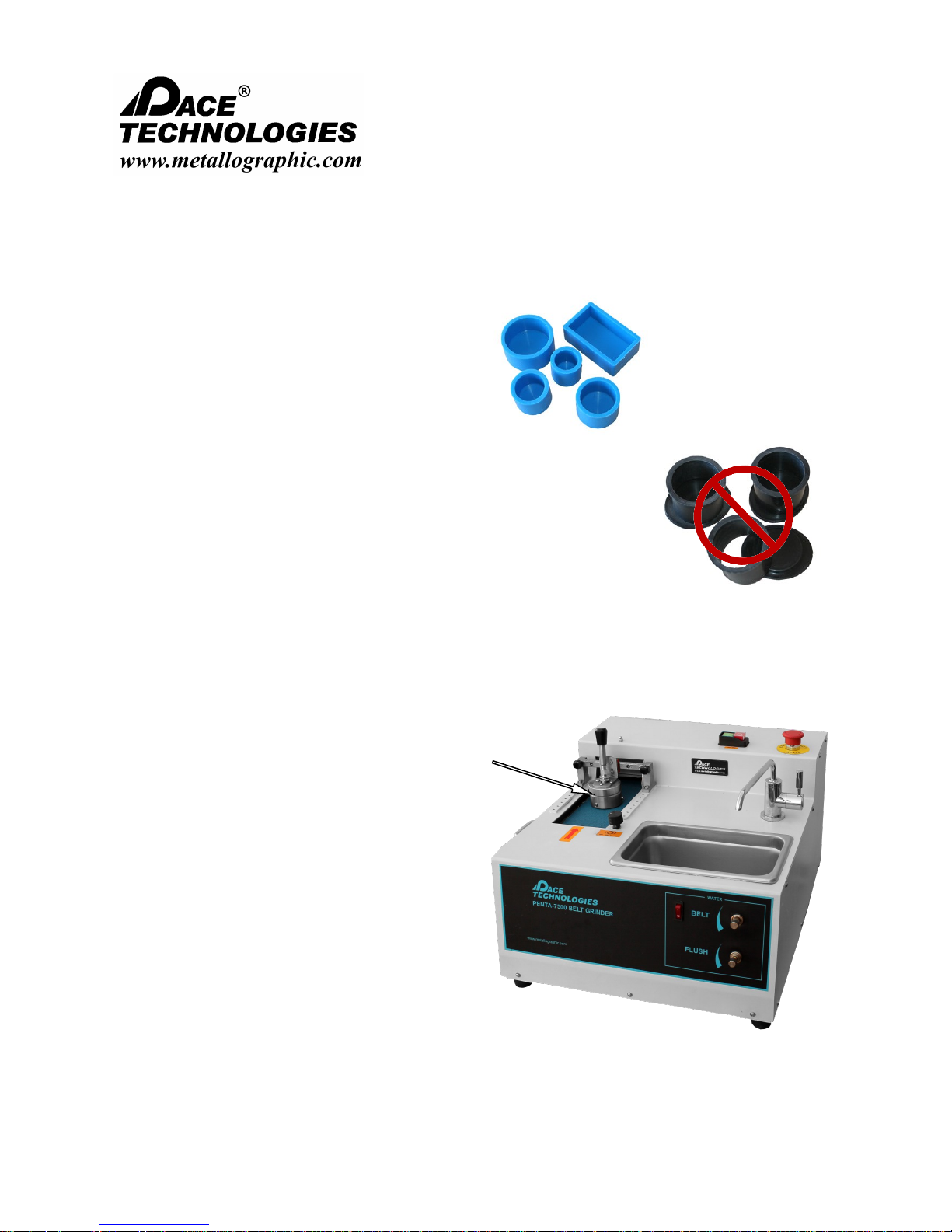
TIP: To optimize individual polishing
Rubber molds produce
square mounts
machines, the specimen mounts need
to be square. It is recommended that
the specimen be mounted in either a
compression mounting press or with a
rubber mold for castable mounting.
DO NOT USE TAPERED 2-PIECE
MOLDING CUPS for Individual
Specimen Polishing machines.
2-piece molds produce
tapered mounts
USE A BELT GRINDER OR CENTRAL POLISHING FORCE
FIXTURE FOR COARSE GRINDING!!!
Square grinding
attachment
TIP: Individual polishing machines
DO NOT require coarse planar
grinding. In fact, extremely coarse
grinding with 60 grit down to 180 grit
is not recommended.
If coarse grinding is required, it is
recommended that the PENTA 7500
belt grinder, with its square grinding
attachment be used. The FEMTO
1500 with the central sample fixture
can also be used (see Section 1.5)
Please read this instruction manual carefully and follow all installation, operating and safety guidelines.
28

NANO 1000T / FEMTO 1500
Polishing Head
- - - - - - - - - - - - - - - - - - - - - - - - - - - - - - - - - - - - - - - - - - - - - - - - - - ▲ INSTRUCTION MANUAL
3601 E. 34th St. Tucson, AZ 85713 USA Tel. +1 520-882-6598 Fax +1 520-882-6599 email: pace@metallographic.com Web: http://www.metallographic.com
5.10 Metallographic Specimen Preparation Basics (continued)
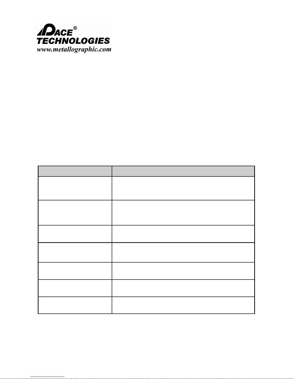
A typical metallographic specimen preparation consists of the following basic steps:
Preparation Stage Purpose
Initial documentation:
Sectioning / cutting:
Rough, or planar grinding
(refer to Section 4.9.1):
Rough polishing (refer to
Section 4.9.2):
Final polishing (refer to
Section 4.9.1)::
Etching:
Examination:
To document the initial condition of the sample,
To map the sample surface,
To highlight the area of interest.
To reduce the size of large samples and to sample the
specimens close to the area of interest.
To obtain a planar surface,
To remove sectioning damage,
To approach the area of interest.
Ideally to remove all the subsurface damage and microstructural
damage produced during cutting and rough grinding (Superficial
scratches may still be present after this step).
Generally, more for cosmetic purposes than for removing
microstructural damage. In most cases, this stage should be
minimized to avoid over polishing and distorting the
microstructural features.
To enhance microstructural features such as grain boundaries,
grain size, phase differences, etc.
A variety of examination techniques are used in metallography,
including: optical microscopy, electron microscopy and hardness
testing.
Please read this instruction manual carefully and follow all installation, operating and safety guidelines.
29
NANO 1000T / FEMTO 1500
Polishing Head
- - - - - - - - - - - - - - - - - - - - - - - - - - - - - - - - - - - - - - - - - - - - - - - - - - ▲ INSTRUCTION MANUAL
3601 E. 34th St. Tucson, AZ 85713 USA Tel. +1 520-882-6598 Fax +1 520-882-6599 email: pace@metallographic.com Web: http://www.metallographic.com
5.10.1 Rough / Planar Grinding
Rough or planar grinding, is required to produce flat specimens and to reduce the damage created by
sectioning. The planar grinding step is accomplished by decreasing the abrasive grit particle size
sequentially to obtain surface finishes that are ready for polishing. Care must be taken to avoid being
too abrasive in this step, and actually creating greater specimen damage than produced during cutting.
This is especially true for very brittle materials such as ceramics and silicon.
The machine parameters which affect the preparation of metallographic specimens include: grinding /
polishing pressure, grinding direction, and the relative velocity distribution between the specimen and
the polishing wheel.
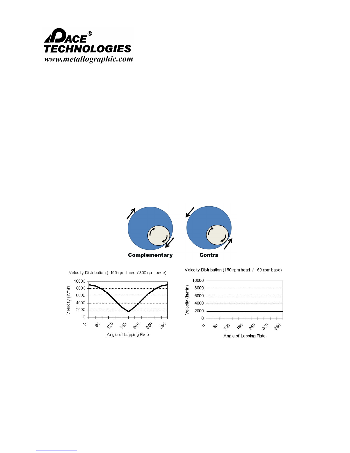
Grinding Speed
For automated polishing the relative speed between the polishing head and the polishing wheel has a
significant effect on the flatness of the mount, especially for grinding with coarse abrasives. As an
example, the following two conditions show the effect of running with the head and base speed in the
contra direction as well as running the head and base speeds in the same direction at the same speed.
High relative velocity difference (contra)
between the polishing head and polishing base
Low relative velocity difference
(complementary) between the polishing head
and polishing base
Based on the relative velocity distributions for grinding / polishing the best condition for maintaining a
uniform velocity across the specimen as it rotates around the polishing wheel is to run them in the
same direction at the same speed. In addition, changing the offset as well as the combination speed
Please read this instruction manual carefully and follow all installation, operating and safety guidelines.
30
NANO 1000T / FEMTO 1500
Polishing Head
- - - - - - - - - - - - - - - - - - - - - - - - - - - - - - - - - - - - - - - - - - - - - - - - - - ▲ INSTRUCTION MANUAL
3601 E. 34th St. Tucson, AZ 85713 USA Tel. +1 520-882-6598 Fax +1 520-882-6599 email: pace@metallographic.com Web: http://www.metallographic.com
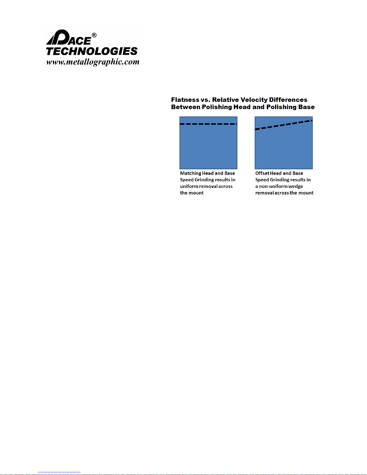
can control the aggressiveness of the
grinding/ polishing operation.
It is also very important for polishing
machines which use individual force
pistons for applying the polishing force to
run the power head and base at closely
matching speeds and in the
complementary direction. If these
machines are run with significantly different
speeds or direction the mount will have a
tendency to grind with a wedge and
therefore it will not be square.
Grinding Pressure
Grinding / polishing pressure is dependent upon the applied force (pounds or Newton's) and the area
of the specimen and mounting material. Pressure is defined as the Force/Area (psi, N/m2 or Pa). For
specimens significantly harder than the mounting compound, pressure is better defined as the force
divided by the specimen surface area. Thus, for larger hard specimens, higher grinding / polishing
pressures increase stock removal rates. However, higher pressure also increases the amount of
surface and subsurface damage produced in the specimen.
Note regarding SiC grinding papers: as the abrasive grains dull and cut rates decrease, increasing
grinding pressures can extend the life of the SiC paper.
Higher grinding / polishing pressures can also generate additional frictional heat which may be
beneficial for the chemical mechanical polishing (CMP) of ceramics, minerals and composites.
Likewise for extremely friable specimens (such as nodular cast iron), higher pressures and lower
relative velocity distributions can aid in retaining inclusions and secondary phases.
Grinding Direction
The orientation of the specimen can have a significant impact on the preparation results, especially for
specimens with coatings. In general, when grinding and polishing materials with coatings, the brittle
component should be kept in compression. In other words, for brittle coatings, the direction of the
abrasive should be through the coating and into the substrate. Conversely, for brittle substrates with
ductile coatings, the direction of the abrasive should be through the brittle substrate and into the
ductile coating.
Manual Preparation
In order to ensure that the previous rough grinding damage is removed when grinding by hand, the
specimen should be rotated 90 degrees and continually ground until all of the scratches from the
previous grinding direction are removed. When necessary, the abrasive paper should be replaced with
a newer paper to maintain cutting rates.
Please read this instruction manual carefully and follow all installation, operating and safety guidelines.
31
NANO 1000T / FEMTO 1500
Polishing Head
- - - - - - - - - - - - - - - - - - - - - - - - - - - - - - - - - - - - - - - - - - - - - - - - - - ▲ INSTRUCTION MANUAL
3601 E. 34th St. Tucson, AZ 85713 USA Tel. +1 520-882-6598 Fax +1 520-882-6599 email: pace@metallographic.com Web: http://www.metallographic.com
5.10.2 Rough Polishing
The purpose of the rough polishing step is to remove the damage produced during cutting and planar
grinding. Proper rough polishing will maintain specimen flatness and retain all inclusions or
secondary phases. By eliminating the previous damage and maintaining the microstructural integrity
of the specimen at this step, a minimal amount of time is required to remove the cosmetic damage at
the final polishing step.
Rough polishing is accomplished primarily with diamond abrasives ranging from 9 micron to 1
micron. Polycrystalline diamond -- because of its multiple and small cutting edges -- produces high
cut rates with minimal surface damage. Therefore, polycrystalline diamond abrasives are
recommended for metallographic rough polishing on low-napped polishing cloths.
Rough Polishing Guidelines
Material Recommendations
Metals (ferrous, non-ferrous,
tool steels, superalloys, etc.)
Ceramics and ceramic matrix
composites (CMC)
Polymer matrix composites
(PMC)
Biomaterials
Microelectronic specimens Diamond-lapping films are recommended.
Plastics and polymers 800 and 1200 grit SiC abrasive paper are recommended.
Plasma spray materials
Rough polishing typically requires two polishing steps, e.g., a 6micron diamond followed by a 1-micron diamond on low-napped
polishing cloths.
Low-nap polishing pads using polycrystalline diamond, alternating
with colloidal silica. This provides a chemical mechanical
polishing (CMP) effect which results in a damage-free surface
Diamond-lapping films are recommended.
Low-napped polishing pads with polycrystalline diamond,
alternating with colloidal silica. Alternatively, diamond-lapping
films may work well.
Diamond-lapping films or low-napped polishing pads with
alternating diamond and colloidal silica abrasives.
Please read this instruction manual carefully and follow all installation, operating and safety guidelines.
32

NANO 1000T / FEMTO 1500
Polishing Head
- - - - - - - - - - - - - - - - - - - - - - - - - - - - - - - - - - - - - - - - - - - - - - - - - - ▲ INSTRUCTION MANUAL
3601 E. 34th St. Tucson, AZ 85713 USA Tel. +1 520-882-6598 Fax +1 520-882-6599 email: pace@metallographic.com Web: http://www.metallographic.com
5.10.3 Final Polishing
The purpose of final polishing is to remove only the cosmetic surface damage. It should not be used
to remove any damage remaining from cutting and planar grinding. If the damage from these steps is
not completely removed, the rough polishing step should be repeated or continued.
Final Polishing Guidelines
Material Recommendation
Metals (ferrous, nonferrous, tool steels, super
alloys, etc.)
Ceramics and ceramic
matrix composites (CMC)
Polymer matrix composites
(PMC)
Biomaterials
Microelectronic specimens
Plastics and polymers Light polish with alumina on a high-napped polishing pad.
Plasma spray materials
High-napped polishing pads with a nanometer alumina polishing
abrasive. The polishing times should nominally be less than 30
seconds.
Low-napped polishing pads using 1-um polycrystalline diamond,
alternating with colloidal silica or colloidal silica alone.
Fine abrasive diamond-lapping films, followed by a very light polish
on a high-napped polishing pad.
Low-napped polishing pads with polycrystalline diamond, alternating
with colloidal silica.
Diamond-lapping films followed by a very light polish on a
high-napped polishing pad.
Diamond-lapping films followed by a very light and short alumina or
colloidal silica polish on a high-napped polishing pad.
Please read this instruction manual carefully and follow all installation, operating and safety guidelines.
33

NANO 1000T / FEMTO 1500
Polishing Head
- - - - - - - - - - - - - - - - - - - - - - - - - - - - - - - - - - - - - - - - - - - - - - - - - - ▲ INSTRUCTION MANUAL
3601 E. 34th St. Tucson, AZ 85713 USA Tel. +1 520-882-6598 Fax +1 520-882-6599 email: pace@metallographic.com Web: http://www.metallographic.com
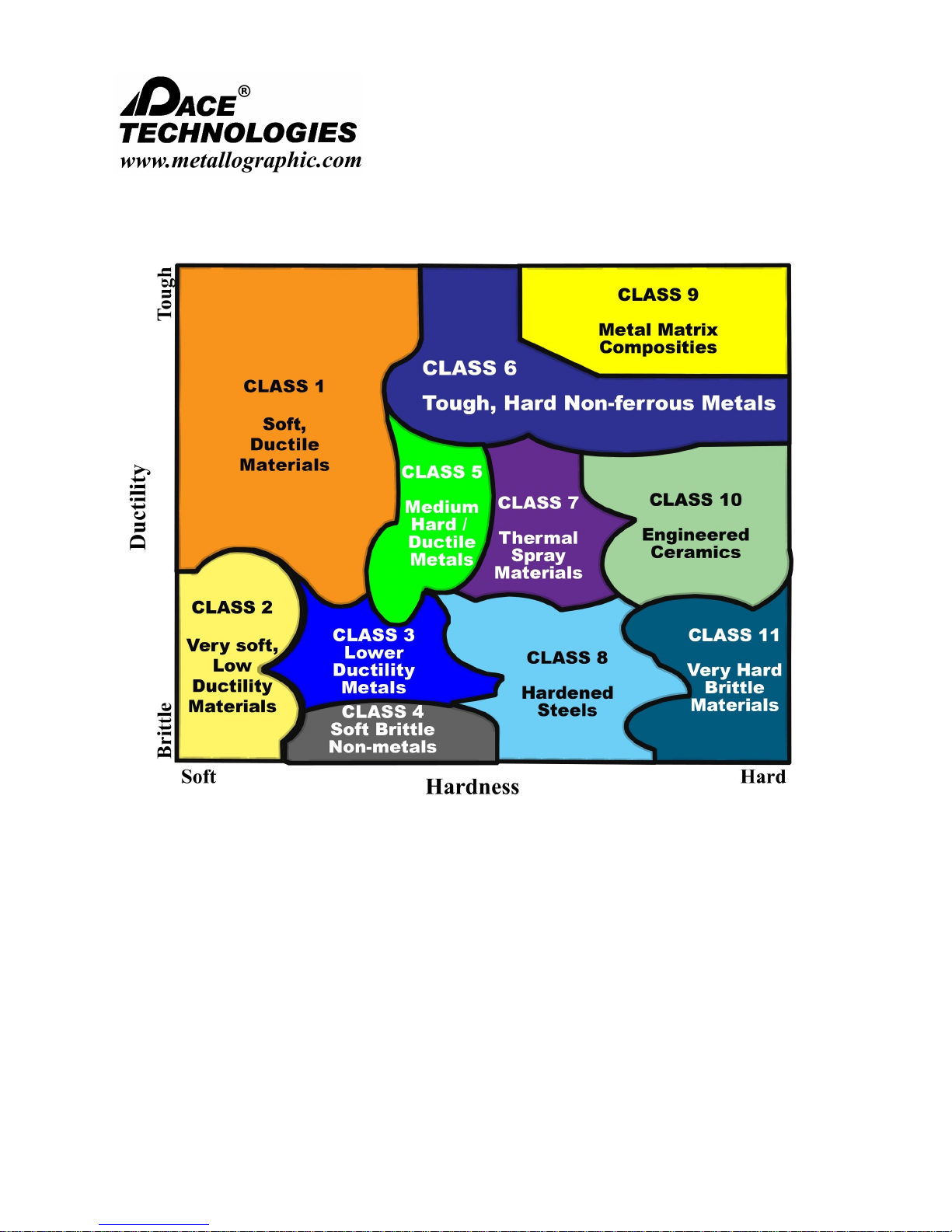
5.11 Selected Polishing Procedures
Metallographic specimen preparation requires knowledge of the specimen properties, the most
important characteristics are the hardness and ductility of the metallographic specimen. Based
on these material properties, the proper metallographic consumables and equipment parameters can be determined. The following chart shows the hardness and ductility for most metallographic material classes that are analyzed by metallographic techniques. Specimen procedures
Please read this instruction manual carefully and follow all installation, operating and safety guidelines.
34
NANO 1000T / FEMTO 1500
Polishing Head
- - - - - - - - - - - - - - - - - - - - - - - - - - - - - - - - - - - - - - - - - - - - - - - - - - ▲ INSTRUCTION MANUAL
3601 E. 34th St. Tucson, AZ 85713 USA Tel. +1 520-882-6598 Fax +1 520-882-6599 email: pace@metallographic.com Web: http://www.metallographic.com
Please read this instruction manual carefully and follow all installation, operating and safety guidelines.
35
NANO 1000T / FEMTO 1500
Polishing Head
- - - - - - - - - - - - - - - - - - - - - - - - - - - - - - - - - - - - - - - - - - - - - - - - - - ▲ INSTRUCTION MANUAL
3601 E. 34th St. Tucson, AZ 85713 USA Tel. +1 520-882-6598 Fax +1 520-882-6599 email: pace@metallographic.com Web: http://www.metallographic.com
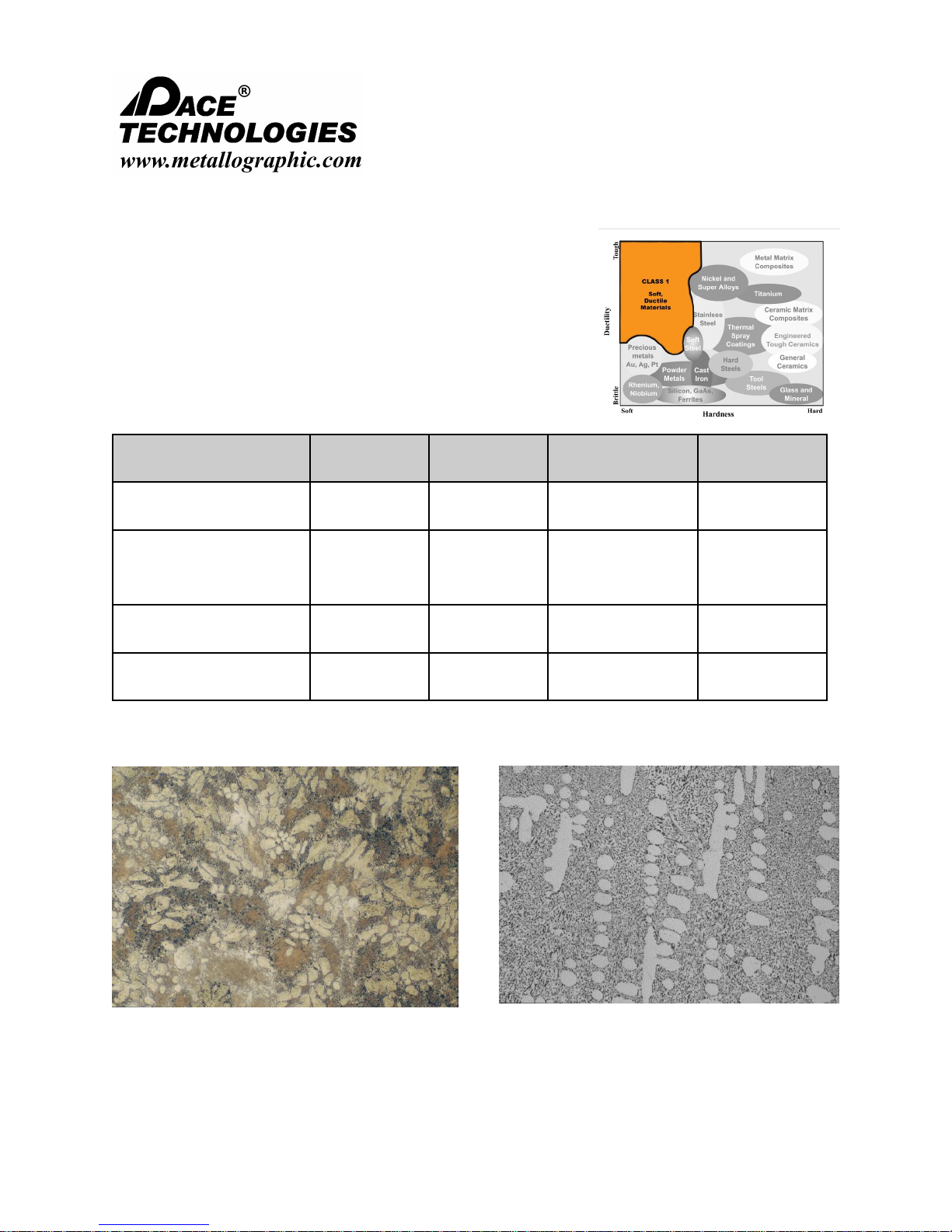
CLASS 1 Polishing Procedures
5.11.1 Aluminum and Aluminum Alloys
Aluminum and aluminum alloys are difficult to prepare because
they are soft and contain oxide particles which can become
dislodged and scratch the surface. The key to polishing aluminum
is to use very fine polishing abrasives (fine aggregates).
Abrasive/surface Lubricant
P120 grit ALO paper*
P220 grit ALO paper*
P220 grit ALO paper
P500 grit ALO paper
P1200 grit ALO paper
1 um DIAMAT diamond on
ATLANTIS pad
0.05 um Nanometer alumina on
NAPPAD pad
Water
Water
DIALUBE Purple
Extender
60-75 1 minute 100 rpm / 100 rpm
FEMTO pressure
setting (psi)
60-75 200 rpm / 200 rpm
60-75
60-75 2 minutes 200 rpm / 200 rpm
200 rpm / 200 rpm
* Recommended for Central Force holders (this step not required for Individual Force holders)
Time Head / Wheel speed
Until plane
1 minute
Until plane
1 minute
1 minute
Aluminum-Silicon Alloy, B.F. 200X
Please read this instruction manual carefully and follow all installation, operating and safety guidelines.
Aluminum-Silicon Alloy, B.F. 200X
36
NANO 1000T / FEMTO 1500
Polishing Head
- - - - - - - - - - - - - - - - - - - - - - - - - - - - - - - - - - - - - - - - - - - - - - - - - - ▲ INSTRUCTION MANUAL
3601 E. 34th St. Tucson, AZ 85713 USA Tel. +1 520-882-6598 Fax +1 520-882-6599 email: pace@metallographic.com Web: http://www.metallographic.com
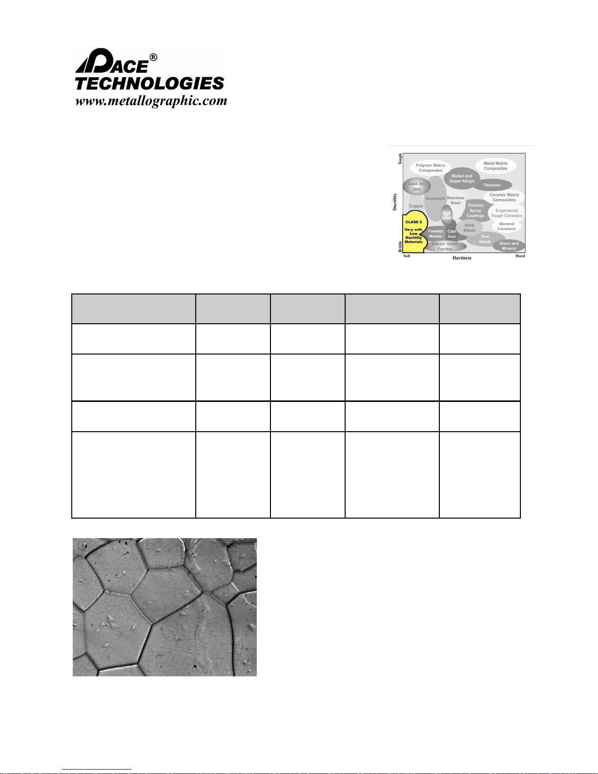
CLASS 2 Polishing Procedures
5.11.2 Rhenium and Refractory Alloys
Refractory metals such as Rhenium, Niobium, Tungsten and Molybdenum are
a very soft, and any loose or fracture abrasive particles can easily embed. This
makes specimen preparation very difficult because it gums up diamond
grinding disks or becomes embedded with fractured SiC particles when ground
with SiC papers. The key to preparation of this material is to use the tougher
alumina abrasive and to chemically etch the specimen between each grinding
step. The purpose of etching is to remove the embedded particles and not carry
them over as contamination.
Abrasive/surface Lubricant
P120 grit ALO paper*
P220 grit ALO paper*
P220 grit ALO paper
P500 grit ALO paper
P1200 grit ALO paper
1 um DIAMAT diamond on
ATLANTIS pad
Water
Water
DIALUBE Purple
Extender
FEMTO pressure
setting (psi)
60-75
60-75
60-75 2 minutes
100/100 rpm
100/100 rpm
100/100 rpm
Polishing with
10% Diluted
0.05 um acidic Nanometer
acid alumina on a
BLACKCHEM 2 pad
etchant below:
5-10 lbs 1 minute 100/100 rpm
Rhenium - 30 ml
lactic acid, 30 ml
HNO3, 1 ml HF
* Recommended for Central Force holders (this step not required for Individual Force holders)
Time Head / Wheel speed
Until plane
1 minute
Until plane
1 minute
1 minute
Please read this instruction manual carefully and follow all installation, operating and safety guidelines.
Rhenium (BF), etched
37

NANO 1000T / FEMTO 1500
Polishing Head
- - - - - - - - - - - - - - - - - - - - - - - - - - - - - - - - - - - - - - - - - - - - - - - - - - ▲ INSTRUCTION MANUAL
3601 E. 34th St. Tucson, AZ 85713 USA Tel. +1 520-882-6598 Fax +1 520-882-6599 email: pace@metallographic.com Web: http://www.metallographic.com
CLASS 3 Polishing Procedures
5.11.3 Cast Irons
Cast irons are difficult materials to prepare properly because the
graphite nodules (or graphite flakes) are easily pulled out during
preparation. By minimizing the sectioning damage and by
starting with a modest-grit-size SiC paper, retaining these difficult
particles can be accomplished.
Abrasive/surface Lubricant
120 grit SiC paper*
240 grit SiC paper*
360 grit SiC paper
600 grit SiC paper
800 grit SiC paper
1200 grit SiC paper
1 um DIAMAT diamond on
GOLDPAD pad
0.05 um Nanometer alumina
on TRICOTE pad
* Recommended for Central Force holders (this step not required for Individual Force holders)
Water 5-10 lbs 200/200 rpm
Water 5-10 lbs 200/200 rpm
DIALUBE
Purple Extender
5-10 lbs 100/100 rpm 1 minute
FEMTO pressure
setting (psi)
5-10 lbs 200/200 rpm 2 minutes
Head / Wheel speed Time
Until plane
1 minute 1 minute
1 minute
1 minute
1 minute
1 minute
Nodular Cast Iron microstructure, Etchant 2%
Nital, Mag. 100X
Please read this instruction manual carefully and follow all installation, operating and safety guidelines.
Graphite Cast Iron microstructure, Etchant 2%
Nital, Mag. 500X
38

NANO 1000T / FEMTO 1500
Polishing Head
- - - - - - - - - - - - - - - - - - - - - - - - - - - - - - - - - - - - - - - - - - - - - - - - - - ▲ INSTRUCTION MANUAL
3601 E. 34th St. Tucson, AZ 85713 USA Tel. +1 520-882-6598 Fax +1 520-882-6599 email: pace@metallographic.com Web: http://www.metallographic.com
CLASS 4 Polishing Procedures
5.11.4 Microelectronics
The microstructural preparation of electronic packages presents some very
difficult challenges, such as abrasives embedding in very soft solder joints,
edge rounding, polishing relief between very hard (ceramic) or brittle
(silicon) materials and the very soft plastic and metal solders. The use of
alumina lapping films are very useful for maintaining flatness and for
minimizing fractured abrasive embedding for non-ceramic substrates. For
specimens with ceramic substrates, diamond lapping films are recommended.
Abrasive/surface Lubricant
30 micron alumina lapping
film*
15 micron alumina lapping
film*
9 micron alumina lapping
film
6 micron alumina lapping
film
3 micron alumina lapping
film
1 um DIAMAT diamond on
ATLANTIS polishing pad
SIAMAT colloidal silica on a
MICROPAD polishing pad
* Recommended for Central Force holders (this step not required for Individual Force holders)
POLYLUBE
Extender
POLYLUBE
Extender
POLYLUBE
Extender
POLYLUBE
Extender
POLYLUBE
Extender
DIALUBE
Purple Extender
5-10 lbs 100/100 rpm 1 minute
FEMTO pressure
setting (psi)
5-10 lbs 100/100 rpm Until plane
5-10 lbs 100/100 rpm 1-2 minutes
5-10 lbs 100/100 rpm 1-2 minutes
5-10 lbs 100/100 rpm 1-2 minutes
5-10 lbs 100/100 rpm 1-2 minutes
5-10 lbs 100/100 rpm 1-2 minutes
Head / Wheel speed Time
Electronic die cross section
Please read this instruction manual carefully and follow all installation, operating and safety guidelines.
Electronic die cross section
39

NANO 1000T / FEMTO 1500
Polishing Head
- - - - - - - - - - - - - - - - - - - - - - - - - - - - - - - - - - - - - - - - - - - - - - - - - - ▲ INSTRUCTION MANUAL
3601 E. 34th St. Tucson, AZ 85713 USA Tel. +1 520-882-6598 Fax +1 520-882-6599 email: pace@metallographic.com Web: http://www.metallographic.com
CLASS 5 Polishing Procedures
5.11.5 Stainless Steels
Stainless steels have high concentrations of chromium (>12%) and are
generally relatively soft as compared to heat treated steels. This makes
stainless steel more susceptible to smearing. Preparation is relatively
straight forward.
Abrasive/surface Lubricant
120 grit SiC paper*
240 grit SiC paper*
360 grit SiC paper
600 grit SiC paper
800 grit SiC paper
1200 grit SiC paper
1 um DIAMAT diamond on
GOLDPAD polishing pad
0.05 um Nanometer alumina
on TRICOTE polishing pad
* Recommended for Central Force holders (this step not required for Individual Force holders)
Water 5-10 lbs 200/200 rpm
Water 5-10 lbs 200/200 rpm
DIALUBE
Purple Extender
5-10 lbs 100/100 rpm 1 minute
FEMTO pressure
setting (psi)
5-10 lbs 200/200 rpm 2 minutes
Head / Wheel speed Time
Until plane
1 minute
1 minute
1 minute
1 minute
1 minute
431 Stainless Steel, mag. 400X, etched with Modified
Murakami's
Please read this instruction manual carefully and follow all installation, operating and safety guidelines.
300 Series Cast Stainless Steel, 200X (BF), Etchant
Oxalic Acid.
40

NANO 1000T / FEMTO 1500
Polishing Head
- - - - - - - - - - - - - - - - - - - - - - - - - - - - - - - - - - - - - - - - - - - - - - - - - - ▲ INSTRUCTION MANUAL
3601 E. 34th St. Tucson, AZ 85713 USA Tel. +1 520-882-6598 Fax +1 520-882-6599 email: pace@metallographic.com Web: http://www.metallographic.com
CLASS 6 Polishing Procedures
5.11.6 Super Alloys
Superalloys are high-performance alloys which exhibits excellent
mechanical strength and creep resistance at high temperatures,
good surface stability, and corrosion and oxidation resistance. The
base element in Superalloys are nickel, cobalt, nickel-iron.
Abrasive/surface Lubricant
120 grit SiC paper*
240 grit SiC paper*
360 grit SiC paper
600 grit SiC paper
9 um DIAMAT diamond on
POLYPAD polishing pad
6 um DIAMAT diamond on
TEXPAN polishing pad
1 um DIAMAT diamond on
GOLDPAD polishing pad
0.05 um Nanometer alumina
on TRICOTE polishing pad
* Recommended for Central Force holders (this step not required for Individual Force holders)
Water 5-10 lbs 200/200 rpm
Water 5-10 lbs 200/200 rpm
DIALUBE
Purple Extender
DIALUBE
Purple Extender
DIALUBE
Purple Extender
5-10 lbs 200/200 rpm 1 minute
FEMTO pressure
setting (psi)
5-10 lbs 200/200 rpm 2 minutes
5-10 lbs 200/200 rpm 2 minutes
5-10 lbs 200/200 rpm 2 minutes
Head / Wheel speed Time
Until plane
1 minute
1 minute
1 minute
Fe-Ni-Co-Al Alloy, 400X (Polarized Light)
Please read this instruction manual carefully and follow all installation, operating and safety guidelines.
Nimonic 90, 400 X (DIC)
41

NANO 1000T / FEMTO 1500
Polishing Head
- - - - - - - - - - - - - - - - - - - - - - - - - - - - - - - - - - - - - - - - - - - - - - - - - - ▲ INSTRUCTION MANUAL
3601 E. 34th St. Tucson, AZ 85713 USA Tel. +1 520-882-6598 Fax +1 520-882-6599 email: pace@metallographic.com Web: http://www.metallographic.com
CLASS 7 Polishing Procedures
5.11.7 Thermal Spray Coatings
The metallographic specimen preparation of thermal spray coatings is
affected by the specimen composition and deposition conditions.
Microstructural features of interest include: porosity, flow, thickness and
inclusions. Proper metallurgical preparation takes into account that the
microstructure may be porous and perhaps somewhat brittle because of
inadequate processing.
Abrasive/surface Lubricant
180 grit SiC paper*
240 grit SiC paper*
320 grit SiC paper
400 grit SiC paper
600 grit SiC paper
800 grit SiC paper
1200 grit SiC paper
3 um DIAMAT diamond on
GOLDPAD polishing pad
1 um DIAMAT diamond on
ATLANTIS polishing pad
Final Polish on Vibratory Polisher using CMP polishing suspension and a MICROPAD polishing pad
* Recommended for Central Force holders (these steps are not required for Individual Force holders)
Water 5-10 lbs 200/200 rpm
Water 5 lbs 200/200 rpm
DIALUBE
Purple Extender
SIAMAT
Colloidal Silica
FEMTO pressure
setting (psi)
5 lbs 200/200 rpm 2 minutes
10 lbs 200/200 rpm 2 minutes
Head / Wheel speed Time
Until plane
1 minute
1 minute
1 minute
1 minute
1 minute
Nickel Chrome Coating, Mag 1000x (B.F.)
Please read this instruction manual carefully and follow all installation, operating and safety guidelines.
Nickel-Aluminum Coating, Mag 500x (B.F.)
42

NANO 1000T / FEMTO 1500
Polishing Head
- - - - - - - - - - - - - - - - - - - - - - - - - - - - - - - - - - - - - - - - - - - - - - - - - - ▲ INSTRUCTION MANUAL
3601 E. 34th St. Tucson, AZ 85713 USA Tel. +1 520-882-6598 Fax +1 520-882-6599 email: pace@metallographic.com Web: http://www.metallographic.com
CLASS 8 Polishing Procedures
5.11.8 1095 Carbon Steel (Pearlite and Martensite
Phases) Preparation of high carbon steels is fairly straight-
forward. Depending upon the heat treatment, the grinding
and polishing times may increase for the harder martensite
phase.
Abrasive/surface Lubricant
120 grit SiC paper* Water 5 lbs 200/200 rpm Until plane
240 grit SiC paper
360 grit SiC paper
600 grit SiC paper
9 um DIAMAT diamond on
POLYPAD polishing pad
3 um DIAMAT diamond on
TEXPAN polishing pad
1 um DIAMAT diamond on
ATLANTIS polishing pad
0.05 um Nanometer alumina on
MICROPAD polishing pad
Water 5 lbs 200/200 rpm
DIALUBE
Purple Extender
DIALUBE
Purple Extender
DIALUBE
Purple Extender
5 lbs 100/100 rpm 30 seconds
FEMTO pressure
setting (psi)
5 lbs 200/200 rpm 3 minutes
5 lbs 200/200 rpm 3 minutes
5 lbs 200/200 rpm 2 minutes
Head / Wheel speed Time
1 minute
1 minute
1 minute
* Recommended for Central Force holders (this step not required for Individual Force holders)
1095 Steel, Furnace-Cooled, etched with
2% Nital, 400X B.F.
Microstructure: Pearlite structure
Please read this instruction manual carefully and follow all installation, operating and safety guidelines.
1095 Steel, Water-Quenched, etched with
Picric acid, 1000X B.F.
Microstructure: Martensite structure
43
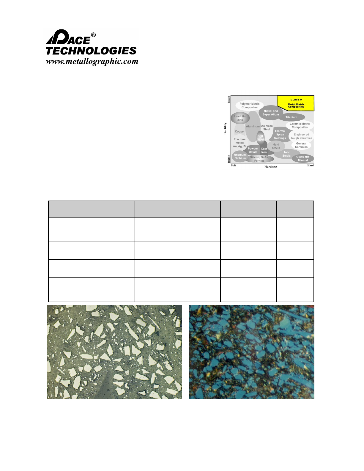
NANO 1000T / FEMTO 1500
Polishing Head
- - - - - - - - - - - - - - - - - - - - - - - - - - - - - - - - - - - - - - - - - - - - - - - - - - ▲ INSTRUCTION MANUAL
3601 E. 34th St. Tucson, AZ 85713 USA Tel. +1 520-882-6598 Fax +1 520-882-6599 email: pace@metallographic.com Web: http://www.metallographic.com
CLASS 9 Polishing Procedures
5.11.9 Metal Matrix Composites
Hard particles in a metal matrix can be difficult to prepare
because of particle pull-out as well as excessive relief between
the particles and the matrix. The key to preparation of metal
matrix composites (MMC) is to minimize damage at each
preparation stage. This includes sectioning with the appropriate
diamond wafering blade and using the finest practical abrasive
for initial grinding. Polishing with SIAMAT colloidal silica provides
a chemical mechanical polishing (CMP) action which is the most
effective means for eliminating both surface and subsurface damage. The combination of SIAMAT
colloidal silica with DIAMAT polycrystalline diamond also produces the required surfaces finishes in a
minimal amount of time.
Abrasive/surface Lubricant
30 um DIAMAT diamond
suspension on CERMESH Metal
Mesh cloth
9 um DIAMAT diamond on
POLYPAD polishing pad
3 um DIAMAT diamond on
TEXPAN polishing pad
0.05 micron NANOMETER
alumina on TRICOTE polishing
pad
5-10 lbs 200/200 rpm Until plane
5-10 lbs 200/200 rpm 3 minutes
SIAMAT
colloidal silica
5-10 lbs 100/100 rpm 1 minute
FEMTO pressure
setting (psi)
5-10 lbs 200/200 rpm 3 minutes
Head / Wheel speed Time
SiC particles in an Aluminum Matrix, 400X (DIC)
Please read this instruction manual carefully and follow all installation, operating and safety guidelines.
Zirconium Diboride particles in a Titanium Matrix
Etched, 1000X (DIC)
44
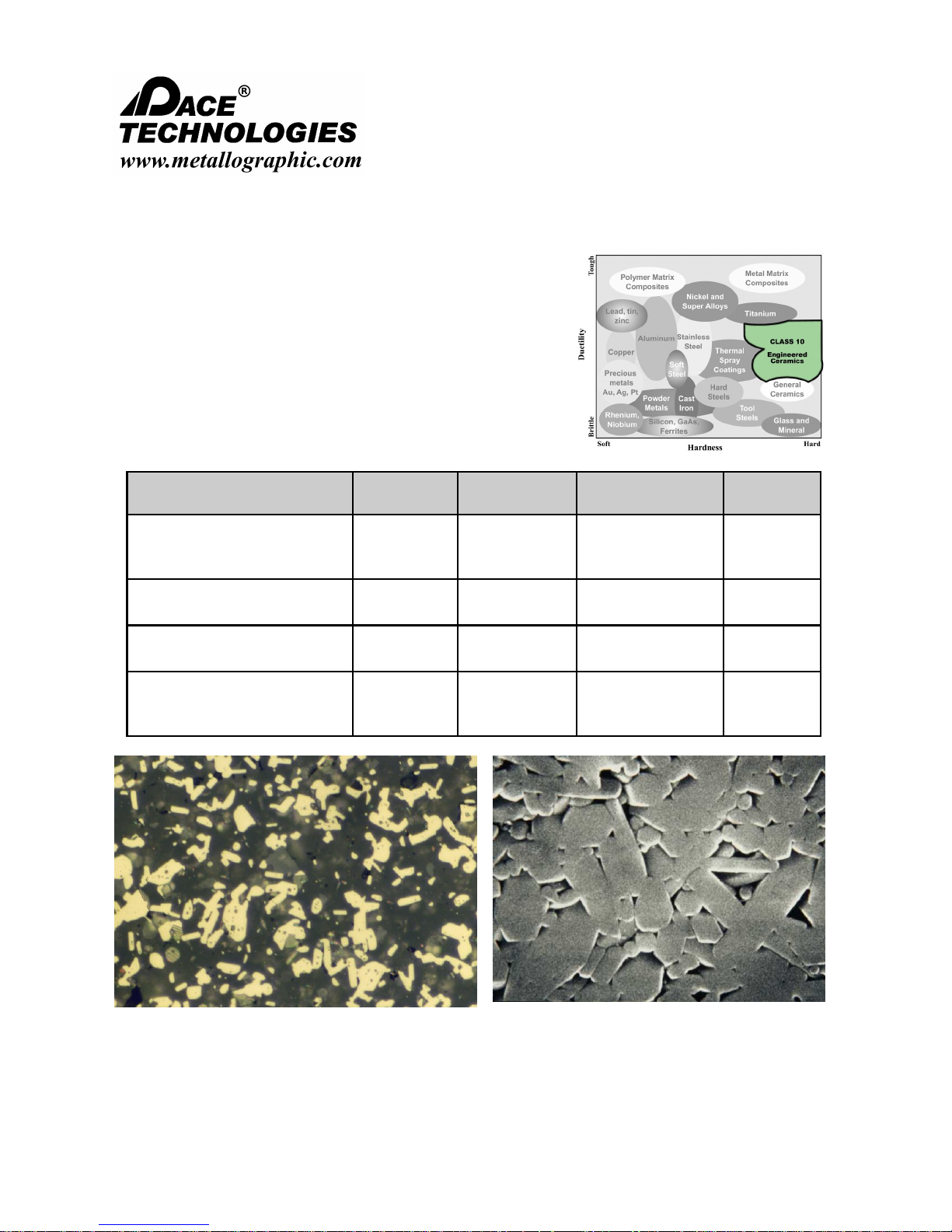
NANO 1000T / FEMTO 1500
Polishing Head
- - - - - - - - - - - - - - - - - - - - - - - - - - - - - - - - - - - - - - - - - - - - - - - - - - ▲ INSTRUCTION MANUAL
3601 E. 34th St. Tucson, AZ 85713 USA Tel. +1 520-882-6598 Fax +1 520-882-6599 email: pace@metallographic.com Web: http://www.metallographic.com
CLASS 10 Polishing Procedures
5.11.10 Engineered Ceramics
Engineered ceramics have found increasing applications for high
temperature, corrosion resistance, low wearability and a number of
other applications. An example of a Class 10 specimen preparation
technique is for aluminum oxynitride (AlON) which is a ceramic
composed of aluminum, oxygen and nitrogen. It is a transparent
ceramic that is harder than glass.
Abrasive/surface Lubricant
30 um DIAMAT diamond
suspension on CERMESH Metal
Mesh cloth
9 um DIAMAT diamond on
POLYPAD polishing pad
3 um DIAMAT diamond on
TEXPAN polishing pad
0.05 micron NANOMETER
alumina on TRICOTE polishing
pad
5-10 lbs 200/200 rpm Until plane
5-10 lbs 200/200 rpm 3 minutes
SIAMAT
colloidal silica
5-10 lbs 100/100 rpm 1 minute
FEMTO pressure
setting (psi)
5-10 lbs 200/200 rpm 3 minutes
Head / Wheel speed Time
AlON ceramic, B.F. 1000X (as polished)
Please read this instruction manual carefully and follow all installation, operating and safety guidelines.
SiAlON ceramic, etched in molten KOH, Mag 20K X
45
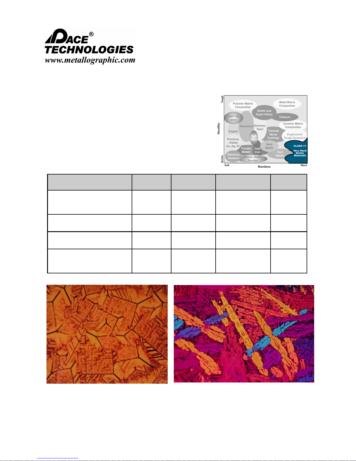
NANO 1000T / FEMTO 1500
Polishing Head
- - - - - - - - - - - - - - - - - - - - - - - - - - - - - - - - - - - - - - - - - - - - - - - - - - ▲ INSTRUCTION MANUAL
3601 E. 34th St. Tucson, AZ 85713 USA Tel. +1 520-882-6598 Fax +1 520-882-6599 email: pace@metallographic.com Web: http://www.metallographic.com
CLASS 11 Polishing Procedures
5.11.11 Glass and Minerals
Glasses and minerals are generally fairly hard and have a tendency
to fracture. Proper specimen preparation requires that the damage
during specimen preparation be minimized, even as early as the
sectioning or cutting operation.
Abrasive/surface Lubricant
30 um DIAMAT diamond
suspension on CERMESH Metal
Mesh cloth
9 um DIAMAT diamond on
POLYPAD polishing pad
3 um DIAMAT diamond on
TEXPAN polishing pad
0.05 micron NANOMETER
alumina on TRICOTE polishing
pad
5-10 lbs 200/200 rpm Until plane
5-10 lbs 200/200 rpm 3 minutes
SIAMAT
colloidal silica
5-10 lbs 100/100 rpm 1 minute
FEMTO pressure
setting (psi)
5-10 lbs 200/200 rpm 3 minutes
Head / Wheel speed Time
Alumino-silicate glass ceramic, 400X (Polarized
light) as polished
Please read this instruction manual carefully and follow all installation, operating and safety guidelines.
Slag, 100X (Polarized light), as polished condition
46

NANO 1000T / FEMTO 1500
Polishing Head
- - - - - - - - - - - - - - - - - - - - - - - - - - - - - - - - - - - - - - - - - - - - - - - - - - ▲ INSTRUCTION MANUAL
3601 E. 34th St. Tucson, AZ 85713 USA Tel. +1 520-882-6598 Fax +1 520-882-6599 email: pace@metallographic.com Web: http://www.metallographic.com
6.0 Maintenance
6.1 Introduction
The FEMTO 1500 requires very minimal maintenance. However, to increase the life of the
polisher, it is suggested that the unit be rinsed after use.
6.2 Cleaning outside cabinet
The cabinet should be cleaned occasionally with a moistened cloth. Do not use any chemicals
or cleaning abrasives.
Please read this instruction manual carefully and follow all installation, operating and safety guidelines.
47
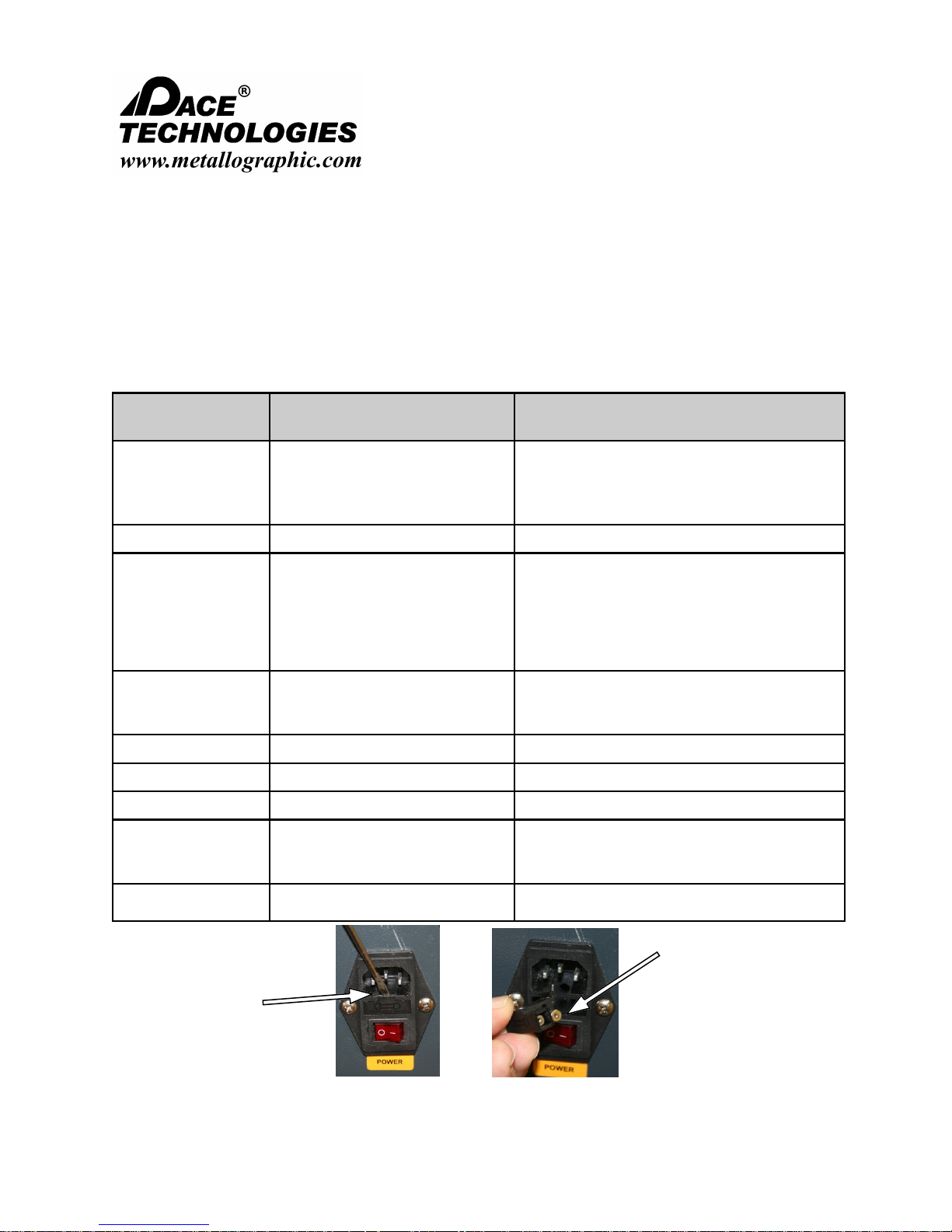
NANO 1000T / FEMTO 1500
Polishing Head
- - - - - - - - - - - - - - - - - - - - - - - - - - - - - - - - - - - - - - - - - - - - - - - - - - ▲ INSTRUCTION MANUAL
3601 E. 34th St. Tucson, AZ 85713 USA Tel. +1 520-882-6598 Fax +1 520-882-6599 email: pace@metallographic.com Web: http://www.metallographic.com
7.0 Troubleshooting
More extensive troubleshooting, repair guides, video’s, parts list are provided
online at www.metallographic.com or
http://www.metallographic.com/PACE-service/FEMTO-1100-service.html
Problem Cause Solution
No power or function a. Unit is disconnected from main
electrical power supply
b. Main power switch is off
c. Blown fuse
No air supply a. Air regulator blocked a. Clean air connections
Specimens not
polished evenly
across sample
Error Message E01 a. IPM protection produced by
Error Message E03 a. EEPROM error a. Replace board
Error Message E05 a. Over / under voltage a. Replace power supply
Error Message E06 a. Communications error a. Check for loose connector or bad cable
Error Message EOF a. Motor overheating a. Confirm proper voltage wiring set-up on
EOE a. Other errors a. Contact PACE Technologies for service
a. Specimen not breaking down
grinding paper uniformly
b. Relative velocity of base and
head does not match
motor power surge
a. Verify electrical source and
connection
b. Turn on main power switch
c. Replace fuse
a. Position specimen holder so that the
specimen tracks over the entire radius of
the grinding paper
b. Match head and base speed
a. Turn polisher off and wait until LED
discharges. Turn unit back on, if problem
persist contact PACE service department
motor.
b. Reduce applied force during grinding
Pry open fuse holder
with small flat head
screwdriver
Please read this instruction manual carefully and follow all installation, operating and safety guidelines.
Replace fuse
48

NANO 1000T / FEMTO 1500
Polishing Head
- - - - - - - - - - - - - - - - - - - - - - - - - - - - - - - - - - - - - - - - - - - - - - - - - - ▲ INSTRUCTION MANUAL
3601 E. 34th St. Tucson, AZ 85713 USA Tel. +1 520-882-6598 Fax +1 520-882-6599 email: pace@metallographic.com Web: http://www.metallographic.com
8.0 Metallographic Consumables
8.1 SiC Abrasive Paper, Surface Roughness
60-grit SiC
240-grit SiC
400-grit SiC
2-dimensional line profile 3-D optical contour mapping
600-grit SiC
1200-grit SiC
Please read this instruction manual carefully and follow all installation, operating and safety guidelines.
49
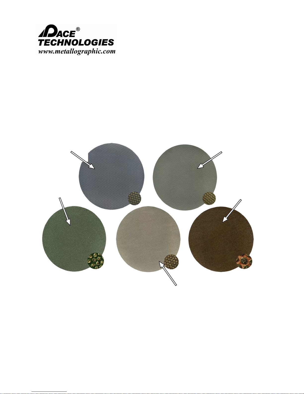
NANO 1000T / FEMTO 1500
Polishing Head
- - - - - - - - - - - - - - - - - - - - - - - - - - - - - - - - - - - - - - - - - - - - - - - - - - ▲ INSTRUCTION MANUAL
3601 E. 34th St. Tucson, AZ 85713 USA Tel. +1 520-882-6598 Fax +1 520-882-6599 email: pace@metallographic.com Web: http://www.metallographic.com
8.2 Diamond Grinding Disks
Diamond grinding is the most useful for removing material from ceramics and ceramic matrix composites. It is
also useful for hard non-ferrous metals such as titanium and zirconium. Diamond Grinding Disks are available in
9, 15, 30, 45, 70, 125 and 250 micron grit sizes.
In general, for grinding other ferrous, steel and softer non-ferrous metals, diamond is typically not the best
choice from both a performance and cost perspective.
9 micron Diamond
Disk
75 micron
Diamond Disk
Fixed Diamond Grinding Disks with Close-up
15 micron Diamond
Disk
250 micron
Diamond Disk
125 micron
Diamond Disk
Please read this instruction manual carefully and follow all installation, operating and safety guidelines.
50
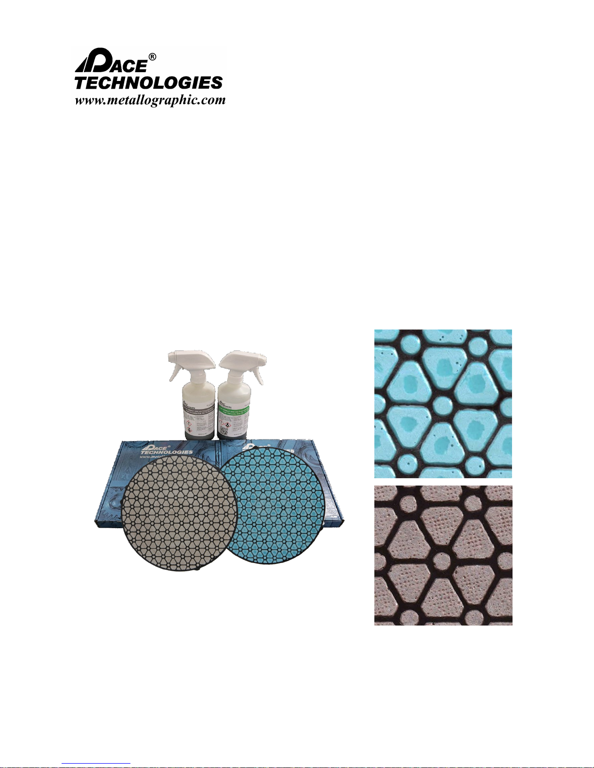
NANO 1000T / FEMTO 1500
Polishing Head
- - - - - - - - - - - - - - - - - - - - - - - - - - - - - - - - - - - - - - - - - - - - - - - - - - ▲ INSTRUCTION MANUAL
3601 E. 34th St. Tucson, AZ 85713 USA Tel. +1 520-882-6598 Fax +1 520-882-6599 email: pace@metallographic.com Web: http://www.metallographic.com
8.3 Composite Grinding Plates
Composite grinding disks are an alternative to intermediate grinding and polishing. PACE
Technologies composite disk vary slightly from other competitive products in that they are pre-charged
with diamond. This allows the disks to cut faster and longer. Two disks types are available, the ORION
composite polishing disk is pre-charged with 3 micron diamond, whereas the SIRIUS composite disk is
pre-charged with 9 micron diamond.
The SIRIUS composites grinding disks offer an alternative to grinding with 320-600 grit SiC
papers, and the ORION composite disk offer an excellent alternative to rough polishing with 3-6
micron diamond.
Composite grinding disks using diamond suspensions.
Please read this instruction manual carefully and follow all installation, operating and safety guidelines.
Composite grinding disks close-up
51
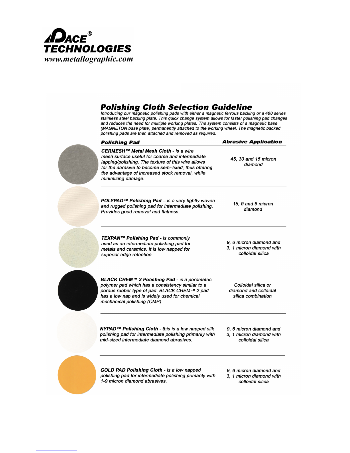
NANO 1000T / FEMTO 1500
Polishing Head
- - - - - - - - - - - - - - - - - - - - - - - - - - - - - - - - - - - - - - - - - - - - - - - - - - ▲ INSTRUCTION MANUAL
3601 E. 34th St. Tucson, AZ 85713 USA Tel. +1 520-882-6598 Fax +1 520-882-6599 email: pace@metallographic.com Web: http://www.metallographic.com
8.4 Polishing Pads
Please read this instruction manual carefully and follow all installation, operating and safety guidelines.
52

NANO 1000T / FEMTO 1500
Polishing Head
- - - - - - - - - - - - - - - - - - - - - - - - - - - - - - - - - - - - - - - - - - - - - - - - - - ▲ INSTRUCTION MANUAL
3601 E. 34th St. Tucson, AZ 85713 USA Tel. +1 520-882-6598 Fax +1 520-882-6599 email: pace@metallographic.com Web: http://www.metallographic.com
8.4 Polishing Pads
Please read this instruction manual carefully and follow all installation, operating and safety guidelines.
53
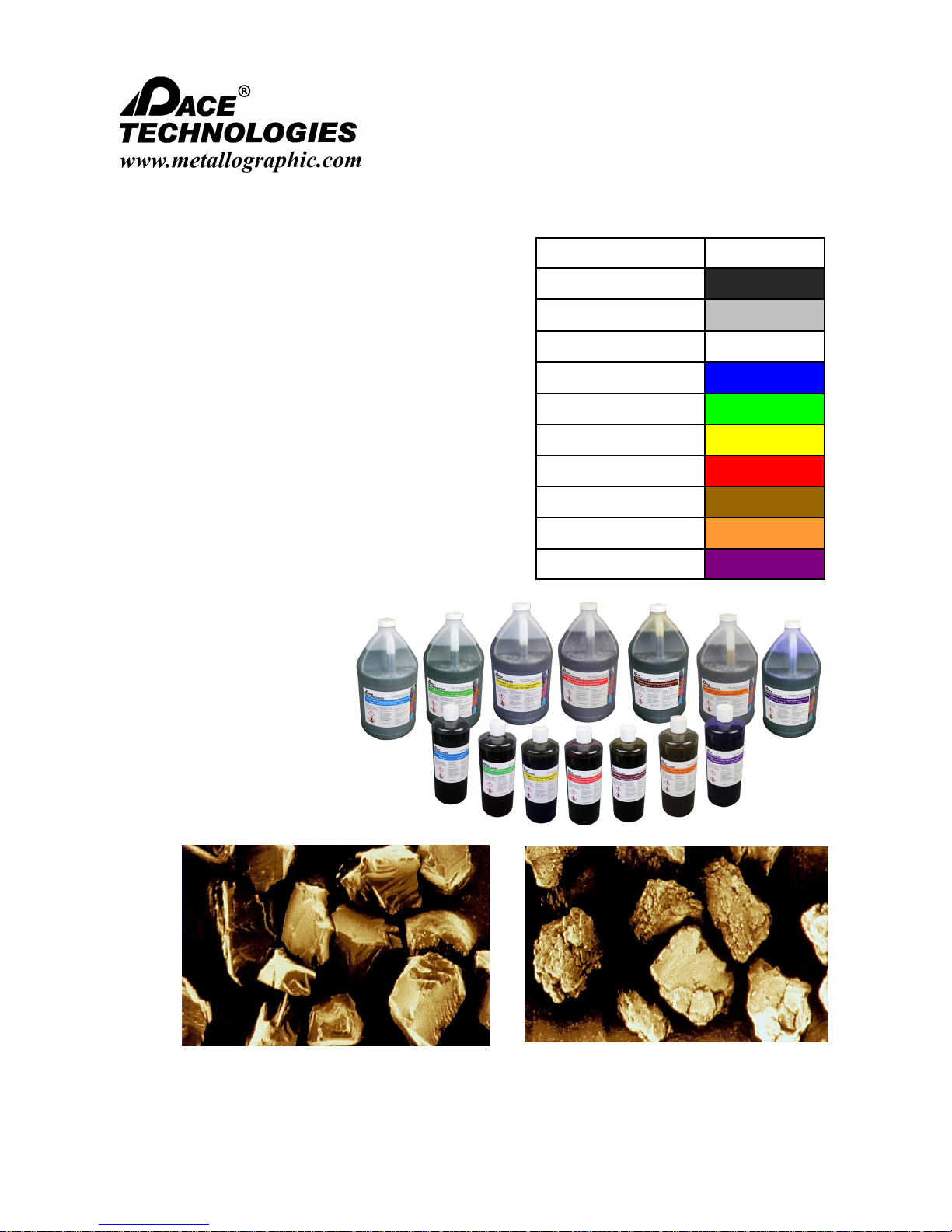
NANO 1000T / FEMTO 1500
Polishing Head
- - - - - - - - - - - - - - - - - - - - - - - - - - - - - - - - - - - - - - - - - - - - - - - - - - ▲ INSTRUCTION MANUAL
3601 E. 34th St. Tucson, AZ 85713 USA Tel. +1 520-882-6598 Fax +1 520-882-6599 email: pace@metallographic.com Web: http://www.metallographic.com
8.5 Polycrystalline Diamond Abrasives
Polycrystalline diamond is a synthetic diamond which
provides better surface finishes and higher removal rates
than monocrystalline diamond. The following are the
advantages of a polycrystalline diamond over a
monocrystalline diamond:
Higher removal rates (self-sharpening abrasive)
Very uniform surface finish
More uniform particle size distribution
Harder / tougher particles
Blocky - shaped particles
Hexagonal (equally hard in all directions)
microcrystallites
Extremely rough surface (more cutting points)
Surface area is 300% greater than with a
monocrystalline diamond
No abrasion-resistant
directionality (abrasion
Diamond Size (um) Color code
0.10
0.25
0.50
1.0
3.0
6.0
9.0
15
30
45
Charcoal
Gray
White
Blue
Green
Yellow
Red
Brown
Orange
Purple
Monocrystalline blocky - diamond
Please read this instruction manual carefully and follow all installation, operating and safety guidelines.
Polycrystalline multi-faceted diamond
54

NANO 1000T / FEMTO 1500
Polishing Head
- - - - - - - - - - - - - - - - - - - - - - - - - - - - - - - - - - - - - - - - - - - - - - - - - - ▲ INSTRUCTION MANUAL
3601 E. 34th St. Tucson, AZ 85713 USA Tel. +1 520-882-6598 Fax +1 520-882-6599 email: pace@metallographic.com Web: http://www.metallographic.com
8.6 Final Polishing Abrasives
Final polishing abrasives include fine diamond, alumina
and colloidal silica. For successful microstructural preparation, the polishing abrasive / cloth
combination must be appropriately matched to the specimen hardness, fracture toughness and
corrosion properties of the specimen.
Colloidal Silica
Colloidal silica is a relatively soft abrasive with high chemical activity. It is an ideal chemical
mechanical polishing (CMP) abrasive. The chemical activity of colloidal silica results from the
electrochemical balance (zeta potential) required to keep very fine particles from aggregating. This
chemical balance also produces a surface phenomenon which makes the specimen surface more
chemically active. This produces a surface layer which can be mechanically removed by the colloidal
silica particles themselves, or by the mechanical scrubbing of the surface with the polishing pad.
For ceramics, the combination of fine polycrystalline diamond and colloidal silica improves surface
finishes and increases polishing rates.
Nanometer Alumina
Nanometer alumina is a polycrystalline colloidal alumina processed by a proprietary seeded gell
process. Polycrystalline alumina offers two significant improvements over conventional alumina
calcining processes:
1. Tighter, more controlled particle size distributions
2. Harder alpha alumina particles
The tighter, more controlled particle size distribution is a result of less particle aggregation which
produces significantly less scratching in soft metals, such as aluminum, tin, lead, copper and soft
steels.
Please read this instruction manual carefully and follow all installation, operating and safety guidelines.
55

NANO 1000T / FEMTO 1500
Polishing Head
- - - - - - - - - - - - - - - - - - - - - - - - - - - - - - - - - - - - - - - - - - - - - - - - - - ▲ INSTRUCTION MANUAL
3601 E. 34th St. Tucson, AZ 85713 USA Tel. +1 520-882-6598 Fax +1 520-882-6599 email: pace@metallographic.com Web: http://www.metallographic.com
9.0 Spare Parts
Part no. Description Image
Electrical
FM-001
FM-001-C
FM-002
FM-48V
Front Panel PC board Controller
PC board communication cable
FEMTO 1100 speed control board
FEMTO 1100 48V power supply
FM-100
P150-217
Please read this instruction manual carefully and follow all installation, operating and safety guidelines.
Power distribution box
Speed sensor
56

NANO 1000T / FEMTO 1500
Polishing Head
- - - - - - - - - - - - - - - - - - - - - - - - - - - - - - - - - - - - - - - - - - - - - - - - - - ▲ INSTRUCTION MANUAL
3601 E. 34th St. Tucson, AZ 85713 USA Tel. +1 520-882-6598 Fax +1 520-882-6599 email: pace@metallographic.com Web: http://www.metallographic.com
Part no. Description Image
Electrical
FM-006
FM-013
FM-014
FM-015
FEMTO 1100 Motor and gear box (125 W)
FEMTO 1100 Power cable to NANO base
(Female to Female)
FEMTO 1100 Communication cable NANO
1000T (short)
FEMTO 1100 Communication cable NANO
2000 (long)
FAN-24V
TP1-E-FC
Please read this instruction manual carefully and follow all installation, operating and safety guidelines.
24 V Fan
Fan cover plate
57

NANO 1000T / FEMTO 1500
Polishing Head
- - - - - - - - - - - - - - - - - - - - - - - - - - - - - - - - - - - - - - - - - - - - - - - - - - ▲ INSTRUCTION MANUAL
3601 E. 34th St. Tucson, AZ 85713 USA Tel. +1 520-882-6598 Fax +1 520-882-6599 email: pace@metallographic.com Web: http://www.metallographic.com
Part no. Description Image
Electrical
24RELAY
RELAY-B
FEMTO-R
PS-001
FUSE-6A
24 volt relay switch
24 volt relay switch base
Rectifier
TP-7000/ TP-7001 ON/OFF power switch
6 amp fast blowing fuse (3/pkg)
Part no. Description Image
Electrical
FM-025
FM-16
Please read this instruction manual carefully and follow all installation, operating and safety guidelines.
Polychain belt (OP-355M)
FEMTO Dispenser unit (gravity feed)
58
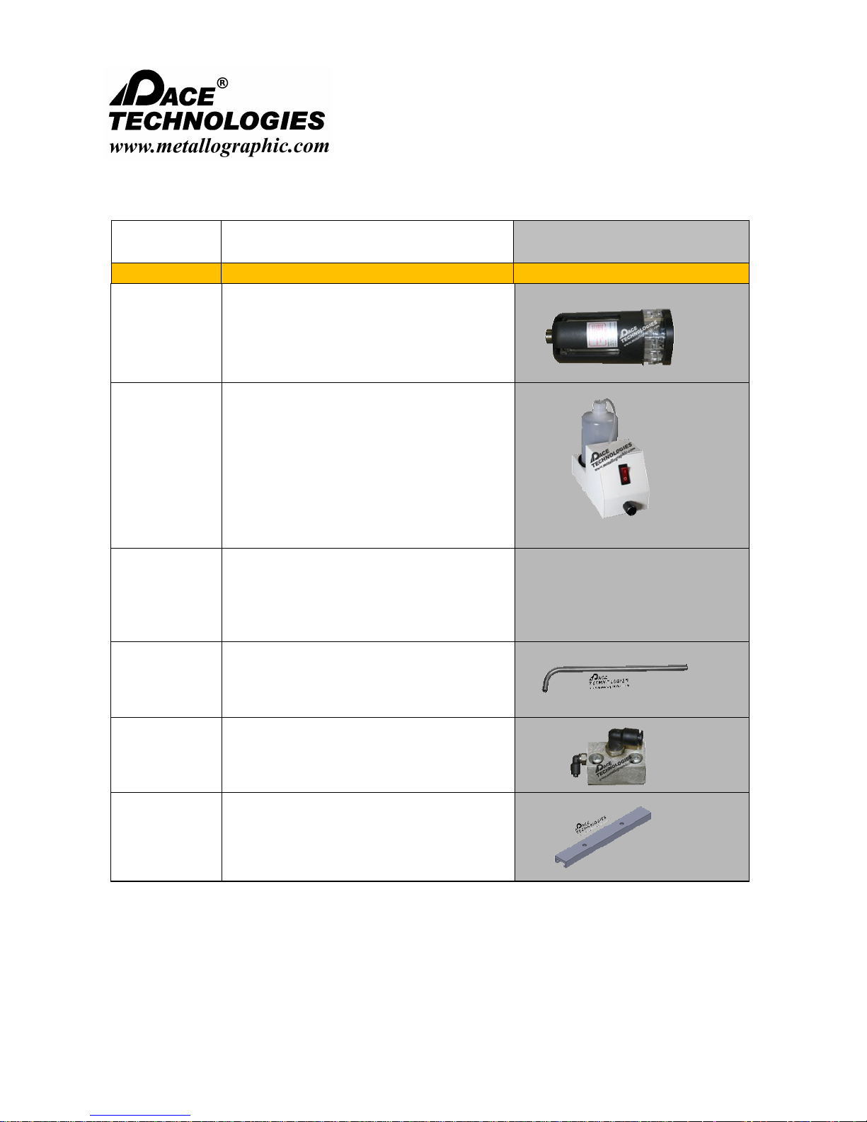
NANO 1000T / FEMTO 1500
Polishing Head
- - - - - - - - - - - - - - - - - - - - - - - - - - - - - - - - - - - - - - - - - - - - - - - - - - ▲ INSTRUCTION MANUAL
3601 E. 34th St. Tucson, AZ 85713 USA Tel. +1 520-882-6598 Fax +1 520-882-6599 email: pace@metallographic.com Web: http://www.metallographic.com
Part no. Description Image
Mechanical Parts
LUB-1000
FM-PUMP
FM-TUBE
FM-018
FEMTO Dispenser bottle
FEMTO 1100 Dispenser unit with pump
FEMTO 1100 pump dispenser tubing
FEMTO Dispenser stainless steel tube
FM-017
FM-M-031
Please read this instruction manual carefully and follow all installation, operating and safety guidelines.
FEMTO Dispenser distribution block
Sliding guide for lubrication dispenser
block
59
NANO 1000T / FEMTO 1500
Polishing Head
- - - - - - - - - - - - - - - - - - - - - - - - - - - - - - - - - - - - - - - - - - - - - - - - - - ▲ INSTRUCTION MANUAL
3601 E. 34th St. Tucson, AZ 85713 USA Tel. +1 520-882-6598 Fax +1 520-882-6599 email: pace@metallographic.com Web: http://www.metallographic.com
Part no. Description Image
Mechanical Parts
FM-007
FM-010
FM-010-H
FM-011
FEMTO 1100 FRP cover
FEMTO 1000 Locking lever
FEMTO 1100 Lifting Handle
FEMTO 1000 Height adjustment collar
FM-012
FM-M-
APL
FM-1100T
Please read this instruction manual carefully and follow all installation, operating and safety guidelines.
FEMTO post-actuator
FEMTO 1100 aluminum plate
FEMTO 1100 Template
60

NANO 1000T / FEMTO 1500
Polishing Head
- - - - - - - - - - - - - - - - - - - - - - - - - - - - - - - - - - - - - - - - - - - - - - - - - - ▲ INSTRUCTION MANUAL
3601 E. 34th St. Tucson, AZ 85713 USA Tel. +1 520-882-6598 Fax +1 520-882-6599 email: pace@metallographic.com Web: http://www.metallographic.com
Part no. Description Image
Mechanical Parts
FM-M-020
FM-M-021
FM-M-023-2
FM-M-024
Air-cylinder-bracket
Air-Distributor-bracket
Arbor-holder
Base
FM-M-025
FM-M-026
Please read this instruction manual carefully and follow all installation, operating and safety guidelines.
Base flange
Main-shaft-plastic-ring
61
NANO 1000T / FEMTO 1500
Polishing Head
- - - - - - - - - - - - - - - - - - - - - - - - - - - - - - - - - - - - - - - - - - - - - - - - - - ▲ INSTRUCTION MANUAL
3601 E. 34th St. Tucson, AZ 85713 USA Tel. +1 520-882-6598 Fax +1 520-882-6599 email: pace@metallographic.com Web: http://www.metallographic.com
Part no. Description Image
Mechanical Parts
FM-M-028
FM-M-029
FM-M-030
FM-M-023-1
Collar adapter
Head gear
Motor gear
Motor mounting block
FM-M-032
FM-M-PRH
FM-M-HTCP
Please read this instruction manual carefully and follow all installation, operating and safety guidelines.
Small cylinder holder
Piston rod housing
Housing top cover plate
62
NANO 1000T / FEMTO 1500
Polishing Head
- - - - - - - - - - - - - - - - - - - - - - - - - - - - - - - - - - - - - - - - - - - - - - - - - - ▲ INSTRUCTION MANUAL
3601 E. 34th St. Tucson, AZ 85713 USA Tel. +1 520-882-6598 Fax +1 520-882-6599 email: pace@metallographic.com Web: http://www.metallographic.com
Part no. Description Image
Pneumatic Parts
FM-003
FM-004
FM-005
FM-021
FM-009
FEMTO 1100 Piston cylinders (each)
FEMTO 1100 Rubber boot (each)
FEMTO 1100 stainless steel pressure
shoe (plate)
Pressure control valve
Pressure release valve for lifting head
AR-001
AP-002
Please read this instruction manual carefully and follow all installation, operating and safety guidelines.
Air regulator
Pressure guage
63
NANO 1000T / FEMTO 1500
Polishing Head
- - - - - - - - - - - - - - - - - - - - - - - - - - - - - - - - - - - - - - - - - - - - - - - - - - ▲ INSTRUCTION MANUAL
3601 E. 34th St. Tucson, AZ 85713 USA Tel. +1 520-882-6598 Fax +1 520-882-6599 email: pace@metallographic.com Web: http://www.metallographic.com
Part no. Description Image
Pneumatic Parts
AH-6MM
AH-6MM
TP-AIR
AIR-0100
Specimen Holders
6 mm air hose (2 meters)
6 mm diameter air hose connector
Air hose connector (2-sided)
Air filter lubricator
FM-008
SH-1100
SH-1200
Please read this instruction manual carefully and follow all installation, operating and safety guidelines.
FEMTO 1100 Coupler
Specimen holder for 1-6 samples (2540 mm and 1-1.5-inch specimen rings)
Specimen holder for 1-3 samples (50
mm and 2-inch specimen rings)
64
NANO 1000T / FEMTO 1500
Polishing Head
- - - - - - - - - - - - - - - - - - - - - - - - - - - - - - - - - - - - - - - - - - - - - - - - - - ▲ INSTRUCTION MANUAL
3601 E. 34th St. Tucson, AZ 85713 USA Tel. +1 520-882-6598 Fax +1 520-882-6599 email: pace@metallographic.com Web: http://www.metallographic.com
Part no. Description Image
Specimen Holders
SR-0100
SR-0125
SR-0150
SR-0200
SR-25mm
1-inch specimen rings (6/set)
1.25-inch specimen rings (6/set)
1.5-inch specimen rings (6/set)
2-inch specimen rings (3/set)
25 mm specimen rings (6/set)
SR-30mm
SR-40mm
SR-50mm
Please read this instruction manual carefully and follow all installation, operating and safety guidelines.
30 mm specimen rings (6/set)
40 mm specimen rings (6/set)
50 mm specimen rings (3/set)
65
NANO 1000T / FEMTO 1500
Polishing Head
- - - - - - - - - - - - - - - - - - - - - - - - - - - - - - - - - - - - - - - - - - - - - - - - - - ▲ INSTRUCTION MANUAL
3601 E. 34th St. Tucson, AZ 85713 USA Tel. +1 520-882-6598 Fax +1 520-882-6599 email: pace@metallographic.com Web: http://www.metallographic.com
Part no. Description Images
N1-007b
N1-007c
N1-008b
Electrical (NANO)
NANO 1000T and 2000T Motor
(750 W - 1 hp)
NANO 1200T Motor (1.5 hp)
NANO 1000T/2000T PC board /
frequency convertor (new machine using
24V transformer)
NANO 1200T PC board / frequency
N1-008c
N1-008T
Please read this instruction manual carefully and follow all installation, operating and safety guidelines.
convertor (new machine using 24V
transformer)
PC board (top only) for 1 rpm increments
66
NANO 1000T / FEMTO 1500
Polishing Head
- - - - - - - - - - - - - - - - - - - - - - - - - - - - - - - - - - - - - - - - - - - - - - - - - - ▲ INSTRUCTION MANUAL
3601 E. 34th St. Tucson, AZ 85713 USA Tel. +1 520-882-6598 Fax +1 520-882-6599 email: pace@metallographic.com Web: http://www.metallographic.com
Part no. Description Images
N1-012b
N1-013
N1-015b
N1-015c
FUSE-C
Electrical (NANO)
Transformer (24V)
Emergency Stop
Front Panel (with time display) with PC
board
Front panel connection cable (with time
display)
Controller T6.3A fuse - (each)
FUSE-NA
PS-001
24RELAY
Please read this instruction manual carefully and follow all installation, operating and safety guidelines.
10 amp fuse for NANO Polishers (3/
package)
On/Off switch
24 volt relay switch
67
NANO 1000T / FEMTO 1500
Polishing Head
- - - - - - - - - - - - - - - - - - - - - - - - - - - - - - - - - - - - - - - - - - - - - - - - - - ▲ INSTRUCTION MANUAL
3601 E. 34th St. Tucson, AZ 85713 USA Tel. +1 520-882-6598 Fax +1 520-882-6599 email: pace@metallographic.com Web: http://www.metallographic.com
Part no. Description Images
RELAY-B
NANO-R
N1-009b
CORD-110V
Electrical (NANO)
24 volt relay switch base
Rectifier
Solenoid Valve (24 V)
110V power cord
CORD-220R
CORD-220F
Please read this instruction manual carefully and follow all installation, operating and safety guidelines.
220V round time power cord
220V three prop flat connector
68

NANO 1000T / FEMTO 1500
Polishing Head
- - - - - - - - - - - - - - - - - - - - - - - - - - - - - - - - - - - - - - - - - - - - - - - - - - ▲ INSTRUCTION MANUAL
3601 E. 34th St. Tucson, AZ 85713 USA Tel. +1 520-882-6598 Fax +1 520-882-6599 email: pace@metallographic.com Web: http://www.metallographic.com
Part no. Description Images
PW-800
PW-1000
PW-1200 NANO 1200 12-inch working wheel
PW-1400 NANO 1200 14-inch working wheel
N1-001
N2-001
Mechanical Components (NANO)
NANO 1000T-2000 8-inch working
wheel
NANO 1000T-2000 10-inch working
wheel
NANO 1000T Single Wheel FRP cover
NANO 2000 Double Wheel FRP cover
N12-001
N1-002
Please read this instruction manual carefully and follow all installation, operating and safety guidelines.
NANO 1200 FRP cover
NANO 1000T-2000 Polishing Table
Support Platen
69

NANO 1000T / FEMTO 1500
Polishing Head
- - - - - - - - - - - - - - - - - - - - - - - - - - - - - - - - - - - - - - - - - - - - - - - - - - ▲ INSTRUCTION MANUAL
3601 E. 34th St. Tucson, AZ 85713 USA Tel. +1 520-882-6598 Fax +1 520-882-6599 email: pace@metallographic.com Web: http://www.metallographic.com
Part no. Description Images
N12-002
N1-002PEG
N1-002-O-Ring
N1-003S
Mechanical Components (NANO)
NANO 1200 Polishing Table Support
Platen
Table support PEG's without o-rings
(3/set)
Table support PEG O-ring (3/pkg)
NANO 1000TT/2000T Spindle assembly
N1-025
N1-003P
N1-006
Please read this instruction manual carefully and follow all installation, operating and safety guidelines.
FEMTO 1100 post collar (mounts on the
NANO 1000T-2000 polisher)
NANO 1000T-2000 Pulley wheel for
spindle wheel
NANO 1000T-2000 Pulley for motor
70

NANO 1000T / FEMTO 1500
Polishing Head
- - - - - - - - - - - - - - - - - - - - - - - - - - - - - - - - - - - - - - - - - - - - - - - - - - ▲ INSTRUCTION MANUAL
3601 E. 34th St. Tucson, AZ 85713 USA Tel. +1 520-882-6598 Fax +1 520-882-6599 email: pace@metallographic.com Web: http://www.metallographic.com
Part no. Description Images
N1-005
N2-005
N12-005
PTM-125-005
PTM-125-006
Mechanical Components (NANO)
NANO 1000T Single Wheel Belt
NANO 2000T Double Wheel Belt
NANO 1200T Single Wheel Belt
8-inch plain backed paper ring
10-inch plain backed paper ring
PTM-225-005
PTM-225-006
PTM-125-007
PTM-225-007
PTM-225-007H
Please read this instruction manual carefully and follow all installation, operating and safety guidelines.
12-inch plain backed paper ring
14-inch plain backed paper ring
8 and 10-inch polisher cover
12 and 14-inch polisher cover
Cover handle
71

NANO 1000T / FEMTO 1500
Polishing Head
- - - - - - - - - - - - - - - - - - - - - - - - - - - - - - - - - - - - - - - - - - - - - - - - - - ▲ INSTRUCTION MANUAL
3601 E. 34th St. Tucson, AZ 85713 USA Tel. +1 520-882-6598 Fax +1 520-882-6599 email: pace@metallographic.com Web: http://www.metallographic.com
Part no. Description Images
PTM-125-001
PTM-125-207
FT-004
N1-T
Mechanical Components (NANO)
8 and 10-inch splash guard
12 and 14-inch splash guard
Feet (4/pkg)
NANO 1000T Template
N2-T
N12-T
N1-M-001
Please read this instruction manual carefully and follow all installation, operating and safety guidelines.
NANO 2000T Template
NANO 1200T Template
NANO 1000 Casting
72

NANO 1000T / FEMTO 1500
Polishing Head
- - - - - - - - - - - - - - - - - - - - - - - - - - - - - - - - - - - - - - - - - - - - - - - - - - ▲ INSTRUCTION MANUAL
3601 E. 34th St. Tucson, AZ 85713 USA Tel. +1 520-882-6598 Fax +1 520-882-6599 email: pace@metallographic.com Web: http://www.metallographic.com
Part no. Description Images
N2-M-001
N12-M-001
N1-M-002
N1-M-003
Mechanical Components (NANO)
NANO 2000 casting
N1200 casting
Plastic cover
FEMTO slot holder
N1-M-004
N2-P-BC
Please read this instruction manual carefully and follow all installation, operating and safety guidelines.
NANO 1000 Bottom cover
NANO 2000 Bottom cover
73

NANO 1000T / FEMTO 1500
Polishing Head
- - - - - - - - - - - - - - - - - - - - - - - - - - - - - - - - - - - - - - - - - - - - - - - - - - ▲ INSTRUCTION MANUAL
3601 E. 34th St. Tucson, AZ 85713 USA Tel. +1 520-882-6598 Fax +1 520-882-6599 email: pace@metallographic.com Web: http://www.metallographic.com
Part no. Description Images
N12-BOT
N1-M-008
N2-M-003
N12-M-003
Mechanical Components (NANO)
NANO 1200 plastic bottom cover
NANO 1000T Motor holder
NANO 2000T Motor holder
NANO 1200 Motor holder
N1-014b
N2-M-002
Please read this instruction manual carefully and follow all installation, operating and safety guidelines.
NANO 1000 rear panel
NANO 2000 rear panel
74

NANO 1000T / FEMTO 1500
Polishing Head
- - - - - - - - - - - - - - - - - - - - - - - - - - - - - - - - - - - - - - - - - - - - - - - - - - ▲ INSTRUCTION MANUAL
3601 E. 34th St. Tucson, AZ 85713 USA Tel. +1 520-882-6598 Fax +1 520-882-6599 email: pace@metallographic.com Web: http://www.metallographic.com
Part no. Description Images
N12-BP
N1-M-007
N1-M-005
Mechanical Components (NANO)
NANO 1200 rear panel
Front Panel for NANO
1000T/1200T/2000T Polisher (each)
Solenoid bracket
N1-M-006
N1-M-009
Please read this instruction manual carefully and follow all installation, operating and safety guidelines.
Water adapter bracket
Water hose clamp
75

NANO 1000T / FEMTO 1500
Polishing Head
- - - - - - - - - - - - - - - - - - - - - - - - - - - - - - - - - - - - - - - - - - - - - - - - - - ▲ INSTRUCTION MANUAL
3601 E. 34th St. Tucson, AZ 85713 USA Tel. +1 520-882-6598 Fax +1 520-882-6599 email: pace@metallographic.com Web: http://www.metallographic.com
Part no. Description Images
N12-M-002
N12-M-004
N12-M-CR
N12-M-005
Mechanical Components (NANO)
NANO 1200 Spindle
NANO 1200 Wheel pulley
NANO 1200 copper ring
NANO 1200 Spindle shaft
N12-M-SSA
N12-M-RSH
Please read this instruction manual carefully and follow all installation, operating and safety guidelines.
NANO 1200 Spindle shaft adapter
NANO 1200 roller shaft housing
76
NANO 1000T / FEMTO 1500
Polishing Head
- - - - - - - - - - - - - - - - - - - - - - - - - - - - - - - - - - - - - - - - - - - - - - - - - - ▲ INSTRUCTION MANUAL
3601 E. 34th St. Tucson, AZ 85713 USA Tel. +1 520-882-6598 Fax +1 520-882-6599 email: pace@metallographic.com Web: http://www.metallographic.com
Part no. Description Images
W-6M
W-E-8MM
W-S-8MM
P-Drain
Plumbing Components (NANO)
6 mm diameter water supply hose
connector
Elbow 8mm quick water connector
8mm water split quick connector
Drain hose ( ~2 meters)
P-Inlet
N-P-CFA
N1-010
Please read this instruction manual carefully and follow all installation, operating and safety guidelines.
Water inlet hose (~2 meters)
Copper female adapter
Drain connector set (elbow, nipple, hose
barb)
77
NANO 1000T / FEMTO 1500
Polishing Head
- - - - - - - - - - - - - - - - - - - - - - - - - - - - - - - - - - - - - - - - - - - - - - - - - - ▲ INSTRUCTION MANUAL
3601 E. 34th St. Tucson, AZ 85713 USA Tel. +1 520-882-6598 Fax +1 520-882-6599 email: pace@metallographic.com Web: http://www.metallographic.com
Part no. Description Images
N2-009
D-REDUCER
D-ELBOW
D-NIPPLE
D-BARB
Plumbing Components (NANO)
NANO 2000 Drain T-fitting
Drain Reducer
Drain elbow
Drain-nipple
Drain hose barb
P-RINSE
P-ADAPTER
PVL
PVR
Please read this instruction manual carefully and follow all installation, operating and safety guidelines.
Rinse bowl water sprayer
Rinse bowl water connector
Water value (right side) - single unit and
right side double
Water value (left side) - double unit only
78
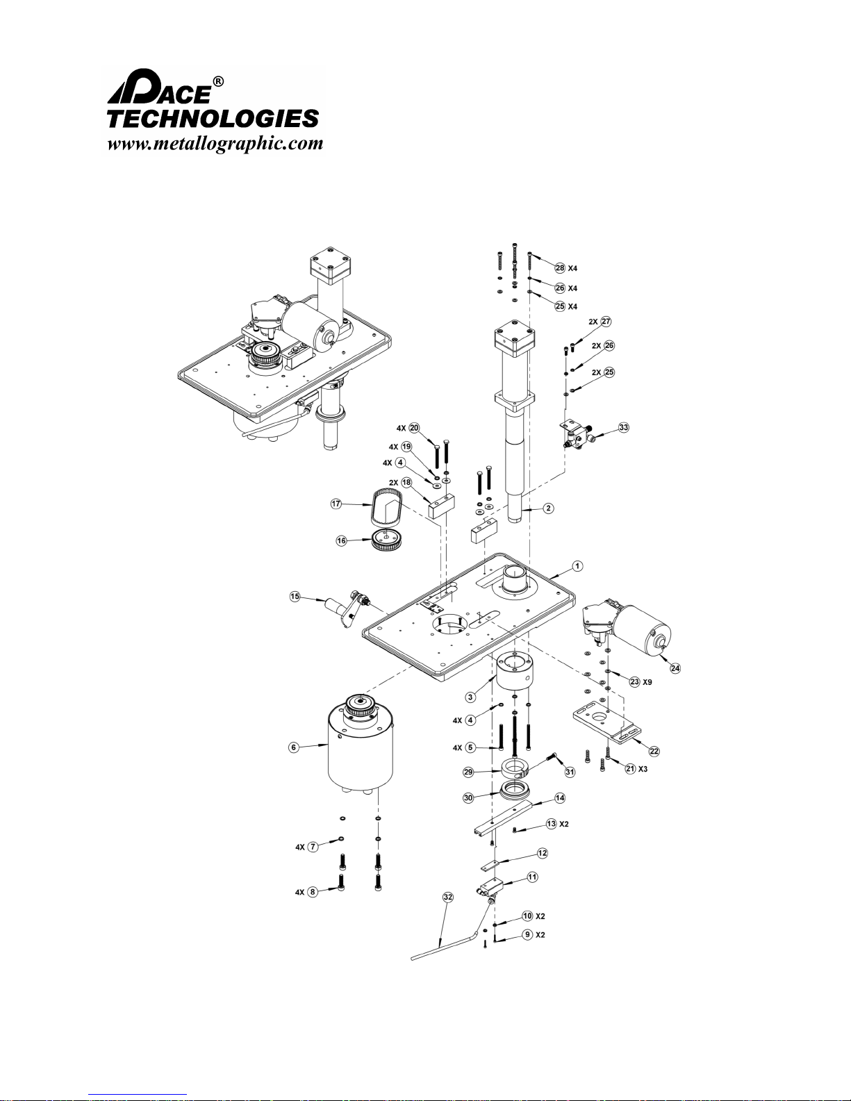
NANO 1000T / FEMTO 1500
Polishing Head
- - - - - - - - - - - - - - - - - - - - - - - - - - - - - - - - - - - - - - - - - - - - - - - - - - ▲ INSTRUCTION MANUAL
3601 E. 34th St. Tucson, AZ 85713 USA Tel. +1 520-882-6598 Fax +1 520-882-6599 email: pace@metallographic.com Web: http://www.metallographic.com
9.0 Schematics (FEMTO mechanical)
Please read this instruction manual carefully and follow all installation, operating and safety guidelines.
79

Item Part Number Description Total QTY
1 FM-M-024 FEMTO 1100 BASE 1
2 FM-012 FEMTO POST ACCUATOR 1
3 FM-M-028 COLLAR APAPTER 1
4 N/A LOCKING WASHER 7.25MM ID 8
5 N/A ALLEN BOLT (5MM ALLEN) 6MM X 1.0 X 60 4
6 N/A PISTON ASSEMBLY 1
7 N/A LOCKING WASHER 8.5MM ID 4
8 N/A ALLEN BOLT (6MM ALLEN) 8MM X 1.25 X 30 4
9 N/A ALLEN BOLT (2.5MM ALLEN) 3MM X 0.5 X 16 2
10 N/A LOCKING WASHER 5MM ID 2
11 N/A FEMTO DISPENSER DISTRIBUITION ASSEMBLY 1
12 N/A FEMTO SLIDING GUIDE MOUNTING TAB 1
13 N/A FLAT HEAD BOLT (PHILLIPS) 5MM X 0.8 X 10 2
14 FM-M-0 31 SLIDING GUIDE FOR LUBRICATION DISPENSER BLOCK 1
15 FM-010 FEMTO LOCKING LEVER ASSEMBLY 1
16 FM-M-0 30 MOTOR GEAR 1
17 FM-025 POLYCHAIN BELT (OP-355M) 1
18 FM-M-023-1 MOTOR MOUNTING BLOCK 2
19 N/A WASHER 6MM ID 18MM OD 4
20 N/A HEX HEAD BOLT 6MM X 1.00 X 60 4
21 N/A ALLEN BOLT (5MM ALLEN) 6MM X 1.0 X 24 3
22 FM-M-023-2 ARBOR HOLDER 1
23 N/A WASHER 6.25MM ID 12MM OD 9
24 FM-006 FEMTO 11 MOTOR AND GEAR BOX (125 W) 1
25 N/A WASHER 5.5MM ID 10MM OD 6
26 N/A LOCKING WASHER 5MM ID 6
27 N/A ALLEN BOLT (4MM ALLEN) 5MM X 0.8 X 14 2
28 N/A ALLEN BOLT (4MM ALLEN) 5MM X 0.8 X 40 4
29 FM-011 FEMTO HEIGHT ADJ USTMENT COLLAR 1
30 FM-M-0 26 MAIN SHAFT PLASTIC RING 1
31 N/A ALLEN BOLT (4MM ALLEN) 5MM X 0.8 X 20 1
32 FM-018 DISPENSER SS TUBE 1
NANO 1000T / FEMTO 1500
- - - - - - - - - - - - - - - - - - - - - - - - - - - - - - - - - - - - - - - - - - - - - - - - - - ▲ INSTRUCTION MANUAL
3601 E. 34th St. Tucson, AZ 85713 USA Tel. +1 520-882-6598 Fax +1 520-882-6599 email: pace@metallographic.com Web: http://www.metallographic.com
FEMTO 1500 Assembly (continued)
Please read this instruction manual carefully and follow all installation, operating and safety guidelines.
Polishing Head
80
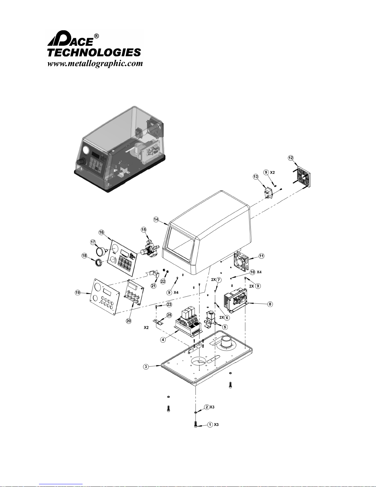
NANO 1000T / FEMTO 1500
Polishing Head
- - - - - - - - - - - - - - - - - - - - - - - - - - - - - - - - - - - - - - - - - - - - - - - - - - ▲ INSTRUCTION MANUAL
3601 E. 34th St. Tucson, AZ 85713 USA Tel. +1 520-882-6598 Fax +1 520-882-6599 email: pace@metallographic.com Web: http://www.metallographic.com
FEMTO 1500 Assembly Electrical - Exploded
Please read this instruction manual carefully and follow all installation, operating and safety guidelines.
81

Item Part Number Description Total QTY
1 N/A ALLEN BOLT (6MM ALLEN) M8 1.25 X 25MM 3
2 N/A LOCKING WASHER 8.5 MM ID 3
3 FM-M-024 FEMTO 1100 BASE 1
4 FAN-24V POWER DISTRIBUTION ASSEMBLY 1
5 FM-021 PRESSURE CONTROL VALVE ASSEMBLY 1
6 N/A WASHER 4.5 MM ID 2
7 N/A
2
8 FM-002/FM-48V FEMTO SPEED CB & 48V POWER SUPPLY 1
9 N/A
4
10 N/A HEX NUT 3MM X 0.5 4
11 FAN-24V 24V FAN 1
12 TP1-E-FC FAN COVER PLATE 1
13 PS-001 ON/OFF POWER SWITCH 1
14 FM-007 FEMTO FRP COVER 1
15 AR-001 AIR REGULATOR 1
16 FM-1100T FEMTO 100 TEMPLATE 1
17 AP-002 PRESSURE GAUGE 1
18 AR-001 AIR REGULATOR FASTENER 1
19 FM-M-APL FEMTO ALUMINUM PLATE 1
20 FM-001 FRONT PANEL PCB CONTROLLER 1
21 AP-002 PRESSURE GAUGE MOUNT 1
22 AP-002 HEX NUT 5MM X 1.0 (PRESSURE GAUGE) 2
23 N/A PAN HEAD SCREW (6.42D HEAD) 4MM X 0.7 X 14 1
24 FM-006 FEMTO 11 MOTOR AND GEAR BOX (125 W) 1
NANO 1000T / FEMTO 1500
Polishing Head
- - - - - - - - - - - - - - - - - - - - - - - - - - - - - - - - - - - - - - - - - - - - - - - - - - ▲ INSTRUCTION MANUAL
3601 E. 34th St. Tucson, AZ 85713 USA Tel. +1 520-882-6598 Fax +1 520-882-6599 email: pace@metallographic.com Web: http://www.metallographic.com
FEMTO 1500 Assembly Electrical - Exploded (continued)
Please read this instruction manual carefully and follow all installation, operating and safety guidelines.
82

NANO 1000T / FEMTO 1500
Polishing Head
- - - - - - - - - - - - - - - - - - - - - - - - - - - - - - - - - - - - - - - - - - - - - - - - - - ▲ INSTRUCTION MANUAL
3601 E. 34th St. Tucson, AZ 85713 USA Tel. +1 520-882-6598 Fax +1 520-882-6599 email: pace@metallographic.com Web: http://www.metallographic.com
FEMTO 1500 Relay and Control Box Assembly
Please read this instruction manual carefully and follow all installation, operating and safety guidelines.
83

Item Part Number Description Total QTY
1
FM-100
POWER DISTRIBUTION BOX 1
2
RELAY-B
24 VOLT RELAY BASE 3
3
DN-M
DIN RAIL END CAP-METAL 2
4
24RELAY
24 VOLT RELAY SWITCH 3
5
N/A
ALUMINUM MOUNT 1
6
N/A
PAN HEAD PHILLIPS SCREW (6.42D HEAD) M4 0.7 X 5MM 2
7
N/A
WASHER 4.5MM 2
NANO 1000T / FEMTO 1500
Polishing Head
- - - - - - - - - - - - - - - - - - - - - - - - - - - - - - - - - - - - - - - - - - - - - - - - - - ▲ INSTRUCTION MANUAL
3601 E. 34th St. Tucson, AZ 85713 USA Tel. +1 520-882-6598 Fax +1 520-882-6599 email: pace@metallographic.com Web: http://www.metallographic.com
FEMTO 1500 Relay and Control Box Assembly
Please read this instruction manual carefully and follow all installation, operating and safety guidelines.
84
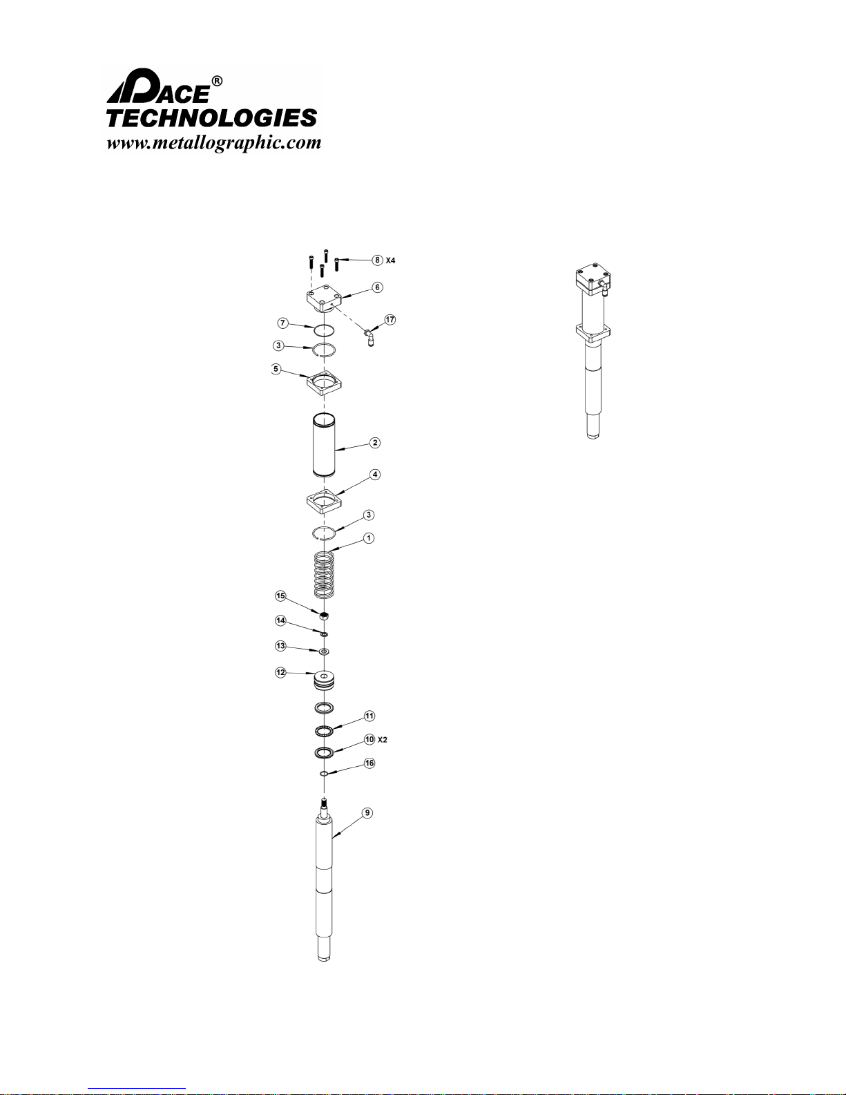
NANO 1000T / FEMTO 1500
Polishing Head
- - - - - - - - - - - - - - - - - - - - - - - - - - - - - - - - - - - - - - - - - - - - - - - - - - ▲ INSTRUCTION MANUAL
3601 E. 34th St. Tucson, AZ 85713 USA Tel. +1 520-882-6598 Fax +1 520-882-6599 email: pace@metallographic.com Web: http://www.metallographic.com
FEMTO 1500 Post Assembly - Exploded
Please read this instruction manual carefully and follow all installation, operating and safety guidelines.
85

Item Part Number Description Total QTY
1
FM-AC11 Spring of post-actuator
1
2
FM-AC04 Sl ee ve of pos t-a ctua tor
1
3
FM-AC09 Jump ring of post-actuator
1
4
FM-AC05 Flange of post-actuator
1
5
FM-AC03 Flange of post-actuator
1
6
FM-AC06 End cap of post-actuator
1
7
FM-AC08 O-ring of post-actuator
1
8
N/A Allen Bolt M6 1.0x30mm
4
9
FM-003 Shaft for post-actuator
1
10 1
11 1
12
FM-AC01 Piston block of post-actuator
1
13
N/A
M12 Washer 1
14
N/A
M12 Lock Washer 1
15
N/A
M12 Hex Nut 1
16
AM-AC10
Small O-ring of Post Actuator 1
17
T-M5-P4-L
Air connector 1
Surface Bearing
FM-AC08
NANO 1000T / FEMTO 1500
Polishing Head
- - - - - - - - - - - - - - - - - - - - - - - - - - - - - - - - - - - - - - - - - - - - - - - - - - ▲ INSTRUCTION MANUAL
3601 E. 34th St. Tucson, AZ 85713 USA Tel. +1 520-882-6598 Fax +1 520-882-6599 email: pace@metallographic.com Web: http://www.metallographic.com
FEMTO 1500 Post Assembly - Exploded (continued)
Please read this instruction manual carefully and follow all installation, operating and safety guidelines.
86
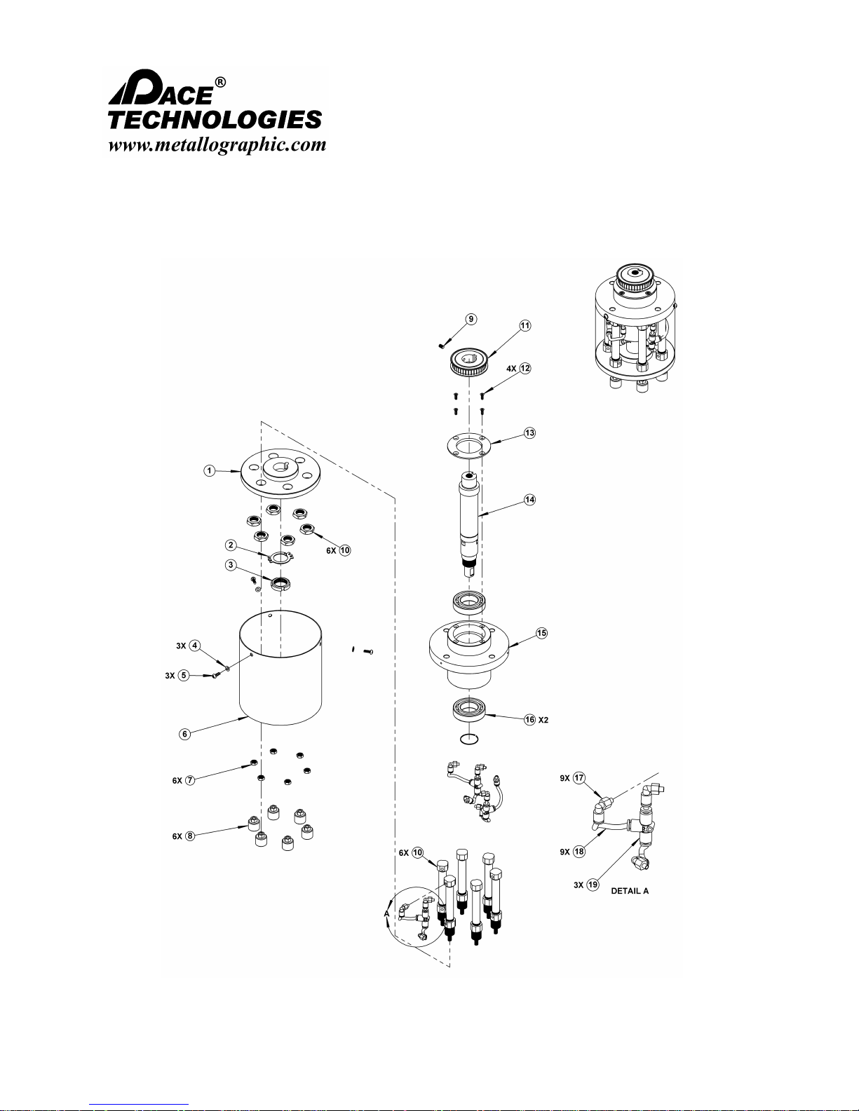
NANO 1000T / FEMTO 1500
Polishing Head
- - - - - - - - - - - - - - - - - - - - - - - - - - - - - - - - - - - - - - - - - - - - - - - - - - ▲ INSTRUCTION MANUAL
3601 E. 34th St. Tucson, AZ 85713 USA Tel. +1 520-882-6598 Fax +1 520-882-6599 email: pace@metallographic.com Web: http://www.metallographic.com
FEMTO 1500 Base Flange Assembly
Please read this instruction manual carefully and follow all installation, operating and safety guidelines.
87

Item Part Number Description Total QTY
1
FM-M-032
Small cylinder holder 1
2
N/A
Tighten gasket 1
3
N/A
M24x1.5 round nut 1
4
N/A
Flat Washer M4 3
5
N/A
Pan Head M4 0.7x12mm 3
6
FM-M-PRH
Piston rod housing 1
7
N/A
M6 Hex Nut 6
8
FM-AL-BOOT
Aluminum Piston Boot 6
9
N/A
M5 0.8x8mm Allen Set Screw 1
10 FM-003 FEMTO 1100 Piston cylinders (ea ch) 6
11
FM-M-030
Motor gear 1
12
N/A
Flat Head Screw M4 0.7x10mm 4
13
FM-M-HTCP
Housing top cover plate 1
14
FM-MG-002
Rotation shaft 1
15
FM-M-025
Base flange 1
16
N/A
FEMTO Shaft Bearing 2
17
T-M5-P4-L
Air connector 90deg 9
18
AH-6MM
Air Line Tube 9
19
T-P4-T
Air connector "T" 3
NANO 1000T / FEMTO 1500
Polishing Head
- - - - - - - - - - - - - - - - - - - - - - - - - - - - - - - - - - - - - - - - - - - - - - - - - - ▲ INSTRUCTION MANUAL
3601 E. 34th St. Tucson, AZ 85713 USA Tel. +1 520-882-6598 Fax +1 520-882-6599 email: pace@metallographic.com Web: http://www.metallographic.com
Please read this instruction manual carefully and follow all installation, operating and safety guidelines.
88

NANO 1000T / FEMTO 1500
Polishing Head
- - - - - - - - - - - - - - - - - - - - - - - - - - - - - - - - - - - - - - - - - - - - - - - - - - ▲ INSTRUCTION MANUAL
3601 E. 34th St. Tucson, AZ 85713 USA Tel. +1 520-882-6598 Fax +1 520-882-6599 email: pace@metallographic.com Web: http://www.metallographic.com
9.1 Schematics (FEMTO electrical)
Please read this instruction manual carefully and follow all installation, operating and safety guidelines.
89

NANO 1000T / FEMTO 1500
Polishing Head
- - - - - - - - - - - - - - - - - - - - - - - - - - - - - - - - - - - - - - - - - - - - - - - - - - ▲ INSTRUCTION MANUAL
3601 E. 34th St. Tucson, AZ 85713 USA Tel. +1 520-882-6598 Fax +1 520-882-6599 email: pace@metallographic.com Web: http://www.metallographic.com
9.2 Schematics
Please read this instruction manual carefully and follow all installation, operating and safety guidelines.
90

NANO 1000T / FEMTO 1500
Polishing Head
- - - - - - - - - - - - - - - - - - - - - - - - - - - - - - - - - - - - - - - - - - - - - - - - - - ▲ INSTRUCTION MANUAL
3601 E. 34th St. Tucson, AZ 85713 USA Tel. +1 520-882-6598 Fax +1 520-882-6599 email: pace@metallographic.com Web: http://www.metallographic.com
9.2 Schematics 9.2 Schematics (FRP Cover)
Please read this instruction manual carefully and follow all installation, operating and safety guidelines.
91
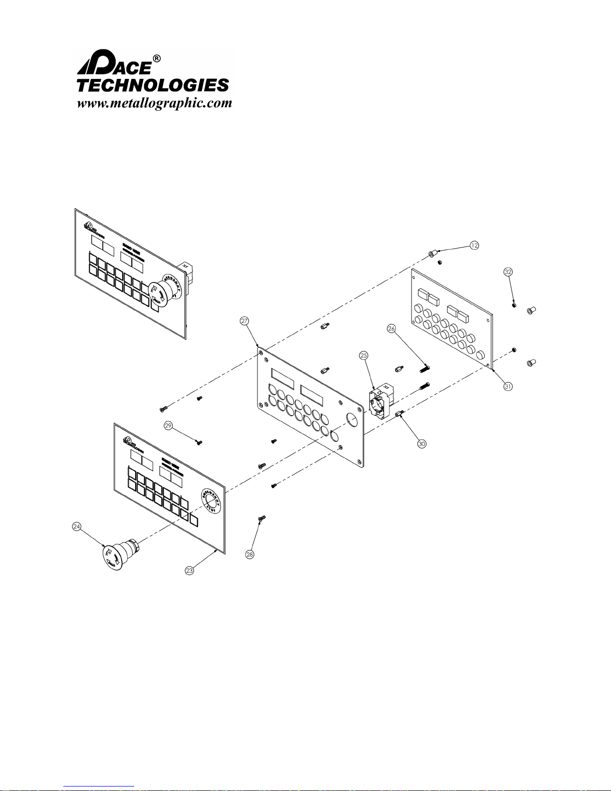
NANO 1000T / FEMTO 1500
Polishing Head
- - - - - - - - - - - - - - - - - - - - - - - - - - - - - - - - - - - - - - - - - - - - - - - - - - ▲ INSTRUCTION MANUAL
3601 E. 34th St. Tucson, AZ 85713 USA Tel. +1 520-882-6598 Fax +1 520-882-6599 email: pace@metallographic.com Web: http://www.metallographic.com
9.2 Schematics (Front Panel)
Please read this instruction manual carefully and follow all installation, operating and safety guidelines.
92
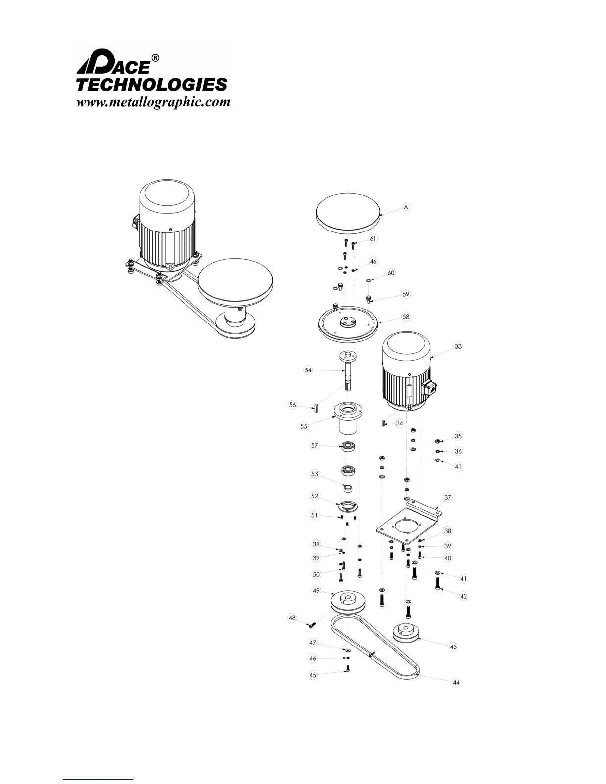
NANO 1000T / FEMTO 1500
Polishing Head
- - - - - - - - - - - - - - - - - - - - - - - - - - - - - - - - - - - - - - - - - - - - - - - - - - ▲ INSTRUCTION MANUAL
3601 E. 34th St. Tucson, AZ 85713 USA Tel. +1 520-882-6598 Fax +1 520-882-6599 email: pace@metallographic.com Web: http://www.metallographic.com
9.2 Schematics (Drive System)
Please read this instruction manual carefully and follow all installation, operating and safety guidelines.
93
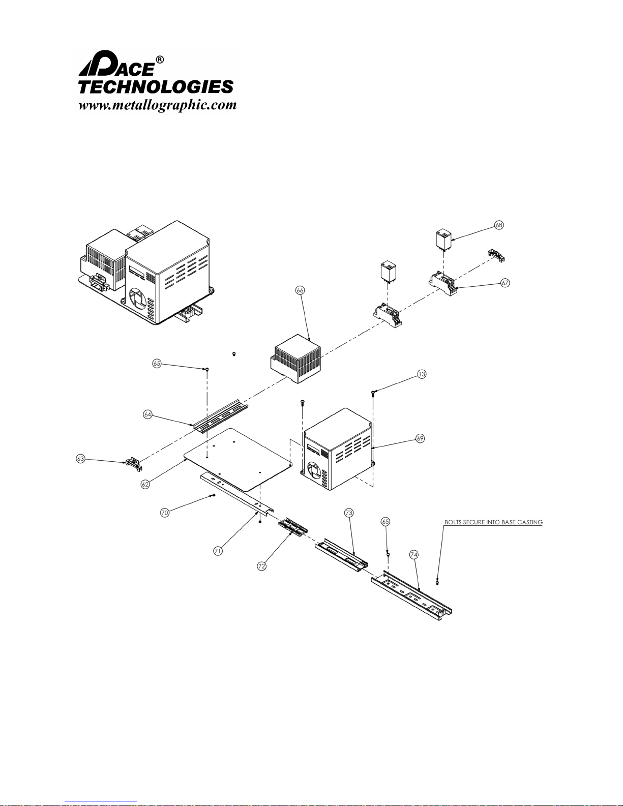
NANO 1000T / FEMTO 1500
Polishing Head
- - - - - - - - - - - - - - - - - - - - - - - - - - - - - - - - - - - - - - - - - - - - - - - - - - ▲ INSTRUCTION MANUAL
3601 E. 34th St. Tucson, AZ 85713 USA Tel. +1 520-882-6598 Fax +1 520-882-6599 email: pace@metallographic.com Web: http://www.metallographic.com
9.2 Schematics (Electronics System)
Please read this instruction manual carefully and follow all installation, operating and safety guidelines.
94
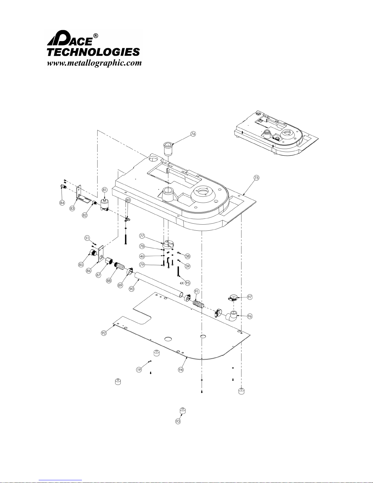
NANO 1000T / FEMTO 1500
Polishing Head
- - - - - - - - - - - - - - - - - - - - - - - - - - - - - - - - - - - - - - - - - - - - - - - - - - ▲ INSTRUCTION MANUAL
3601 E. 34th St. Tucson, AZ 85713 USA Tel. +1 520-882-6598 Fax +1 520-882-6599 email: pace@metallographic.com Web: http://www.metallographic.com
9.2 Schematics (Base and Plumbing)
Please read this instruction manual carefully and follow all installation, operating and safety guidelines.
95

NANO 1000T / FEMTO 1500
Polishing Head
- - - - - - - - - - - - - - - - - - - - - - - - - - - - - - - - - - - - - - - - - - - - - - - - - - ▲ INSTRUCTION MANUAL
3601 E. 34th St. Tucson, AZ 85713 USA Tel. +1 520-882-6598 Fax +1 520-882-6599 email: pace@metallographic.com Web: http://www.metallographic.com
9.3 Item Numbers List
ITEM PART NUMBER DESCRIPTION TOTAL QTY
1 N1-001 FRP COVER 1
2 W-E-8MM-FEMALE
3 F-ADAPTER FAUCET ADAPTER 1
4
5 FAUCET LOCK/RETAINER GASKET 1
6 FAUCET SUBASSEMBLY 1
7
8 BOWL SPRAYER HOSE LOCK 1
9 BOWL SPRAYER 1
10 BOWL SPRAYER BANJO BOLT 1
11 P-ADAPTER BOWL SPRAYER ADAPTER 1
12 N/A PANEL INSERT FOR M4x 0.7 6
13 N/A PAN HEAD PHILLIPS M4 0.7 x 12MM 8
14 PC-001 COMMUNICATION SOCKET 1
15 N/A COMM RETAINING NUT 17MM OD X 1MM 1
16 PC-002 FEMTO COMMUNICATION SOCKET 1
17 PS-001 POWER SWITCH AND SOCKET 1
18 N/A PAN HEAD PHILLIPS M4 0.7 x 8MM 4
19 N/A M4 FLAT WASHER 10
20 N1-014B REAR METAL COVER/PANEL 1
21 N/A M4 HEX NUT 4
22 N1-M-002 FEMTO CUTOUT COVER 1
23 N1-T DISPLAY TEMPLATE 1
24
25 EMERGENCY STOP SWITCH 1
26 N/A
27 N1-M-007 DISPLAY METAL PLATE 1
28 N/A FLAT HEAD PHILLIPS BOLT M4 0.7 x 10MM 4
29 N/A FLAT HEAD PHILLIPS BOLT M3 0.5 x 6.25MM 4
30 N/A BOLT ADAPTER/STANDOFF M3 x 0.5 4
31 N1-015B CONTROL CIRCUIT BOARD 1
32 N/A M3 HEX NUT 4
33 N1-007B ELECTRICAL DRIVE MOTOR (750W - 1HP) 1
34 N1-20MM-K SHAFT KEY 20MM x 5MM x 5.15MM 1
35 N/A M8 HEX NUT 4
36 N/A M8 LOCK WASHER 4
37 N1-M-008 MOTOR MOUNTING BRACKET 1
38 N/A M6 FLAT WASHER 11
PVL
P-RINSE
N1-013
90 DEG 8MM OD COMPRESSION FITTING (FEMALE
END)
FAUCET LOCK/RETAINER 1
BANJO BOLT REATINER 1
EMERGENCY STOP KNOB 1
EMERGENCY STOP ADJUSTMENT SCREWS M4 0.7
x 14MM
1
2
Please read this instruction manual carefully and follow all installation, operating and safety guidelines.
96
 Loading...