

Page 1
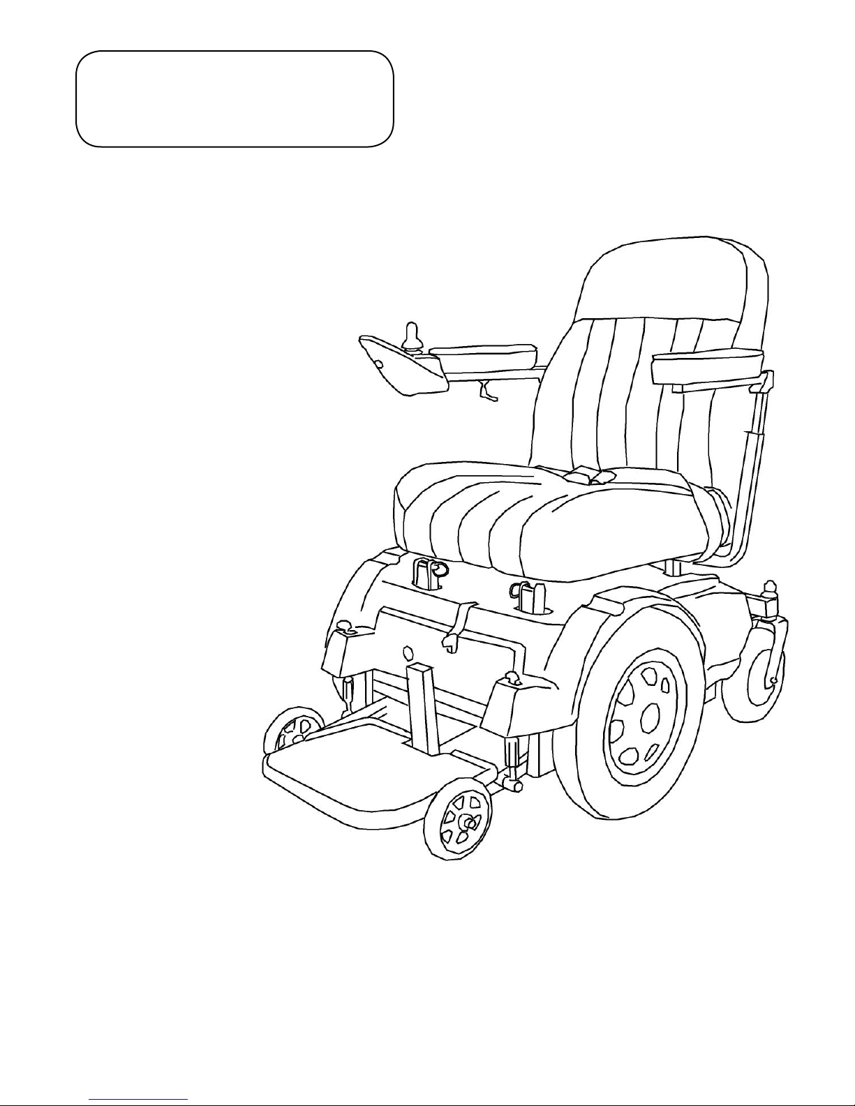
PaceSaver
®
TM
Scout RF [For Tilt]
Scout
Scout RF-P3 / RF-P4
Owner's Manual
(Must Be Given to User)
Boss 4.5
Set Your Own Pace!
READ this entire Owner's Manual BEFORE
you operate your new power wheelchair!
38 BOSS 4.5, RF, P3 & P4 OWNERS MANUAL
PN 82405
Revised 0412
B45P34OM0412.indd
Page 2

"SPECIAL OPTION" WARNINGS
WARNING: To make adjustments while sitting in the Scout, you must
be secured by wearing your lap belt to prevent you from falling forward.
TO ADJUST FRONT ANTI-TIP WHEEL HEIGHT
Turn thumbscrews clockwise to maximum height position.
Then lower wheel arm by turning thrmbscrews conterclockwise.
Count the number of turns as you lower each side to have equal
wheel height on both sides.
Remember, the lower the anti-tip wheel the better the front stability
when stopping as you go down an incline.
39 BOSS 4.5, RF, P3 & P4 OWNERS MANUAL
Page 3

Table of Contents
THIS MANUAL COVERS THE OPERATION OF YOUR NEW
PaceSaver POWER WHEELCHAIR. BE SURE AND FIND
THE INFORMATION THAT PERTAINS TO YOUR NEEDS BEFORE OPERATING.
Introduction 2
Important Safety Information 3
Specifi cations 11
Getting On and Off the Power Wheelchair
12
Operating the Power Wheelchair
13
Controller Instructions 16
Your First Ride 17
The Power Wheelchair
Braking Systems 18
Brake Disengage Mechanism 18
Seat Assembly Operation 20
Disassembly & Assembly 21
The Wheelchair Batteries 22
Charging Your Batteries 26
General Care, Diagnostic & Maintenance Section 30
Diagnostics & Faults 32
Commonly Asked Questions and Possible Answers 33
Warranty Information 37
PN 82405
Revised 0412
B45P34OM0412.indd
BOSS 4.5, RF, P3 & P4 OWNERS MANUAL 1
Page 4

Introduction
PaceSaver Scout Boss 4.5, RF-P3 & RF-P4 Owners Manual
Congratulations on your choice of a power wheelchair! It is a dependable vehicle built for
power and performance. Its easy to operate controls give you more of what you are looking for in a
wheelchair.
But it is important that you understand what your power wheelchair is, and what it is not. Our
power wheelchairs (like all power wheelchairs) are designed to provide safe, reliable transportation to
older or moderately physically disabled individuals who have diffi culty in getting around. It will safely
take you everywhere the specifi cations indicate as long as you follow the simple safety guidelines shown
on the next few pages.
The power wheelchair is not an all terrain vehicle that you can use out in the fi elds to drag brush
around or climb steep hills. It was not meant to go hunting in, or transport you thru hazardous envir onments. It also was not designed for the severely handicapped individual who should not be in a power
wheelchair. You must have good stability, motor control and above all else, good common sense to use
our wheelchair, or any other brand. If you feel that you cannot safely operate this vehicle at all times,
you should not use this power wheelchair!
Important
Please read the entire manual carefully before attempting to drive your new power wheelchair.
Remember to read all service recommendations outlined in this manual to achieve trouble free,
safe and enjoyable operation of your power wheelchair. Failure to follow the recommended service procedures will damage your power wheelchair and such damage is not covered under warranty. Contact
your dealer if you have questions after reading this manual.
Leisure-Lift specifi cally disclaims responsibility for any bodily injuries or property damage which
may occur during or because of improper use or any use which does not comply with applicable
Federal, State, or Local laws and ordinances or methods recommended in this manual. If in doubt
about your ability to operate your power wheelchair, consult your doctor.
2 BOSS 4.5, RF, P3 & P4 OWNERS MANUAL
Page 5

Safety Guidelines
NOTE: MODIFYING AND/OR TAMPERING IN ANY UNAUTHORIZED MANNER WITH THE
POWER WHEELCHAIR WILL VOID THE WARRANTY AND MAY CAUSE THE WHEELCHAIR TO
MALFUNCTION, EXPOSING YOU TO PHYSICAL HARM.
ATTENTION: This manual contains specifi c information about your power wheelchair. While some of
the information is the same for all power wheelchairs, make sure that you follow the specifi cations and
directions that apply to your powerchair. If you are unsure of the style powerchair you have, contact
your dealer.
Your powerchair is a vehicle which provides independence and freedom to people with limited mobility.
Driver error can cause injury to the driver and to other people. Please use common sense, courtesy , and
obey the following guidelines for vehicle operation.
READ THIS ENTIRE MANUAL BEFORE DRIVING THIS VEHICLE.
Safety Guidelines
Always turn the power switch to the OFF position when stopped or when getting off or on the power wheel-
chair. This keeps you from accidentally hitting the throttle and causing an accident. For persons with
limited lower body strength, or persons who make slide transfers and may forget to turn the power
switch off, we recommend special caution.
DO NOT operate the unit if it behaves erratically, or shows abnormal response, heating, smoking or arcing.
Turn the system off at once and call your dealer for service.
Use extra caution
due to risk of tipping and injury.
Do not exceed the incline specifi cations for your power wheelchair or it will become unstable and tipping will
result. Persons with limited ability to protect themselves (like persons paralyzed on one side) should
use protective equipment such as bicycle headgear. The specifi cation chart in your manual will indicate
the maximum incline for your particular style power wheelchair.
Keep your feet on the footrests while riding the power wheelchair to avoid hitting them on objects as you
drive. Always wear shoes while operating your power wheelchair.
Always wear your lap belt when riding your power wheelchair.
Secure the removable seat assembly before operating the power wheelchair to prevent yourself from falling
from the seat while moving.
Remember, The power wheelchair is built to carry a single person. Do not carry passengers under any cir-
cumstances or accidents and bodily injury might occur.
Ensure driving surface, ramp, platform lift or elevator is capable of supporting combined weight of user and
wheelchair.
Always
go straight up or down curb cuts. You want the front wheels and the rear wheels to climb up or go down
together, not one at a time. Not doing this will result in the
side to side (as a car would in a ditch) or the
ramps the same way , straight on, not at an angle. NEVER attempt to go up or down a regular height curb
or tipping and personal injury will result!
when riding your
power wheelchair
Refer to the maximum incline rating on the specifi cation chart.
off of the pavement or on rough, soft or uneven surfaces
power wheelchair
power wheelchair
BOSS 4.5, RF, P3 & P4 OWNERS MANUAL 3
overturning. Also approach curb access
violently swinging from
Page 6

Safety Guidelines
Warning Driving the power wheelchair in busy streets, busy parking lots, or in crowded shopping malls can
be dangerous for you or other people as you may be struck by a vehicle or you might strike a pedestrian.
Use caution in congested areas at all times.
Lean forward a slight amount when traveling up an incline.
NEVER
Use caution when driving off even a small curb or raised surface. The act of dropping off the edge subjects
Disconnect the batteries before performing any maintenance. This avoids the possibility of injuries due to
Follow the directions of your doctor and/or pharmacist at all times. Do not drive the power wheelchair while
taking medications that affect your refl exes or judgment, as your driving will be impaired and accidents may
result. Do not drink alcohol or use any other stimulants while operating this or any other vehicle.
The following are important things to help you drive the power wheelchair in the safest possible
manner. Please take note of each and every one.
WARNING: DO NOT engage in the following activities with your power wheelchair or serious personal
injury may result.
leave your
power wheelchair
other inclement weather (dust or sand storms, etc.). Use only a damp rag to clean your
(never use solvents or abrasive cleaners). The use of excessive water, as from a garden hose or bucket
may cause damage to your
the power wheelchair to extreme forces that can damage the frame and other components. This type
of damage is not covered under warranty.
shock. Make sure that the batteries are reconnected and secured before using the power wheelchair.
power wheelchair
on an outside car-lift during periods of high moisture ( mist, rain, snow, etc.) or any
exposed to the elements. This includes storage outside or carrying the
power wheelchair
power wheelchairs
electronics.
DO NOT ride the power wheelchair with the brake disengaged at anytime.
DO NOT drive the power wheelchair diagonally across inclines, turn sharp on an incline or make turns at or
near full throttle at any time. Doing this will result in the power wheelchair losing traction and control which
can result in tipping and possibly serious injuries.
DO NOT drive the power wheelchair with the seat assembly higher than necessary as tipping and serious
injury may result. The lower the seat, the better your stability.
DO NOT drive the power wheelchair with under-infl ated tires as this increases the possibility of tipping and
injury. Your stability and effi ciency (power and range) are also greatly affected.
DO NOT remain seated on your power wheelchair while it is being loaded into a vehicle using anything other
than a special wheelchair lift, or personal injury may result.
DO NOT
may result in serious injury.
DO NOT
to stop in level, fl at areas where there is no possibility of rolling, or tipping the unit or having the occupant fall
out.
ride on soft, uneven surfaces as this can cause lose of traction and control causing tipping and that
stop on any incline to rest or dismount. Although the electric brake will stop and hold you, it is best
4 BOSS 4.5, RF, P3 & P4 OWNERS MANUAL
Page 7

Safety Guidelines
DO NOT ride your power wheelchair without wearing your lap belt at all times or serious injury may result.
This is especially important on ramps or inclines.
Leisure-Lift
WARNING: Do not engage in the following activities with your power wheelchair or serious injury
may result.
Do not remain seated on your power wheelchair while it is being loaded into a vehicle using anything
other than a special wheelchair lift.
Riding on a platform lift is dangerous. Failure to check weight capacity, turn off controller, have the
required precise driving control capability or have the wheelchair properly maintained could result in
serious injury or death.
Do not use the power wheelchair as a seat in a moving vehicle. As of this date, the Department of
Transportation has not approved any tie down system for transportation of a user while in a power
wheelchair in a moving vehicle of any type. The rider must be seated in a regular automotive seat and
restrained by an approved automobile safety belt. The rider must be warned that there is a many times
greater likelihood of sever injury or death in the event of an accident if they are not in the provided
automotive seat and restraint system. The following attachment points are provided for the sole purpose
of securing the mobility device without the rider. The power wheelchair and batteries MUST be independently and properly restrained or stored in a separate compartment so as to prevent it from causing
injury in an accident.
®
POWER WHEELCHAIR TIE DOWN INFORMATION
CONVENIENT TIE DOWN POINTS
The following is a list of convenient locations that the straps from a 4 point securement system could
be anchored on PaceSaver products. These products have not been crash tested and certifi ed as crash
worthy using these locations.
POWER WHEELCHAIRS
SCOUT, SCOUT RF, SCOUT RF 4, BOSS, BOSS 4.5, BOSS 6NS, SCOUT RF-P3, P4 AND SCOUT EXPLORER
Back anchor points - Place a strap around the lower portion of each armrest support.
Front anchor points - Place a strap around each anti-tip wheel support arm just above the small anti-tip
wheel.
DO NOT drive up, down or across inclines greater than the rating for your style power wheelchair or tipping
will result. Refer to the Specifi cation Sheet (Please Note: Soft surfaces reduce the incline capability
by more than 50%). Wet or slick surfaces reduce steering and braking controls tremendously. Use
extreme caution in these circumstances.
DO NOT travel down ramps at high speed. Doing so will reduce traction and increase stopping distance.
BOSS 4.5, RF, P3 & P4 OWNERS MANUAL 5
Page 8

Safety Guidelines
DO NOT allow the power wheelchair controls to become wet. Never wash off the power wheelchair using a
hose or a stream of water, drive through standing water or ride in the rain. Possible loss of control and/or
electronic damage will occur. Do not attempt to ride a power wheelchair that has been soaked until it has
had a chance to dry thoroughly .
DO NOT leave the power wheelchair where it is exposed to high temperatures (a car trunk, etc.) or to poo
weather conditions such as rain or snow or freezing conditions as damage to the unit will occur.
DO NOT disassemble any wheel at any time while still infl ated. The pressure may blow wheel rims apart
while you are loosening them.
DO NOT ride the unit near platforms, stairs, ledges, curbs or in any other potentially dangerous situation as
serious injury can result.
DO NOT ride the power wheelchair over power cords, oxygen lines, hoses or any other material that
could become entangled in the wheels or get caught in the drive mechanism of the power wheelchair
or while connected to equipment off of the power wheelchair.
DO NOT attempt to reach objects if you have to move forward in the seat.
DO NOT attempt to reach objects if you have to pick them up from the fl oor by reaching down between
your knees.
DO NOT lean over the top of the seat back to reach objects from behind as this may cause the power
wheelchair to tip over or cause you to fall out.
DO NOT shift your weight or sitting position toward the direction you are reaching as the power wheelchair
may tip over.
DO NOT tilt the power wheelchair without assistance.
DO NOT use an escalator to move a power wheelchair between fl oors. Serious bodily injury may occur .
ALWAYS turn the power wheelchair power OFF and engage the motor locks/clutches to prevent the wheels
from moving BEFORE attempting to transfer in or out of the power wheelchair. Also make sure every precaution is taken to reduce the gap distance.
DO NOT engage or disengage the motor locks/clutches until the power is in the OFF position.
DO NOT operate on roads, streets or highways.
DO NOT climb, go up or down hard surface ramps greater than allowed in specifi cations. Use special cau-
tion on soft surfaces as they greatly reduce incline rating. See specifi cations for your power wheelchair .
DO NOT attempt to move up or down an incline with a water, ice or oil fi lm or loss of control & braking
will result.
DO NOT attempt to drive over curbs or obstacles greater than maximum climbing capability shown in
specifi cations. Doing so may cause your power wheelchair to turn over and cause bodily harm or damage to
the power wheelchair.
6 BOSS 4.5, RF, P3 & P4 OWNERS MANUAL
Page 9

Safety Guidelines
DO NOT use unauthorized parts, accessories, or adapters other than those authorized by Leisure-Lift.
DO NOT attempt to lift the power wheelchair by lifting on any removable (detachable) parts. Lifting by
means of any removable (detachable) parts of a power wheelchair may result in injury to the user of damage to the power wheelchair.
DO NOT stand on the frame of the power wheelchair.
DO NOT use the footplate as a platform. When getting in or out of the power wheelchair, make sure that
the footplate are in the upward position or swing footrests towards the outside of the power wheelchair.
See - Getting On and Off the Power Wheelchair.
We realize that many bariatric persons cannot do a side transfer or raise their legs to raise and lower the
footplate. If and only if you must step on the footplate for entering or exiting the power wheelchair, you
must follow these instructions. Your power wheelchair is equipped with a patented infi nitely adjustable rigid
anti-tip system (see fi gure 1 under Battery Removal Section). When both of the front anti-tip wheels are
lowered to contact the fl oor, you can step on the platform without tipping the chair forward. After entry the
wheels must be raised to adjust to the driving environment - 1/4” for fl at fl oors and up to 2” for outdoor
terrain. Always keep the adjustment as low as possible for your driving area. Warning: Failure to lower the
anti-tip wheels for entry and exit will result in the chair tipping forward when you stand on the footplate
which can cause you to fall and result in possible serious injury. Warning: As with any power wheelchair
part should the anti-tip assembly become damaged, discontinue use immediately and contact your dealer for
service. Warning: Always keep anti-tip wheels at the same height from fl oor to prevent tipping to side.
ALWAYS wear your lap belt.
ELECTRICAL
EXTREME care should be exercised when using oxygen in close proximity to electric circuits. Contact
your oxygen supplier for instruction in the use of oxygen.
Grounding instructions:
DO NOT, under any circumstances, cut or remove the round grounding prong from any plug used with or
for Leisure-Lift products. Some devices are equipped with three-prong (grounding) plus for protection
against possible shock hazards. Where a two-prong wall receptacle is encountered, it is the personal responsibility and obligation of the customer to contact a qualifi ed electrician and have the two-prong receptacle
replaced with a properly grounded three-prong wall receptacle in accordance with the National Electrical Code. If you must use an extension cord, use ONLY a three-wire extension cord having the same or
higher electrical rating as the device being connected. In addition, Leisure-Lift has placed RED/ORANGE
WARNING TAGS on some equipment. DO NOT remove these tags. Carefully read battery/battery charger
information prior to installing, servicing or operating your wheelchair.
RAIN & MOISTURE
LEISURE-LIFT has established the following rules for dealing with moisture.
BOSS 4.5, RF, P3 & P4 OWNERS MANUAL 7
Page 10

Safety Guidelines
End user or their attendant should allow suffi cient time to remove his/her power wheelchair prior to a rain
storm or inclement weather to retain wheelchair operation.
DO NOT leave your power wheelchair in a rain storm of any kind.
DO NOT use your power wheelchair in a shower or leave it in a damp bathroom while taking a shower.
DO NOT leave your power wheelchair in a damp area for any length of time. Direct exposure to rain or
dampness will cause the wheelchair to malfunction electrically and mechanically; may cause the wheelchair
to prematurely rust.
Check to ensure that the batteries are secured in place, the joystick boot is NOT torn or cracked where water
can enter and that all electrical connections are secure at all times.
DO NOT use the joystick if the boot is torn or cracked. If the joystick boot becomes torn or cracked, replace IMMEDIATELY.
WEIGHT TRAINING
Leisure-Lift DOES NOT recommend the use of its power wheelchair as a weight training apparatus. Power
wheelchairs have NOT been designed or tested as a seat for any kind of weight training. If occupant uses
said wheelchair as a weight training apparatus, Leisure-Lift shall NOT be liable for bodily injury and the
warranty will be voided immediately.
SAFETY/HANDLING OF POWER WHEELCHAIRS
“Safety and Handling” of the wheelchair requires the close attention of the wheelchair user as well as the as-
sistant. This manual points out the most common procedures and techniques involved in the safe operation
and maintenance of the wheelchair. It is important to practice and master these safe techniques until you are
comfortable in maneuvering around the frequently encountered architectural barriers.
Use this information only as a “basic” guide. The techniques that are discussed on the following pages have
been used successfully my many.
Individual wheelchair users often develop skills to deal with daily living activities that may differ from those
described in this manual. Leisure-Lift recognized and encourages each individual to try what works best
for him/her in overcoming architectural obstacles that they may encounter. Techniques in this manual are a
starting point for new wheelchair users and assistants with “safety” as the most important consideration for
all.
ST ABILITY AND BALANCE
WARNING
Always wear your lap belt.
To assure stability and proper operation of your wheelchair, you must at all times maintain proper balance.
Your wheelchair has been designed to remain upright and stable during normal daily activities as long as
you do not move beyond the center of gravity. The anti-tip wheels are normally positioned approximately
two inches off the ground (with a rider in the chair) but may be adjusted in height downward by your dealer.
Because your power wheelchair is a "midi" (3/4) drive chair the anti-tip wheels are normally only used
when braking going forward down a steep incline. Reducing this setting causes the powerchair to tilt forward at a lesser angle before resting on the anti-tip wheels if you decelerate rapidly while going down a hill.
8 BOSS 4.5, RF, P3 & P4 OWNERS MANUAL
Page 11

Safety Guidelines
The normal adjustment should allow the power wheelchair to climb a two inch obstacle.
DO NOT lean forward out of the wheelchair any further than the length of the armrests.
STAIRWAYS - WARNING
DO NOT attempt to move an occupied power wheelchair between fl oors using a stairway or escalator. Use
an elevator to move an occupied power wheelchair between fl oors. If moving a power wheelchair between
fl oors by means of a stairway, the occupant MUST be removed and transported independently of the power
wheelchair Again, DO NOT use an escalator to move a wheelchair between fl oors. Serious bodily injury
may occur..
Extreme caution is advised when it is necessary to move an UNOCCUPIED power wheelchair up or down
the stairs. Leisure-Lift recommends disassembling your wheelchair into smaller, more manageable components to keep from personal injury. Lifting by means of any removable (detachable) parts of a wheelchair
may result in injury to the user or damage to the wheelchair.
Follow this procedure for moving wheelchair between fl oors when an elevator is NOT available:
ESCALATORS - WARNING
DO NOT use an escalator to move a wheelchair between fl oors. Serious bodily injury may occur.
TRANSFERRING TO/FROM OTHER SEATS
WARNING
ALWAYS turn the wheelchair power OFF and engage the motor locks/clutches to prevent the wheels from
moving BEFORE attempting to transfer in or out of the wheelchair. Also make sure every precaution is taken
to reduce the gap distance. Always have an attendant or healthcare professional present while learning to properly transfer yourself.
CAUTION
When transferring, position yourself as far back as possible in the seat. This will prevent damaging the
upholstery and the possibility of the wheelchair tipping forward. See section Getting On and Off the Power
Wheelchair.
PERCENTAGE OF WEIGHT DISTRIBUTION
WARNING
DO NOT attempt to reach objects if you have to move forward in the seat or pick them up from the fl oor by
reaching down between your knees.
Many activities require the wheelchair user to reach, bend and transfer in and out of the wheelchair. These
movements will cause a change to normal balance, center of gravity, and weight distribution of the wheelchair. To determine and establish your particular safety limits, practice bending, reaching and transferring
activities in several combinations in the presence of a qualifi ed health professional BEFORE attempting
active use of the wheelchair. Remember. . . Keep your lap belt on at all times.
Never roll backward down an incline as caster rotation reduces rearward stability.
REACHING, LEANING, BENDING AND BENDING - FORWARD
BOSS 4.5, RF, P3 & P4 OWNERS MANUAL 9
Page 12

Safety Guidelines
Position the rear casters so that they are extended as far rearward as possible and engage motor locks/clutches. DO NOT LEAN FORWARD OF THE ARMRESTS.
REACHING, BENDING - BACKWARDS
WARNING DO NOT lean over the top of the back upholstery. This will change your center of gravity and
may cause you to tip over. Position wheelchair as close as possible to the desired object. Point rear casters
rearward to create the longest possible wheelbase. Reach back only as far as your arm will extend without
changing your sitting position.
WARNING: For units with the optional Power Seat, only drive the wheelchair when the power
seat is in the lowest position to avoid tipping and serious injury . If you are unable to follow this
instruction, consult your dealer for alternatives.
Persons having disabilities which limit their ability to remain erect without assistance, (stroke patients,
severe muscular diseases, etc.) should carefully evaluate whether they should operate a wheelchair at all. If
they decide, with the advise of their physician or another advisor, that they are capable of safely operating
a wheelchair, they should consider the use of a bicycle helmet or pads when operating a wheelchair. These
articles would help protect them should they fi nd themselves in a hazardous situation where they could tip
over or fall because of their lack of balance.
DIFFERENT STYLES OF POWER WHEELCHAIRS HAVE DIFFERENT INCLINE
CLIMBING ABILITIES. CAREFULLY STUDY THE CHART TO SEE THE CORRECT
SPECIFICATIONS FOR YOUR UNIT. DO NOT EXCEED THE SPECIFICATIONS OF
THE POWER WHEELCHAIR STYLE YOU PURCHASED!
10 BOSS 4.5, RF, P3 & P4 OWNERS MANUAL
Page 13

Specifi cations
Scout Boss 4.5
Seat Width Range: (optional up to 30")
Seat Depth:
Seat-to-Floor: (compressed foam) (18" Admiral)
Seat-to-Footrest: (compressed foam) (18" Admiral)
Overall Width: (No joystick, outside tire to outside tire)
Overall Height: (seat folded down)
Overall Length
Weight
Motor/Suspensions Section
Footplate/Front Anti-Tip System
Seat and Controller (18" Admiral)
TOTAL
Batteries (2)
Complete W/Batteries (AGM):
Battery/Size (Not Supplied)
Speed: Adjustable
Range*: (varies with weight and driving conditions)
Turning Radius:
Ground Clearance
Max Curb Climbing
Max. Incline Stability
Hard Surface
With Stanza
Tire Pressure
Front Anti-Tip Wheels
Main Drive Wheels - (optional Flat-Free)
Caster Wheels
Max. Weight Capacity
TM
18" - 24"
18" - 21"
19.75" - 22.75"
11.50" - 18.50"
25.5"
36" - 39"
44"
103.5 lbs.
14 lbs.
47 lbs.
164.5 lbs.
58.5 lbs. ea. (group 24)
281.5 lbs.
Group 22/24
5 mph Max.
19.5 - 25 miles
24.4"
3"
2.5"
o
- 450 lb. rider
9
o
- 300 lb. rider
12
Solid
Pneumatic - 50 psi
Solid
450 lbs.
NOTE: Special seats such as tilts reduce the max capacity by 50 lbs.
Scout RF
18" - 24"
18" - 21"
19.50" - 22.50"
15.50" - 19.50"
25"
36" - 39"
40.5"
111 lbs.
14 lbs.
45 lbs.
170 lbs.
39 lbs. ea. (group 22)
248 lbs.
Group 22
5 mph Max.
19.5 - 25 miles
21.5"
3"
2.5"
o
- 300 lb. rider
9
o
- 300 lb. rider
12
Solid
Pneumatic - 50 psi
Solid
450 lbs.
(non Power seat)
400lbs. - 425 lbs. with
tilt or power seat.
Scout RF-P3 & P4
18" - 24"
18" - 21"
19.50" - 22.50"
15.50" - 19.50"
25"
36" - 39"
40.5"
111 lbs.
14 lbs.
45 lbs.
170 lbs.
39 lbs. ea. (group 22)
248 lbs.
Group 22
5 mph Max.
19.5 - 25 miles
21.5"
3"
2.5"
o
9
- 450 lb. rider
o
- 300 lb. rider
12
Solid
Pneumatic - 50 psi
Solid
300 lbs. / 450 lbs.
Do Not Exceed The Maximum Incline Stability For Your Style Power Wheelchair!
Incline stability (maximum up-hill angle) is determined using applicable RESNA & ISO criteria for determining static and dynamic stability (ISO 7176-1 & 2, ANSI WC/01 & 02). T ests are conducted using the maximum
rider weight specifi ed in the owners manual and the seat in its' least favorable position.
*Range based on maximum size rider on a hard level surface with the maximum size batteries. Customer's
range may vary according to customer's weight and driving conditions.
9 degrees = 16%
12 degrees = 22%
BOSS 4.5, RF, P3 & P4 OWNERS MANUAL 11
Page 14

Getting On and Off the Power Wheelchair
The following is a recommended method for getting on your Power Wheelchair
1. The wheelchair should be stopped on a fl at level surface with the power switch in the OFF posi-
tion (no visible lights).
(SEE WARNING BELOW)
2. Raise the foot rest plate so that you may back up to the wheelchair squarely. WARNING: Do not use
the footplate as a platform. When getting in or out of the wheelchair make sure that the footplates are in the
upward position or swing footrest towards the outside of the wheelchair.
We realize that many bariatric persons can not do a side transfer or raise their legs to raise and lower the
footplate. If and only if you must step on the footplate for entering or exiting the power wheelchair, you
must follow these instructions. Your power wheelchair is equipped with a patented infi nitely adjustable rigid
anti-tip system (see fi gure 1 under Battery Removal Section). When both of the front anti-tip wheels are
lowered to contact the fl oor, you can step on the platform without tipping the chair forward. After entry the
wheels must be raised to adjust to the driving environment - 1/4” for fl at fl oors and up to 2” for outdoor
terrain. Always keep the adjustment as low as possible for your driving area. Warning: Failure to lower the
anti-tip wheels for entry and exit will result in the chair tipping forward when you stand on the footplate
which can cause you to fall and result in possible serious injury. Warning: As with any wheelchair part
should the anti-tip assembly become damaged, discontinue use immediately and contact your dealer for service. Warning: Always keep anti-tip wheels at the same height from fl oor to prevent tipping to side.
3. Position yourself squarely in front of the seat and lower yourself into the seat using the armrests if necessary. (Never use the control housing or joystick as a support while getting on and off the wheelchair.)
4. Lower the footrest and place your feet securely on the footrest.
5. Buckle the safety belt around yourself belt to help hold yourself securely in the chair.
6. Push the power button on the speed control, the LED lights should activate.
7. When seated comfortably, you can drive the power wheelchair.
WARNING: For units with the optional Power Seat, only drive the wheelchair when the power
seat is in the lowest position to avoid tipping and serious injury . If you are unable to follow this
instruction, consult your dealer for alternatives.
The method for getting off is the reverse procedure.
1. Turn the power switch OFF when stopped (no visible lights).
2. Unfasten your safety belt and raise (or have someone raise) the footrest bracket.
3. Make sure your feet are planted fi rmly on the ground and stand up.
WARNING
Keep the power button in the OFF position at all times when stopped or when getting on or off the wheelchair. Sudden accidental movement of the wheelchair will be avoided with the power switch in the OFF
position.
Tipping can occur if you get on the power wheelchair in a manner other than recommended. Tipping can be
avoided by keeping your weight away from the outer edges until seated. If you step into the wheelchair,
sit directly in the center of the seat, not near the edge. Tipping, loss of control or traction (wheel spin) can also
occur if you turn the joystick sharply while traveling at or near full throttle and on slick surfaces or inclines.
12 BOSS 4.5, RF, P3 & P4 OWNERS MANUAL
Page 15
Operating the Power Wheelchair
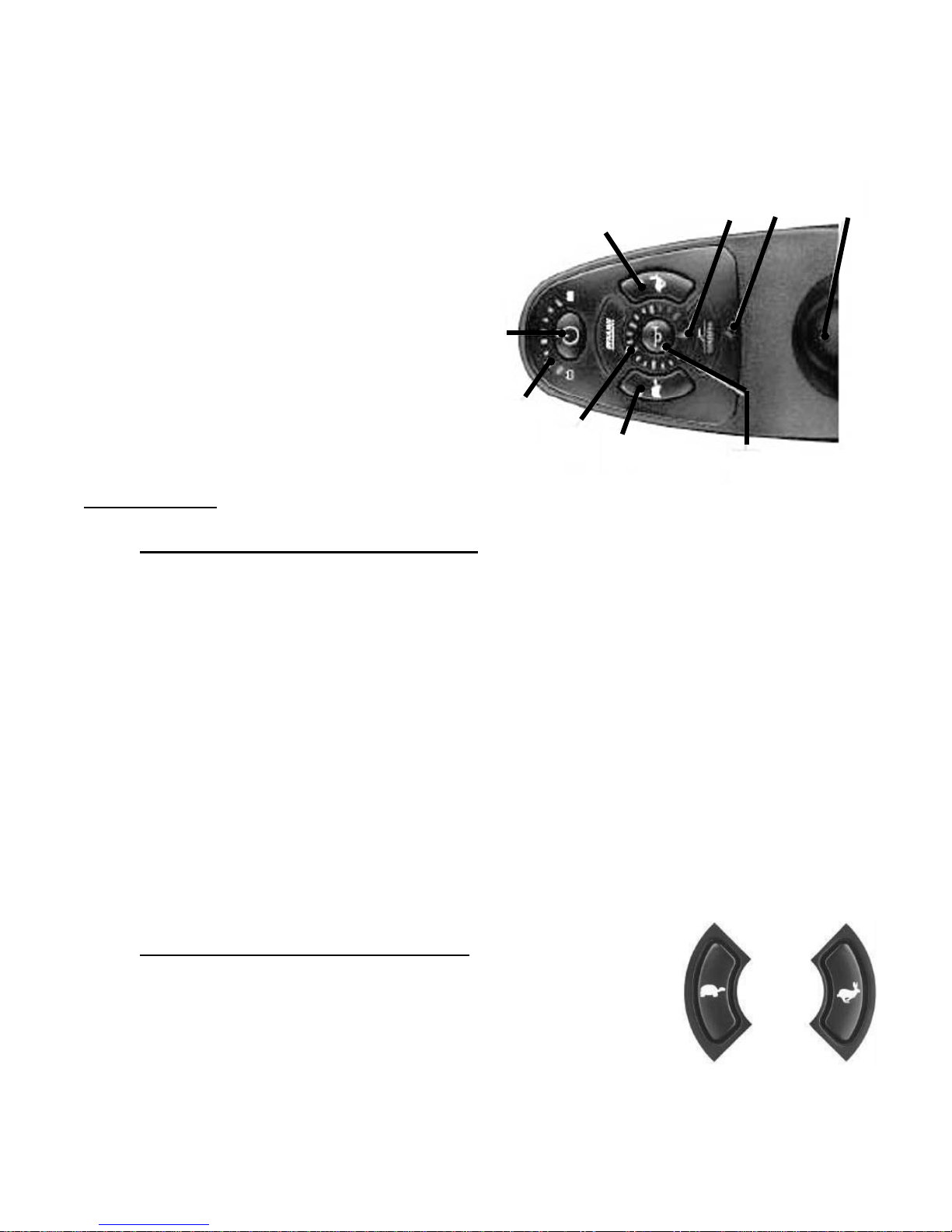
Controls for the power wheelchair operation are located on the arm mounted joystick console and the power
module mounted to the frame. Become familiar with all controls with the power button in the OFF position.
Each is described in the following section
1. On/Off
2. Increase/Decrease Speed
3. Battery Gauge
4. Joystick
5. Horn
6. Speedometer
7. Attendant Control LED
8. Service Indicator LED
Joystick Console
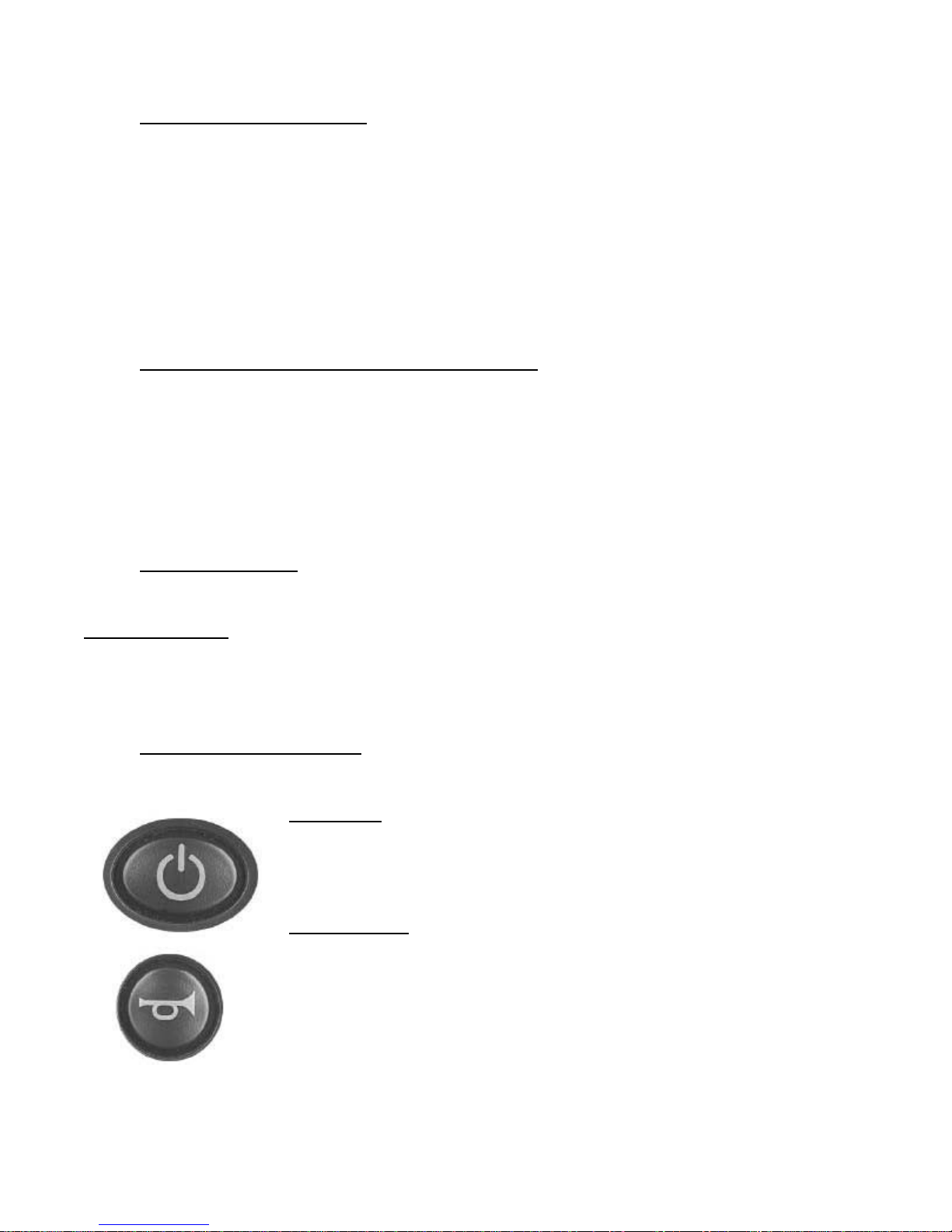
1. TURNING THE POWER ON and OFF Press the Power button once to turn the power on. All
indicators will fl ash briefl y. The current state of battery charge will be displayed and the powerchair may be
operated as normal.
Note: If the SHARK is turned on while the joystick is out of neutral, an OONAPU fault will be displayed - r efer
to the SHARK Display Information Chart.. Release the joystick back to neutral and the fault will disappear.
OONAPU (Out Of Neutral At Power Up) is a feature that prevents SHARK for driving if the joystick is out of
neutral when SHARK is turned on or an inhibit condition removed.
This feature prevents sudden and unexpected powerchair movements.
Press the Power button again to turn the power off. The LED's will turn off.
Note: Alternatively, SHARK may be placed into a Lock Mode (See Locking Instructions). This may be preferable to turning the power off if leaving the powerchair at a place where unauthorized persons may attempt to
use the powerchair.
2. ADJUSTING THE DRIVING SPEED The user can adjust the
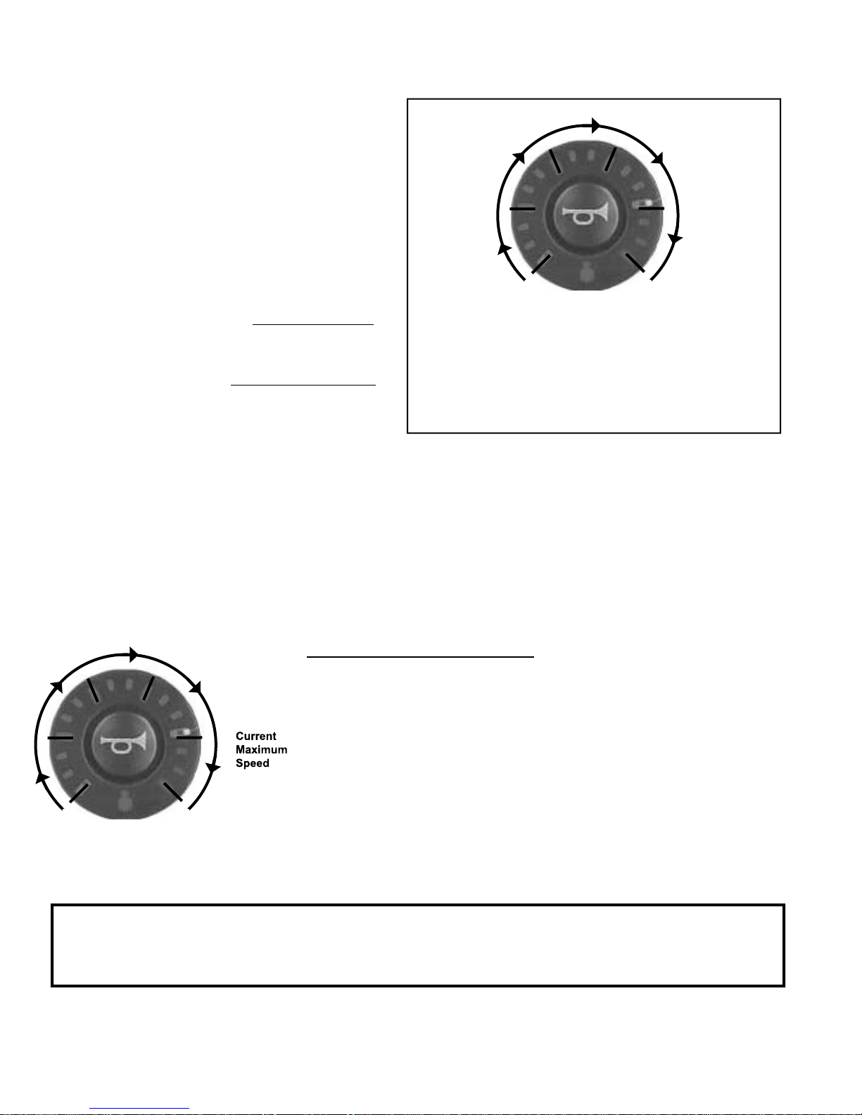
chair's top speed to suit their preferences and environment. The currently selected top speed is shown on the Speedometer and can be adjusted using the
"Increase Speed" (Hare) and "Decrease Speed" (Tortoise) buttons.
BOSS 4.5, RF, P3 & P4 OWNERS MANUAL 13
Page 16
Operating the Power Wheelchair
Each of the speedometer's 6 large LEDs
typically represent 0%, 20%, 40%, 60%, 80%
40%
Top Speed 2
60%
Top Speed 3
and 100% of the chair's absolute maximum top
speed.
REMD supports 2 modes of top speed
adjustment - "5 Speed" and "VSP" modes.
20%
Top Speed 1
80%
Top Speed 4
In the "5 Speed" mode pressing the
Increase Speed and Decrease Speed buttons
steps between the 5 top speeds 20% to
100%.
In the "VSP" mode a quick single press
of the Increase Speed and Decrease Speed
buttons also steps between one of the 5 speeds
20% to 100%. However, pressing and holding
the Increase Speed (Decrease Speed) Button
ramps the top Speed up (down) in fi ne steps,
0%
Top Speed 1
Typically 20% but programmable using the
Lowest Forward Speed parameter.
Top Speed 5
Typically 100% but programmable using the
Maximum Forward Speed parameter.
100%
Top Speed 5
allowing practically any top speed to be selected.
This can be particularly useful for matching the chair speed to the walking speed of an accompanying pedestrian.
VSP is an extremely powerful feature, allowing both fast stepping between fi xed top speeds by using
quick presses or fi ner control using long presses. The VSP feature can be enabled or disabled. Users can toggle
between the "VSP" and "5 Speed" Modes by holding down both the Increase Speed and Decrease Speed Buttons for approximately 2 seconds while the unit is powered up. The control unit will beep when the mode has
been changed.
USING THE SPEEDOMETER
The Speedometer is used to indicate the speed of the chair in
relation to the maximum speed possible. The right-most LED displays the
current maximum speed setting, which can be adjusted using the Increase
or Decrease Speed button. Refer to "Adjusting the Driving Speed" for
details. While using the joystick to increase the speed of the chair , the
LED's will fi ll in until the maximum speed is reached.
WARNING: For units with the optional Power Seat, only drive the wheelchair when the power
seat is in the lowest position to avoid tipping and serious injury. If you are unable to follow this
instruction, consult your dealer for alternatives.
14 BOSS 4.5, RF, P3 & P4 OWNERS MANUAL
Page 17
Operating the Power Wheelchair
3. BATTERY INDICATOR. The battery Indicator displays the true state-of-battery-charge, includ-
ing notifi cation of when the battery desperately requires charging. The true status is most accurate only while
you are driving.
• Any green LED's lit indicates well-charged batteries.
• If only yellow and red LED's are lit, the batteries are moderately charged.
They must be recharge before undertaking a long trip. To prolong the life of the batteries they should
be recharged at this point.
• If only red LED's remain lit the batteries are running out of charge. Recharge as soon as possible.
Frequently driving down to the red will reduce the life of the batteries.
4. THROTTLE CONTROL JOYSTICK LEVER. The joystick mounted on the top of the control
panel is both the throttle and direction control lever (Push Slowly). Pushing the joystick with your thumb in
the direction of the horn button on the control faceplate will make the wheelchair go forward or backward
accordingly . Pushing the joystick in slightly will makes the wheelchair begin to move. The further you depress
the joystick, the faster the wheelchair moves. The top speed set by the Tortoise/Hare buttons is reached by
fully depressing the joystick. Completely releasing the joystick will stop power to the motor, activate the
brakes, and you will come to a complete stop. For faster stops in forward, pull the joystick into reverse until
the unit stops moving, then release the joystick.
5. HORN BUTTON
Your unit also comes equipped with a built in horn, activated by depressing the horn button.
PLEASE NOTE: Should the joystick / brake control system not stop the unit, turning the power switch
off will engage all brakes and stop the unit abruptly. This backup system should only be used in the unlikely
event that the primary brake control is disabled, as the quick stop could CAUSE YOU TO SLIDE OFF THE
WHEELCHAIR. Remember to wear your lap belt.
that prevents unauthorized people from turning the SHARK on.
6. LOCKING THE SHARK Most SHARKs are supplied with a factory programmed LOCK Feature
TO LOCK:
While the power is ON, press and hold the Power button for 4 seconds. The horn
will sound a short beep and all LED's will fl ash briefl y. The powerchair will then
turn off.
TO UNLOCK:
While the SHARK is locked, press the Power button to turn the SHARK on.
All LED's will fl ash briefl y. The LED's will then perform a right-to-left "chase".
Press the Horn button twice before the timer completes its pass (approximately 10
seconds). The current state-of-charge will then be displayed and SHARK may be
operated normally.
Note: If the user does not press the Horn button twice within the time limit, the Horn
will sound a short beep and SHARK will turn itself off. The unlock sequence must
be completed successfully before the SHARK will drive again normally.
BOSS 4.5, RF, P3 & P4 OWNERS MANUAL 15
Page 18

Controller Instructions
METHODS FOR CONTROLLING THE DIRECTION
OF YOUR POWER WHEELCHAIR.
Pushing the joystick
straight forward will
cause the wheelchair
to move in a forward
direction. Your speed is
determined by how far
forward you push the
Joystick and by the speed
control setting (# 2). Pulling back on the joystick
causes the wheelchair
to move in the reverse
direction
FULL SPEED
LEFT TURN
GRADUALLY BACK
TOWARD THE RIGHT
Moving the joystick directly
to the left (while stationary or
moving) will cause the chair
to turn to the left. Conversely,
moving to the right will cause it
to turn right. If you are stationary, the chair will tend to rotate
where it sits. You may use this
to position your self in place, or
to prepare to travel in a different
direction.
The diffi cult part of controlling a power wheelchair is
all of those moves in between the four main directions.
Shown here are different directions for turning the
wheelchair as you operate the vehicle, but remember
these moves may be anywhere in between, it depends
on the direction of travel required at the time. The
important thing to remember is that in the forward
positions, the joystick is like a pointer, point and that
is the direction you will go. In reverse, the pointer is
indicating the direction the front of the wheelchair will
go, not the back. The best thing to do is learn to operate your power wheelchair in a large fl at open space,
and practice making the chair move in the direction
you desire.
FULL SPEED
RIGHT TURN
GRADUALLY BACK
TOWARD THE LEFT
In an emergency or a "Quick-Stop" situation, you may pull straight back on the joystick
momentarily to cause the motors to apply reverse current and stop quickly. Use extreme
caution, as this may cause your body to pitch forward in the chair. Always wear your lap
belt.
16 BOSS 4.5, RF, P3 & P4 OWNERS MANUAL
Page 19

Your First Ride
For your fi rst ride, we recommend the following.
When possible, always work with your dealer or therapist to learn how to use your power wheelchair.
Different chairs have different adjustable features such as spring suspension, programmable controllers,
front anti-tips, footrest height & angle, length adjustments and arm adjustments etc.
Work with your dealer to make sure the wheelchair is specifi cally fi tted to YOUR needs.
1. Make sure the area is a fl at, hard, smooth, open and free of obstacles.
2.
3. Depress the power switch to turn the power switch to ON.
4. Adjust the SPEED setting display (Speedometer) to low.
5. Push the control knob forward to go forward.
6. Steer the chair in different directions to get a feel for how the controls operate.
7. SLOWLY increase the Max. SPEED indicator on the speedometer by holding the button down
with the "Hare" symbol on it until the desired top speed is reached. Remember, power compensation will
automatically gives you more power and allows you to keep a slower speed should you need it. Refer to
Adjusting the Driving Speed Instructions.
8. Release the joystick to come to a stop. Take note of how the braking feels. The clicking you
might hear upon starting, and shortly after releasing the joystick is the Electric Brake disengaging and
engaging.
9. Push the joystick backwards to thumb to go backward. There is a signifi cant reduction in speed in
the reverse direction without any change in the Max. SPEED setting. Always make sure the area is clear behind
you before backing up.
Make sure your lap belt is securely fastened and the seat is securely locked.
10. Remember to turn the power button OFF (no visible lights) when not driving, or getting on or
off the wheelchair.
Speed controller characteristics are pre-set for the average rider. The anti-tip wheels are normally positioned
approximately 1/2" off the ground (with a rider in the chair) but may be adjusted in height. Because your
power wheelchair is a "midi" (3/4) drive chair the anti-tip wheels are normally only used when braking
going forward down a steep incline. Reducing this setting causes the powerchair to tilt forward at a
lesser angle before resting on the anti-tip wheels if you decelerate rapidly while going down a hill. See
specifi cation page for maximum obstacle climbing capability.
The power wheelchair is designed for high maneuverability but use caution when encountering obstacles.
Failure to drive cautiously can result in tipping and/or collisions which may cause physical harm. When
approaching an obstacle, keep your speed at a minimum and maintain a safe distance from that object. Avoid
all small objects on the ground. The wheelchair's ground clearance may be less than the size of the object.
Running over an object or into a depression could cause overturning, or damage to the wheelchair.
NEVER ride the unit near platforms, stairs, ledges, curbs or in any other potentially dangerous situation as
severe injury can occur.
WARNING
BOSS 4.5, RF, P3 & P4 OWNERS MANUAL 17
Page 20
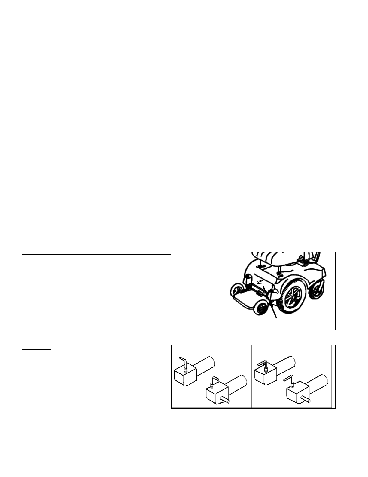
Braking Systems
The power wheelchair's brake systems allow for smooth start up and safe braking without undue
jerking. There are three (3) separate modes to the braking system: Regenerative, Dynamic, and Posi-Lock
Electric Braking. All braking occurs automatically during wheelchair operation if the joystick power is "ON".
If the joystick power is turned "OFF", the regenerative braking and dynamic braking are not functional.
WARNING: Always leave the joystick power "ON" when parked on or attempting to stop on an incline. Failur e
to leave the joystick power "ON" could result in partial loss of braking and steering control causing potential
damage to the equipment and/or harm to the rider.
Each type of braking is described in the following.
1. Regenerative Braking is activated while driving the power wheelchair down an incline. When
the wheelchair picks up speed going down the incline, the motor generates electricity. This electricity is
channeled back through the power wheelchair electronic control circuits to recharge the batteries. This action
keeps the wheelchair from picking up excess speed and provides for smooth speed control.
2. Dynamic Braking is activated WITHOUT delay when all power is stopped to the motor by bringing
the control knob back to the center position, as when coming to a complete stop. This braking works until the
Posi-Lock Electric brake is activated.
3. Posi-Lock Electric Braking Disk is activated with delay when all power is stopped to the motor. This
electric brake has a short delay and ultimately holds the power wheelchair at a complete stop. The wheelchair
cannot be moved when this brake is activated. Dynamic Braking works in conjunction with Posi-Lock Electric
Braking to bring you to a gradual and complete stop.
MOTOR/BRAKE DISENGAGE MECHANISM
The power wheelchair is equipped with Motor/Brake Disengage
lever(s). This systems allows the wheelchair to be moved in the event
the batteries are run low, or there is a malfunction. To operate the
Motor disengage mechanism, turn the power off to the wheelchair
and push the levers by the decals located near the lever(s) as shown.
The motor/brake combination is now disengaged and the wheelchair
will not operate,
but will roll freely.
Caution:
DO NOT ride the power wheelchair with
Motor/Brake Disengage Mechanism activated
since there is a strong possibility an accident with
injuries will occur. Should you experience any
type of brake system malfunction, DO NOT ride
or sit on the wheelchair. Have the system repaired
immediately!
BRAKES LOCKED
Scout RF-P3 & P4 Two Disengage Levers
Boss 4.5 Single Disengage Lever
BRAKES RELEASED
SHOULD THE BRAKE DISENGAGE ON A WHEELCHAIR EVER APPEAR TO WORK POORL Y OR
INCORRECTL Y , ST OP RIDING IMMEDIATEL Y AND CONT ACT YOUR DEALER FOR SERVICE!
18 BOSS 4.5, RF, P3 & P4 OWNERS MANUAL
Page 21
Power Seat Operation
Power Seat Operation (Not available on RF-P3 and RF-P4)
Optional power seat actuators will be operated using one of the following control systems.
Joysticks with integral actuator controls
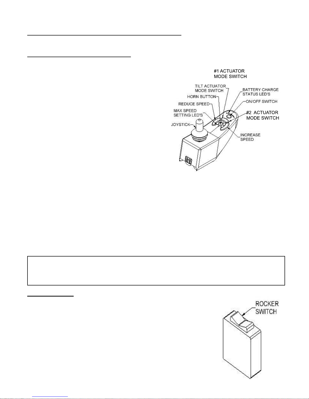
The controller has two modes of operation. One is called the “drive mode”. It is used to drive the chair.
The second mode is the “actuator control mode” used
to run up to two different motorized actuators including tilts, power seats and Stanza.
While you are in the “drive mode”, the power wheelchair controls will function as explained earlier in
this manual.
To switch from the “drive mode” to the “actuator control mode” you must have the power chair
stopped and sitting on a fi rm level surface. Find the
curved mode switch button located just under the
ON/OFF button.
Press and release the actuator control mode button to
once to toggle from drive mode to controlling motorized actuators. Then press the button a second time to light up #2 on the switch. The far right part of the
button will be lit up when the second function is active.
Moving the joystick forward will lower the seat. Pulling back on the joystick will raise the seat. The speed
is proportional and can be adjusted by how far you have moved the joystick.
Once you have fi nished adjusting the powered accessories, you may leave the “accessory power mode” and
return to drive mode by pressing and releasing the mode switch until both of the small mode switch lights
are off. If the power switch is on both mode switch lights are off you are in drive mode. Moving the joystick will cause the power chair to move.
WARNING: Before using the joystick, always look at the indicator lights to know what
mode you are in. Failure to do so could result in unexpected movement of the power chair
causing potential harm to the user and or the equipment.
External Controls
Controls that are not activated through the joystick do not require you to
toggle between “drive mode” and “actuator control power mode”.
To operate the power seat actuator with external controls, you must have the
power chair stopped and sitting on a fi rm level surface. Locate the small
black box with the rocker switch. Push at the back of the rocker switch to
raise the seat and push at the front of the rocker switch to lower the seat.
BOSS 4.5, RF, P3 & P4 OWNERS MANUAL 19
Page 22
Seat Assembly Operation
The power wheelchair comes with removable/height adjustable arms. These arms are designed to provide
support for your arms while seated on the wheelchair, and for assistance when getting on and off of the
wheelchair. Persons with no use of their legs, or no ability to transfer weight to the fl oor should seek other
means of assistance (slide board, helper, etc.) when transferring in and out of the wheelchair. Arm failure will
result if excess weight is applied to the arm.
Width adjustable arm adjustments
1. Loosen the black knobs under the edge of the seat. Rotate counter clockwise to loosen.
2. Slide the armrests in or out as needed.
3. Tighten the black knobs. Rotate clockwise to tighten.
Should you wish to remove the armrests, simply pull them out when the knobs are loose. Remember to
tighten the knobs to avoid their loss.
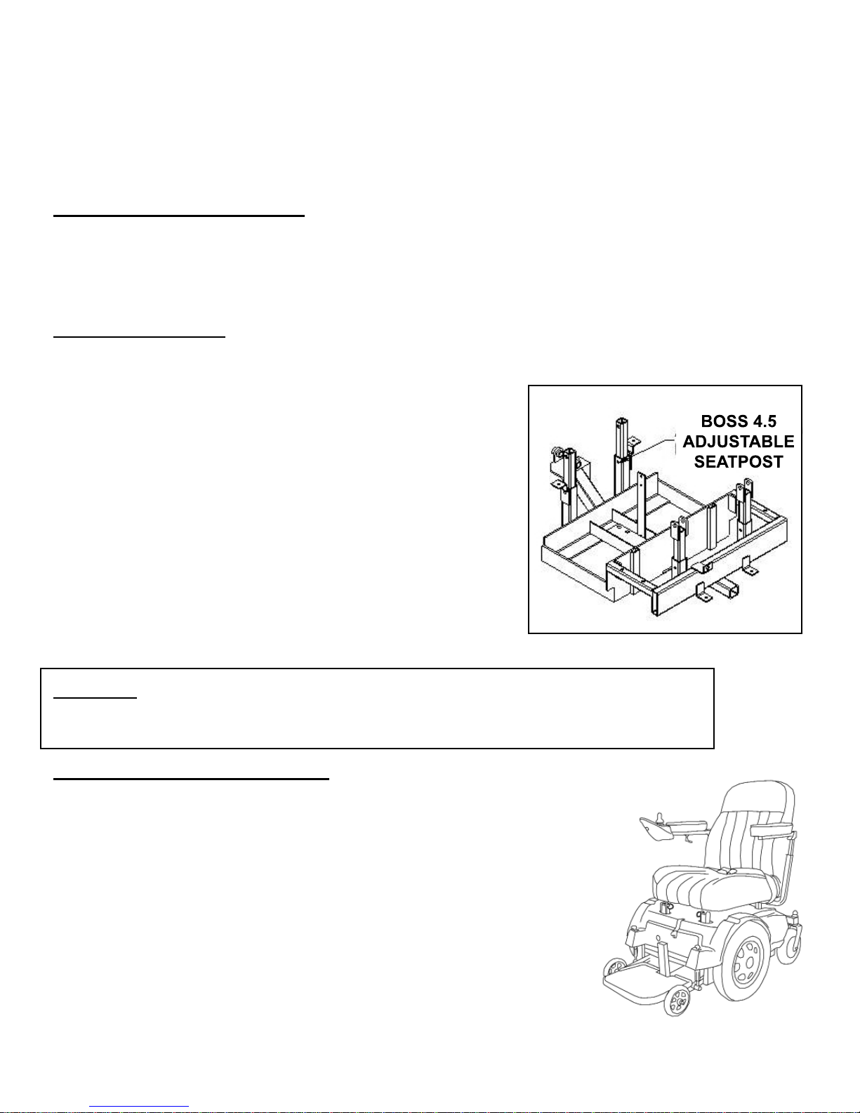
Seat Height Adjustment
NOTE: The Boss 4.5 is shown in the photo. The seat height is adjusted on the Scout RF-P3 & P4 in the same
manner.
1. Remove the seat assembly by unpinning the seat and lifting the
seat assembly straight up. Set aside.
2. Locate the seat height adjustment bolts and nut
located on the post where pins were removed.
3. Remove the bolt, nut, and washers. Take note of
their position in order to correctly replace them.
4. The seat height post will now move up and down.
5. Position the seat height to new desired position.
6. Replace the washers, bolt, and nut in their proper order.
Tighten until all play is eliminated.
7. Replace the seat assembly and test the new height.
It is recommended that the seat assembly be positioned at the lowest
comfortable seat height. The power wheelchair's stability will be
improved with a lower height.
WARNING: For units with the optional Power Seat, only drive the wheelchair when the power
seat is in the lowest position to avoid tipping and serious injury. If you are unable to follow this
instruction, consult your dealer for alternatives.
ASSEMBLING THE WHEELCHAIR
The power wheelchair's easy separation makes it very convenient to disassemble
and assemble the unit. Complete disassembly can be accomplished in seconds
WITHOUT tools. The procedure is as follows.
Make sure the power button has been placed in the off (no lights) position.
Remember, it should already be in the OFF position since it was placed there
when you last got off the wheelchair. Disconnect the power cord located at
the rear of the seat on the seat bracket, unpin the seat at all four points, lift the
seat assembly up and remove. Lift off the cover while passing the cable and
connector through the hole in the cover.
Disconnect each battery by depressing the tab on each battery plug to unplug
the cable. Remove both batteries.
20 BOSS 4.5, RF, P3 & P4 OWNERS MANUAL
Page 23
Disassembly and Assembly
Last you need to remove the Footplate/Stabilizer wheel assembly from the front of the wheelchair, by
removing the two winged bolts or pull pin holding it to the main frame assembly. Raise the front footplate
section up out of the way.
REASSEMBLING THE WHEELCHAIR
T o reassemble the wheelchair, simply repeat the same steps in reverse order. 1.) Replace the foot plate on the
frame assembly and replace the winged bolts.
WARNING never operate the unit without reattaching the front section and the bolts/wing-nuts or pull
pin which holds the front section in place!
Put the batteries in place and connect the battery cables. Align the red dots on each connector so that they
line up. Push the plug straight in until the connectors click together. Place the connectors between the
batteries.
Replace the rear cover by running the control cable through the hole in the cover and setting the cover securely on
the frame. Make sure the velcro on the cover attaches to the velcro on the rear frame support piece.
Place the seat assembly onto the four height adjustment posts. Connect the control cable to the controller.
Follow the entry instructions elsewhere in this manual, and go for a ride.
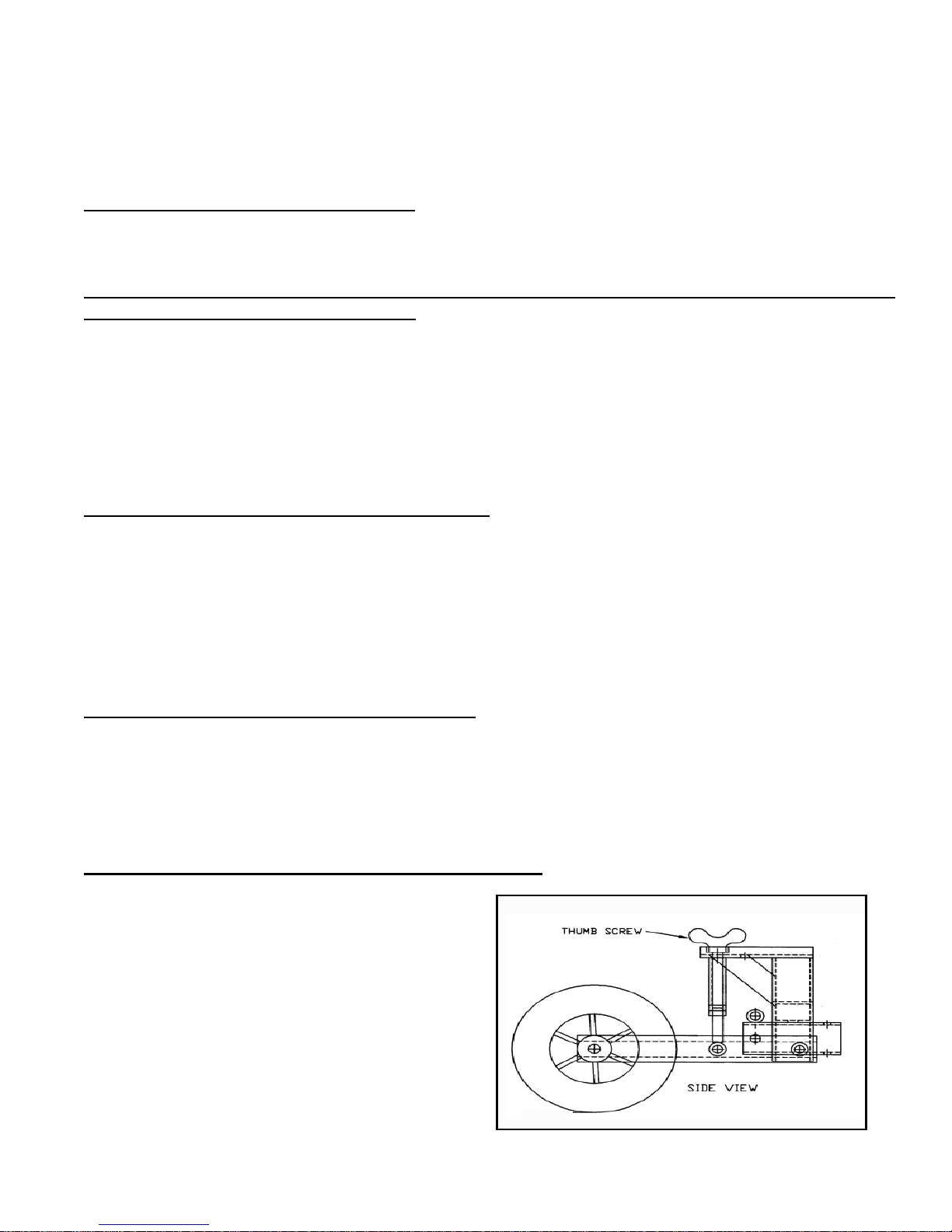
INFINITEL Y ADJUST ABLE ANTI-TIP WHEELS
The anti-tip wheels are normally positioned approximately 1/2” off the fl oor for indoor use (with a rider in
the chair) but may be adjusted in height. Because Scout Explorer is a “midi” (3/4) drive chair the anti-tip
wheels are normally only used when braking going forward down a steep incline. The lower setting causes
the powerchair to tilt forward at a lesser angle before resting on the anti-tip wheels if you decelerate rapidly
while going down a hill. See specifi cation page for maximum obstacle climbing capability. Always keep
anti-tip wheels at the same height from fl oor to prevent possible tipping to the side.
ANTI-TIP ASSEMBLY STANDARD SETTINGS
- To RAISE the wheel height, turn the thumb screw clockwise until the wheels are in the desired position.
- To LOWER the wheel height, turn the thumb screw counter-clockwise until the wheels are in the desired
position.
FINGER ADJUST ABLE FRONT ANTI-TIP ASSEMBLY
- Wheels set lower will provide additional stability
- Wheels set higher will provide additional clearance
over obstacles
BOSS 4.5, RF, P3 & P4 OWNERS MANUAL 21
Page 24

The Wheelchair Batteries
Charging the batteries is the most important part of operating and maintaining your power wheelchair. Be sure to do
it properly! IMPORTANT: Only AGM or gelcell sealed lead-acid deep cycle discharge type batteries should be
used with this wheelchair. Do not use regular car starter batteries. AGM and gelcell batteries do not require water
and they have no danger of spillage. Some are approved by the Federal Aviation Administration for air travel.
NOTICE: The battery charger provided is specially designed for use with PaceSaver brand equipment. In
the unlikely event of failure it should be replaced only with a PaceSaver approved charger to assure proper
performance of the charger and wheelchair.
Important Safety Information:
Always use caution when lead-acid batteries are being charged. Batteries can generate explosive gasses
during charging. Observe the follow guidelines to reduce risk of battery explosion.
1. Never smoke or allow open fl ame or sparks around a charging battery.
2. Never charge a frozen battery.
3. Use a PaceSaver charger designed for charging deep-cycle gelcell and AGM batteries.
4. The user is instructed to NOT use the charger with a battery confi guration not matching the output
voltage rating of the charger. The batteries in this unit are connected for 24 volts.
5.The charger is rated at 24 volts DC and includes a special safety circuit to prevent operation of the unit
while charging. This is to prevent accidently driving away with the AC cord connected, causing damage to
the cord and to the receptacle in the user's residence.
6. Do not operate the charger in closed area or restrict ventilation around the charger in any way.
7. Do not disconnect the DC portion of the charger circuit while the AC cord is still connected to the
electrical outlet.Unplug the AC cord fi rst.
8. It is normal for the charger to operate at a high temperature. Do not touch the hot charger until after it cools.
Basic Safety Instructions:
1. Do not expose the charger to rain, snow or other moisture sources (i.e., sprinkler, car wash, etc.). When
storing the unit, keep it inside a building or under a protective covering.
2. Use of the charger in a manner not recommended by the manufacturer may result in the risk of fi re,
electrical shock or personal injury.
3. To reduce the possibility of damage to the AC cord or the connector, disconnect the AC line cord by
grasping the plug and not the cord, when disconnecting from either the unit or the wall receptacle.
4. Locate cord so that it will not be stepped on, tripped over or subjected to the possibility of damage.
5. An extension cord is not recommended for use with this equipment. Use of an improperly rated extension
cord could result in risk of fi re or electrical shock. Should it be required to use an extension cord, make
certain that it is of 3-wire construction and has a wire size of at least 16-gage, and the cord must be in good
electrical condition.
6. Do not operate this charger with damaged AC cord or receptacle. If they are damaged, replace them
immediately.
7. Do not disassemble the charger. If there is a perceived problem with the equipment, refer to the servicing
section of this manual or refer to a qualifi ed technician for service. Incorrect assembly of the charger could
result in a risk of electrical shock or fi re.
8. Do not operate the charger if it has received an impact of a severity that may render it inoperative. Take it
to a service technician.
9. To reduce the risk of electrical shock, unplug the charger from the electrical outlet before attempting any
maintenance or cleaning.
10. Operate the charger on a fl at surface. Restricting air fl ow around the charger can create an overheated
condition. Carpeted fl oors can restrict air fl ow. It is normal for the charger to operate at a high temperature.
11. Do not operate the charger with a damaged cord or plug. Do not operate if the charger looks like it has
been damaged. Contact your dealer for repair.
22 BOSS 4.5, RF, P3 & P4 OWNERS MANUAL
Page 25

The Wheelchair Batteries
12. Make sure the 3-pronged charging plug is seated fully in the wheelchair battery charger outlet in the
front of the joystick.
13. Do not stand on wet surface while connecting charger.
Before Charging:
1. Verify that battery terminals are clean and that all charger connections are secure and in good condition.
2. Verify that all cords and cables are in good condition.
Grounding and AC Power Connection:
The charger must be plugged into a grounded electrical outlet. The unit is provided with an electrical cord
which contains a conductor for grounding. The charger cord must be plugged into an AC outlet that is properly
installed, and is grounded in accordance with the National Electrical Code and all local electrical codes and
ordinances.
!! CAUTION !! - Failure to plug the charger into a gr ounded receptacle could cause a condition allowing an
electrical shock hazard to be present while charging.
++DANGER++ Improper connection of the equipment grounding conductor can result in a risk of electrical
shock
!! CAUTION !! - Never alter the AC cord or plug provided with this equipment. If it does not fi t the outlet,
have a properly grounded outlet installed by a qualifi ed electrician.
A TEMPORARY AC ADAPTER may be used to connect the plug provided with this charger to a two-pole
receptacle if a properly grounded receptacle is not available. The temporary adapter should only be used until
a properly grounded outlet can be installed by a qualifi ed electrician. The green colored tab on the adapter
MUST be connected to a permanent ground such as a properly grounded outlet box.
THE USE OF TEMPORAR Y ADAPTERS IS ILLEGAL IN CANADA AND SHOULD NOT BE USED. HAVE
A QUALIFIED ELECTRICIAN INSTALL A GROUNDED OUTLET BEFORE USING THIS CHARGER.
!! CAUTION !!: Be certain the wall cor d is disconnected fr om the electrical outlet before moving the wheelchair.
Moving the wheelchair without disconnecting the wall cord could r esult in damage to the wheelchair, the cord
and the wall outlet. This could create a shock hazard condition.
++WARNING++: Because you will be connecting and disconnecting AC to the wheelchair, be cautious of doing
so in the presence of water (i.e., rain or puddled water). Electrical shock hazard could be present. Observe
all caution and safety warnings.
++WARNING++: Lead-acid batteries generate gasses which can be explosive. A void smoking, sparks or open
fl ames around charging batteries. Charge in an area with adequate ventilation.
++WARNING++: Chargers cause small sparks that can ignite fl ammable materials and gasses. Do not
use chargers near fuels, grain dust, solvents, thinners or other fl ammable materials. Charge in an area with
adequate ventilation.
Information for California Residents: Compliance with Proposition 65
Warning: This product (batteries) contains or
emits chemicals known to the state of California to cause cancer and birth defects or other
reproductive harm.
Warning: Battery posts, terminals and related
accessories contain lead and lead compounds.
Wash hands after handling.
BOSS 4.5, RF, P3 & P4 OWNERS MANUAL 23
Page 26

Useful Battery Information
1. The battery gage on the joystick console takes into account time as well as battery voltage to
provide a more accurate estimate of battery capacity while you are driving. The display simulates a bar graph
where all LED's lit represent a full state of charge and a single red LED represents the lowest state of charge.
If, while you are driving, the indicator falls into the red area, charge the batteries as soon as possible. Charging will bring deep cycle discharge condition batteries up to full charge. You will not see maximum battery
life if the batteries are routinely run to the deep cycle discharge condition.
2. It is best to charge the batteries before they reach the deep cycle discharge condition. Short
charge intervals to keep a battery “topped off” are better than long intervals for bringing a battery up from
deep cycle.
3. Keep the batteries away from heat. Areas with excessive sunshine or excessive heat will cause
a faster loss of charge in the batteries. Heat will cause the batteries to lose their charge and also shorten
their life.
4 Storage of batteries is very important to their life span. The very best way to maximize battery
life is to store them in a fully charged condition in a cool place. Then, periodically charge EVERY ONE TO
TWO MONTHS to keep the batteries in this fully charged condition. The PaceSaver charger can be left connected indefi nitely without damaging the batteries.
5. Loose connections can keep the batteries from delivering full power. Visually check the battery
wire connections in the battery box periodically for looseness. Always connect the red wire to the positive
(+) battery terminal. Connect the black wire to the negative (-) battery terminal.
6. Batteries should never be subjected to freezing temperatures. Discharged batteries can be quickly
ruined in freezing conditions.
WARNING: Do not use a non-sealed liquid lead acid battery. Spillage of battery acid will cause severe
burns and will corrode metal components of the power wheelchair.
Charging Notes:
Regular use of your chair will require regular charging. It is a common misconception that batteries need
to be run into deep discharge before recharging. This is not true and can lead to damage of the batteries if
they are regularly discharged deeply before recharge. Likewise, if batteries are stored or used for a long
period of time without recharge, this may result in permanent damage to the batteries resulting in unreliable operation and shortened battery life. Maximum driving range of your wheelchair can be obtained if
the batteries are fully charged prior to a lengthy trip. Because the charger is a fully automatic charger, it
can be "on charge" for an indefi nite period of time without harm to the batteries.
Some chargers have a small cooling fan located inside the charger which is thermostatically controlled and
may come on as internal temperatures rise. This fan may operate at regular intervals. Do not rely on it’s
operation as an indication of charger output. Battery chargers are designed to operate at a high temperature.
24 BOSS 4.5, RF, P3 & P4 OWNERS MANUAL
Page 27

Useful Battery Information
Fuse:
There are no replaceable fuses in the charger. This charger uses solid state technology to protect the unit
and the batteries until the fault has been removed.
Service/ Troubleshooting: Should your charger fail to perform:
1. First, check that all connections are properly made for a fully assembled wheelchair. On some equipment, the charger lines go through the motor plug, so if the motor plug is disconnected for some reason,
then the charger will not function. Likewise, if the batteries are not connected, they will not receive a
charge, and the meter will not give an indication.
2. Check that the wall outlet has power to it. The outlet may be on a switch and will not function if not
switched on.
If these steps fail to produce satisfactory results, please refer to an authorized service center to have the
system fully analyzed.
Tips for increasing the range of the power wheelchair:
• Reduce the weight carried on the wheelchair.
• Infl ate the tires to the recommended pressures.
• Acclerate slowly by pushing gently on the throttle.
• Set the speed control knob to about two-thirds of maximum speed.
• Travel around obstacles whenever possible.
• Periodically check that all electrical connections are secure.
Tips for maximizing the battery life and reducing total recharge time:
• Always use the PaceSaver battery charger that is provided with the wheelchair.
• Park the wheelchair in the shade whenever possible.
• Avoid discharging the batteries below the green LED zone on the battery meter,
(about 50 percent discharge level).
• Recharge until the "CHARGE" light on the charger turns of f. This would be 80 - 90 percent of full char ge.
• Every ten or so recharge cycles leave the charger connected to the batteries for a few additional
hours or overnight. This will bring the battery up to 100 percent recharge level.
• Avoid subjecting the batteries to below zero freezing conditions.
BOSS 4.5, RF, P3 & P4 OWNERS MANUAL 25
Page 28

Charging The Batteries
The switch-mode battery charger provided is specially designed for use with your PaceSaver wheelchair. In
the unlikely event of failure we recommend replacement only with a PaceSaver brand charger. The charger
is intended for use with AGM or gelcell sealed lead-acid deep cycle discharge type batteries only. This is
a 24 volt DC charger for use only with batteries connected for 24 volt DC service. Do Not use the charger
with a car starter battery.
The PaceSaver brand battery charger includes
• Microprocessor control allows switch-mode operation for faster charging.
• Light weight and compact size offers space advantages.
• All units feature Auto Voltage Select (AVS): One unit operates for 100 VAC, 120 VAC or 230 VAC.
• Power limited battery charging (using algorithm) depending on battery state of charge.
• Automatic shutoff and restart to compensate for battery self discharge.
• Reliable charging achieved through a multi-stage, multi-mode charging algorithm.
• Thermal protection prevents damage from over temperature conditions.
• Input & output protected by automotive electronic sensor.
• Output current limit so as not to exceed the maximum power and/or thermal capacity.
• Output short circuit and reverse polarity protection.
• LEDs indicate AC Power ON, Charging Status and Fault Conditions.
Refer to the maual provided with the battery charger for detailed specifi cations and operation information.
Operation
1. Ensure that the AC cord is disconnected from the supply receptacle.
2. Connect the charger output connector to the wheelchair battery connector. On the front of the SHARK
joystick controller .
3. Plug the AC line cord into a nearby outlet. Turn on wall switch (if used). The yellow light will illuminate
to indicate that AC power is present. After several seconds the green light will fl ash to indicate that charging
is in process. If no lights are illuminated, or if the yellow light fl ashes, refer to the Troubleshooting section.
Charge time will vary from less than 1 hour to over 10 hours depending on the depth of discharge of the batteries.
4. When charging is complete both the yellow and green lights will remain on and the charger will be in
standby mode. The charger is now ready to be disconnected from AC power and then from the powerchair.
Battery Charging
The satisfactory performance of the SHARK system is critically dependent on the type and state of charge
of the batteries. The PaceSaver Battery Charger used must used according to the instructions. Failure to do
so may damage or destroy the batteries, give poor range, or be potentially dangerous. Batteries should not be
abused (for example by regularly deep discharging) and must be operated and maintained according to the
instructions.
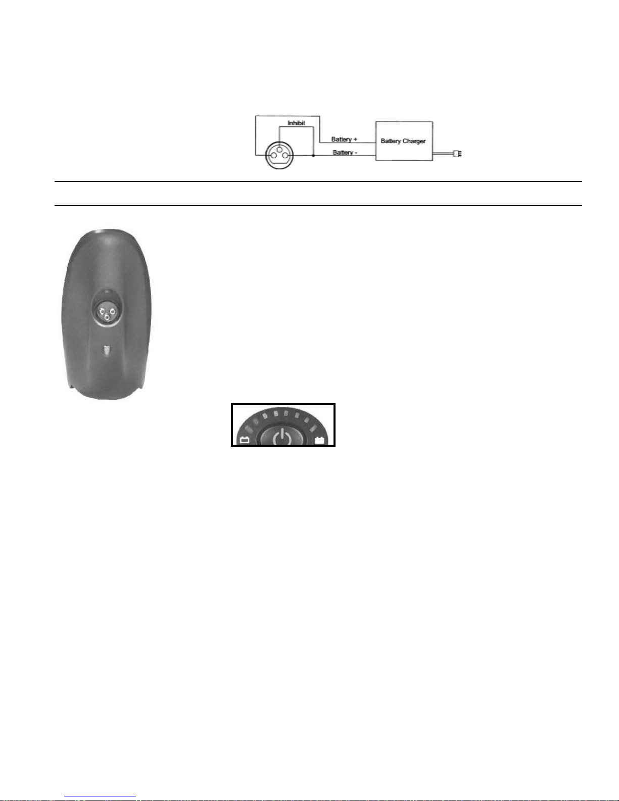
The battery charger socket is a 3 pin XLR type with pin confi guration as shown below. The PaceSaver char-
ger is compatible with this pin out. There is an inhibit safety link built into the charger so that the wheelchair is prevented from driving when the batteries are being charged. This is to prevent accidently driving
away while the AC cord is connected.
26 BOSS 4.5, RF, P3 & P4 OWNERS MANUAL
Page 29
Charging The Batteries
Warning : Do not disconnect batteries or open circuit the circuit breaker during charging. This is dangerous
to both people and equipment.
System Battery
Charger Plug
on Front of Joystick
Note : The inhibit is shorted to B- external to the System.
Plug the battery charger into the charging socket located at the front of the SHARK
joystick.
The SHARK Information Gauge will indicate the system is being charged by cycling between a left-to-right "chase" and displaying the current battery state-ofcharge.
Driving is prevented (inhibited) while the system is being charged.
Once the system status gauge displays a "full battery charge (all LED's are lit), the
battery charger plug may be removed.
Note: If the SHARK is turned off, or goes into sleep while charging, charging will
continue.
SHARK Information Gauge
The SHARK Information Gauge (located on the joystick console) is the primary source of user feedback. It
displays every possible status that SHARK may have.
• SHARK Power ON
• The battery Indicator displays the true state-of-battery-charge, including notifi cation of when the battery
desperately requires charging. The true status is most accurate only while you are driving.
• Any green LED's lit indicates well-charged batteries.
• If only yellow and red LED's are lit, the batteries are moderately charged.
They must be rechar ge before undertaking a long trip. To prolong the life of the batteries they should
be recharged at this point.
• If only red LED's remain lit the batteries are running out of charge. Recharge as soon as possible.
Frequently driving down to the red will reduce the life of the batteries.
• SHARK Lock Mode countdown.
• Program, inhibit or charge modes.
• Fault indication (Flash Codes)
BOSS 4.5, RF, P3 & P4 OWNERS MANUAL 27
Page 30
Charging The Batteries
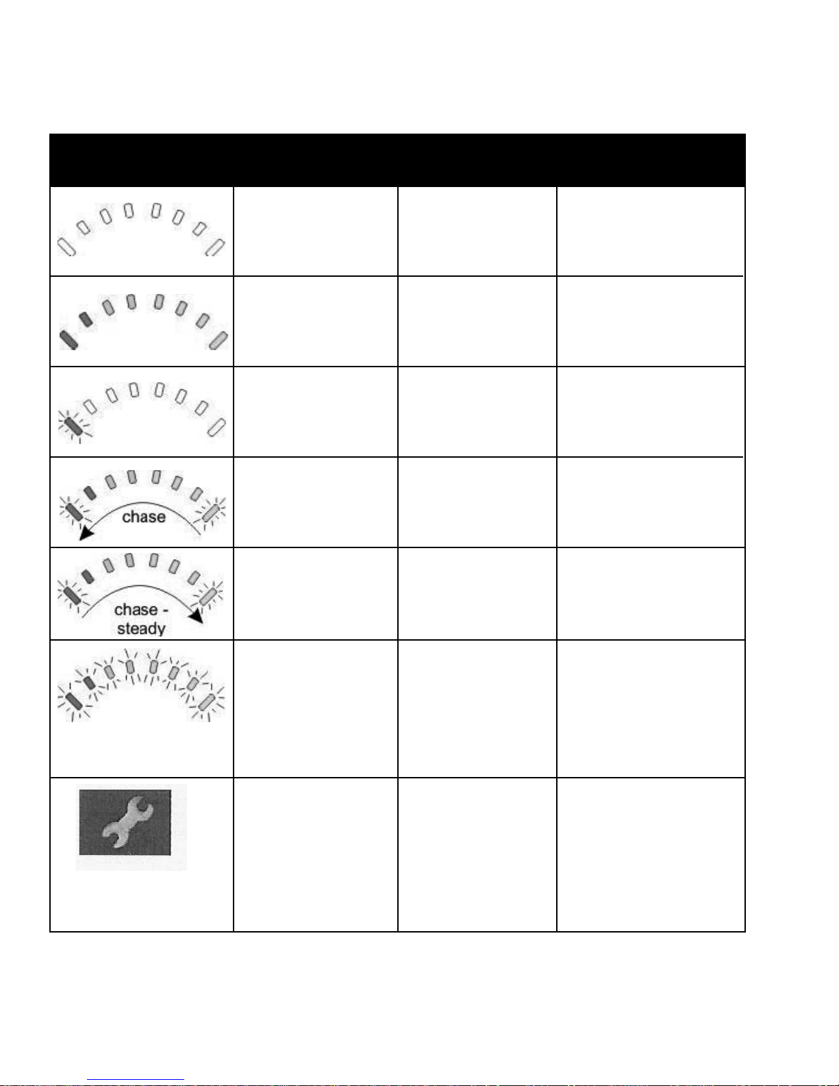
The following table indicates what the gauge will display for any given state.
All LED's OFF
Power is OFF
Display Description This means . . . Notes
All LED's ON
Power is ON
Less LED's imply
a reduced battery
charge.
Left RED LED
is fl ashing
Battery charge is
low
The batteries should
be charged as soon as
possible.
Right to left
"chase"
Left to right
"chase" alternating
with steady display
SHARK is being
brought out of
Lock mode
SHARK is in
programming,
inhibit and/or
charging mode
To unlock SHARK,
press the Horn button
twice within 10 seconds.
The steady LED's indicate the current state
of battery charge.
All LED's fl ashing
slowly
Amber Service
Indicator LED
28 BOSS 4.5, RF, P3 & P4 OWNERS MANUAL
SHARK has
detected an OUT
OF Neutral At
Power Up
(OONAPU) condition
SHARK has detected a fault
Release the joystick
back to neutral.
SHARK uses Flash
Codes to indicate
faults. For a list of
Flash Codes and what
they indicate, see Diagnostics section.
Page 31
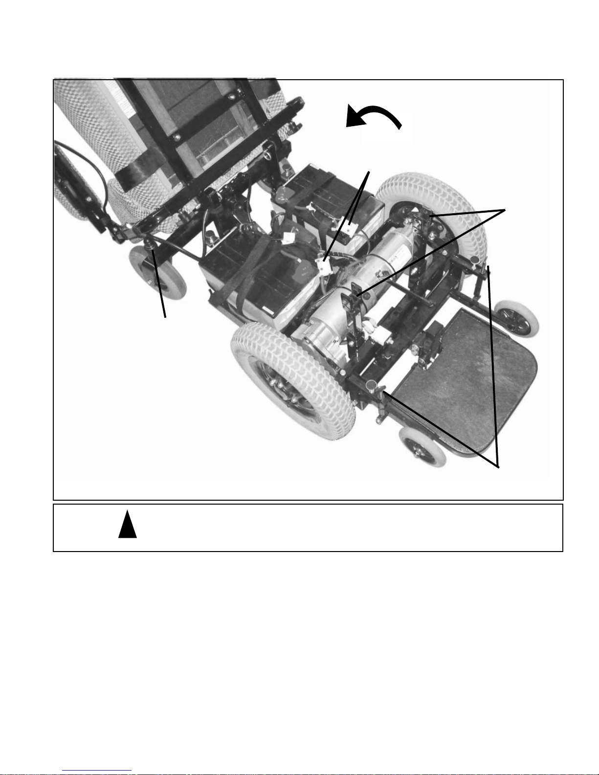
Top of
Caster
Battery Removal From Unit
FIGURE 1
Battery
Connectors
Pull Pins
NOTE: The Boss 4.5 is shown in the
photo. Batteries are removed from
the Scout RF-P3 & P4 in the same
manner.
CAUTION - Failure to unplug cable from back of joystick before tilting
!
seat back may result in damage to the joystick and cable.
1. Turn power off to controller.
2. Disconnect controller cable at back of seat
3. Remove the pull pins from the front of the seat.
4. Tilt seat rearward until seat back supports rest on the top of the casters.
CAUTION: Hold on to the joystick and the front of the seat while you tilt the seat back. Failure to do so
could result in the joystick fl opping backwards and striking the fl oor as you lower the seat resulting in dam-
age to the joystick.
5. Remove plastic shroud from unit. Be sure not to damage the controller cable.
6. Disconnect the battery connectors.
7. Remove batteries.
Anti-Tip
Adjustment
BOSS 4.5, RF, P3 & P4 OWNERS MANUAL 29
Page 32

Storage of the Power Wheelchair
Short Term and Overnight Storage
When ending power wheelchair's use for the day, if the batteries do not need charging, simply turn the power
OFF . The next morning, get in, lock the seat, activate the key , turn power ON and you are ready to go again. In
areas with public access, use of the key function will restrict powered operation of your power wheelchair.
Long Term Storage
When the power wheelchair will not be used for an extended period of time, there are several things you
should do to help maintain its proper working condition.
The powerchair and its batteries should only be stored in a dry environment with moderate temperatures.
Long term exposure to excessive hot or cold temperatures will be harmful to the life of the batteries. The
batteries must be fully charged before they are stored. We also recommend that you disconnect the battery
leads or remove the batteries from the powerbase.
Every one to two months, you should reconnect the battery leads and the charger to make sure that the batteries are still fully charged.
Maintaining the Power Wheelchair
In general, The power wheelchair is very easy to maintain. Consult your dealer if any repairs, adjustments,
or damaged part replacements are needed.
Routine Maintenance
Daily
- Charge the batteries, if required, as described in the “Charging the power wheelchair Batteries” section
of this manual.
Weekly
- Check the tire pressure for proper infl ation. (see the proper specifi cations for the wheelchair you own).
- Clean the power wheelchair using a damp cloth with a mild soap. Use a minimal amount of water. Do not
allow electrical components to get wet. Wipe dry.
Monthly
- Look the power wheelchair over in general making sure all the bolts and nuts are still tight.
- Inspect the battery and motor connections for wear, damage, and that proper connections are made.
Twice a Year
- Inspect all wheels for looseness and tire wear.
- Clean the upholstery as needed.
Yearly
- Thoroughly examine your wheelchair to look for undetected wear and other potential problems and have
problems repaired immediately. The expense involved is always less than repair bills caused by a lack of
proper maintenance. In the same way a car would not last without service, a wheelchair should be maintained
regularly.
AND REMEMBER! If you ever notice any part of your power wheelchair working in an improper or unsafe
manner, stop riding it immediately and contact your dealer to arrange repairs. Do not use your wheelchair if
there is a possibility it is not safe!
30 BOSS 4.5, RF, P3 & P4 OWNERS MANUAL
Page 33
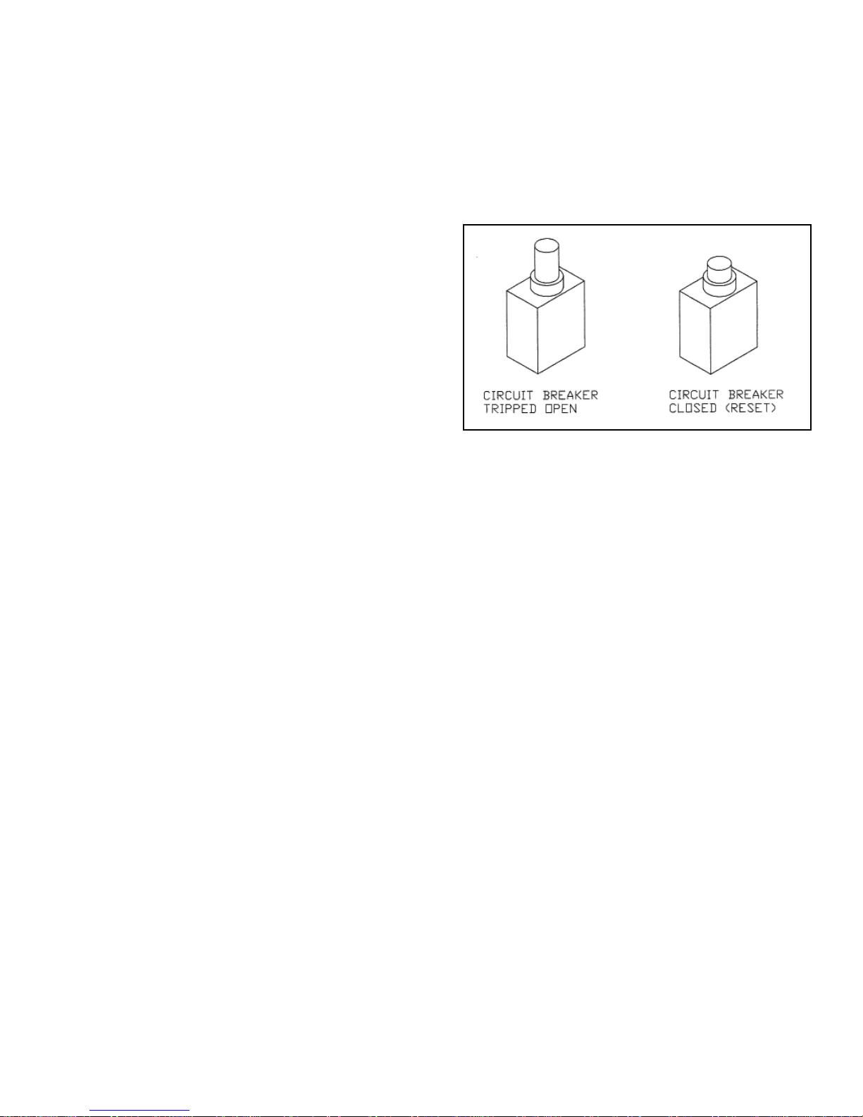
Troubleshooting
If the power wheelchair will not move, check the following.
1. Turn the power switch OFF and then back ON.
2. Check to see that the joystick console is not locked. Refer to unlocking instructions.
3. There is a visible circuit breaker. It is located on the
front of unit under the seat. You will not see any white
on the button when it is set in the correct operating position.
Also check to see that all of the wires are securely attached
to the box.
4. Check the joystick console plug (located at the rear of
the seat) for proper connection.
5. Check the battery plugs for proper connections.
6. Check the BATTERY indicator for discharged batteries.
7. Turn the power switch OFF and then back ON a second time.
8. If the wheelchair still will not move, check the LED status indicator to see if it indicates a fault and consult
the diagnostic section of this manual or contact your dealer.
BOSS 4.5, RF, P3 & P4 OWNERS MANUAL 31
Page 34

DIAGNOSTICS
Note: SHARK is not user serviceable. Specialized tools are necessary for the r epair of any SHARK component.
INTRODUCTION
A fl ashing SHARK information gauge indicates there is an abnormal condition somewhere on the powerchair. The
components that SHARK provides fault information for include, the motor, the park brakes, the batteries, the cabling and the SHARK modules themselves.
Note that joystick OONAPU (Out OF Neutral At Power Up) is not a fault. Simply by removing your hand from the
joystick and allowing it to return to the neutral position, the fault will immediately clear.
The nature of the abnormal condition is indicated by a fl ash code. This is a sequence of fl ashes, separated by a
pause, followed by a repetition of the sequence. The number of fl ashes relates to the condition. For instance, two
fl ashes of the SHARK information gauge, a pause, followed by two fl ashes, etc. indicates a Battery fault. Five or six
fl ashes would indicate a park brake fault.
Depending on the severity of the condition, the powerchair may or may not allow driving. In some cases the chair
may be allowed to drive but in a reduced speed ("limp") mode.
DIAGNOSTICS & FAULTS
Flash codes indicate the nature of an abnormal condition directly from the SHARK
Information Gauge. Without the use of any servicing tools, the condition can be simply
diagnosed. Refer to the "A" and "B" labels on the motor connector and on the Shark power
module to identify which side of the motor might be causing a problem. When checking connections make
sure that all of the pins with wires connected in the plugs are pushed all of the way in.
CODE DESCRIPTION CORRECTION
1 User Fault Possible stall timeout or user error.
Release the joystick to neutral and try again.
2 Battery Fault Check the batteries and cabling.
Try charging the batteries.
Batteries may require replacing.
3 "A" Motor Fault
4 "B" Motor Fault
5 "A"
6 "B"
Motor Park Brake Fault Check the "A" (B for Boss unit) motor brake, connections and cabling.
Motor Park Brake Fault Check the "B" (A for Boss unit) motor brake, connections and cabling.
7 SHARK
(B for Boss unit) Check the motor labeled "A" (B for Boss unit), connections and cabling.
(A for Boss unit) Check the motor labeled "B" (A for Boss unit), connections and cabling.
Check the SHARK Communications Bus connections and wiring.
Joystick Console Fault Replace the Joystick Console.
8 SHARK Check SHARK connections and wiring
Power Module Fault Replace the Power Module.
9 SHARK Check Battery voltage is greater than 17V.
Communications Fault Check the SHARK Bus cable.
Replace the SHARK Power Module.
Replace the SHARK Joystick Console.
10 Unknown Fault Check all connections and wiring.
11 Incompatible Wrong type of Control Unit connected.
System Components
Ensure the branding of the Power Module matches the Joystick Console.
If the light continues to fl ash after following the procedures in the LED Diagnostic Code chart, do
not ride the wheelchair. Notify your dealer for repair.
32 BOSS 4.5, RF, P3 & P4 OWNERS MANUAL
Page 35

Commonly Asked Questions and Possible Answers
Why has there been a sudden loss of power?
1. Undercharged batteries. Check the BATTERY indicator. The BATTERY indicator indicates the charge
condition of the batteries while you are driving. The indicator will not indicate the “true condition” of
their capacity until the wheelchair has been setting on, in an idle condition, for several minutes. The green
area corresponds to a good charge. The red area corresponds to a low charge, or a deep cycle condition.
It is possible to drive the wheelchair with the batteries in a deep cycle charge condition, but once they
drop below a certain level of power, they will fail and you will be stranded. If, while you are driving,
the indicator falls into the red area, charge the batteries as soon as possible. Charging will bring deep
cycle condition batteries up to full charge. You will not receive maximum battery life if the batteries are
routinely run to the deep cycle condition.
2. Under-infl ated tires. Check for proper infl ation (check the specifi cations for your particular
wheelchair).
3. Excessive weight on the wheelchair. Refer to the specifi cation chart for the maximum rider
weight.
4. There may be other motor or driving mechanism malfunctions. Consult with your dealer.
Will storing the batteries for a long time damage them?
Yes. Storage of batteries is very important to their life span. The very best way to maximize battery
life is to store them in a fully charged condition in a cool place. Then periodically ( every 1-2 months!)
charge to keep the batteries in this full charge condition. Do not store in cold or freezing temperatures.
Batteries should never be subjected to freezing temperatures. Undercharged batteries can be ruined quickly
in freezing conditions.
Can a regular liquid lead-acid battery be used, like in a car?
No! A DEEP CYCLE battery must be used. A car battery is not deep cycle. Deep cycle batteries
(house type batteries) are available in both AGM suspended liquid lead-acid and gel cell lead-acid. Either
type can be used. These batteries are maintenance free and have no danger of spillage. They are also
approved by the Federal Aviation Administration for air travel. Do not use a conventional liquid lead-acid deep
cycle battery. Spillage of the battery acid can cause severe burns and will damage many components of your
power wheelchair . The PaceSaver charger which came with the power wheelchair is designed specifi cally
to charge deep cycle batteries.
Why will my Power Wheelchair not climb an incline?
1. Excessive weight on the wheelchair for the grade of the incline. Refer to the Ramp Incline Chart in
this Owner’s Manual.
2. Batteries not fully charged, or are bad. Charge them and have them tested.
3. Under-infl ated tires.
Again, thank you for your purchase of a power wheelchair. We hope that you will enjoy many
years of trouble free service and freedom on your new wheelchair. Remember, your investment
and your safety depend upon following the guidelines and suggestions contained in this manual.
BOSS 4.5, RF, P3 & P4 OWNERS MANUAL 33
Page 36
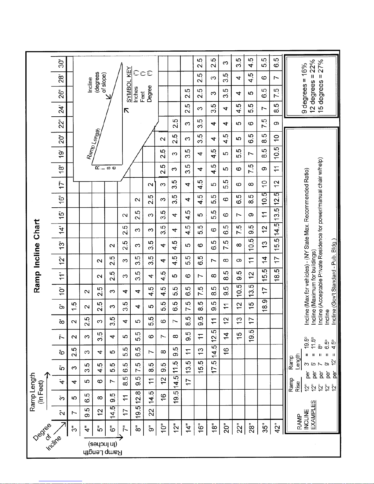
Ramp Incline Chart
34 BOSS 4.5, RF, P3 & P4 OWNERS MANUAL
Page 37

Electromagnetic Interference
EFFECTIVE DECEMBER 2, 1994 THE FEDERAL GOVERNMENT REQUIRES
THIS STATEMENT TO BE INCLUDED.
ELECTROMAGNETIC INTERFERENCE
CAUTION: IT IS VERY IMPORTANT THAT YOU READ THIS INFORMATION REGARDING THE
POSSIBLE EFFECTS OF ELECTROMAGNETIC INTERFERENCE ON YOUR POWERED
WHEELCHAIR.
Electromagnetic Interference (EMI) From Radio Wave Sources
Powered wheelchairs and motorized scooters (in this text, both will be referred to as powered wheelchairs)
may be susceptible to electromagnetic interference (EMI), which is interfering to electromagnetic energy
(EM) emitted from sources such as radio stations, TV stations, amateur radio (HAM) transmitters, two-way
radios, and cellular phones. The interference (from radio wave sources) can cause the powered wheelchair
to release its brakes, move by itself, or move in unintended directions. It can also permanently damage the
powered wheelchair's control system. The intensity of the interfering EM energy can be measured in volts per
meter (v/m). Each powered wheelchair can resist EMI up to a certain intensity. This is called its "immunity
level." The higher the immunity level, the greater the protection. At this time, current technology is capable
of achieving at least a 20 v/m immunity level, which would provide useful protection from the more common
sources of radiated EMI.
There are a number of sources of relatively intense electromagnetic fi elds in the everyday environment. Some
of these sources are obvious and easy to avoid. Others are not apparent and exposure is unavoidable. However,
we believe that by following the warnings listed below, your risk to EMI will be minimized.
The sources of radiated EMI can be broadly classifi ed into three types:
1) Hand-held portable transceivers (transmitters-receivers) with the antenna mounted directly
on the transmitting unit. Examples include: citizens band (CB) radios, "walkie talkie," sec urity, fi re, and police transceivers, cellular telephones, and other personal communication
devices. **NOTE: Some cellular telephones and similar devices transmit signals while they
are ON, even while not being used;
2) Medium-range mobile transceivers, such as those used in police cars, fi re trucks, ambulances,
and taxis. These usually have the antenna mounted on the outside of the vehicle; and
3) Long-range transmitters and transceivers, such as commercial broadcast transmitters (radio
and TV broadcast antenna towers) and amateur (HAM) radios.
NOTE: Other types of hand-held devices, such as cordless phones, laptop computers, AM/FM radios, TV sets,
CD players, and cassette players, and small appliances, such as electric shavers and hair dryers, so far as we
know, are not likely to cause EMI problems to your powered wheelchair.
BOSS 4.5, RF, P3 & P4 OWNERS MANUAL 35
Page 38

Electromagnetic Interference
Powered Wheelchair Electromagnetic Interference (EMI)
Because EM energy rapidly becomes more intense as one moves closer to the transmitting antenna (source), the
EM fi elds from hand -held radio wave sources (transceivers are of special concern). It is possible to unintention-
ally bring high levels of EM energy very close to the powered wheelchair's control system while using these
devices. This can affect powered wheelchair movement and braking. Therefore, the warnings listed below are
recommended to prevent possible interference with the control system of the powered wheelchair.
WARNINGS
Electromagnetic interference (EMI) from sources such as radio and TV stations, amateur radio (HAM) transmitters, two-way radios, and cellular phones can affect powered wheelchairs and motorized scooters. Following the
warnings listed below should reduce the chance of unintended brake release or powered wheelchair movement
which could result in serious injury.
1) Do not operate hand-held transceivers (transmitters-receivers), such as citizens band (CB) radios,
or turn ON personal communications devices, such as cellular phones, while the powered wheelchair is
turned ON;
2) Be aware of nearby transmitters, such as radio or TV stations, and try to avoid coming close to
them;
3) If unintended movement or brake release occurs, turn the powered wheelchair OFF as soon as it is
safe;
4) Be aware that adding accessories or components, or modifying the powered wheelchair, may make
it more susceptible to EMI (Note: There is no easy way to evaluate their effect on the overall immunity of the
powered wheelchair); and
5) Report all incidents of unintended movement or brake release to the powered wheelchair manufacturer, and note whether there is a source of EMI nearby.
Important Information
1) 20 volts per meter (v/m) is a generally achievable and useful immunity level against EMI
(as of May 1994) (the higher the level, the greater the protection).
2) This model of PaceSaver Scout power wheelchair has an immunity level of
meter (20 v/m).
20 volts per
The immunity level of this model of PaceSaver Scout power wheelchair is unknown.
36 BOSS 4.5, RF, P3 & P4 OWNERS MANUAL
Page 39

Scout Boss 4.5, RF-P4 & RF-P3 Limited Warranty
Leisure-Lift, Inc. will repair or replace at its option to the original PURCHASER , or to the DEALER any of the
following components found upon examination by an authorized representative of Leisure-Lift, Inc. to be defective in
material and/or workmanship under normal use and service for a period of . . .
Lifetime Limited Warranty on any structural frame components.
T wo Year Limited Warranty from date of purchase on any of the electronic parts.
Year One 100% (parts cost only)
Year Two 50% (parts cost only)
T wo Year Limited Warranty on any of the motor and gearbox parts (except motor brushes & brake pads.)
Year One 100% (parts cost only)
Year Two 50% (parts cost only)
Six Month Warranty on any plastic components (except body shroud), rubber components, bearings
and bushings, casters and anti-tip wheels.
The Manufacturer's Authorized Dealers can perform warranty service. Parts or components should not be returned to
the Manufacturer without prior consent. All transportation cost and shipping damage incurred while submitting parts
for repair or replacement are the responsibility of the original purchaser.
All parts that are defective, as determined by the factory, will be replaced free of charge within the warranty period
(see above warranties for details). This Warranty from Leisure-Lift DOES NOT INCLUDE LABOR, either at your
home or at your dealer’s place of business. During the warranty period, Leisure-Lift, Inc. may, at its discretion, determine it is necessary to return the Scout Power Wheelchair to the factory for repair. Leisure-Lift, Inc. will provide parts
and labor, at our factory, free of charge for problems considered to be covered under our warranty. The customer is
responsible for all freight charges if the power wheelchair is shipped to the factory.
Failure to properly service the power wheelchair at the intervals prescribed by the owners manual, abuse or faulty
service may void this limited warranty and can result in charges for parts and service. All rights under this limited
warranty must be exercised within 20 days after the end of the warranty.
Warranty Exclusions:
• ABS plastic shrouds.
• Batteries (The battery manufacturer covers battery warranty. Leisure-Lift, Inc. does not warrant batteries).
• Tires and Tubes
• Upholstery (seating)
• Repairs and/or modifi cations made to any part without specifi c consent from the Manufacturer.
• Circumstances beyond the control of the Manufacturer.
• Damage resulting from operation other than the intended use of the product.
• Damaged Caused By:
Battery fl uid spillage or leakage
Abuse, misuse, accident or negligence
Improper operation, maintenance or storage
Commercial use or use other than normal
• A change in noise level , particularly relative to motors and gearboxes does not constitute a defect.
Such devices will inherently exhibit a change in noise level as they wear.
THERE IS NO EXPRESS WARRANTY. IMPLIED WARRANTIES, INCLUDING THOSE OF MERCHANTABILITY AND
FITNESS FOR A PARTICULAR PURPOSE, ARE LIMITED TO ONE YEAR FROM THE DATE OF PURCHASE AND TO
THE EXTENT PERMITTED BY THE LAW. ANY AND ALL IMPLIED WARRANTIES ARE EXCLUDED. THERE IS NO
EXCLUSIVE REMEDY. LIABILITIES FOR CONSEQUENTIAL DAMAGES UNDER ANY AND ALL WARRANTIES ARE
EXCLUDED.
Warranty cards should be completed and returned by the original purchaser to the Manufacturer in a timely manner.
Leisure-Lift® and PaceSaver® are registered trademarks. Scout™, Boss 4.5™, RF-P3™, RF-P4™ and Com-For-Back™ are
all trademarks of Leisure-Lift®, Inc.
© 2005 Leisure-Lift®, Inc. All rights reserved.
BOSS 4.5, RF, P3 & P4 OWNERS MANUAL 37
Page 40

Dear Friend:
Thank you so much for your purchase of a PaceSaver Scout power wheelchair! We value your trust
in us and we will do everything we can to keep you happy. You're in a special group now. Thousands of
people before you have trusted Leisure-Lift to provide them with the highest quality mobility products available. They and you have made PaceSaver the most valuable power wheelchair around.
We hope that you have read the Owners Manual completely, and that you understand all of the safety
precautions and recommendations that apply to your particular power wheelchair. If you have any questions,
please ask your PaceSaver dealer. They can help explain any points that you do not understand.
In addition, your dealer will be glad to help you with any of your other PaceSaver needs. Situated
close to you, they are in the best position to provide you with assistance and service.
The enclosed warranty card must be fi lled out in order for Leisure-Lift to:
1. effectively warranty your product in case of a problem
2. to properly follow the guidelines laid down by the Food & Drug Administration and to
3. allow us to locate you in the event of a product recall or modifi cation
We also ask several questions about you to help us better understand the needs of our customers. The
information you provide us helps to keep our power wheelchairs at the leading edge of quality and functionality and we hope that we can count on you to help us. Leisure-Lift always values the options of our customers and you may write us at any time to relate to us your "PaceSaver Experience" good (or not so good).
REMEMBER. . .
It is in your best interest to see that you (not your dealer) properly complete this card and see that it is returned to Leisure-Lift.
Yes, I want to register my warranty and apply for my
“EXTENDED LIMITED WARRANTY”!
I have
1. Enclosed my proof of purchase and
2. Completely fi lled out the registration information below.
Please send me my Warranty Certifi cate by return mail. I understand that I must have the
certifi cate to receive extended coverage and that if I do not receive my warranty certifi cate
within 30 days, I should contact the dealership from whom I purchased the unit.
DEALER NAME (if different from above)______________________
YOUR NAME ____________________________________________
ADD1 _________________________________________________
ADD2 ___________________________________________________
CITY, ST, ZIP ____________________________________________
PHONE______/____________________ Date Purchased __/__/___
YES, please send me my Extended Warranty Certifi cate.
I certify that I have read and understand the owners
manual and all of the safety information contained within.
(sign)
To help us better understand our customers, we would like to know a
little about you. Please fi ll in all the information you can.
AGE:______ WEIGHT: _____________ HEIGHT:___________
40 BOSS 4.5, RF, P3 & P4 OWNERS MANUAL
Cut along dotted line
For Service Call
Dealer:
City, St,:
Your Serial Number is:
This Warranty has been sponsored by my dealer
 Loading...