

Pacer PMO13505 Technical data

PRODUCT NAME:
PRODUCT NO.:
DATE:
1.0 inch 128X64 dots Yellow OLED
PMO13505
CUSTOMER
APPROVED BY
Pacer International
- 1 - REV.: A02 2007/08/23
REVISION RECORD
REV. REVISION DESCRIPTION REV. DATE REMARK
X01 INITIAL RELEASE 2007. 07. 04
X02 ■ Add the operating conditions for
different luminance
■ Add the panel electrical specifications
■ Add the application circuit
A01 ■ Transfer from X version
■ Add the information of module weight
■ Add the packing specification
2007. 07. 27 Page 6, 7, 8 &
18
2007. 08. 08 Page 5 & 21
A02 ■ Modify luminance specifications 2007. 08. 23 Page 6 & 8
- 2 - REV.: A02 2007/08/23
CONTENTS
ITEM PAGE
1. SCOPE
2. WARRANTY
3. FEATURES
4. MECHANICAL DATA
5. MAXIMUM RATINGS 6
6. ELECTRICAL CHARACTERISTICS
6.1 D.C ELECTRICAL CHARACTERISTICS
6.2 ELECTRO-OPTICAL CHARACTERISTICS
7. INTERFACE
7.1 FUNCTION BLOCK DIAGRAM
7.2 PANEL LAYOUT DIAGRAM
7.3 PIN ASSIGNMENTS
7.4 GRAPHIC DISPLAY DATA RAM ADDRESS MAP
7.5 INTERFACE TIMING CHART
8. POWER ON / OFF SEQUENCE & APPLICATION CIRCUIT 17
8.1 POWER ON / OFF SEQUENCE
8.2 APPLICATION CIRCUIT
8.3 COMMAND TABLE
9. RELIABILITY TEST CONDITIONS
10. EXTERNAL DIMENSION 20
11. PACKING SPECIFICATION
12. APPENDIXES
4
4
4
5
7
9
19
21
22
- 3 - REV.: A02 2007/08/23

1. SCOPE
This specification is to define the general provisions and quality requirements
that apply to the supply of display cells manufactured by RiTdisplay. This
document, together with the Module Ass’y Drawing, is the highest-level
specification for this product.
2. WARRANTY
RiTdisplay warrants that the products delivered pursuant to this specification (or
order) will conform to the agreed specifications for twelve (12) months from the
shipping date ("Warranty Period"). RiTdisplay is obligated to repair or replace
the products which are found to be defective or inconsistent with the
specifications during the Warranty Period without charge, on condition that the
products are stored or used as the conditions specified in the specifications.
Nevertheless, RiTdisplay is not obligated to repair or replace the products
without charge if the defects or inconsistency are caused by the force majeure
or the reckless behaviors of the customer.
After the Warranty Period, all repairs or replacements of the products are
subject to charge.
3. FEATURES
‐ Small molecular organic light emitting diode
‐ Color : Yellow
‐ Panel matrix : 128*64
‐ Driver IC : SSD1325T6R1 (16 Gray scale)
‐ Excellent quick response time.
‐ Extremely thin thickness for best mechanism design : 1.61mm
‐ High contrast : 2000:1
‐ Wide viewing angle : 160
‐ 8-bit 6800-series parallel interface, 8-bit 8080-series parallel interface,
serial peripheral interface
‐ Wide range of operating temperature : -40 to 70 °C
‐ Anti-glare polarizer.
- 4 - REV.: A02 2007/08/23
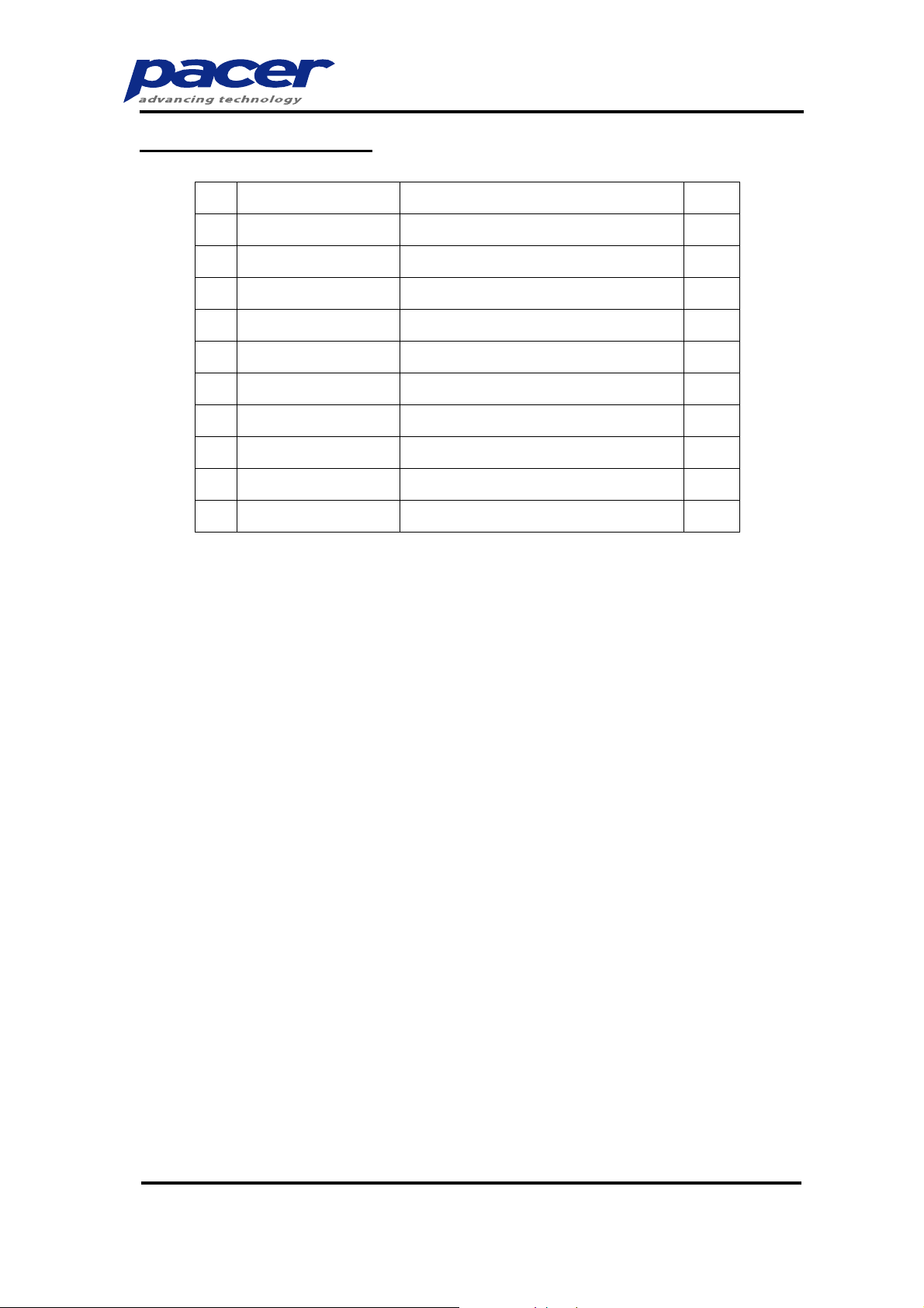
4. MECHANICAL DATA
NO ITEM SPECIFICATION UNIT
1 Dot Matrix 128 (W) x 64 (H) dot
2 Dot Size 0.15 (W) x 0.17 (H) mm
3 Dot Pitch 0.17 (W) x 0.19 (H) mm
4 Aperture Rate 79 %
5 ActiveArea 21.74 (W) x 12.14 (H) mm
6 Panel Size 29.6 (W) x 19.7 (H) mm
2
2
2
2
7 Panel Thickness
1.61 ± 0.1
mm
8 Module Size 29.6 (W) x 34.1 (H) x 1.61(D) mm
9 DiagonalA/Asize 1.0 inch
10 Module Weight
2.01 ± 10%
gram
3
- 5 - REV.: A02 2007/08/23

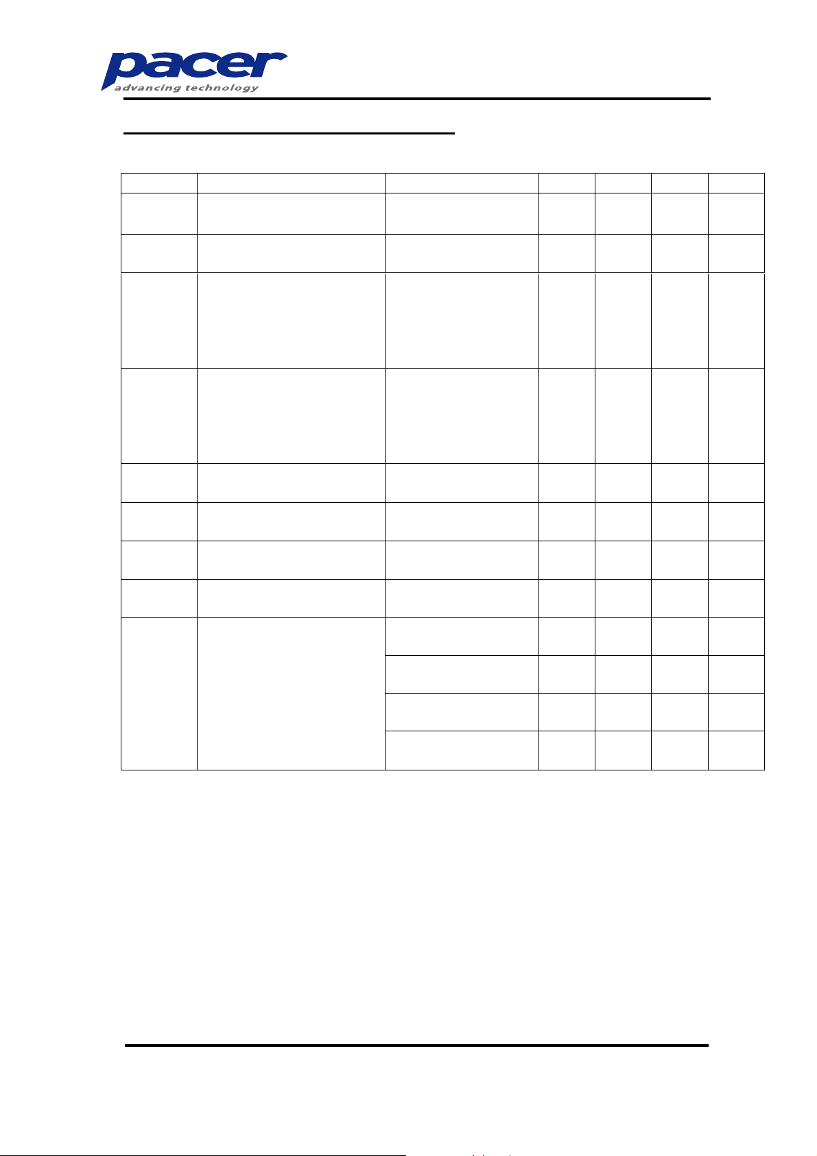
5. MAXIMUM RATINGS
ITEM MIN MAX UNIT Condition Remark
Supply Voltage (VDD) -0.3 3.5 V Ta = 25°C
Supply Voltage (Vcc) 8 16 V Ta = 25°C
Operating Temp. -40 70 °C
StorageTemp -40 85 °C
Humidity - 85 %
IC maximum
rating
IC maximum
rating
Life Time 29,000 - Hrs
110 cd/m², 50%
Note (1)
checkerboard
Life Time 35,000 - Hrs
90 cd/m², 50%
Note (2)
checkerboard
70 cd/m², 50%
Life Time 45,000 - Hrs
Note (3)
checkerboard
Note:
(A) Under Vcc = 12V, Ta = 25°C, 50% RH.
(B) Life time is defined the amount of time when the luminance has decayed
to less than 50% of the initial measured luminance.
(1) Setting of 110 cd/m² :
- Contrast setting : 0x6e
- Frame rate : 105Hz
- Duty setting : 1/64
(2) Setting of 90 cd/m² :
- Contrast setting : 0x59
- Frame rate : 105Hz
- Duty setting : 1/64
(3) Setting of 70 cd/m² :
- Contrast setting : 0x44
- Frame rate : 105Hz
- Duty setting : 1/64
- 6 - REV.: A02 2007/08/23
6. ELECTRICAL CHARACTERISTICS
6.1 D.C ELECTRICAL CHARACTERISTICS
SYMBOL PARAMETERS TEST CONDITION MIN TYP MAX UNIT
V
CC
Analog power supply
(for OLED panel)
Ta=-20 C to +70C 11.5 12 12.5 V
V
I
I
V
V
V
V
I
SEG
DD
DD
CC
OH
OL
Digital power supply Ta=-20 C to +70C 2.4 2.7 3.5 V
Operating current for V
DD
VDD= 2.7V, VCC= 12V,
IREF = 10uA
Contrast=7F - - 650 uA
No panel attached,
All Display ON
Operating current for V
CC
VDD= 2.7V, VCC= 12V,
IREF = 10uA
Contrast=7F - 700 - uA
No panel attached,
All Display ON
Hi logic input level
IH
Low logic input level 0 -
IL
Hi logic output level
0.8*
V
DD
0.9*
V
DD
- V
- V
Low logic output level 0 Segment on output
current
VDD=2.7V, VCC=12V,
IREF=10uA, Display on,
Segment
pin under test is
connected with a
20K resistive load to V
SS
Contrast=7F - 300 370 uA
Contrast=5F - 225 - uA
Contrast=3F - 150 - uA
Contrast=1F - 75 - uA
DD
0.2*
V
DD
DD
0.1*
V
DD
V
V
V
V
- 7 - REV.: A02 2007/08/23
6.2 ELECTRO-OPTICAL CHARATERISTICS
PANEL ELECTRICAL SPECIFICATIONS
PARAMETER MIN TYP. MAX UNITS COMMENTS
Normal mode current 7 9 mA All pixels on (1)
Standby mode
current
Normal mode power
consumption
Standby mo
consumption
1 2 mA
84 108 mW All pixels on (1)
12 24 mW
Normal Luminance 70 90 cd/m
Standby Luminance 10 cd/m
CIEx (Yellow) 0.43 0.47 0.51
CIEy (Yellow) 0.45 0.49 0.53
Standby mode
10% pixels on (2)
Standby mode
10% pixels on (2)
2
Display Average
2
Display Average
x, y (CIE 1931)
Dark Room Contrast 2000:1
ViewingAngle 160 degree
Response Time 10 μs
(1) Normal mode condition :
- Driving Voltage : 12V
- Contrast setting : 0x59
- Frame rate : 105Hz
- Duty setting : 1/64
(2) Standby mode condition :
- Driving Voltage : 12V
- Contrast setting : 0x00
- Frame rate : 105Hz
- Duty setting : 1/64
-
- 8 - REV.: A02 2007/08/23
 Loading...