

Page 1

R20 SPORT TREADMILL USER MANUAL
Model Number: PM810
Activate Your Warranty: www.pacemaster.com/registration
IMPORTANT: READ AND SAVE THIS MANUAL
Customer Service Team:
888-699-8918
www.pacemaster.com/help
[email protected]
Page 2

Page 3

PAGE 3 PACEMASTER R20 SPORT TREADMILL USER MANUAL
TABLE OF CONTENTS
Before You Begin 4
Important Safety Instructions 5
Assembly 6-10
Basic Assembly Tips
Assembly Steps
Treadmill Operation and Adjustments 11-16
Console Overview
Screen Overview
Using The Safety Key
Moving The Treadmill
Heart Rate Monitor 17
Maintenance 18-19
Troubleshooting 20-21
Parts List 22
Exploded Diagrams 23-25
Warranty Information 26
Ordering Replacement Parts 27
Page 4
PAGE 4 PACEMASTER R20 SPORT TREADMILL USER MANUAL
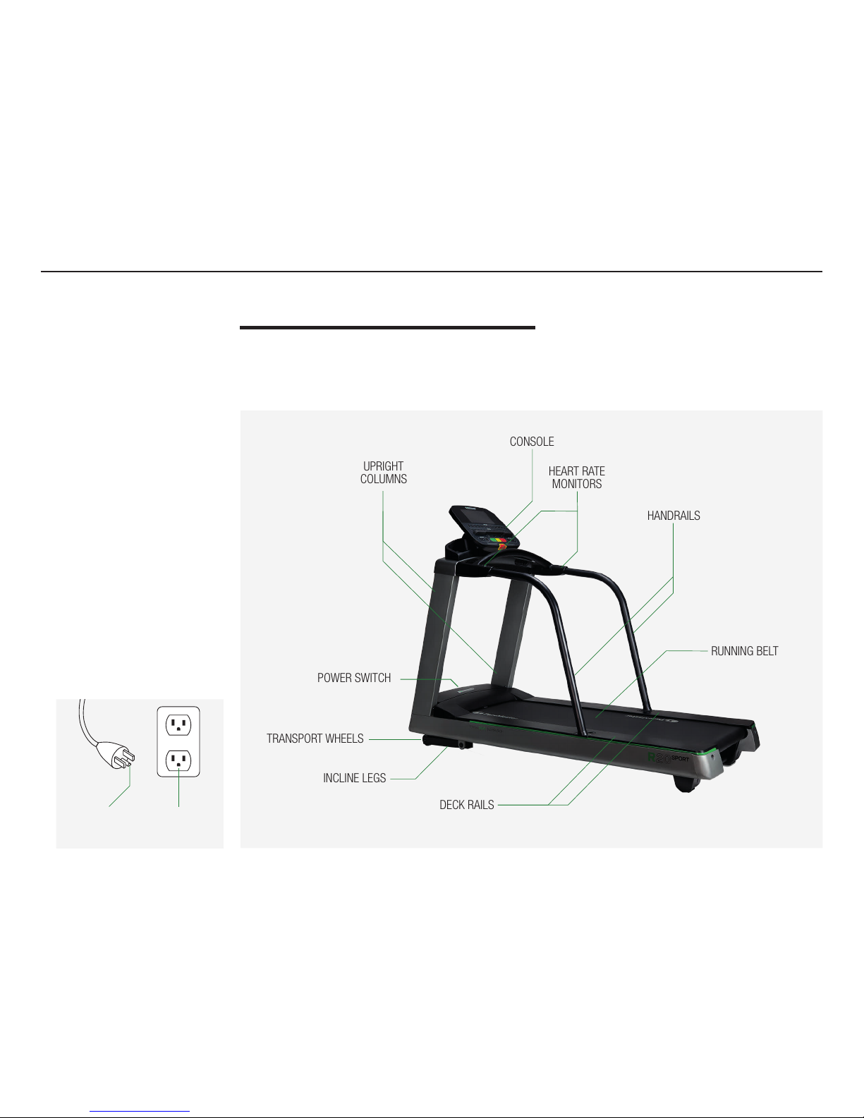
HANDRAILS
RUNNING BELT
HEART RATE
MONITORS
CONSOLE
TRANSPORT WHEELS
INCLINE LEGS
UPRIGHT
COLUMNS
DECK RAILS
POWER SWITCH
BEFORE YOU BEGIN
TREADMILL TERMS
Thank you for selecting PaceMaster R20 Sport Treadmill. Read this manual
carefully before using the treadmill. If you have questions after reading this
manual, please contact us.
GROUNDING
PIN
GROUNDED
OUTLET
Page 5

PAGE 5 PACEMASTER R20 SPORT TREADMILL USER MANUAL
IMPORTANT SAFETY
INSTRUCTIONS
It is the responsibility of the owner to ensure
that all users of this treadmill are adequately
informed of all warnings and precautions.
This equipment is rated and designed for
in-home use. Non-residential use may impact
the product warranty.
Set up and use the treadmill indoors and keep it
away from humid environments, i.e. swimming
pools, hot tubs, etc.
Place the assembled treadmill on a at surface, with
at least 2.4 meters (7.9 feet) of space behind it and
0.6 meters (2 feet) on either side. Do not position
the treadmill in a location that will block ventilation
openings. Place the treadmill on a mat to avoid
marks to oors and carpets.
Do not operate the treadmill where aerosol
products are used or where oxygen is
being administered.
Warning: Power outlet must be properly
grounded to use the treadmill. In the event of
a malfunction or damage, grounding provides
electric current with a path of least resistance,
reducing the risk of electric shock.
Use a surge protector (not included) and
an appropriate outlet to connect the power
supply to the treadmill. Avoid plugging other
electrical devices into the surge protector or
into an outlet on the same circuit. Failure to
use a properly functioning surge protector
could result in damage to the control system
of the treadmill, which could result in a fall
and serious injury.
Keep the power cord and the surge protector
away from heated surfaces.
Until the treadmill is fully and properly assembled, do
not attempt to raise, lower, or move the treadmill.
Before starting any exercise program, consult
your doctor, particularly if you are over the age
of 35 or have any pre-existing health issues
or conditions.
Do not allow children under the age of 12 or
pets near the treadmill. Children over the age of
12 should not use the treadmill without proper
adult supervision.
The treadmill is not intended for use by persons
with reduced physical, sensory, or mental
capabilities or lack of experience and
knowledge, unless they have been given
supervision or instruction concerning use of
the treadmill by someone responsible for
their safety.
The treadmill is to be used by only one person
at a time.
The maximum weight bearing capacity of the
treadmill is 330 lbs. (150 kg).
Keep ngers, hair, and clothing away from the
moving walking belt.
Wear only appropriate running shoes and
clothing on the treadmill. Do not use the treadmill
with barefoot, while wearing only socks, or while
wearing sandals. For your safety, never use the
treadmill while wearing loose-tting clothing that
could become caught in the treadmill.
Read, understand, and test the emergency stop
procedure before using the treadmill. Always
wear the Safety Key while using the treadmill.
Start slowly. Step onto the platform only at
the treadmill’s lowest belt speed. Walk before
you run; only gradually increase the speed of
the treadmill.
If you feel ill or dizzy or experience pain while
training, stop exercising and immediately
consult a medical professional.
The heart rate monitor is not a medical device.
Various factors, including your movement, may
aect the accuracy of heart rate readings.
Do not leave the treadmill unattended when it is
powered on. When the treadmill is not in use, turn
the power switch o and/or unplug the power cord.
Do not insert any object nor allow any object to
fall into any openings on the treadmill.
Check and adjust all treadmill parts before
using the machine. Worn or damaged parts
must be replaced immediately.
Never move the running belt while the power
is o. Do not operate the treadmill if the power
cord or plug is damaged, or if the treadmill is not
working properly.
Unplug the treadmill from power outlet before
cleaning, performing maintenance, or making
adjustments. Do not remove the motor cover.
Do not attempt to repair your treadmill without
professional guidance. If your treadmill
experiences any issues, please contact our Customer Service Team. Do not operate the treadmill if it is
not working properly.
FCC Warning - Possible Radio /
Television Interference
Note: This equipment has been tested and found
to comply with the limits for a Class A digital
device, pursuant to part 15 of the FCC rules.
These limits are designed to provide reasonable
protection against harmful interference when
the equipment is operated in a commercial
environment. This equipment generates, uses,
and can radiate radio frequency energy, and if
not installed and used in accordance with the
instruction manual, may cause harmful interference to radio communications. Operation of this
equipment in a residential area is likely to cause
harmful interference, in which case the user will
be required to correct the interference at his or
her own expense.
The treadmill console contains FCC ID:
OMCIABR12. SAVE THESE INSTRUCTIONS
WARNING:
To reduce the risk of
burns, re, electric
shock, or injury to
persons, read all
important precautions
and instructions in
this manual before
assembling your
treadmill and before
using your machine.
PaceMaster assumes
no responsibility for
personal injury or
property damage
sustained by or
through the use of
this product.
!
Page 6
PAGE 6 PACEMASTER R20 SPORT TREADMILL USER MANUAL
BASIC ASSEMBLY TIPS
• Read and understand the “Important Safety Instructions” before assembly.
• Keep bystanders and children away from the product you are assembling at all times.
• Do not connect power to the machine until instructed to do so.
• Review assembly steps and organize all the pieces necessary before starting.
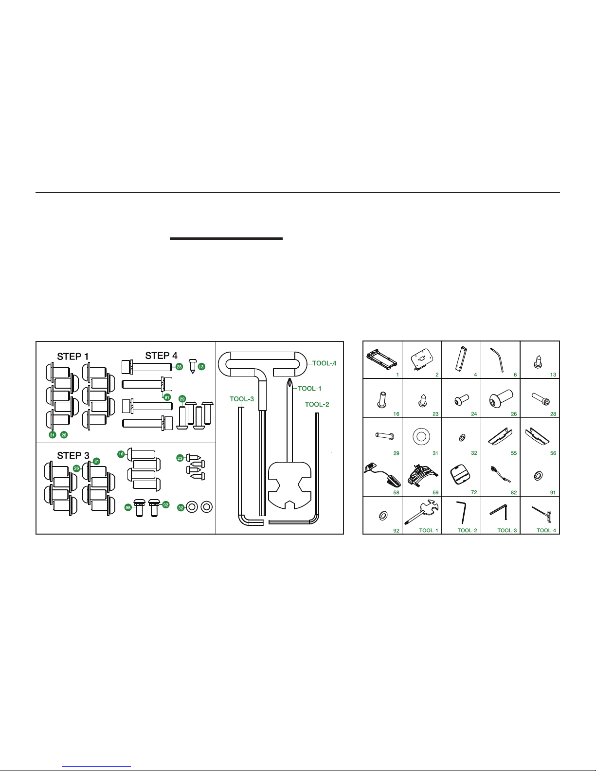
HARDWARE KIT
ASSEMBLY
Page 7
PAGE 7 PACEMASTER R20 SPORT TREADMILL USER MANUAL
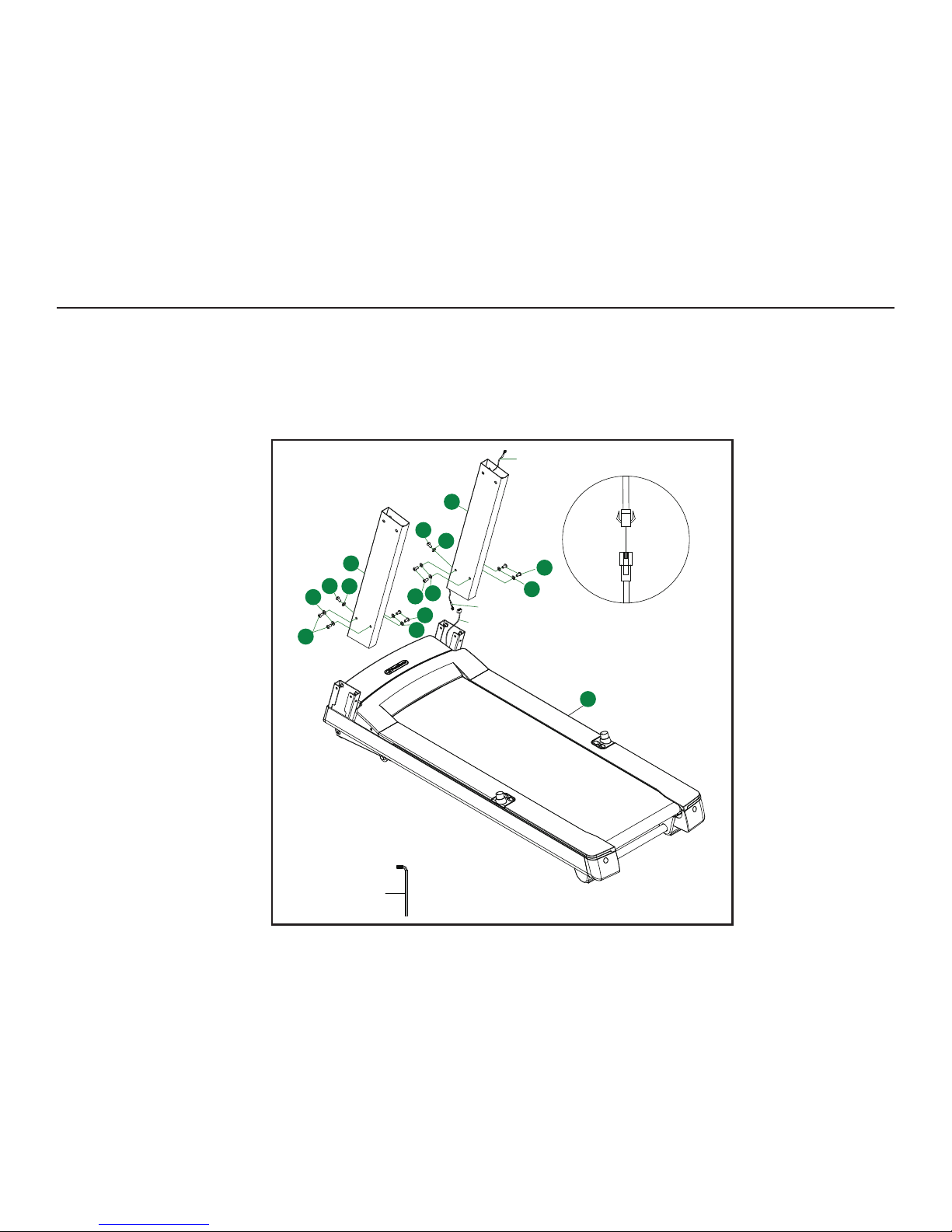
1. Route line A-1 through the upright columns (4) and expose
the connector.
2. Connect the wire A to A-1 as shown.
3. Insert the upright columns (4) into the main frame (1) and
secure it with the wrench TOOL-3; x with screw (26) and
washer (31), do not completely tighten these screws yet.
T00L-3
A-1
4
4
1
26
31
31
26
31
31
26
26
31
31
26
26
A-1
A
ASSEMBLY
STEP 1
Page 8
PAGE 8 PACEMASTER R20 SPORT TREADMILL USER MANUAL
A-2
A-1
59
4
4
ASSEMBLY
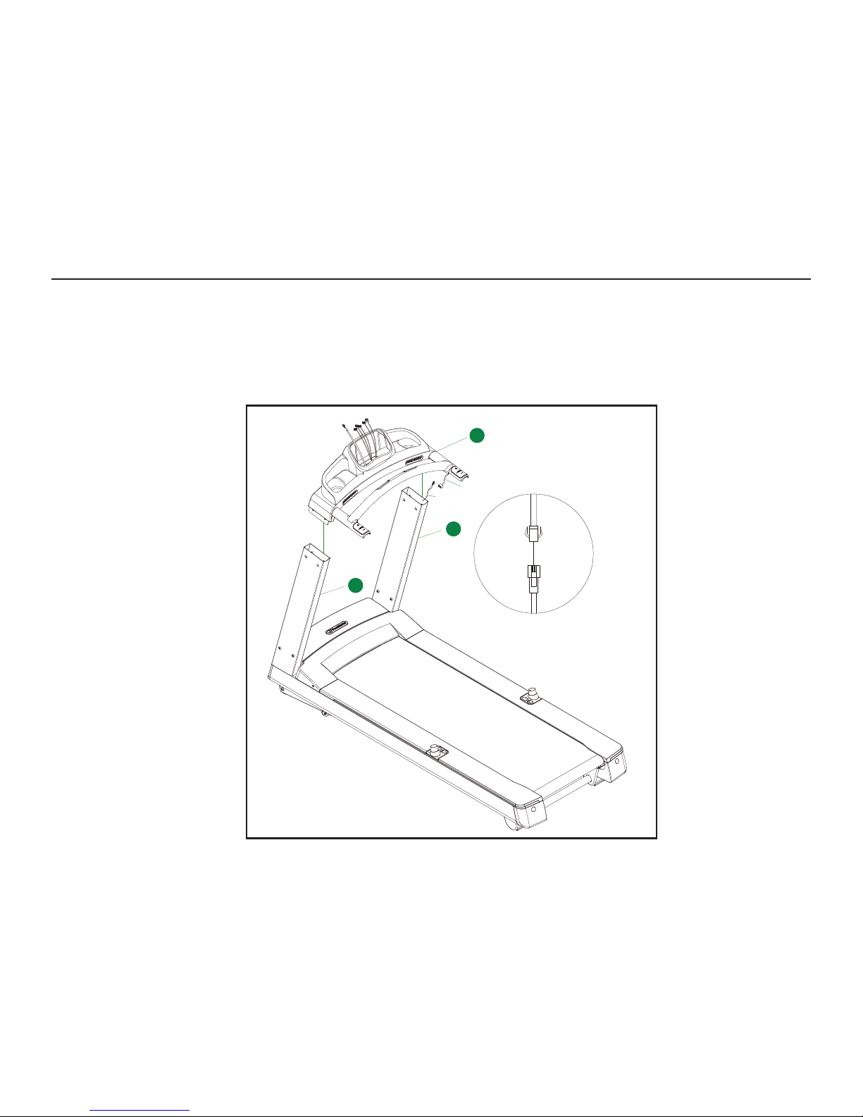
1. Connect wires A-1 and A-2 as shown.
2. Place the console (59) in the upright columns (4).
ASSEMBLY
STEP 2
Page 9
PAGE 9 PACEMASTER R20 SPORT TREADMILL USER MANUAL
T00L-2
T00L-3
26
26
26
26
31
31
31
31
23
16
16
6
6
32
92
98
32
92
98
55
T00L-1
59
1
4
4
23
56
STEP 3
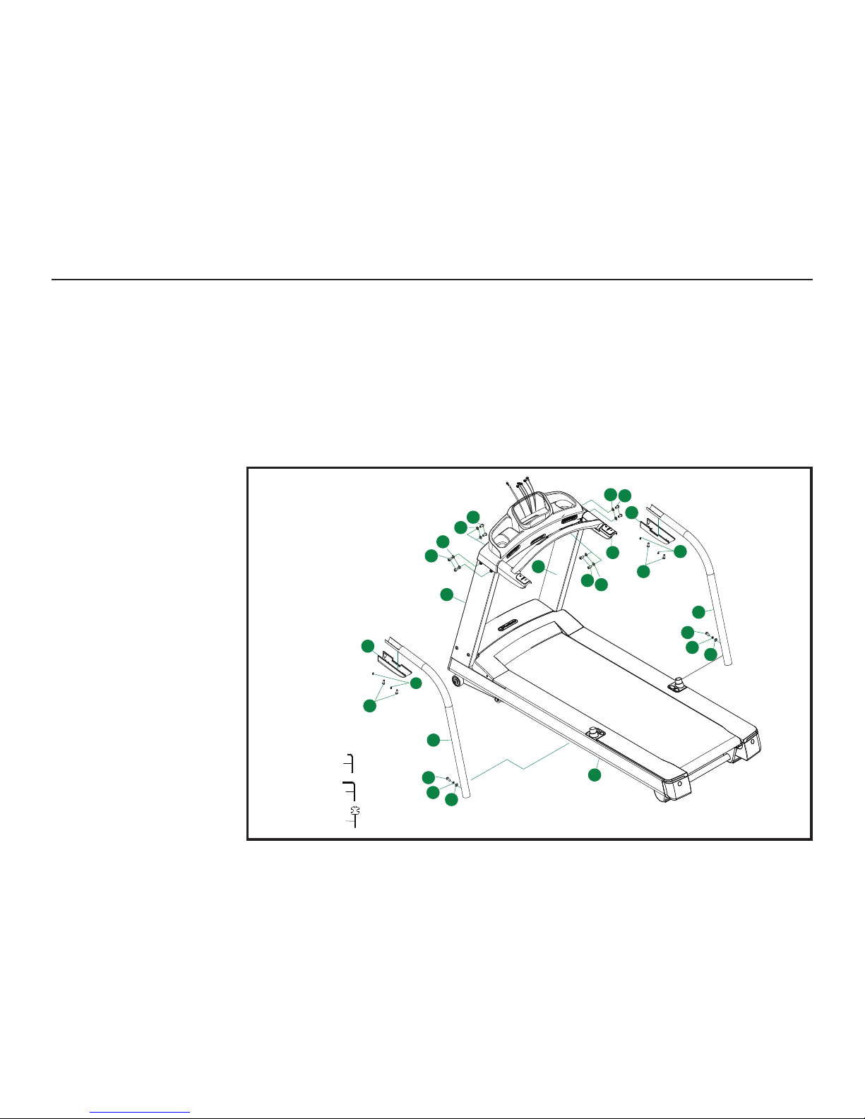
1. Match up the handrails (6) with the console (59) and main frame
(1) and use the hexagon socket head bolts (98) spring washer
(92) and curved washer (32) to secure the handrail (6) to the main
frame assembly (1) using wrench TOOL-2.
2. Use wrench TOOL-2 to t the hexagon socket head bolts
(16) to lock the left grip (55) onto the console (59).
3. Use the wrench TOOL-1 with Phillips pan head tapping screws (2 3)
to lock the left grip (55) into the console (59).
4. Use wrench TOOL-2 with hexagon socket head bolts (16)
to lock the right grip (56) into the console (59).
5. Use wrench TOOL-1 with Phillips pan head tapping screws (13) to
lock the right grip (56) into the console (59).
6. Use wrench TOOL-3 with hexagon socket head bolts (26) and at
washer (31) to lock the (59) into the upright columns.
7. Tighten all the above screws.
ASSEMBLY
Page 10
PAGE 10 PACEMASTER R20 SPORT TREADMILL USER MANUAL
72
A-2
A-3
B1
B2
C2
C1
28
91
T00L-3
59
D
29
13
A B C
D
72
2
T00L-1
2
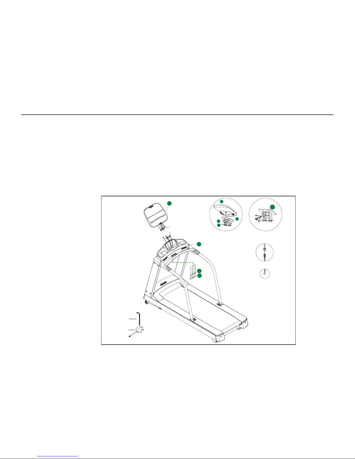
1. Insert the electronic cable line through the display device holder
(2) and secure the display device (72) with wrench TOOL-2 and
hexagon socket head bolts (29).
2. Secure the D wire to the display device holder (2) with
TOOL-1 and Phillips pan head tapping screws (13).
3. Connect A, B, and C wires as shown.
4. Use wrench TOOL-2 with hexagon socket head bolts (28) and a
spring washer (91) to secure the display device (72) to the console
(59).
5. Connect the fully assembled treadmill to power via an
appropriate outlet. The treadmill requires a connection to
a 3-pole grounded outlet connected to an (at minimum)
15-amp breaker. Consult a professional electrician to install
an appropriate outlet if none exists.
ASSEMBLY
STEP 4
Page 11
PAGE 11 PACEMASTER R20 SPORT TREADMILL USER MANUAL
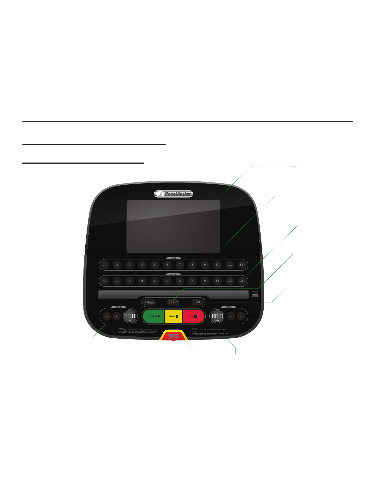
DISPLAY SCREEN
QUICKTAP
TM
SPEED BUTTONS
QUICKTAP
TM
INCLINE BUTTONS
BLUETOOTH® BUTTON
WITH INDICATOR LIGHT
INFORMATION BUTTON
FAN SWITCH BUTTON
WITH INDICATOR LIGHTS
INCLINE BUTTONS
SPEED BUTTONS
START, PAUSE, & STOP BUTTONSSAFETY KEY
CONSOLE OVERVIEW
TREADMILL OPERATION
AND ADJUSTMENTS
Page 12
PAGE 12 PACEMASTER R20 SPORT TREADMILL USER MANUAL
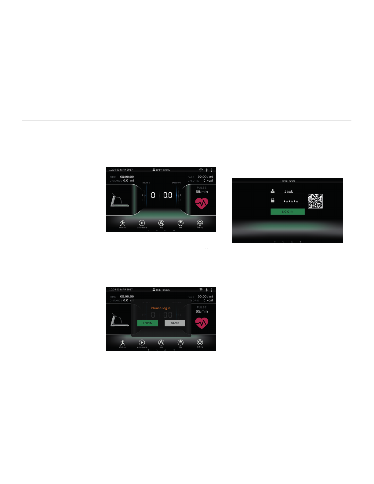
START SCREEN
Default starting screen is set up to allow for quick
workout start.
LOGIN / ACCOUNT CREATION
Login is optional. To log in, tap the “ME” button on the screen
and follow the prompts. Please create an account on Ruht
app. Then click“LOGIN” and enter your account and information and click “LOGIN”. You will then be logged in and the
screen will return to the Start Screen.
If you do not have an account, click “Create an
account” and follow the account creation prompts.
Account login is not required to use the treadmill.
However, in order to save your workout information login is
required.
BASIC WORKOUT CONSOLE OPERATIONS
• Press the “START” button: Treadmill ready to start, with a
sound prompt. The default start speed is
0.5 mph and the default start incline is 0.
• Press the “PAUSE” button to temporarily stop the treadmill. The Pause Screen will appear.
• If you press the “START” when the treadmill is paused the
treadmill will reset to 0 speed and incline.
• Use the “QUICKTAP
TM
INCLINE” and “QUICKTAPTM SPEED”
buttons on the console to quickly select specic workout
levels.
TREADMILL OPERATION AND ADJUSTMENTS
SCREEN OVERVIEW
Page 13
PAGE 13 PACEMASTER R20 SPORT TREADMILL USER MANUAL
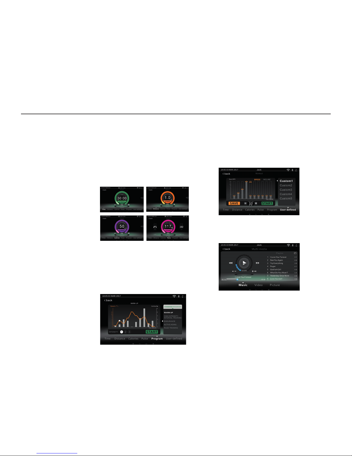
ADJUSTING WORKOUT LEVELS
You can adjust your workout to the precise level and
intensity you desire:
First, select the “WORKOUT” button on the screen. Then
toggle through the “ TIME”, “DISTANCE”, “CALORIES”,
and other options to adjust your specic workout levels.
Adjust the custom levels by either pressing “+” and “-”
or by sliding the color band with your nger.
When you’ve entered your customized workout goals,
press “START” to begin your workout.
PREPROGRAMMED WORKOUTS
To select a preprogrammed workout, select “WORKOUT”
on the screen, then select “PROGRAM”. You’ll then be
able to see the dierent program levels: rst, select the
workout category you’d like to use. Then you will see the
specic workout levels (they vary in intensity and settings).
After you’ve selected a preprogrammed workout, press
the “START” button to begin your workout.
USER-DEFINED PROGRAM
When you are logged into an account you can save
workouts and quickly select saved workouts. To find
a saved workout, select the “USER-DEFINED” button
inside Workout, then you will see the workouts that
are saved to your account. To save a workout,
press the “SAVE” button to record your current
speed and incline.
ENTERTAINMENT AND MEDIA
Press the “MULTIMEDIA” button to select between the
“Music”, “Video”, and “Picture” func tions.
HEART-RATE MONITORING
To use the Heart Rate Monitors, grip the pulse
sensors on both handrails. Your pulse rate will display
on the screen after several seconds.
TREADMILL OPERATION AND ADJUSTMENTS
Page 14
PAGE 14 PACEMASTER R20 SPORT TREADMILL USER MANUAL
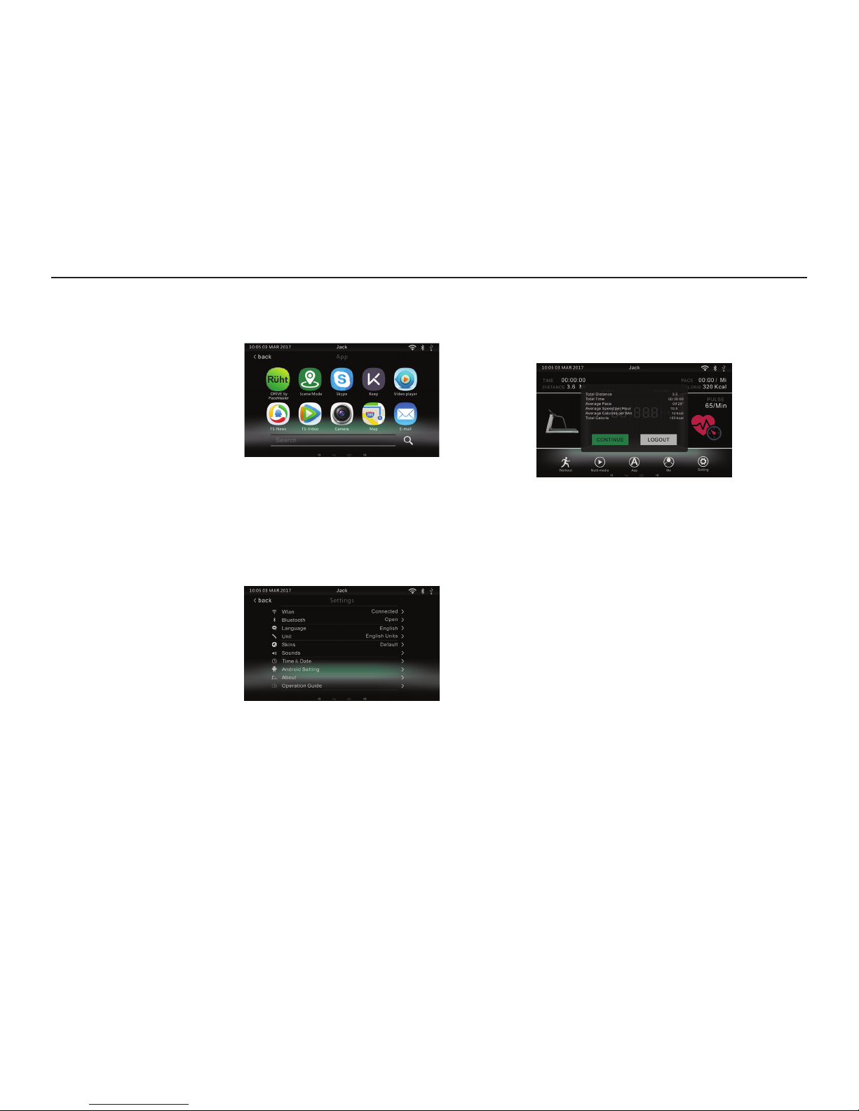
APP
Press the “APP” button to connect to your App. You will
need access to Wi-Fi in order to connect to the App.
SETTINGS
Press the “SET TINGS” button to enter the settings interface. Here you’ll be able to set and adjust the Wi-Fi,
Bluetooth®, language mode, units of measurement,
UI skin, sound, and other system settings. You’ll also have access to the document management and Android
settings; however, adjusting any Android settings is not
recommended.
WORKOUT DATA
When the treadmill is in a standby status, tap the
“ME” icon to access workout data.
TREADMILL OPERATION AND ADJUSTMENTS
Page 15
PAGE 15 PACEMASTER R20 SPORT TREADMILL USER MANUAL
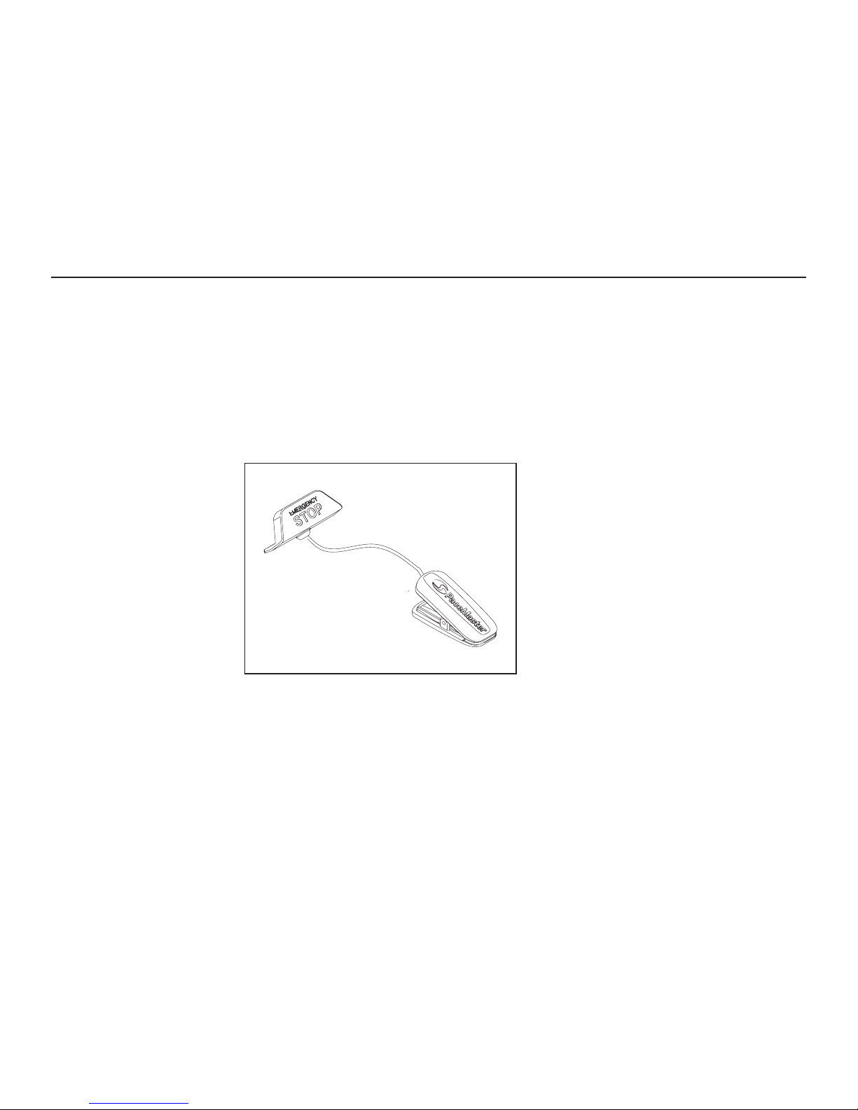
HOW TO USE THE SAFETY KEY AND TEST THE EMERGENCY STOP
1. Adjust the length of the Safety Key cord. It should be
long enough that when it is inserted into the console
and clipped onto your clothes you can correctly use
the treadmill without dislodging the Safety Key.
2. Attach the clip to a convenient area on your clothing
such as a waistband or shirt hem. Insert the key into
the correct area on the treadmill’s console.
3. IMPORTANT: Test the clip by carefully taking a few
steps backward; if the key does not pull out of the
console for an emergency stop adjust the position
of the clip or the length of the cord. The Safety Key
must be correctly adjusted in order to work correctly
in an emergency situation.
4. Always use the Safety Key correctly during
treadmill workouts.
TREADMILL OPERATION AND ADJUSTMENTS
USING THE SAFETY KEY
Page 16
PAGE 16 PACEMASTER R20 SPORT TREADMILL USER MANUALTREADMILL OPERATION AND ADJUSTMENTS
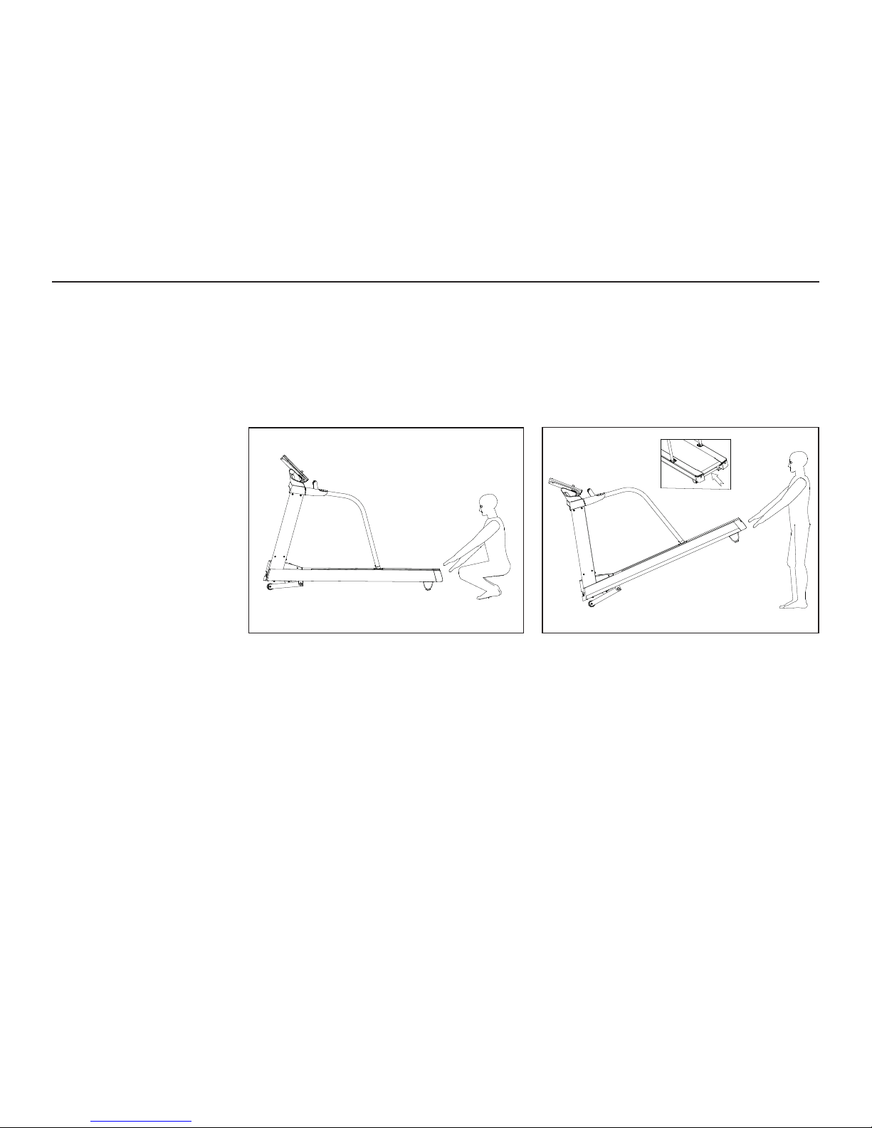
CAUTION Use extreme caution while moving the
treadmill to avoid injury.
1. Unplug power cord. Grip the treadmill underneath
the back end by the cross-bar; carefully raise the
treadmill’s back end.
2. When the treadmill is tilted up enough to be
weighted entirely on the front transport wheels,
carefully move the treadmill.
3. When situated, carefully lower the treadmill.
MOVING THE TREADMILL
Page 17

PAGE 17 PACEMASTER R20 SPORT TREADMILL USER MANUAL
The heart rate monitor is specially designed for accuracy,
comfort, and durability. To get the best performance from
the heart rate monitor, please read the instructions below.
HOW TO PUT ON THE HEART RATE MONITOR
The heart rate monitor consists of two components: the
chest strap and the transmitter. Follow the steps below
to put on the heart rate monitor.
1. Insert the tab on one end of the chest strap through
one end of the transmitter and attach it.
2. Wrap the heart rate monitor around your chest and
attach the other end of the chest strap to the
transmitter. If necessary adjust the length of the chest
strap. The heart rate monitor should be under your
clothing, against your skin, and as high under the
pectoral muscles or breasts as is comfortable.
3. Pull the transmitter away from your body a few inches
and locate the two electrode areas on the inner side.
Wet both electrode areas. Return the transmitter to a
position against your chest.
USING THE HEART RATE MONITOR
1. Make sure that the heart rate monitor is under your
clothing, against your skin, and as high under the
pectoral muscles or breasts as is comfortable.
Note: If the heart rate monitor does not function
when positioned as described, try moving it slightly
lower or higher on your chest.
2. Moisten the two electrode areas on the transmitter with
saline solution. If heart rate readings do not appear until
you begin perspiring, re-wet the electrode areas.
3. For the console to display heart rate readings, the
user must be within arm’s length of the console.
4. The heart rate monitor is designed to work with
people who have normal heart rhythms. Heart rate
reading problems may be caused by medical conditions such as premature ventricular contractions
(pvcs), tachycardia bursts, and arrhythmia.
5. The operation of the heart rate monitor can be aected
by magnetic interference caused by high power lines
or other sources. If it is suspected that magnetic
interference may be causing a problem, try relocating
the treadmill.
6. If the heart rate monitor still does not function
properly, test it by having another person try it.
7. The battery may need to be replaced.
HEART RATE MONITOR CARE AND MAINTENANCE
• Thoroughly clean and dry the heart rate monitor
after each use. The heart rate monitor is activated
when the electrode areas are wetted and the heart
rate monitor is put on; the heart rate monitor shuts
o when it is removed and the electrode areas are
dried. If the heart rate monitor is not dried after each
use, it may remain activated longer than necessary.
• Store the heart rate monitor in a warm, dry place. Do
not store the heart rate monitor in a plastic bag or
other container that may trap moisture.
• Do not expose the heart rate monitor to direct
sunlight for extended periods of time. Do not expose
the heart rate monitor to temperatures above 122º
Fahrenheit (50º Celsius) or below 14º Fahrenheit
(-10º Celsius).
• Do not excessively bend or stretch the transmitter
when using or storing the heart rate monitor.
• Clean the transmitter using water and mild soap.
Never use alcohol, abrasives, or chemicals. The
chest strap may be hand washed and air dried.
HEART RATE
MONITOR
WARNING:
Do not use the heart
rate monitor if you
have an implanted
medical device
such as a pacemaker:
be sure to check with
your physician prior
to using the heart rate
monitor if you have
an implanted
medical device such
as a pacemaker.
!
Page 18

PAGE 18 PACEMASTER R20 SPORT TREADMILL USER MANUAL
BELT CARE AND LUBRICATION
You must lubricate your treadmill belt annually (or more often if your treadmill is
heavily used) in order to keep vital treadmill parts including the deck, belt, motor,
and motor controller from prematurely wearing out. Annual lubrication is required to
maintain the product warranty. Lubricating your treadmill can also help it run more
quietly and reduce friction between the belt and the treadmill deck.
HOW TO ASSESS YOUR TREADMILL’S BELT
The area between the running deck and the running
belt has been pre-lubricated. Excessive friction can
seriously decrease the treadmill’s performance, so
regular assessment and lucubration is essential:
check the treadmill’s lubrication levels regularly.
1. Unplug the power cord.
2. Inspect belt and deck by placing your hand between
the belt and deck. The deck should be smooth. The
belt should have a consistent feel from side to side
(a belt can be worn out without any sensory signs
of a problem). If you feel deep grooves in the deck
or uneven wear on the underside of the belt, part
replacement is necessary. Continued use of your
treadmill may damage the treadmill.
3. If your treadmill has an excessive accumulation of
dirt and contaminants you must clean them out. If
these are trapped during the belt lubrication process,
signicant damage will occur. Do NOT apply
lubricant if there are contaminants under the belt.
Contact a Certied Service Provider for service if
contaminant removal is necessary.
LUBRICATION SCHEDULE
• Light Use: Apply lubricant once a year
(Treadmill is used less than 3 hours per week)
• Regular Use: Apply lubricant every 6 months
(Treadmill used up to 5 hours per week)
• Heavy Use: Apply lubricant every 3 months
(Treadmill used more than 5 hours per week)
LUBRICATING YOUR TREADMILL
1. Lift the running belt and inject 0.5 oz. of treadmill
lubricant across the running board. Do not put any
lubricant on any surface with which your feet make
contact. The lubricant will spread evenly in the next
step. Do not apply or spread the lubricant by hand.
2. Run the treadmill at the speed of 2 mph for 3 minutes
to fully permeate the lubricant (every treadmill has a
bottle of lubricant).
MAINTENANCE
Page 19

PAGE 19 PACEMASTER R20 SPORT TREADMILL USER MANUAL
3. Using your treadmill’s handrails and safety switch for
safety and support, walk on the treadmill at 2-3 mph.
CAUTION: BELT MAY HESITATE. THIS CAN CAUSE
INJURY IF BELT IS NOT PROPERLY TENSIONED.
Within 5 minutes the lubricant will be preliminarily
walked into the backing of the belt. Damage and/or
injury may occur if the belt is not properly centered
and tensioned (refer to the Troubleshooting section
of the user manual if needed).
CAUTION: Do not run on the treadmill until you are
certain the belt tension and centering is correct
according to your owner’s manual specifications.
Make certain that there are no friction spots that may
cause belt hesitation. Injury can occur if belt is not
adjusted properly.
HOW TO CLEAN THE TREADMILL
1. Always unplug the treadmill before cleaning it.
2. Dust out the treadmill regularly and keep all parts
clean. Clean both sides of the belt to avoid dust
accumulation under the belt. If needed, use a damp
soapy cloth to gently wipe the surface. Don’t splash
water onto any part of the treadmill.
3. If there is excessive dirt under the running belt or
inside the treadmill contact a Certied Service
Provider for service or assistance.
MAINTENANCE
Page 20
PAGE 20 PACEMASTER R20 SPORT TREADMILL USER MANUAL
SYMPTOMS AND SOLUTIONS
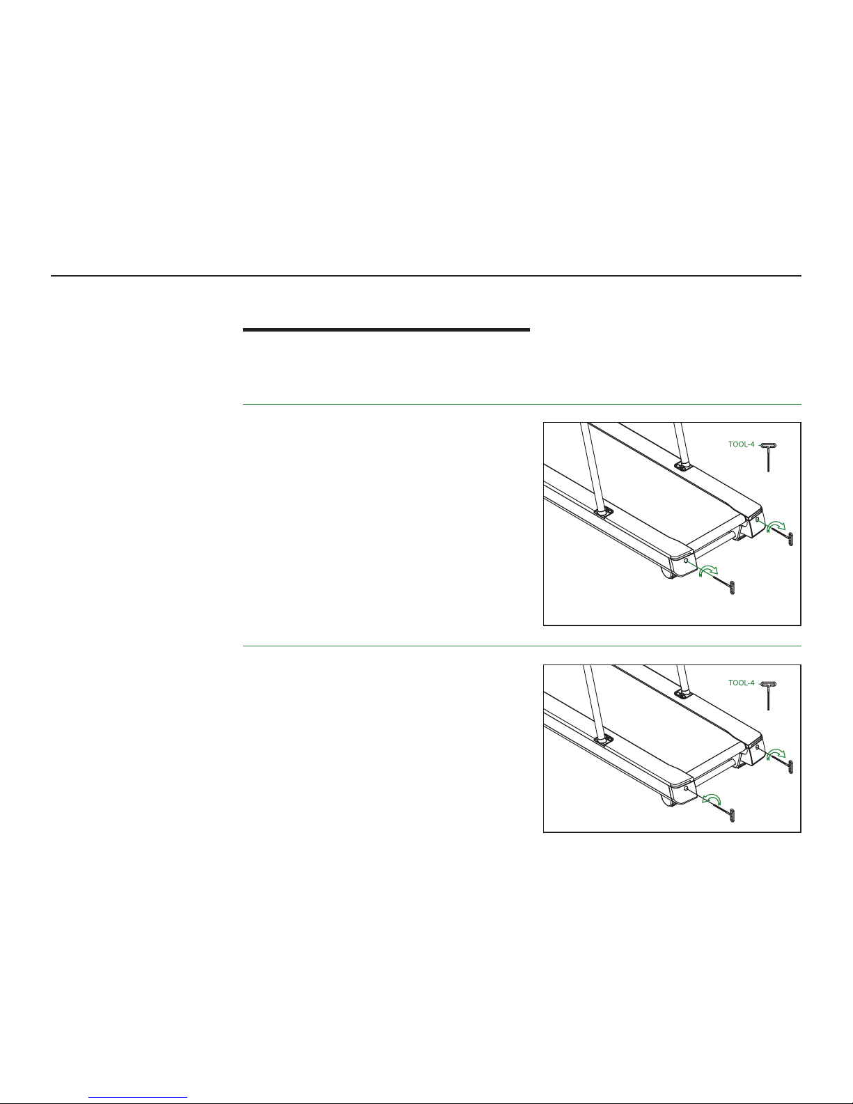
Most treadmill problems can be resolved quickly using the following steps. If there
is a problem that you cannot easily solve, contact our Customer Service Team.
A. SYMPTOM
Sudden changes in speed while using the treadmill.
SOLUTION
The running belt can become slack from use, causing
the belt to slip. Adjust belt tension right away:
1. Press the STOP button.
2. Unplug the power cord.
3. You can tell if the belt is too loose or tight by gently
lifting the belt away from the platform. There should be
between 2-3 inches of space.
3. If the belt is too loose adjust the belt. Use a socket head
wrench to adjust the rear roller adjustment bolts, turning
each bolt clockwise ¼ turn. If necessary, repeat by ¼
turns until the running belt has correct belt tension.
B. SYMPTOM
The distance between the running belt and the sides of
the platform is uneven.
SOLUTION
1. Run the treadmill while you stand behind it.
2. If the running belt deviates to the left, turn the left hexagon
socket head bolt (11) clockwise ½ turn. If the running belt
deviates to the right, turn the right hexagon socket head
bolt (11) clockwise ½ turn.
3. Adjust as needed to center the belt, but be careful not to
cause excess tension on the running belt.
TROUBLESHOOTING
Page 21

PAGE 21 PACEMASTER R20 SPORT TREADMILL USER MANUAL
C. SYMPTOM
Treadmill will not power on.
SOLUTION
1. Verify that the power cord is plugged into a functional power outlet.
2. Make sure the power switch is set to ON. To reset the power, turn the
power switch o, wait ve minutes, and turn the switch back on.
3. Check that the Safety Key is correctly inserted into the console.
D. SYMPTOM
Sudden power loss while running.
SOLUTION
1. Check the power switch. (See Symptom C above.) To reset, set the power
switch in the o position, wait ve minutes, and switch it back on.
2. Verify that the power cord is plugged into a functional power outlet. If the
power supply has been connected, power o, wait ve minutes, and switch
it back on.
3. Pull the safety clip/safety switch, and plug it back in again.
If you are unable to clear any symptoms or are in need of additional
assistance, please contact our Customer Service Team.
TROUBLESHOOTING
Page 22

PAGE 22 PACEMASTER R20 SPORT TREADMILL USER MANUAL
PARTS LIST
No Part Na me Specifi cations Part Numb er Qty
1
Ma
in Frame Asse mbly
20
70101060024
1
2
Di
splay Devic e Holder
20
70101030561
1
3
Frame Assem bly 2070101030563 1
4
Up
right Col umns
20
7019203003 3
2
5
Sq
uare Tube Plug
50 X 5
0 X 3
10
31030000 533
4
6
Handrail 2070192030032 2
7
Ba
se Assemb ly
20
70101030560
1
8
St
rengthening Tube
20
70192030027
1
9
He
x Bolts
1/
2-13 X 95 X 25mm
10
32010100202
2
10
Lo
cknut
1/
2-13 (Thin)
10
320404 00079
2
11
He
xagon Soc ket Head Bolts
M1
0 X 58mm
10
32010200179
3
12
He
xagon Soc ket Head Bolts
M1
0 X 40 X 20mm
10
32010200231
1
13
Phi
llips Pan Head Tapping Screws
St
4.2 X 12mm
10
320506 00023
35
14
Phi
llips Pan Head Tapping Screws
10
611; M4.0-0.7 X 10mm
10
320306 00034
16
15
Ph
illips Pan He ad Flange Face Tapping S crew Type F Type
St
2.6 X 8.0mm
10
320506 00126
12
1
6
He
xagon Soc ket Head Bolts
M8 X 2
5mm
10
3201020007 2
8
17
Lo
cknut
M8 X (
7.6⁓8.0mm)
10
320404 00018
4
18
Phi
llips Pan Head Tapping Screws
M3
.0-0.5 X 2 5mm
10
320306 00090
1
19
Philli
ps Countersunk Head Screws
M3 X 1
0mm
10
320303 00055
2
20
L
ocknut
M3
-0.5
10
320404 00090
16
2
1
He
xagon Coun tersunk Head Screws
M1
0 X 35mm
10
32010300014
2
22
He
xagon Soc ket Head Bolts
M6 X
12mm; Electrophoresis
10
32010 20015 9
8
23
Philli
ps Pan Head Tapping Screws
St
4.2 X 16mm
10
320506 00024
12
2
4
He
xagon Soc ket Head Bolts
M6 X 1
0mm
10
3203020 0002
8
25
He
xagon Soc ket Head Bolts
M6 X 1
6mm
10
320102000 22
4
26
He
xagon Soc ket Head Bolts
M1
0 X 20mm
10
32010200116
18
2
7
He
xagon Soc ket Head Bolts
M3 X 1
0mm
10
32010600 024
12
2
8
He
xagon Soc ket Head Bolts
M8 X 4
5mm
10
320102003 40
4
29
He
xagon Soc ket Head Bolts
M6 X 2
0mm
10
320102000 05
4
30
FlatWashers
⁓13X⁓32X1
.5mm 1032070100150 4
31 FlatWashers
⁓1
0.4
X⁓20X1
.0 103207010005 3 24
32
Cu
rved Washe rs
⁓
8.5 X ⁓19.0 X ⁓1.5 X R25.4
1
032079900068
2
33
Ru
nning Boar d
14
20 X 680 X 19.05; Rohs
10
39990 000837
1
34
Fr
ont Roller A ssembly
2.5” 10
340200 00087
1
35
Re
ar Drum Asse mbly
2.5” 10
340200 00088
1
36
Casing
⁓2
1.8
X⁓1
3.1
X3
6.8 1032090100132 4
37 Sleeves
10
31060000035
8
38
Roller
⁓7
6.2
X3
0.5 103199000022 5B 4
39 V-Belt
8P
j525
10
340700 00052
1
40
Pu
lse Sensor S heet Left 1
⁓0.3 10
35050000185
1
4
1
Pu
lse Sensor S heet Left 2
⁓0.3 10
35050000186
1
4
2
Pu
lse Sensor S heet Right 1
⁓0.3 10
35050000187
1
4
3
Pu
lse Sensor S heet Right 2
⁓0.3 10
35050000188
1
4
4 EvaPad
⁓48X0
.8mm 1031990001022 4
45
Cu
shion
10
31990000 944
4
46
In
strument N ameplate Logo
10
39990 000820
1
47
Trea
dmill Nameplate Logo
10
39990000821
1
48
Sw
itch Rope
10
350200 00785
1
49
Ru
bber Mat
77 X 4
5 X 43
10
31990000 971
2
50
Sa
fety Switc h
10
31010000564
1
51
Fa
n Middle Co ver
12
6.5 X 34.5 X 17.1
10
31010000566
1
52
Fa
n Left Cover
12
4.3 X 32 X 20.5
10
31010000567
1
53
Fa
n Right Cover
12
3.6 X 32.20. 5
10
31010000568
1
No Part Na me Specifi cations Part Numb er Qty
54
Pu
lse Plate
31
8.6 X 56.2 X 31.3
10
31010000570
1
55
Le
ft Grip
24
8.2 X 58.7 X 56. 2
10
31010000571
1
56
Right Gri p 248.2 X 58.7 X 56 .2 1031010000 572 1
57
Re
ar Foot L
13
0.9 X 145.2 X 145.1
10
31010000573
2
58
Sa
fety Clip
61
.8 X 25.1 X 29
10
31010000586
1
59
Consol e Top C over 711.1 X 143.3 X 2 21.7 2070193050120 1
60
Co
nsole Bot tom Cover
69
5.5 X 73.5 X 184.4
20
70193050122
1
61
Co
nsole Mid dle Cover
79
9.6 X 193.3 X 115.1
20
70193030118
1
62
Pu
lse Handl e Cover
78
2 X 248.4 X 116.9
20
70193030127
1
63
Mo
tor Cover
78
6.4 X 400.7 X 170.2
20
70193050123
1
64
Mo
tor Front Cover
78
7.4 X 127.3 X 8 3.8
20
70193030119
1
65
Le
ft Panel
15
31.5 X 140.5 X 46.3
20
70193030120
1
66
Ri
ght Panel
15
31.5 X 140.5 X 46.3
20
70193030121
1
67
Fa
n Suppor t Frame 1
⁓2 20
7019103 0163
1
6
8
Fa
n Suppor t Frame 2
⁓2 20
7019103 0164
1
69
Fa
n Suppor t Frame 3
⁓2 20
7019103 0167
1
7
0
Su
pport Ba se
⁓3 20
7019103 0166
1
71
LargeGasket
⁓3
2 10 36010001768 2
72
Di
splay Devic e
42
8 X 379 X 61
10
35030 000244
1
72
A
To
uch Panel
El
ectroni c Watch Parts
1
72
B
Pr
essure Plat e
E l
ectroni c Watch Parts
1
72
C
Ip
ad Shelf
El
ectroni c Watch Parts
1
72
D
Sa
fety Switc h Seat
El
ectroni c Watch Parts
1
72
E
Sp
eaker
El
ectroni c Watch Parts
2
72
F
El
ectroni c Cable Under Cover
El
ectroni c Watch Parts
1
73
Co
ntrol Panel
10
35030 000240
1
74
Fan 10
35990 000311
3
75
Fr
equency C onverter
10
35030 000235
1
76
M
otor
10
35010000192
1
77
Li
ft Motor
10
35010000191
1
78
F
ilter
10
35030 000236
1
79
I
nductan ce
10
350500 00190
1
80
Ai
r Switch
10
35060000074
1
81
Po
wer Outlet
10
35990 000285
1
82
Po
wer Cable
10
350200 00782
1
83
RunningBelt 508
X3
225
XΔ
2.3mm 1034990 000165B 1
84
He
xagon Coun tersunk Head Screws
M1
0 X 25mm
10
320303 00042
4
85
Lo
cknut
M1
0 X (9.7⁓10.1mm)
10 3
204 040 0011
12
8
6
Pu
lse Handl e Under The Bar
77
1.8 X 72 X 113.4
20
701990300 37
1
87
Ba
ck Cover L
15
7.8 X 106.2 X 127.9
20
701990300 38
1
88
Ba
ck Cover R
15
7.8 X 106.2 X 127.9
20
701990300 39
1
89
Re
ar Seat L
20
701990300 40
1
90
Re
ar Seat R
20
701990300 41
1
91
SpringWasher
⁓8 1
089901030 284
92 Sprin gWasher
⁓6 1
089901030 272
93
Cl
amps
17
.3 X 11 X 3.7 T=0.6
10
329900 00062
4
94
FlatWasher
⁓1
0.4
x⁓32x1
.8mm 103207010003 7 4
95
Ph
illips Pan He ad Flanged Tapping Scre ws F Typ e #8
32 x 1
2.7mm
10
320506 00073
5
96
He
xagon Soc ket Pan Head Bolts
M1
0 x 60 x 15mm
10
320102000 96
1
97
Ev
a Pad
70 x 4
5 x 3.0mm
10
31990001021
4
98
Hex
agon Socket Head Bolts
M6 x 1
5mm
2
TO
OLS: TOOL-1 Wrench, TOOL-2 Wren ch, TOOL-3 Wrench, and Tool-4 Wr ench
Page 23
PACEMASTER R20 SPORT TREADMILL USER MANUALPAGE 23
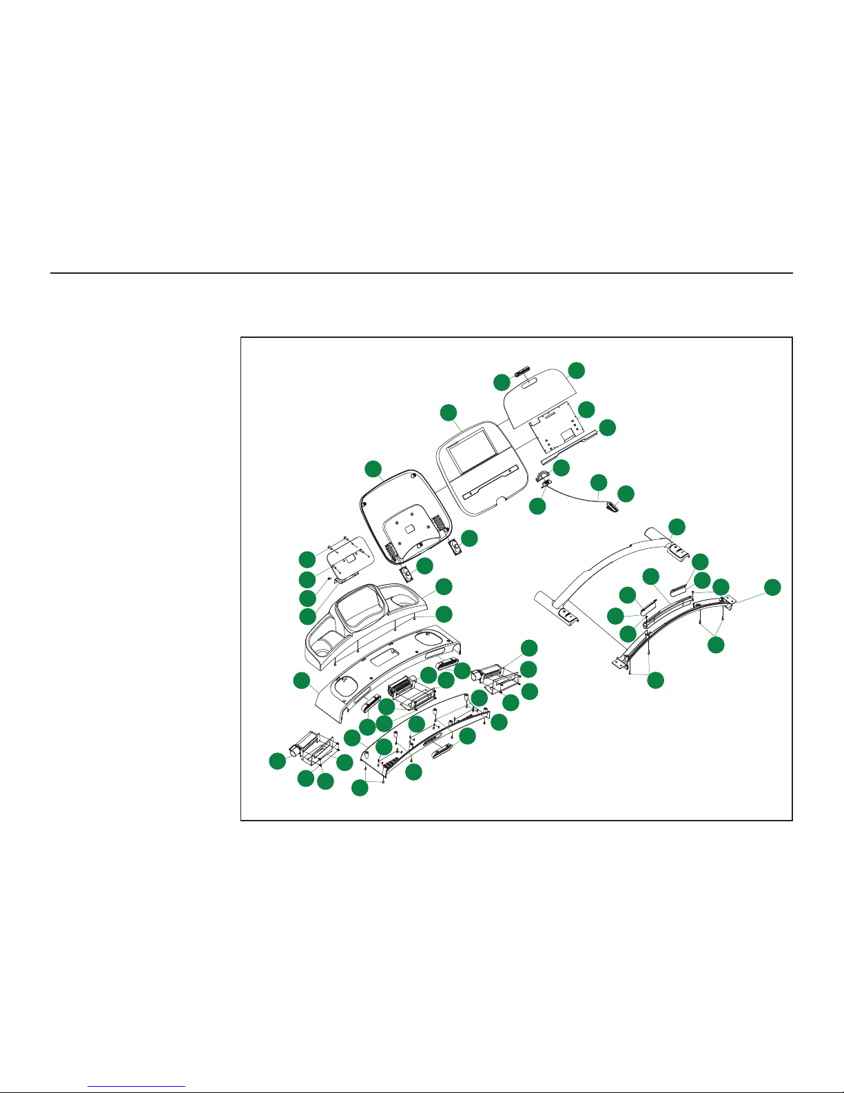
EXPLODED DIAGRAMS
72
48
58
46
72A
72B
72C
72D
72F
72E
72E
27
29
29
2
40
41
42
43
51
52
53
54
59
61
60
62
67
69
68
74
74
74
86
13
13
13
13
13
13
13
13
15
15
15
20
20
27
27
20
13
50
DIAGRAM A
Page 24
PAGE 24 PACEMASTER R20 SPORT TREADMILL USER MANUAL
3
4
6
6
26
26
26
26
26
26
26
26
16
16
28
31
13
31
31
4
31
31
31
31
32
32
55
56
91
92
98
92
98
13
13
13
13
26
26
31
31
24
24
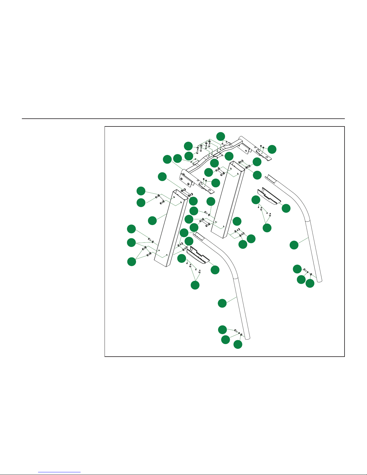
DIAGRAM B
EXPLODED DIAGRAMS
Page 25
PAGE 25 PACEMASTER R20 SPORT TREADMILL USER MANUAL
1
7
8
9
9
10
36
10
11
11
11
12
23
23
14
14
14
14
16
17
18
19
20
21
95
95
14
14
22
22
23
23
23
23
25
25
24
30
36
30
30
33
34
35
39
45
45
45
45
47
49
49
57
57
63
64
65
66
70
71
71
73
75
76
77
78
79
80
81
82
83
84
84
85
85
87
88
89
90
93
93
13
13
13
13
13
13
31
94
38
38
38
37
37
37
37
94
94
97
97
85
85
85
85
85
85
5
5
31
5
5
95
14
96
44
44
44
44
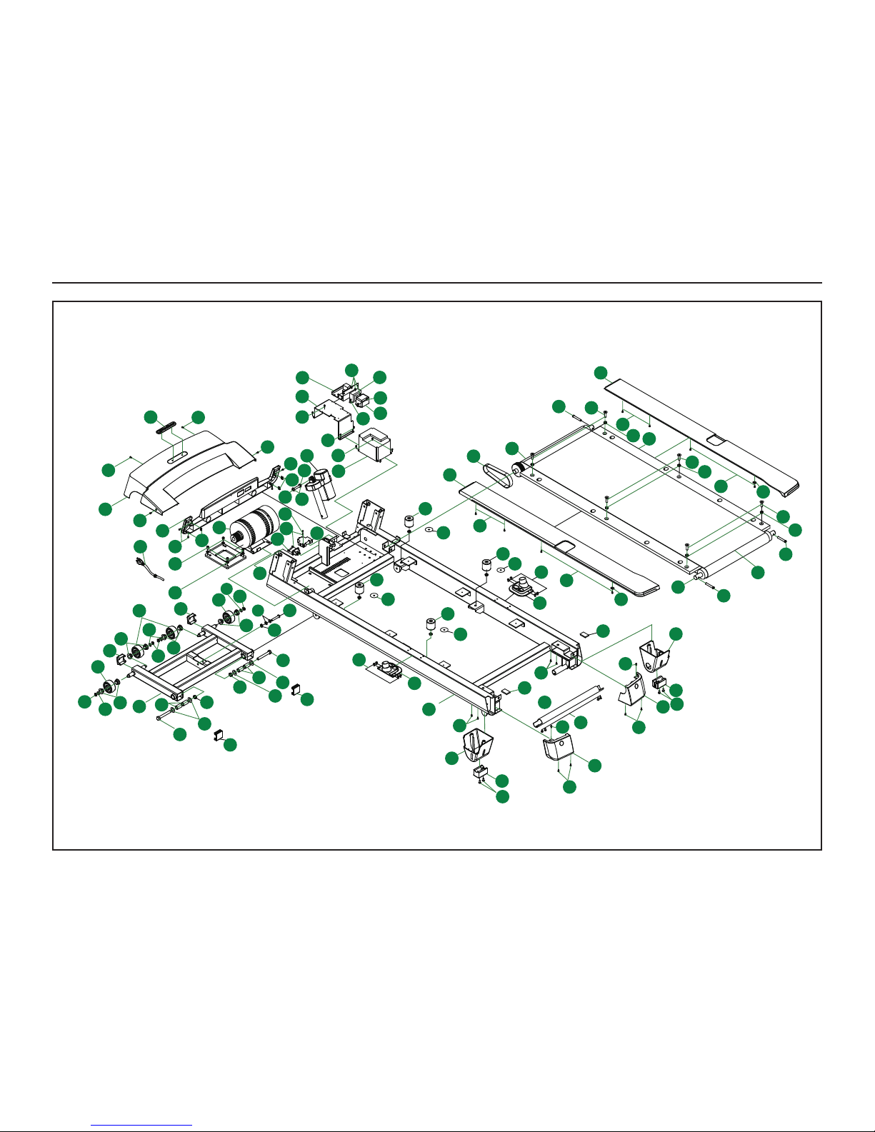
EXPLODED DIAGRAMS
DIAGRAM C
Page 26

PAGE 26 PACEMASTER R20 SPORT TREADMILL USER MANUAL
WARRANTY
INFORMATION
Register your product today. PaceMaster backs your treadmill with the warranty provided below. For
PaceMaster to respond to any problems you may have, we need your warranty information on file.
PaceMaster will send you a complimentary gift upon receiving your product warranty registration.
OUR WARRANTY
This PaceMaster exercise equipment (“Product”) is warranted to be free
of defects in material and workmanship under normal use and service
conditions. The frame, drive motor, and walking platform are warranted
for the lifetime of the Product.
For Residential use (in-home only), Non-wearable Parts and
electronics are warranted for five (5) years from the date of purchase.
Wearable parts (drive belt, walking belt, grips, overlays, plastic parts)
and Labor is warranted for one (1) year from the date of purchase.
For Semi-commercial [paying facilities or up to five (5) hours of use
per day], Non-wearable Parts and electronics are warranted for one (1)
year from the date of purchase. Wearable parts (drive belt, walking belt,
grips, overlays, plastic parts) are warranted for six (6) months and Labor
is warranted for one (1) year from the date of purchase.
PaceMaster does not offer a Commercial use [paying facilities and/
or five (5) or more hours of use per day] warranty for this product.
WHO IS COVERED
PaceMaster will repair or replace the Product for the original purchaser
or the original recipient if the product is a gift.
HOW LONG IS IT COVERED
All coverage is provided by specific Product according to the matrix
listed on the following page:
www.pacemaster.com/warranty-matrix
WHO PAYS TRANSPORTATION, INSURANCE, AND IN-HOME SERVICE
If the Product requires return to a service facility for repairs, PaceMaster will pay all transportation and insurance charges for the first year.
After the first year, you are responsible for transportation and insurance
charges. For in-home service, you may be responsible for a minimal trip
charge.
WHAT WE WILL DO TO CORRECT COVERED DEFECTS
We will repair or replace the Product, at PaceMaster’s option. In most
cases, replacement parts will be provided to the owner. In the event
more extensive repairs are required, the Product will be shipped to
a designated repair facility. Replacement parts are warranted for the
remaining portion of the original warranty period.
WHAT IS NOT COVERED
Any failures or damage caused by unauthorized service, misuse,
accident, negligence, improper assembly or installation, debris resulting
from any construction activities in the Product’s environment, rust or
corrosion as a result of the Product’s location, alterations, or modifications
without our written authorization or by failure on your part to use,
operate, and maintain the Product as set out in your User Manual.
All terms of this warranty are void if this product is moved beyond the
continental borders of the United States of America (excluding Alaska,
Hawaii, and Canada) and are then subject to the terms provided by that
country’s local authorized PaceMaster representative.
WHAT YOU MUST DO
Retain proof of purchase. Always use, operate, and maintain the
Product as specified in the User Manual. Notify PaceMaster Customer
Service of any defect within 10 days after discovery of the defect. If requested, return any defective part for replacement or the entire Product
for repair. Your treadmill requires periodic maintenance specified in the
User Manual, including annual application of lubricant to the belt, or the
warranty is voided. Use of the treadmill must comply with directions in
the User Manual or the warranty is voided.
For warranty service, please contact PaceMaster’s Customer Service
Team. Be prepared to offer the model number and serial number of the
product.
EXCLUSIVE WARRANTY
THIS LIMITED WARRANTY IS IN LIEU OF ALL OTHER WARRANTIES,
implied or expressed. PaceMaster specifically disclaims any other
implied warranties of merchantability and fitness for a particular
purpose. PaceMaster is not responsible or liable for indirect, special, or
consequential damages arising out of or in connection with the use or
performance of this Product. Some states do not allow the exclusion or
limitation of implied warranties or of liability for incidental or consequential damages, so the above limitations or exclusions may not apply
to you. This warranty provides you certain rights. You may have other
rights, which vary from state to state.
PACEMASTER GUARANTEE
Our Products are designed and manufactured to the highest standards.
We want you completely satisfied with our Products and will do everything possible under the terms of this warranty to keep you secure in
knowing you have bought the best.
For questions regarding the use and maintenance of your product,
please contact our PaceMaster Customer Service Team:
PaceMaster.com/help
Phone: (888) 699-8918
Email: [email protected]
Mail: PO Box 373, Logan, UT 84323
Page 27

PAGE 27 PACEMASTER R20 SPORT TREADMILL USER MANUAL
If replacement parts are necessary, use only genuine replacement parts and hardware
supplied by PaceMaster or a PaceMaster certified service provider. Failure to use genuine
replacement parts can cause a risk to users, keep the machine from operating correctly,
and void the warranty. Visit our website for a list of our Certified Service Providers or
contact our Customer Service Team for assistance.
ORDERING
REPLACEMENT PARTS
Page 28

Customer Service Team:
888-699-8918
www.pacemaster.com/help
[email protected]
 Loading...