

PaceMaster ProPlus II Owner's Manual
II
PaceMaster ProPlus
Manufactured by: Aerobics Inc., 34 Fairfield Place West Caldwell, NJ 07006 (973) 276-9700
OWNER’S MANUAL
PPII.DOC 12/02

TABLE OF CONTENTS
INTRODUCTION 2
IMPORTANT SAFETY INSTRUCTIONS 3
ASSEMBLY INSTRUCTIONS 4-6
Installation Requirements 4
Unpacking Your Treadmill 4
Tool Required for Assembly 4
Grounding Instructions 5
Assembly 5-6
Testing Your Treadmill 7
THE CONTROL PANEL 8-9
OPERATING INSTRUCTIONS 10-14
Setting Your Weight 10
Metric Units 10
Warm Up and Cool Down 10
Quick Start 11
Manual Operation 11-12
Preset Workouts 12
Preset Workout Course Specifications 13
Custom Workouts 14
EXCLUSIVE ProPlusII FEATURES 15
Exercise Preview
Aerobic Points
Personal Electronic Trainer
CARE AND MAINTENANCE 16
Deck and Tread Belt Cleaning
Lubrication
Centering the Tread Belt
TROUBLE SHOOTING 17-18
Electronic Error Codes 17
Hesitation of the Belt 17
Drive Belt Tension Adjustment 17-18
Tread Belt Tension Adjustment 18
FREQUENTLY ASKED QUESTIONS 19
ProPlusII TECHNICAL SPECIFICATIONS 20
1

INTRODUCTION
Congratulations on your commitment toward better health and fitness!
The staff at Aerobics Inc. would like to thank you for purchasing a PaceMaster treadmill. Not only did you buy one of
the highest quality treadmills on the market; you also received excellent value for your dollar. PaceMaster treadmills
have been rated “BEST BUY” by more nationally recognized publications than any other treadmill.
Aerobics Inc. has been designing and manufacturing home treadmills since 1968. We are a family-owned and
operated business, comprised of fitness enthusiasts who are committed to providing consumers with outstanding
quality treadmills at affordable prices. All PaceMaster treadmills are made in the USA.
Your new PaceMaster treadmill has a wide variety of features to assist you in reaching your fitness goals. Please
read this manual in its entirety so you will be thoroughly acquainted with assembly, operation and maintenance
information.
About This Manual
It is highly recommended that you read this manual in its entirety before attempting to use your PaceMaster
treadmill. It contains information to familiarize you with assembly, basic operations, preset workouts and custom
programming.
For your safety, and the protection of your treadmill, we have included warnings and other valuable information
throughout this manual. The information will be in bold type and marked by the following symbols. Be absolutely
sure to thoroughly read and understand this information.
CAUTION, WARNING or DANGER indicates important safety warnings. Failure to read and understand these
warnings may result in personal injury or damage to your treadmill. TIP indicates useful suggestions to keep in
mind while using your PaceMaster treadmill.
This treadmill is in compliance with EN 957-2 class H.
The P
ROPLUS
II
treadmill is designed for home use only
2

IMPORTANT SAFETY INSTRUCTIONS
Read these instructions before using your treadmill
CAUTION: Before starting any exercise program, contact your personal physician and have a complete physical. This is highly
recommended if you have not been on a regular exercise program within the last year or are over 35 years of age or are overweight.
CAUTION: If at any time during your exercise program you find the exercise abnormally difficult or you encounter dizziness, feel faint,
experience chest pains, feel as if your heart may be skipping beats, you experience forced, heavy breathing after minimal exercise or severe
pain in your legs, ankles, knees, etc., STOP EXERCISING
WARNING:
• Never operate your PaceMaster treadmill without clipping the magnetic safety key to your clothing at waist level.
• Your PaceMaster treadmill is not designed for use by children under the age of 18 without strict parental supervision.
• Close supervision is necessary when the treadmill is used by or near children or disabled persons.
• Use your PaceMaster treadmill only for its intended use as described in this manual. Do not use accessories or attachments not
recommended by Aerobics, Inc.
• Never operate your PaceMaster treadmill if it has a damaged cord or plug, if it is not operating properly, if it has been dropped or
damaged or if it has been immersed in water. Should any of these occur, contact your authorized PaceMaster retailer or service
center for examination or repair.
• Keep the cord away from heated surfaces.
• Never drop or insert any object into any opening on the treadmill.
• Do not use outdoors.
• Always unplug your PaceMaster treadmill during an electrical storm or during extended periods of non-use.
• Do not operate where aerosol (spray) products are being used or where oxygen is being administered.
• Position the treadmill with a minimum of 4 feet (1219mm) of clearance between the rear of the treadmill and any wall or obstruction.
• Do not allow anyone to reach under or be too near your PaceMaster while it is in use.
• Do not attempt to mount or dismount the tread belt while it is running.
• Never allow more than one person on your PaceMaster treadmill at any time.
• Never move the treadmill while it is plugged into the electrical outlet.
• When you are finished exercising, leave your PaceMaster treadmill in a non-elevated position to avoid toys and other objects from
becoming trapped beneath.
• Wear appropriate running or walking shoes and attire while exercising.
• The treadmill should be turned off after each use by removing the safety magnetic key.
• Never apply lubricant to the belt and deck. It is permanently lubricated at the factory and is maintenance free.
To reduce the risk of burns, fire, electrical shock or injury:
and consult your physician.
3

ASSEMBLY INSTRUCTIONS
Installation Requirements
Your P
switched outlet that is not part of a GFI (Ground Fault Interrupter) circuit, preferably no more than 5 feet from the outlet to eliminate the need
for an extension cord. You must have a minimum of 4 feet of clearance between the rear of the treadmill and any wall or obstruction.
TIP: If you are installing your ProPlus
avoid soiling of the carpet. Deep pile carpet is not recommended.
ROPLUS
II
should be installed indoors on a flat, level surface near a 120Volt/ 15Amp outlet. PaceMaster requires a dedicated, non-
II
on a carpeted surface, use a treadmill mat or a scrap piece of carpet underneath the treadmill to
Unpacking Your Treadmill
The PaceMaster treadmill is packed in five pieces:
• Frame assembly
• Front handlebar assembly with Control Panel
• Two side rails
• Motor cover
• Hardware package
Before assembling your treadmill, open the hardware package and verify that you have the following items:
Two black side rail brackets Two #8 x ½” black sheet metal screws
Two 1” fender washers 3/16” Allen wrench
Four 1/4-20 x 3.5" black carriage bolt Magnetic safety key with garment clip
Two 1/4-20 x 4” black carriage bolt Owner’s Manual
Six 1/4-20 kep nuts Warranty registration card
If any parts are missing, contact the authorized PaceMaster retailer where you purchased your PaceMaster treadmill.
Tools Required for Assembly
• 3/16" Allen wrench (supplied)
• 7/16” combination wrench
• Phillips head screwdriver
4
Grounding Instructions
DANGER:
resistance for electric current to reduce the risk of electric shock. This product is equipped with a cord having an equipment-grounding
conductor and a grounding plug. The plug must be plugged into an appropriate outlet that is properly installed and grounded in accordance
with all local codes and ordinances.
WARNING: Improper connection of the equipment grounding-conductor can result in a risk of electrical shock. Check with a qualified
electrician or serviceman if you are in doubt as to whether the product is properly grounded. Do not modify the plug provided with the
product. If it will not fit the outlet, have a proper outlet installed by a qualified electrician. This product is rated for more than 15 amperes and
is for use on a circuit having a nominal rating of 120 volts. It is factory equipped with a specific electric cord and plug to permit connection to
a proper electric circuit. Make sure that the product is connected to an outlet having the same configuration as the plug. No adapter should
be used with this product. Attempting to bypass it with an adapter or in any way defeating its purpose can result in a serious shock hazard.
As a safety precaution you should unplug the treadmill during electrical storms or if the treadmill will not be in use for periods greater than
one week.
CAUTION: If you need to use an extension cord it must be a 14 gauge, three wire cord, no longer than 12 feet.
This product must be properly grounded. If it should malfunction or become inoperable, grounding provides a path of least
Assembly
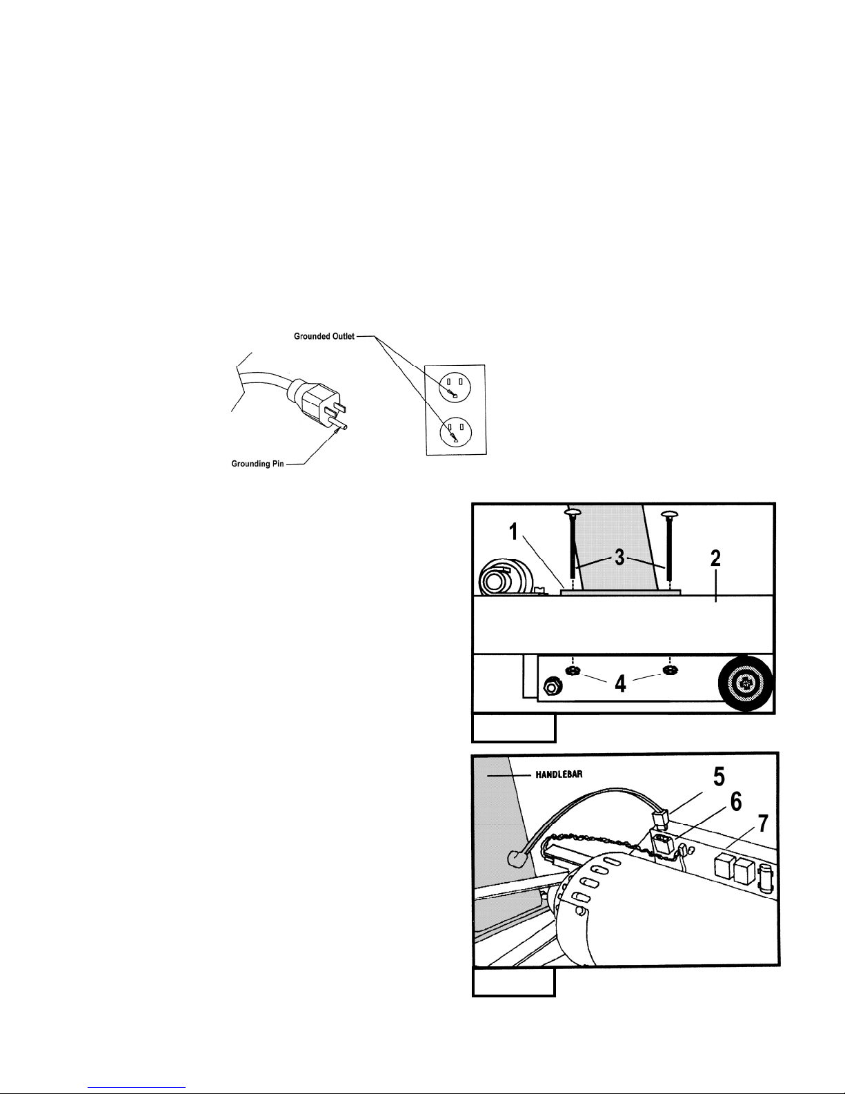
Figure 1:
Carefully place the bottom of the handlebar (1) on the frame (2) so the two
holes in the plate at the bottom of the handlebar line up with the holes in the
frame. Be extremely careful not to damage the speed sensor while
installing the handlebar.
Insert the 3.5” carriage bolts (3) through the handlebar and the frame.
Install a 1/4-20 kep nut (4) to each carriage bolt to keep the handlebar
in place. Follow the same procedure for the other handlebar. Do not
tighten any nuts until both sides are bolted in place.
Figure 2:
With the handlebar in place, plug the wire harness (5) into the socket (6)
on the power supply board (7).
Figure 1
Figure 2
5
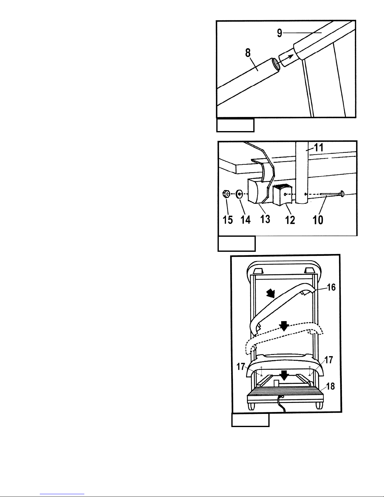
Figure 3:
Take one of the side rails (8) and slide the end with the grip
over the end of the steel tube protruding from the control
panel (9). Make sure the side rail grip touches the control panel.
Figure 4:
Insert one of the 4” carriage bolts (10) through the side rail (11), the side
rail bracket (12) (the foam on the bracket should be at the top, facing
the frame) and finally through the frame (13) . Install a 1” fender washer (14)
and a ¼-20 kep nut (15) to the bolt and hand tighten. Install the other side rail
following the same procedure. Tighten both side rails with a wrench.
Figure 5:
To install the motor cover, stand in front of the treadmill. Pick up
the motor cover (16) so it is level and the word PaceMaster is upside
down. Holding the motor cover level and waist high, tilt it 45 degrees
by lowering your left hand. Then slide it between the handlebars and
lower the motor cover until it is level. Lower the cover all the way,
keeping it level. Screw the two #8x1/2” black sheet metal screws (17)
into the front of the motor cover. Press down on each side of the
motor cover where it meets the black plastic shrouds to lock the Velcro
pads (18) into place.
CAUTION
: Do not raise or lower motor cover without it being level.
Figure 3
Figure 4
Figure 5
6
 Loading...