

PaceMaster Platinum Pro VR, Platinum Pro Owner's Manual
PaceMaster
Platinum Pro VR
OWNER’S MANUAL
Manufactured by: Aerobics Inc., 34 Fairfield Place West Caldwell, NJ 07006, (973) 276-9700
Part # TMP1620 Rev. 04/18/07
Serial # ________________________(Page 8 Fig 7) Date of Purchase ______/______/_____
Dealer Name ___________________________ Dealer Phone # ___________________
www.pacemaster.com

TABLE OF CONTENTS
INTRODUCTION 3
IMPORTANT SAFETY INSTRUCTIONS 4
ASSEMBLY INSTRUCTIONS 5-9
Installation Requirements 5
Unpacking Your Treadmill 5
Tools Required for Assembly 5
Grounding Instructions 5
Assembly Instructions 6-8
Testing Your Treadmill 9
THE PACEMASTER PLATINUM PRO VR CONTROL PANEL 10-13
OPERATING INSTRUCTIONS 14-34
Metric Units 14
Setting Your Weight & Age 14
Warm Up and Cool Down 14
Configuring User ID’s 15-16
Quick Start 17
Timed Workout (Manual) 18
Fat Burn Workouts 19-20
Fat Burn Workout Profiles 21
Cardio Workouts 22-24
Using the Contact Heart Rate Feature 25
HR Performance Review 25
Fitness Evaluator 26
Personal Trainer Workouts 27-30
Personal Trainer Workout Profiles 31
VRCourse’s 32-33
VRCourse Data 34
EXCLUSIVE PACEMASTER FEATURES 35-36
Exercise Preview 35
Aerobic Points 35
Personal Electronic Trainer 35-36
CARE AND MAINTENANCE 37
Deck and Tread Belt Cleaning 37
Lubrication 37
Centering the Tread Belt 37
TROUBLE SHOOTING 38-41
Electronic Error Codes 38-39
Elevation Error Codes 39
Hesitation of the Belt 40
Drive Belt Tension Adjustment 40
Tread Belt Tension Adjustment 41
FREQUENTLY ASKED QUESTIONS 42
PACEMASTER TECHNICAL SPECIFICATIONS 43
2

INTRODUCTION
Congratulations and thank you for choosing PaceMaster – your partner in achieving your fitness goals and mastering your well-being.
PaceMaster’s advanced digital technology allows your treadmill to process information instantly, anticipating and adjusting to meet your
needs. Think of it as your own personal trainer.
PaceMaster’s superior components and US manufacture ensure we produce treadmills of the highest quality while also offering excellent
value for your dollar. PaceMaster treadmills have consistently received praise from a wide range of nationally recognized publications.
To get the most from your PaceMaster, please read this owner’s manual carefully before starting to use the treadmill. The manual contains
important information about the assembly, operation and maintenance of the machine.
Please ensure you read and fully understand all safety information.
important safety warnings throughout the manual. Failure to read and understand these warnings may result in personal injury or damage
to your treadmill.
Tip indicates a useful suggestion when installing, maintaining or using your treadmill.
Your PaceMaster treadmill is capable of varying your workout by changing speed, incline and time. It can also measure the effect of your
workout in a number of different ways. For example “Aerobic Points” (see page16) is a well tested method to set workout goals based on a
desired level of overall fitness. Your PaceMaster treadmill can automatically calculate Aerobic Points for you. In this way your treadmill acts
like your own personal trainer.
Please take the time to familiarize yourself with the range of functions available. This will help you work with your PaceMaster treadmill for
maximum efficiency to achieve your fitness goals and master your well-being.
We wish you an enjoyable and rewarding partnership with your PaceMaster treadmill.
This treadmill is in compliance with EN 957-2 class H.
The PaceMaster Platinum Pro VR treadmill is designed for home use only.
DANGER, CAUTION, or WARNING indicates
3

IMPORTANT SAFETY INSTRUCTIONS
Read these instructions before using your treadmill
CAUTION: Before starting any exercise program, contact your personal physician and have a complete physical. This is highly
recommended if you have not been on a regular exercise program within the last year, or are over 35 years of age, or are overweight.
CAUTION: If at any time during your exercise program you find the exercise abnormally difficult or you encounter dizziness, feel
faint, experience chest pains, feel as if your heart may be skipping beats, you experience forced heavy breathing after minimal exercise or
severe pain in your legs, ankles, knees, etc. STOP EXERCISING and consult your physician.
WARNING: To reduce the risk of burns, fire, electrical shock or injury:
• Never operate your PaceMaster treadmill without clipping the magnetic safety key to your clothing at waist level.
• Your PaceMaster treadmill is not designed for use by children under the age of 18 without strict parental supervision.
• Close supervision is necessary when the treadmill is used by or near children, disabled persons or pets.
• Use your PaceMaster treadmill only for its intended use as described in this manual. Do not use accessories or attachments not
recommended by Aerobics, Inc.
• Never operate your PaceMaster treadmill if it has a damaged cord or plug, if it is not operating properly, if it has been dropped or
damaged or if it has been immersed in water. Should any of these occur, contact your authorized PaceMaster retailer or service
center for examination or repair.
• Keep the cord away from heated surfaces.
• Never drop or insert any object into any opening on the treadmill.
• Do not use outdoors.
• Always unplug your PaceMaster treadmill during an electrical storm or during extended periods of non-use.
• Do not operate where aerosol (spray) products are being used or where oxygen is being administered.
• Position the treadmill with a minimum of 4 feet (1219mm) of clearance between the rear of the treadmill and any wall or obstruction.
• Do not allow anyone to reach under or be too near your PaceMaster while it is in use.
• Do not attempt to mount or dismount the tread belt while it is running.
• Never allow more than one person on your PaceMaster treadmill at any time.
• Never move the treadmill while it is plugged into the electrical outlet.
• When you are finished exercising, leave your PaceMaster treadmill in a non-elevated position to avoid toys and other objects from
becoming trapped beneath.
• Wear appropriate running or walking shoes and attire while exercising.
• The treadmill should be turned off after each use by removing the safety magnetic key.
• Never apply lubricant to the belt and deck. It is permanently lubricated at the factory and is maintenance free.
4

ASSEMBLY INSTRUCTIONS
Installation Requirements
Your PaceMaster should be installed indoors on a flat, level surface near a 120Volt/ 15Amp outlet. PaceMaster requires a dedicated, nonswitched outlet that is not part of a GFI (Ground Fault Interrupter) circuit, preferably no more than 5 feet from the outlet to eliminate the
need for an extension cord. You must have a minimum of 4 feet of clearance between the rear of the treadmill and any wall or obstruction.
TIP: If you are installing your PaceMaster on a carpeted surface, use a treadmill mat or a scrap piece of carpet underneath the treadmill to
avoid soiling of the carpet. Deep pile carpet is not recommended.
Unpacking Your Treadmill
The PaceMaster treadmill is packed in five pieces:
• Frame assembly
• Front handlebar assembly with Control Panel
• Two side rails (1 Left, 1 Right)
• Motor cover
• Hardware package
• Polar Heart Rate Transmitter.
Before assembling your treadmill, open the hardware package and verify that the contents of the package match the hardware legend
included in the hardware package. NOTE: there will be an extra 3/16” Hex Wrench in the hardware package. If any parts are missing,
contact the authorized PaceMaster retailer where you purchased your PaceMaster treadmill.
Tools Required for Assembly
• 3/16” T – handle Hex wrench (included)
• 7/32” Hex wrench (included)
• Phillips screwdriver (# 2 tip)
• 7/16” combination wrench
Grounding Instructions
DANGER: This product must be properly grounded. If it should malfunction or
become inoperable, grounding provides a path of least resistance for electric current to
reduce the risk of electric shock. This product is equipped with a cord having an
equipment-grounding conductor and a grounding plug. The plug must be plugged into
an appropriate outlet that is properly installed and grounded in accordance with all local
codes and ordinances. See example to the right.
WARNING: Improper connection of the equipment grounding-conductor can result in a risk of electrical shock. Check with a
qualified electrician or serviceman if you are in doubt as to whether the product is properly grounded. Do not modify the plug provided with
the product. If it will not fit the outlet, have a proper outlet installed by a qualified electrician. This product is rated for more than 15
amperes and is for use on a circuit having a nominal rating of 120 volts. It is factory equipped with a specific electric cord and plug to
permit connection to a proper electric circuit. Make sure that the product is connected to an outlet having the same configuration as the
plug. No adapter should be used with this product. Attempting to bypass it with an adapter or in any way defeating its purpose can
result in a serious shock hazard.
As a safety precaution, unplug the treadmill during electrical storms or if the treadmill will not be in use for periods greater than one week.
CAUTION: If you need to use an extension cord it must be a 14 gauge, three wire cord, no longer than 12 feet.
5
ASSEMBLY INSTRUCTIONS
Assembly
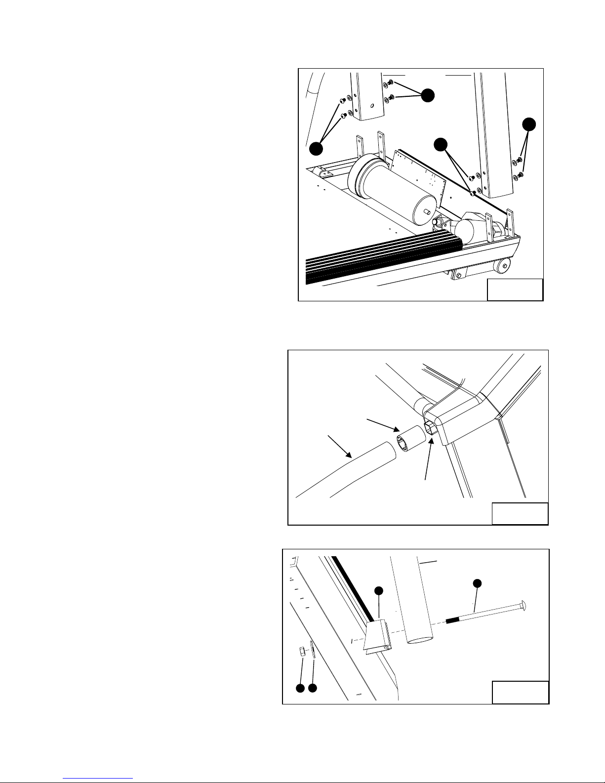
Step One: (see figure 1)
Carefully lower the handlebar on to its mounting brackets as
shown in figure 1. The mounting brackets must slide inside the
handle bar. With the handle bar in place install 2 screws (A) with
washers into both handlebar uprights as shown, do not tighten
these screws yet. Install 2 screws (B) with washers into both
handlebar uprights as shown; The following MUST be done in the
Order it is written.
Tighten the 4 screws (A) as shown in figure 1.
Tighten the 4 screws (B) as shown in figure 1.
Step Two: (see figure 2)
Slide the side rail adaptors all the way onto the square handle
bar support tube. The side rails are labled left and right, slide
the side rails over the side rail adaptors on their respective
sides. The grip on the side rail must slide inside the control
panel till it can go no more.
Step Three: (see figure 3)
Insert carriage bolt (G) through the hole in the bottom of the
side rail. Slide the side rail mounting bracket (H) on to the
bolt as shown. Push the carriage bolt through the frame rail
until it is protruding through the other side. Install the fender
washer (I) and the kep nut (J) on the threaded end of the
bolt. Tighten the 2 nuts (J) as shown in figure 3.
J
A
SIDE RAIL
I
SIDE RAIL
ADAPTOR
H
HANDLEBAR
B
HANDLE BAR
SUPPORT TUBE
A
SIDE RAIL
G
Figure 1
Figure 2
Figure 3
B
6
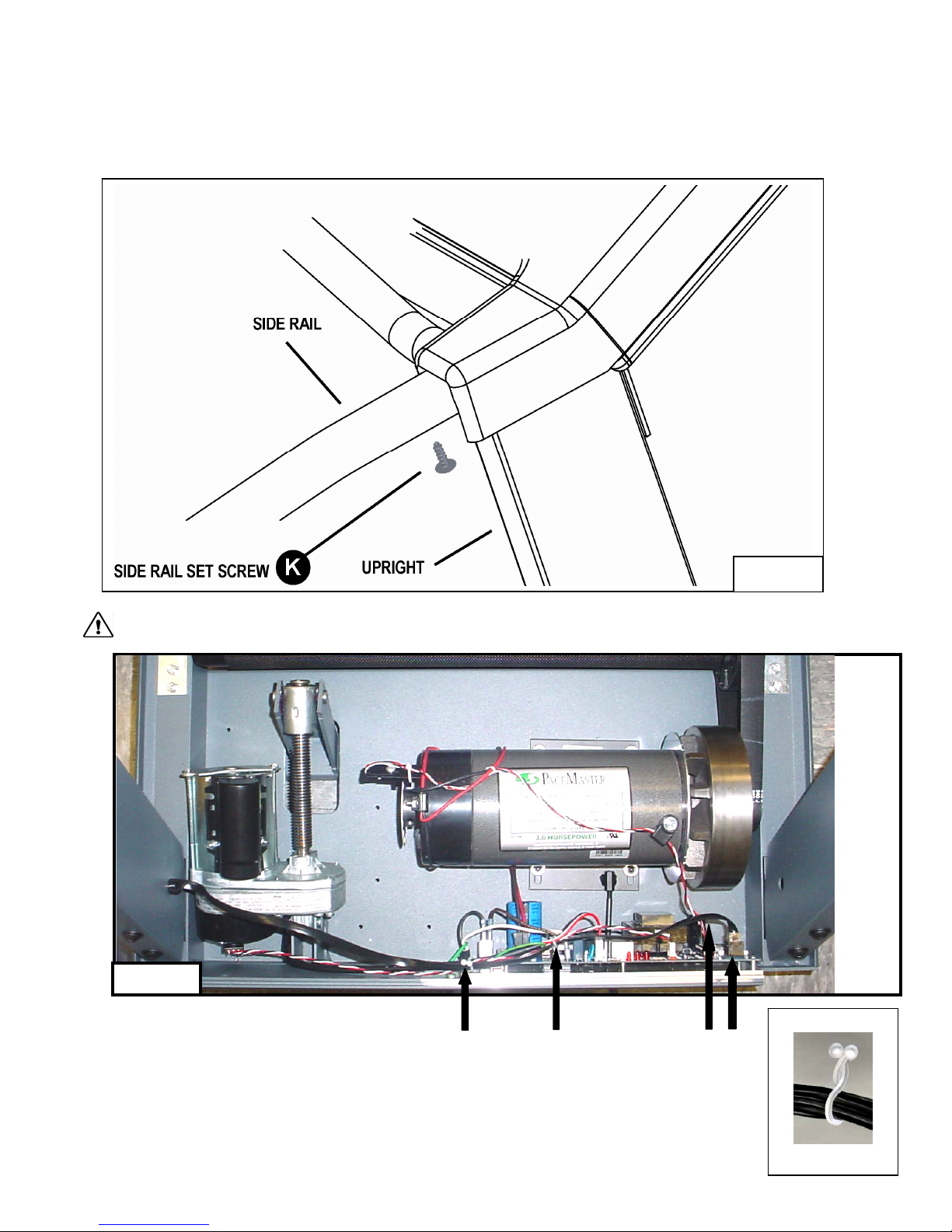
Step Four: (see figure 4)
The grip on the side rail must slide inside the control panel till it can go no more. Install the set screws “K” #8 x ½” into the predrilled hole
on the bottom of each side rail as shown in figure 4. You must drive the screw all of the way in.
CAUTION: The treadmill MUST be unplugged.
Figure 5
Step Five: (see figure 5)
With the handlebar bolted in place, plug the black wire harness (C) into the socket (D) on the power supply board.
Twist open the purse lock clip at (E), insert the wire harness (C), confirm the wire harness is positioned as shown at
point (D) and twist close the purse lock clip. Follow the same procedure for purse lock clip (F).
F
E
C
Figure 4
Purse Lock Clip
D
Shown Closed
7
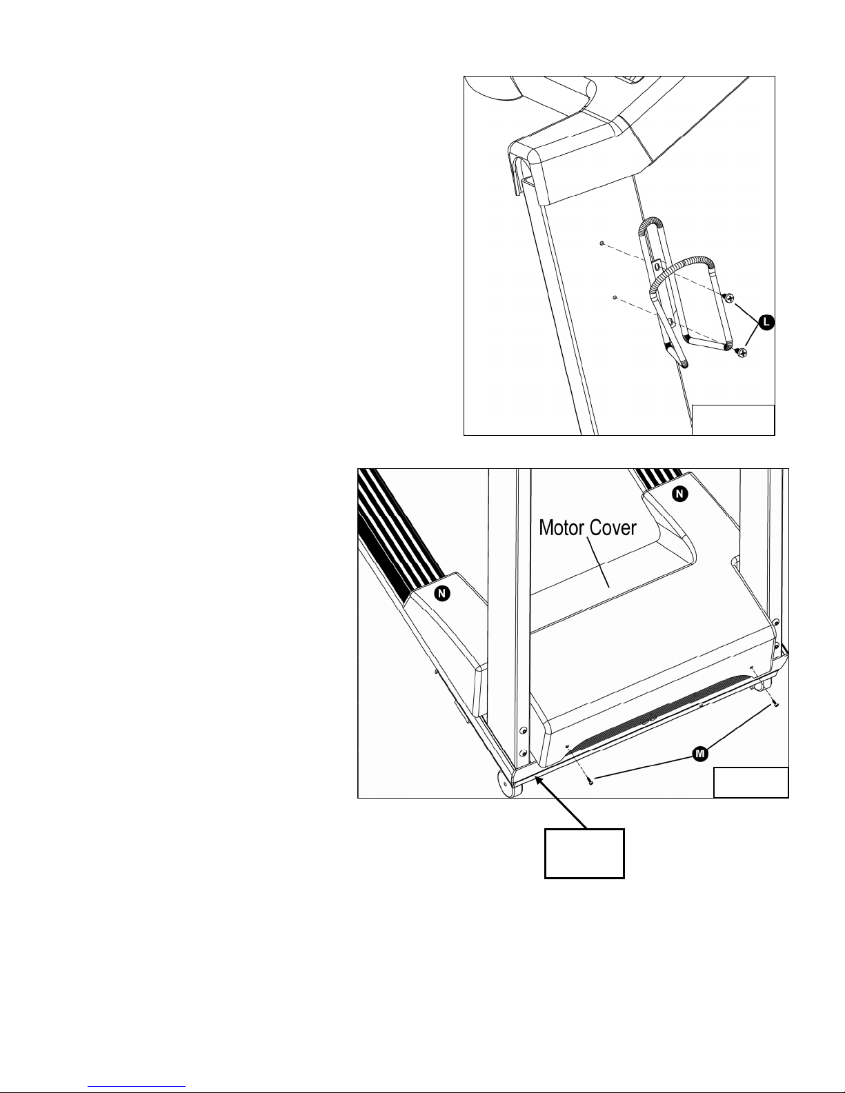
Step Six: (see figure 6)
Remove the 2 Phillips head screws (L) from the right handle bar upright.
Install the water bottle cage using screws (L) as shown in figure 6.
Step Seven: (see figure 7)
Position the grey motor cover as shown in figure 7.
Use two #8 x 3/8 screws from the hardware kit to
secure the motor cover at the two points “M” in fig. 7.
Press down at both points “N” to secure the Velcro
pads.
Figure 6
Figure 7
Serial
Number
8
Testing Your Treadmill
Your PaceMaster has been adjusted and tested at the factory. However, due to changes that can occur during shipment, it should be
tested prior to use. Once you have assembled your treadmill and it is located where it will be used, proceed as follows. (Do not make any
adjustments unless necessary.) For the purpose of this test, DO NOT
on the tread belt.
Follow the steps below to confirm proper operation of your treadmill after assembly.
Step One:
After your treadmill is in place and plugged in to the wall outlet, insert the magnetic safety key into the recess on the control panel.
Step Two:
stand on the tread belt. Once tested, always start and finish
Press the Incline
(ENTER)
button.
buttons to set your weight and the Speed buttons to set your age, then press the
Step Three:
Set the workout speed by pressing the SPEED
button until the SPEED display shows 2.5 mph.
Step Four:
(QUICK)
Press the START
button. Within a few seconds, the tread belt will begin to move. The speed display will flash until the tread belt
has reached the set speed.
Step Five:
After the treadmill has reached 2.5 mph, observe the tread belt to make sure it is reasonably centered. If the tread belt is not reasonably
(RESET)
centered, press the STOP
button and refer to “Centering the Tread Belt” in the Care and Maintenance section of this manual.
Once the tread belt is reasonably centered, run the treadmill at 2.5 mph for 2 minutes to be sure it remains centered.
Step Six:
To test the elevation, the tread belt must be moving. Press the incline up
button to raise the elevation to 5% incline. The elevation
will be displayed in the INCLINE display window. Once it reaches 5%, press the incline down
then return the incline to 0%. If the treadmill does not elevate, or displays “Err” in the incline display consult the troubleshooting section of
this manual.
Step Seven:
Press STOP
(RESET)
you are now ready to use your treadmill.
button to reduce the incline to -3%,
9
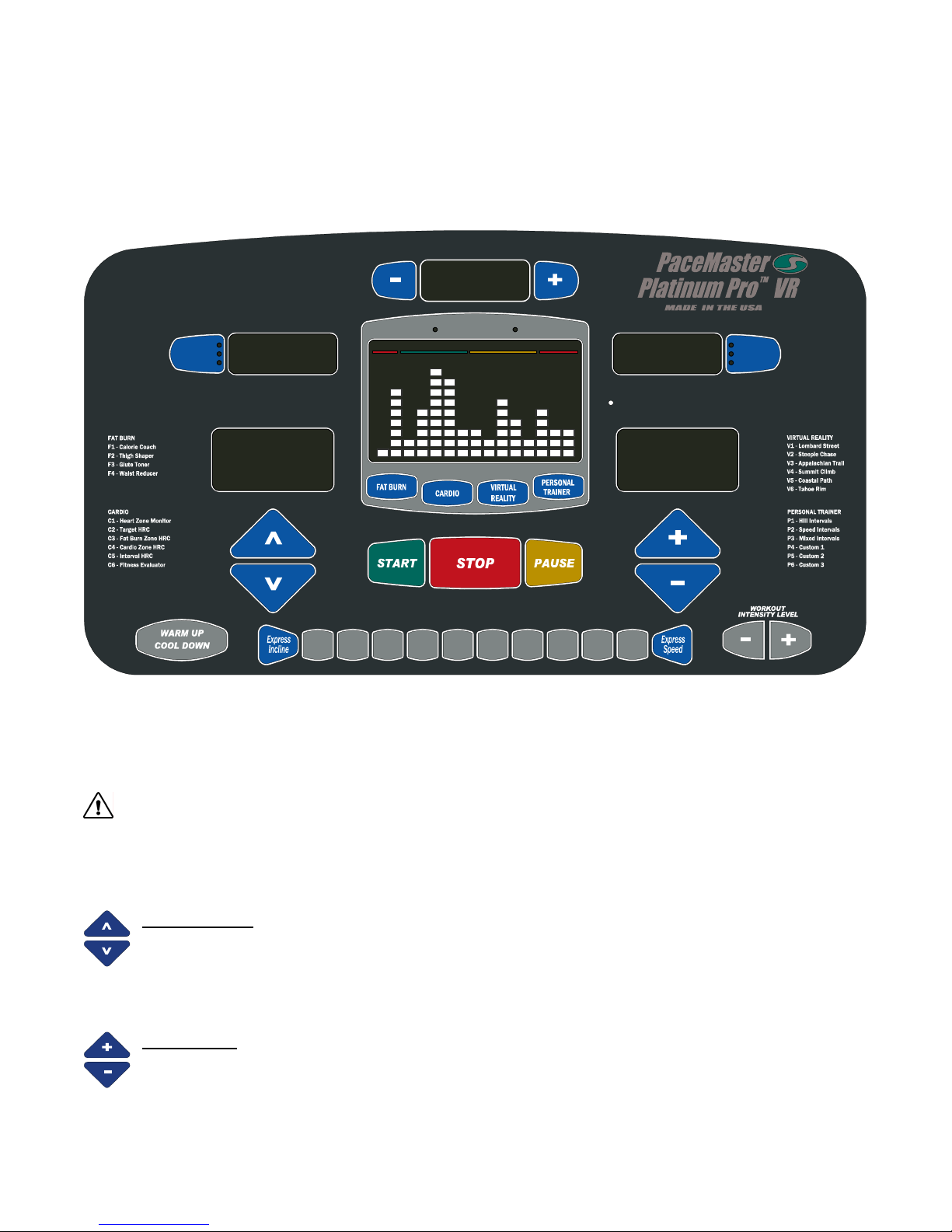
THE PACEMASTER PLATINUM PRO VR CONTROL PANEL
Although your PaceMaster has many advanced features to provide versatility in meeting exercise needs, basic operation is extremely
easy. Basic operation involves setting your TIME and SPEED goals, then pressing the START button. Your PaceMaster will gradually
accelerate to the set speed, maintain that speed until the timer counts to zero and then gradually come to a complete stop. During your
exercise, your time remaining, current speed and incline, distance traveled, calories burned, Aerobic Points earned, heart rate and average
speed are displayed.
TIMER
Distance
Heart Rate
(USER ID)
PROFILE
HEART RATE ZONE 70% to 85%< 55% 55% to 69% > 85%
2.5
INCLINE SPEED
Max Max
150
Set Weight
(QUICK)
0123456789
Cool DownWarm Up
uSA
Calories
Aerobic Pts
PaceAvg Speed
40
Set Age
(ENTER)(RESET)
MAGNETIC SAFETY KEY - The MAGNETIC SAFETY KEY, with its red cord and garment clip, is an important safety feature. It is also the
ON/OFF switch. To power up your treadmill, first attach the garment clip to your clothing at waist level then insert the MAGNETIC
SAFETY KEY into the round recess on the control panel. This MAGNETIC SAFETY KEY provides a means of powering down the treadmill
in an emergency situation. This treadmill will not operate unless the MAGNETIC SAFETY KEY is engaged. During exercise, an
emergency stop can be made at any time by pulling on the cord to release the key from its slot.
CAUTION: Using the key to stop the treadmill is an emergency procedure only! To end your exercise routine normally, press
the STOP button or allow the timer to count down to zero. Once the belt has come to a complete stop, remove the MAGNETIC SAFETY
KEY to turn off the treadmill. When not in use, store the MAGNETIC SAFETY KEY in a safe place to prevent unauthorized use.
BUTTONS
INCLINE ▲and ▼ – 1) When the safety magnetic key is inserted, the Set Weight LED light will flash, prompting you to set your
weight. Use these buttons to adjust weight, then press ENTER. 2) Once the user weight has been entered, use these buttons
to increase or decrease INCLINE in 0.5% increments to simulate exercising up hill. INCLINE can be changed at any time during
your workout. At the end of your workout, the INCLINE setting will automatically return to 0%.
Note: If the magnetic safety key is removed, the incline will not return to 0%. This automatic feature will only occur if the program time has
run out or if the STOP key is pressed.
SPEED + and − 1) When the safety magnetic key is inserted, the Set Age LED light will flash, prompting you to set your age.
Use these buttons to adjust weight, then press ENTER. 2) Once the user age has been entered, use these buttons to increase
or decrease SPEED in 0.1 mph increments. SPEED can be adjusted at any time during your workout.
Note: Because the treadmill’s computer controls the SPEED during the warm up and cool down phases of your workout., these
buttons are inoperable in those modes.
10
T
THE PACEMASTER PLATINUM PRO VR CONTROL PANEL (cont’d)
(QUICK)
(ENTER)
For details, refer to the WORKOUTS section in this manual. 3) During a workout, pressing this button will PAUSE your workout, putting it
"on hold". The treadmill and the timer will stop but retains the distance, calories burned, Aerobic Points earned and Average Speed thus
far, as well as the speed and incline settings and remaining time. The symbol -P- flashes in the SPEED display to indicate the PAUSE
feature has been activated. To resume your workout where you left off, press START.
select the desired workout time, adjustable in 1 minute increments. 2) Once a Fat Burn, Cardio or Personal Trainer program has been
selected, use these buttons to set the desired workout time from 20 to 60 minutes, adjustable in 5 minute increments. 3) When
programming a Custom workout the buttons are used to adjust segment time.
PROFILE display window when a WARM UP and/or COOL DOWN mode is selected. 3) During WARM UP, pressing the WARM UP
COOL DOWN button discards the remaining Warm Up time and advances you to the main workout phase. During the main workout,
pressing the WARM UP COOL DOWN button discards the remaining time and starts the Cool Down phase. For details, refer to the USER
ID and/or WARM UP and COOL DOWN section in this manual.
▼buttons to increase or decrease incline or the SPEED + or - buttons to increase or decrease speed, press these buttons, then the
numbered button(s) 0-9 for express changes.
INTENSITY LEVEL
section in this manual. Note: The included chest strap must be worn and a heart rate signal must be detected in order for these programs
to be operational.
section in this manual.
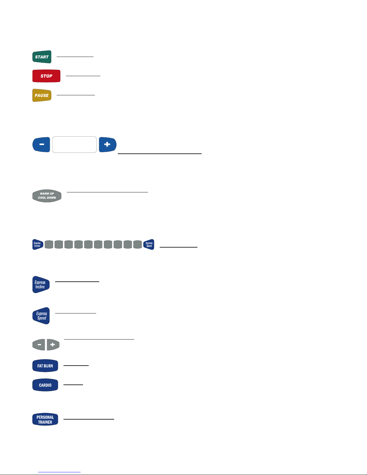
START (QUICK) – 1) Use this button to QUICK START your workout with the press of one button. 2) In all other program
modes, use this button to START your workout after the desired time, speed and incline have been entered.
(RESET)
STOP (RESET) – 1) Press this button to end your workout. 2) If pressed when the treadmill is stopped, it will RESET the
display.
PAUSE (ENTER) – 1) When you insert the magnetic safety key, use this button to ENTER your weight. 2) In all of the FAT
BURN, CARDIO, PERSONAL TRAINER or TIMED (MANUAL) workouts, press this key to ENTER the desired workout time.
TIMER PLUS AND MINUS BUTTONS - 1) In a Timed Workout (Manual), press these buttons to
(USER ID)
WARM UP COOL DOWN (USER ID) – 1) After the magnetic safety key is inserted, press this button to select your User ID
#, 1, 2, 3, or 4. 2) Prior to starting your program, this button allows you to add or remove a 5-minute Warm Up and/or 5minute Cool Down phase to your workout. The WARM UP and/or COOL DOWN indicator LED lights will illuminate in the
0123456789
EXPRESS KEYS
– As an alternative to continually pressing the INCLINE ▲or
EXPRESS INCLINE
–. For example, if you want to adjust the incline to 10%, press the EXPRESS INCLINE button, then 1, then
0. The incline will automatically increase to 10%. The EXPRESS INCLINE buttons adjusts incline in 1.0% increments. To
adjust the incline to -2.0%, press EXPRESS INCLINE, then 2, then press the INCLINE ▼button.
EXPRESS SPEED – For example, if you choose to increase the speed to 5.0 mph, press the EXPRESS SPEED button, then 5,
then 0. The speed will automatically be increased to 5 mph. The EXPRESS SPEED buttons adjust speed in 0.1 mph
increments. To adjust speed to 5.3 mph, press EXPRESS SPEED, then 5, then 3.
WORKOU
WORKOUT INTENSITY LEVEL – 1) Use these buttons to select the desired workout intensity level (1 through 9), then
press START to begin your workout. For details, refer to the TIMED WORKOUT (MANUAL), FAT BURN, CARDIO and
PERSONAL TRAINER sections in this manual.
FAT BURN – Press this button to choose one of the four FAT BURN programs, Calorie Coach, Thigh Shaper, Glute Toner
or Waist Reducer. For details, refer to the FAT BURN WORKOUT section in this manual.
CARDIO – Press this button to choose one of the six CARDIO workouts; Heart Zone Monitor, Target HRC,
Fat Burn Zone HRC, Cardio Zone HRC, Interval HRC or Fitness Evaluator. For details, refer to the CARDIO WORKOUT
PERSONAL TRAINER
– Press this button to choose one of the six PERSONAL TRAINER workouts; Hill Intervals, Speed
Intervals, Mixed Intervals, Custom 1, Custom 2 or Custom 3. For details, refer to the PERSONAL TRAINER WORKOUTS
11

THE PACEMASTER PLATINUM PRO VR CONTROL PANEL (cont’d)
VIRTUAL REALITY - Press this button choose one of the 6 VR Courses. For details, refer to the VIRTUAL REALITY
Courses section in this manual.
Distance
Heart Rate
Avg Speed
the workout you have chosen or your heart rate. 2) During your workout, press this button to select the desired feedback you want
displayed; Distance, Heart Rate, or Average Speed.
Calories
Aerobic Pts
Pace
Points or average pace for the workout you have chosen. 2) During your workout, press this button to select the desired feedback you
want displayed; Calories, Aerobic Points, or Average pace. 3) Press this button to change between English units and Metric units. For
details, refer to the METRIC UNITS section in this manual.
DISPLAYS
TIMER – This window displays the chosen workout time in minutes and seconds (mm:ss) up to 59 minutes and 59 seconds. Times of 1
hour to a maximum of 4 hours are displayed as hours and minutes (
minutes is displayed as -1:15. In QUICK START, the TIMER will count up, displaying the elapsed time. In all other program modes, the
TIMER will count down, displaying the remaining time. If a Warm Up and/or Cool Down mode is chosen, the TIMER will display as a 5minute countdown for the warm up phase, a countdown for the main exercise phase and then a 5-minute countdown for the cool down
phase.
PROFILE – This window displays the program PROFILE of the chosen Fat Burn, Cardio, Personal Trainer program. In Quick Start, the
PROFILE displays a quarter mile track. In a Timed (Manual) program, the PROFILE displays a OneLap track. For details, refer to the
OneLap Track section in this manual.
LEFT DATA DISPLAY
of that workout, based on the chosen time and intensity (level). 2) During the workout, this window can display actual distance, Heart Rate,
or Average Speed. The current result displayed in this window will be indicated by an illuminated LED light. 3) When programming a
Custom workout this window will display total workout time.
RIGHT DATA DISPLAY
Aerobic Points or average pace for the workout you have chosen. 2) During the workout, this window can display calories expended,
Aerobic Points or current pace. The current result displayed in this window will be indicated by an illuminated LED light.
SPEED – This window displays SPEED from 0.5 mph to 12.0 mph. prior to beginning a workout, the starting SPEED is displayed. Once
your workout has begun, the current SPEED is displayed.
INCLINE – This window displays INCLINE from 0% to 15.0%. Prior to beginning a workout, the starting INCLINE is displayed. Once your
workout has begun, the current INCLINE is displayed.
INDICATOR LED LIGHTS
Set Weight – Within seconds of the magnetic safety key being inserted, the SET WEIGHT LED indicator light flashes and the last entered
weight appears in the INCLINE display window. Weight can be adjusted by pressing the INCLINE ▲or ▼buttons. Once your weight is
displayed, press PAUSE (ENTER).
Set Age – Within seconds of the magnetic safety key being inserted, the SET AGE LED indicator light flashes and the last entered age
appears in the SPEED display window. Age can be adjusted by pressing the SPEED + or - buttons. Once your age is displayed, press
PAUSE (ENTER).
LEFT DATA SELECT – 1) Prior to beginning your workout, press this button to see the predicted distance, average speed for
RIGHT DATA SELECT – 1) Prior to beginning your workout, press this button to see the predicted caloric expenditure, Aerobic
–
h: mm), with the dash as the first digit. For example, one hour and 15
–1) Prior to pressing the START button, the Left Data window will display the predicted distance or average speed
–1) Prior to pressing the START button, the Right Data window will display the predicted caloric expenditure,
12

THE PACEMASTER PLATINUM PRO VR CONTROL PANEL (cont’d)
INCLINE Max
number displayed in the INCLINE display window is the maximum incline that will be encountered for the program and level chosen.
SPEED Max – The SPEED Max LED indicator light is illuminated when a Fat Burn, Cardio, Personal Trainer workout is selected. The
number displayed in the SPEED display window is the maximum speed that will be encountered for the program and level chosen.
WARM UP and COOL DOWN
a WARM UP and/or COOL DOWN mode is selected.
– The INCLINE Max LED indicator light is illuminated when a Fat Burn, Cardio, Personal Trainer workout is selected. The
– The WARM UP and/or COOL DOWN indicator LED lights will flash in the PROFILE display window when
13
 Loading...