

PaceMaster Platinum ProClub Owner's Manual
PaceMaster
Platinum ProClub
OWNER’S MANUAL
Manufactured by: PaceMaster LLC, 34 Fairfield Place, West Caldwell, NJ 07006, (973) 276-9700
Part # TMP1638 Rev. 09/16/10
www.pacemaster.com

TABLE OF CONTENTS
INTRODUCTION 3
IMPORTANT SAFETY INSTRUCTIONS 4
ASSEMBLY INSTRUCTIONS 5-18
Unpacking Your Treadmill 5
Installation Requirements 6
Tools Required for Assembly 6
Grounding Instructions 6
Assembly Instructions 7-17
Testing Your Treadmill 18
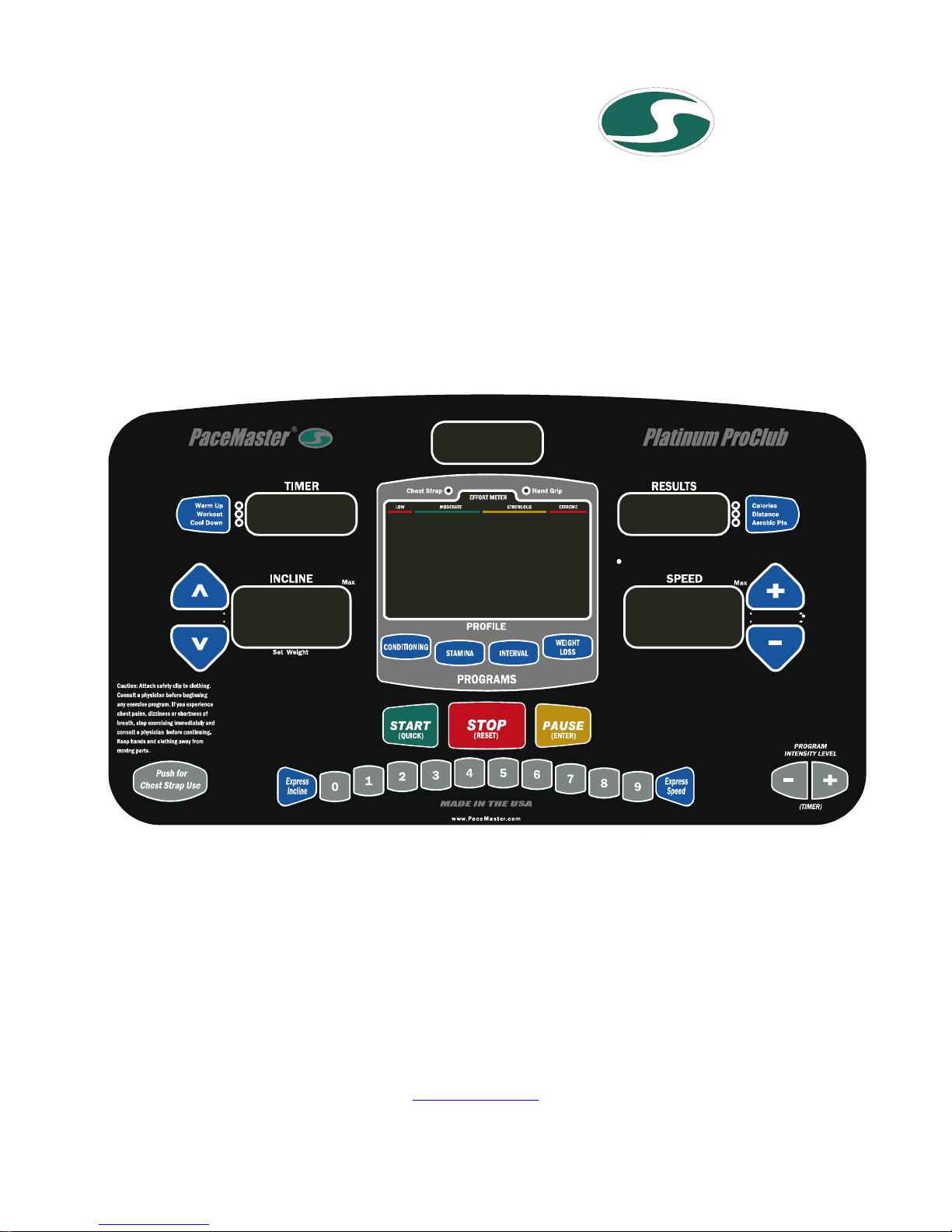
THE PACEMASTER PLATINUM PROCLUB CONTROL PANEL 19-21
OPERATING INSTRUCTIONS 22-27
Metric Units 22
Setting Your Weight 22
Warm Up and Cool Down 22
Quick Start 23
Timed Workout (Manual) 24
Using the Programmed Workouts 25
Programmed Workout Profiles 26
Using a wireless chest strap transmitter 27
Using the Contact Heart Rate Feature 27
EXCLUSIVE PACEMASTER FEATURES 28-29
Exercise Preview 28
Aerobic Points 28
Personal Electronic Trainer 28-29
CARE & MAINTENANCE 30-31
Deck and Tread Belt Cleaning 30
Contact Heart Rate Sensor Cleaning 30
Lubrication 30
Centering the Tread Belt 31
TROUBLE SHOOTING 32-35
Electronic Error Codes 32-34
Elevation Error Codes 33-34
Hesitation of the Belt 34
Drive Belt Tension Adjustment 35
Tread Belt Tension Adjustment 35
FREQUENTLY ASKED QUESTIONS 36
PACEMASTER TECHNICAL SPECIFICATIONS 37
2

INTRODUCTION
Congratulations and thank you for choosing PaceMaster – your partner in achieving your fitness goals and mastering your well-being.
PaceMaster’s advanced digital technology allows your treadmill to process information instantly, anticipating and adjusting to meet your
needs. Think of it as your own personal trainer.
PaceMaster’s superior components and US manufacture ensure we produce treadmills of the highest quality while also offering excellent
value for your dollar. PaceMaster treadmills have consistently received praise from a wide range of nationally recognized publications.
To get the most from your PaceMaster, please read this owner’s manual carefully before starting to use the treadmill. The manual contains
important information about the assembly, operation and maintenance of the machine.
Please ensure you read and fully understand all safety information.
important safety warnings throughout the manual. Failure to read and understand these warnings may result in personal injury or damage
to your treadmill.
Tip indicates a useful suggestion when installing, maintaining or using your treadmill.
Your PaceMaster treadmill is capable of varying your workout by changing speed, incline and time. It can also measure the effect of your
workout in a number of different ways. For example “Aerobic Points” (see page 28) is a well tested method to set workout goals based on a
desired level of overall fitness. Your PaceMaster treadmill can automatically calculate Aerobic Points for you. In this way your treadmill acts
like your own personal trainer.
Please take the time to familiarize yourself with the range of functions available. This will help you work with your PaceMaster treadmill for
maximum efficiency to achieve your fitness goals and master your well-being.
We wish you an enjoyable and rewarding partnership with your PaceMaster treadmill.
This treadmill is in compliance with EN 957-2 class H.
DANGER, CAUTION, or WARNING indicates
3

IMPORTANT SAFETY INSTRUCTIONS
Read these instructions before using your treadmill
CAUTION: Before starting any exercise program, contact your personal physician and have a complete physical. This is highly
recommended if you have not been on a regular exercise program within the last year, or are over 35 years of age
, or are overweight.
CAUTION: If at any time during your exercise program you find the exercise abnormally difficult or you encounter dizziness, feel
faint, experience chest pains, feel as if your heart may be skipping beats, you experience forced heavy breathing after minimal exercise or
severe pain in your legs, ankles, knees, etc. STOP EXERCISING and consult your physician.
WARNING: To reduce the risk of burns, fire, electrical shock or injury:
• Never operate your PaceMaster treadmill without clipping the magnetic safety key to your clothing at waist level.
• Your PaceMaster treadmill is not designed for use by children under the age of 18 without strict parental supervision.
• Close supervision is necessary when the treadmill is used by or near children, disabled persons or pets.
• Use your PaceMaster treadmill only for its intended use as described in this manual. Do not use accessories or attachments not
recommended by PaceMaster LLC.
• Never operate your PaceMaster treadmill if it has a damaged cord or plug, if it is not operating properly, if it has been dropped or
damaged or if it has been immersed in water. Should any of these occur, contact your authorized PaceMaster retailer or service
center for examination or repair.
• Keep the cord away from heated surfaces.
• Never drop or insert any object into any opening on the treadmill.
• Do not use outdoors.
• Always unplug your PaceMaster treadmill during an electrical storm or during extended periods of non-use.
• Do not operate where aerosol (spray) products are being used or where oxygen is being administered.
• Position the treadmill with a minimum of 4 feet (1219mm) of clearance between the rear of the treadmill and any wall or obstruction.
• Do not allow anyone to reach under or be too near your PaceMaster while it is in use.
• Do not attempt to mount or dismount the tread belt while it is running.
• Never allow more than one person on your PaceMaster treadmill at any time.
• Never move the treadmill while it is plugged into the electrical outlet.
• When you are finished exercising, leave your PaceMaster treadmill in a non-elevated position to avoid toys and other objects from
becoming trapped beneath.
• Wear appropriate running or walking shoes and attire while exercising.
• The treadmill should be turned off after each use by removing the safety magnetic key.
4
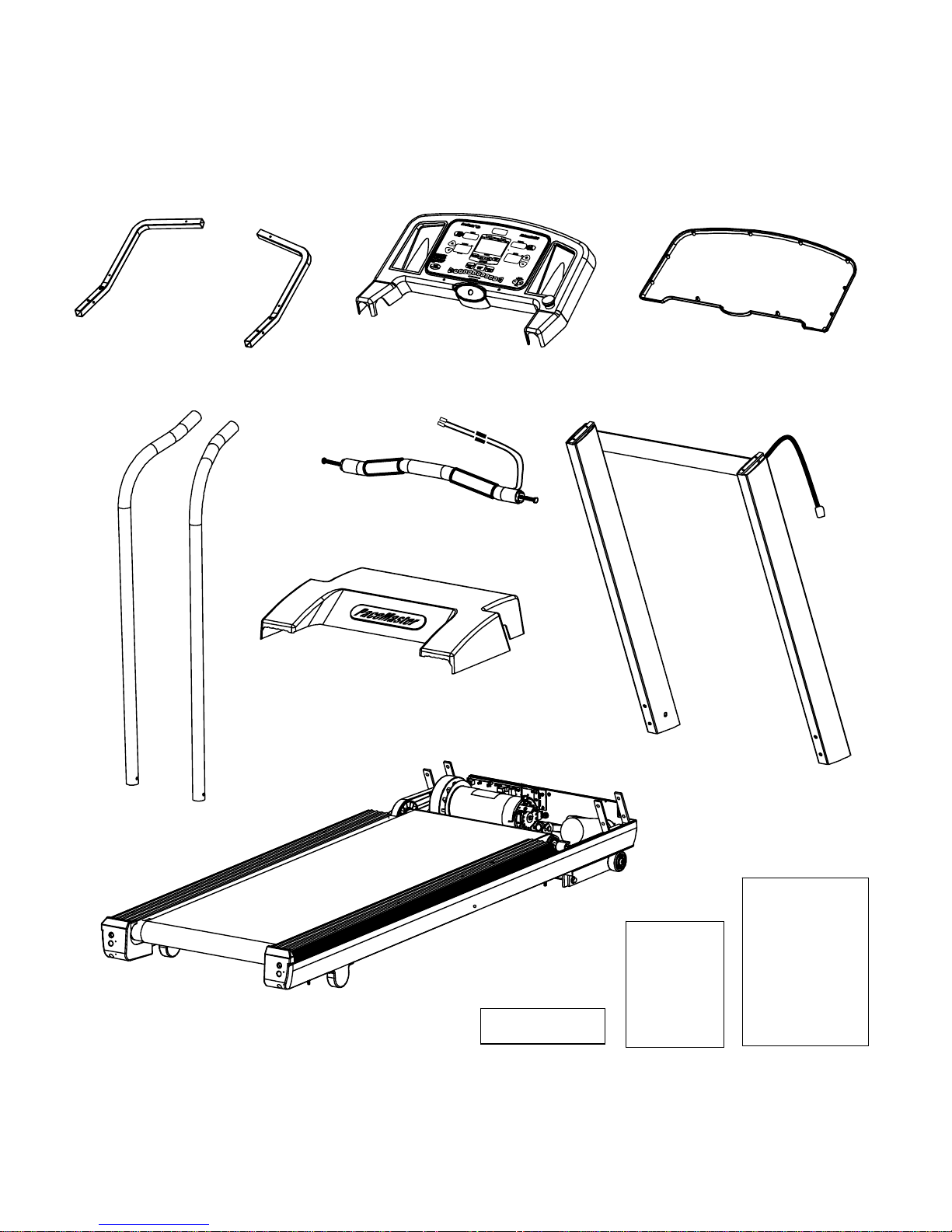
ASSEMBLY INSTRUCTIONS
Unpacking Your Treadmill
Confirm that all of the items pictured below were packed in the box
Panel Support Tube (Left and Right)
Side Rail (Left and Right)
Before assembling your treadmill, open the hardware package and verify that the contents of the package match the hardware legend
included in the hardware package. If any parts are missing, contact the authorized PaceMaster retailer where you purchased your
PaceMaster treadmill.
Ergo Bar
Motor Cover
Treadmill Base
Control Panel Front Control Panel Back
Upright Assembly
Hardware Kit
Chest strap
Owners
Manual
5
ASSEMBLY INSTRUCTIONS (cont’d)
Installation Requirements
Your PaceMaster should be installed indoors on a flat, level surface near a 120Volt/ 15Amp outlet. PaceMaster requires a dedicated, nonswitched outlet, that is not part of a GFI (Ground Fault Interrupter) circuit, preferably no more than 5 feet from the outlet to eliminate the
need for an extension cord. You must have a minimum of 4 feet of clearance between the rear of the treadmill and any wall or obstruction.
TIP: If you are installing your PaceMaster on a carpeted surface, use a treadmill mat or a scrap piece of carpet underneath the treadmill to
avoid soiling of the carpet. Deep pile carpet is not recommended.
Tools Required for Assembly
3/16" Allen wrench, t-handle (supplied)
•
7/32” Allen wrench (supplied)
•
7/16” combination wrench
•
•
Phillips head screwdriver
Slotted Head Screwdriver
•
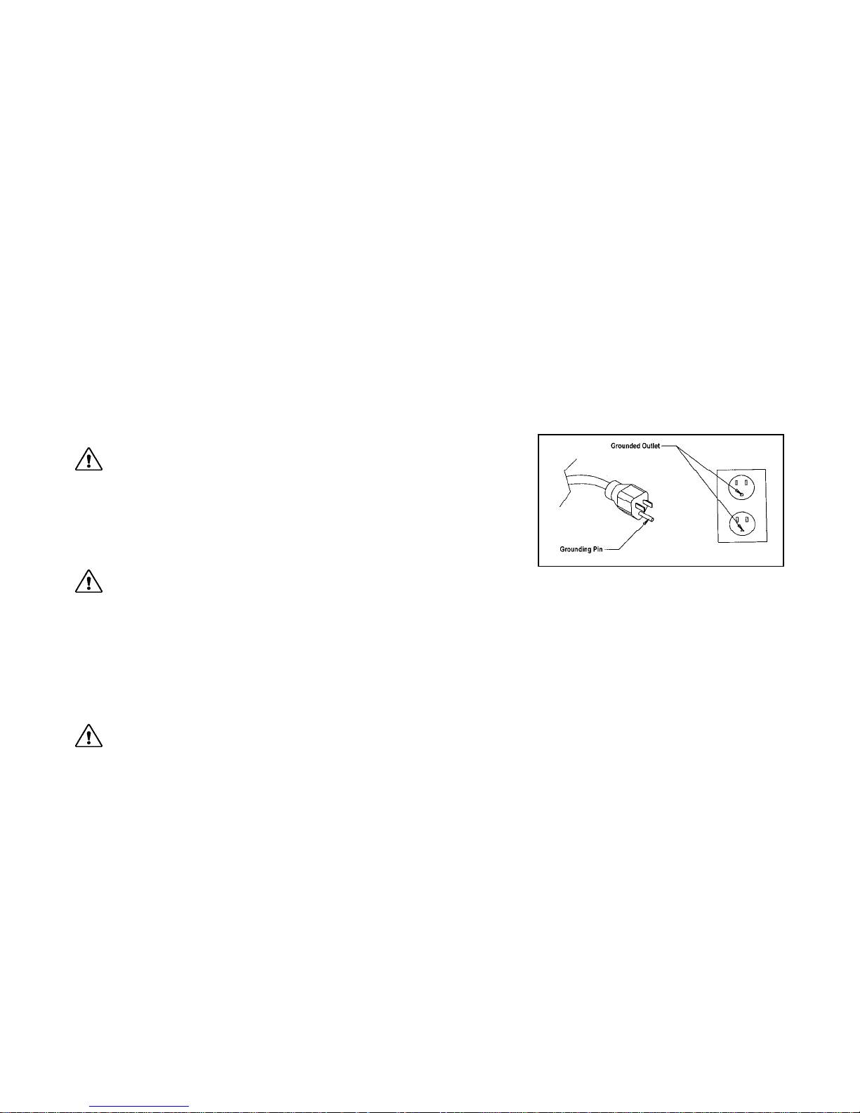
Grounding Instructions
DANGER: This product must be properly grounded. If it should malfunction or
become inoperable, grounding provides a path of least resistance for electric current to
reduce the risk of electric shock. This product is equipped with a cord having an
equipment-grounding conductor and a grounding plug. The plug must be plugged into
an appropriate outlet that is properly installed and grounded in accordance with all local
codes and ordinances. See example to the right.
WARNING: Improper connection of the equipment grounding-conductor can result in a risk of electrical shock. Check with a
qualified electrician or serviceman if you are in doubt as to whether the product is properly grounded. Do not modify the plug provided with
the product. If it will not fit the outlet, have a proper outlet installed by a qualified electrician. This product is rated for more than 15
amperes and is for use on a circuit having a nominal rating of 120 volts. It is factory equipped with a specific electric cord and plug to
permit connection to a proper electric circuit. Make sure that the product is connected to an outlet having the same configuration as the
plug. No adapter should be used with this product. Attempting to bypass it with an adapter or in any way defeating its purpose can
result in a serious shock hazard.
As a safety precaution, unplug the treadmill during electrical storms or if the treadmill will not be in use for periods greater than one week.
CAUTION: If you need to use an extension cord it must be a 14 gauge, three wire cord, no longer than 12 feet.
6
ASSEMBLY INSTRUCTIONS (cont’d)
Step One:
1-1.Carefully lower the handlebar
b on to its mounting brackets
c as shown in the figure. The mounting brackets c must slide
HARDWARE NEEDED
inside the handle bar
1-2. With the handle bar in place LOOSELY install eight 3/8-16 x 3/4“
button head screws
uprights as shown. The following must be done in the order it is
written. Tighten the screws labeled ‘A’ and then ‘B’.
b.
d with 3/8” washers e into both handlebar
1
4
3
A
B
3/8"- 16 x 3/4" (8 pcs)
3/8" SAE Black washer (8 pcs)
B
A
2
7
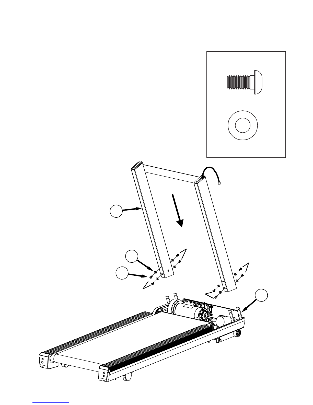
ASSEMBLY INSTRUCTIONS (cont’d)
CAUTION: Make sure the treadmill is NOT plugged into the electrical outlet until assembly is competed.
Step Two:
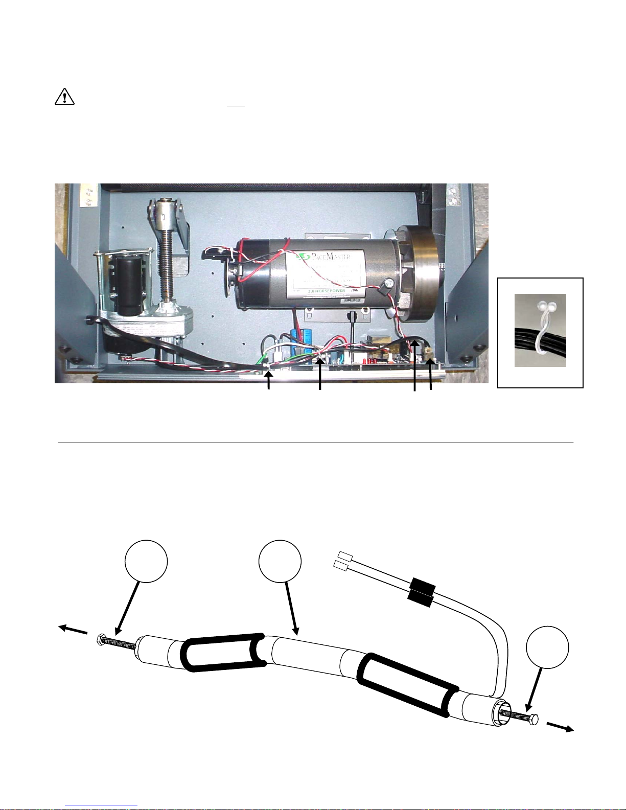
With the handlebar bolted in place, plug the black wire harness ‘A’ into the socket ‘B’ on the power supply board. Twist open the purse
lock clip at ‘C’, insert the wire harness ‘A’, confirm the wire harness is positioned as shown at point ‘B’ and twist close the purse lock clip.
Follow the same procedure for purse lock clip ‘D’.
Purse Lock Clip
Step Three:
3-1. Remove the Hex bolts
aside.
10 9
D C A B
k from both ends of ergo bar j. Set
Shown Closed
10
8

ASSEMBLY INSTRUCTIONS (cont’d)
Step Four:
4-1. Loosely attach left panel support tube
‘A’ and ‘C’, ¼-20 x 1 ¾” Hex Bolts
the upright
4-2. Loosely attach right panel support tube
‘B’, ¼-20 x 1 ¾” Hex Bolt(6) and ¼” washer
b. Do not tighten yet.
g and ¼” washers h to
b. Do not tighten yet.
4-3. Place the ergo bar
and
i as shown in FIG. 2.Make sure the pin on the left panel
support tube
ergo bar
tighten yet.
4-4. Loosely install Bolt ‘D’ a ¼-20 x 1 ¾” Hex Bolt
both CHR ground terminals, and then a ¼ “washer
tighten yet.
4-5. Proceed to tighten the ergo bar hex bolts
remaining four bolts, starting with ‘A’ and ending with ‘D’.
Note: Hold on to the CHR ground terminals so they do not twist
around the bolt when tightening.
Pin
f is in the notch of the ergo bar. Loosely attach
j with the two Hex bolts k from Step 3. Do not
j between the panel support tubes f
f by installing bolts
i by installing bolt
h to the upright
g through
h. Do not
k and then the
6
7
10
ACA
5
9
HARDWARE NEEDED
1/4"-20 x 1.75" Hex Head bolt (4 pcs)
1/4" washer (4 pcs)
CHR ground
terminals
D
B
8
1
9

ASSEMBLY INSTRUCTIONS (cont’d)
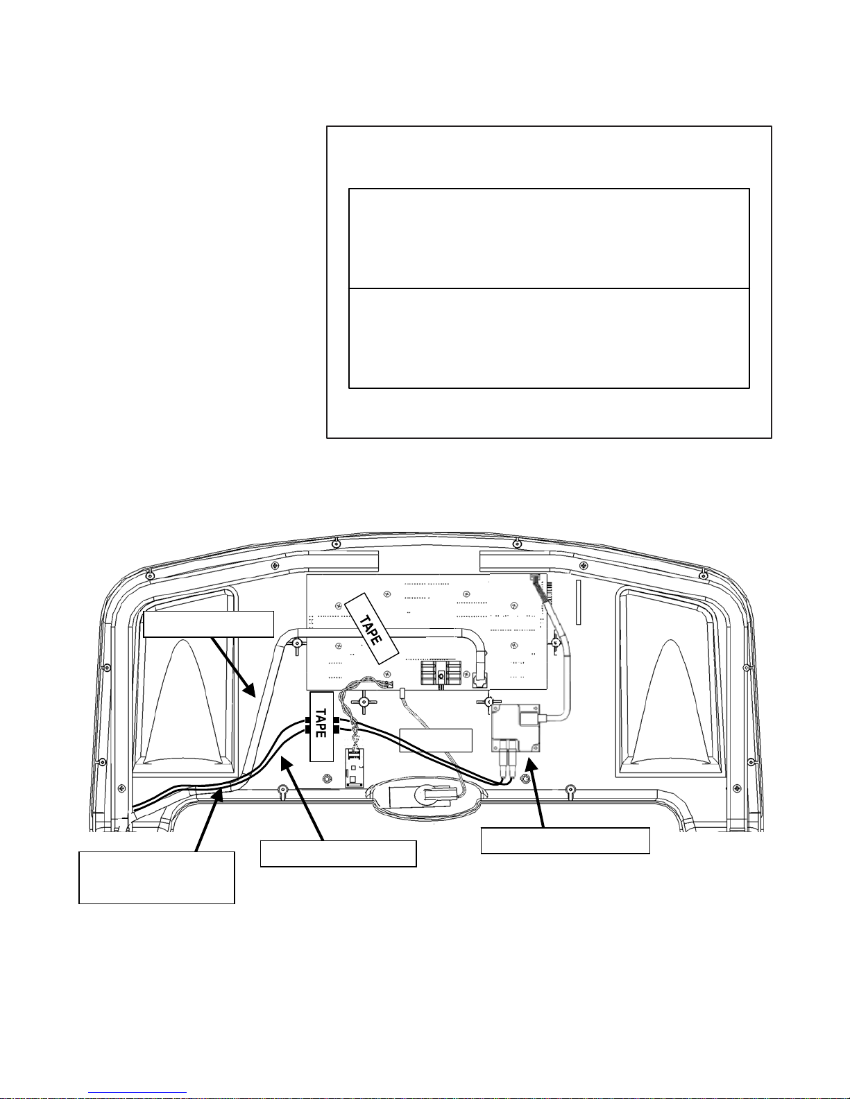
Step Five:
5-1. Route wire harness over the top of the right panel
support tube
as shown in the image below.
5-2.Route the Contact HR wires in front of the cross brace.
5-3. Lower control panel
Assembly with four #8 x 1.5” pan head screws tubes
labeled ‘A’ and then proceed to ‘B’.
Note: Make sure you do not pinch the wire harness.
f and rest in front of the cross brace
l onto the panel support tubes f and i.
m. Start with the screws
5
A
B
12
Contact HR Wires
HARDWARE NEEDED
#8 x 1.5" Pan Head (4 pcs)
11
8
B
Wire Harness
10
ASSEMBLY INSTRUCTIONS (cont’d)
Step Six:
5-1. Route the wire harness as shown
below. Plug in the harness into the display
board. Pull the wire harness taut then apply
one piece of tape exactly as shown.
5-2. Route the Contact heart rate wires as
shown below. Plug the CHR wires to CHR
module. Place a piece of tape directly over
the blocks in the wires exactly as shown.
Note: Make sure wires are inside panel
HARDWARE NEEDED
T
APE
TAPE
2 pieces of tape with backing
Wire Harness
Make sure wires are
inside panel
Contact HR Wires
Contact HR Module
11
ASSEMBLY INSTRUCTIONS (cont’d)
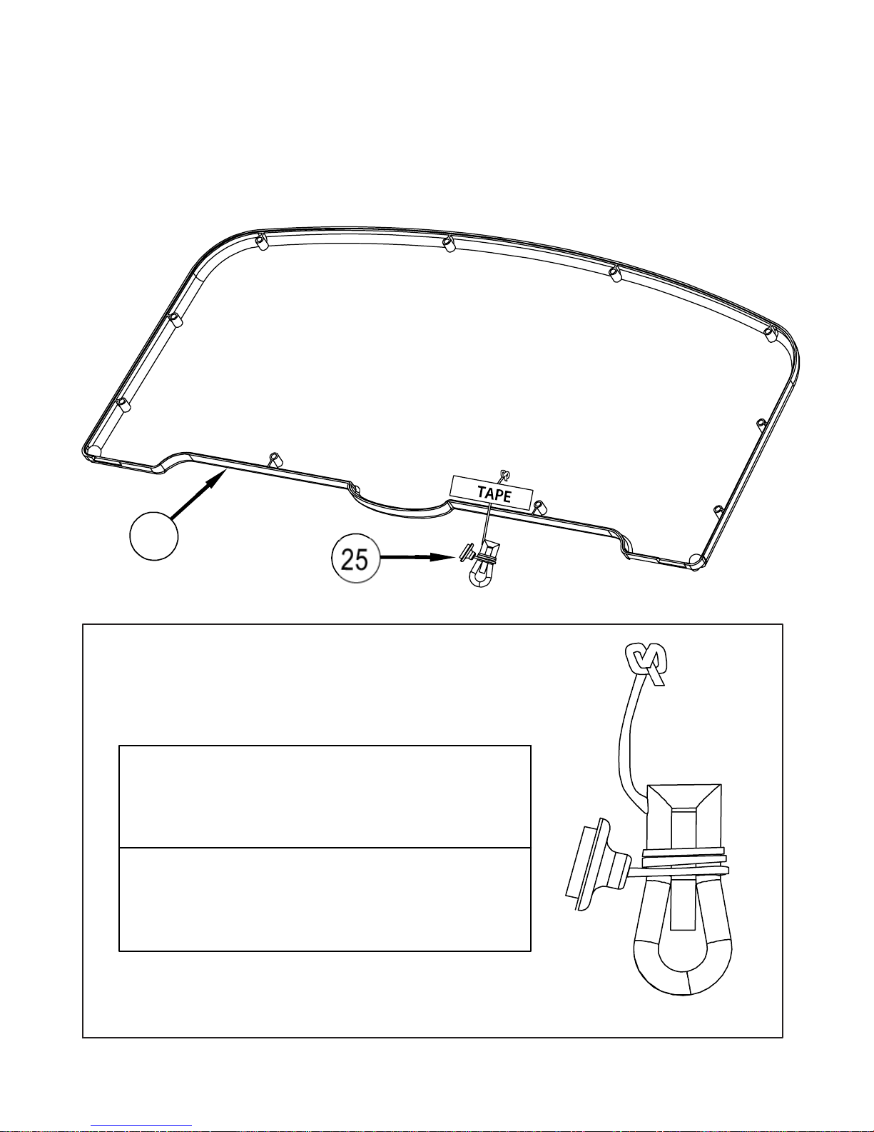
Step Seven:
Tape the magnetic safety key z to the control panel back n exactly as shown.
Note: You will have 1 extra piece of tape.
13
HARDWARE NEEDED
T
APE
TAPE
2 pieces of tape with backing
Magnetic Safety Key (1)
12
 Loading...