

Pacemaker 34 SPEED GRAPHIC, 45 SPEED GRAPHIC, 23 SPEED GRAPHIC, 45 CROWN GRAPHIC, 23 CROWN GRAPHIC Instruction And Reference Manual
...
SPEED
GRAPHIC
AND
CROWN
GRAPHIC
"
45
"
"
34
"
"23
"
. .
INSTRUCTION
AND
REFERENCE
MANUAL
I
mportant
Features.
Opening the Camera
Focusing
Infinity Stops
Focusing Scales
Rangefinder
Ground Glass
Viewfinders
Tubular
Open
Finder
.
TA
BLE
OF CONTENTS
The
Adj listable
Handle
Holding Camera ....................... .
Body Release ..................... .
Shutter
Selector Slide
Camera
Shutters
Focal
Plane
GRAPHEX
and
GRAPHEX
(X)
Flash
Supermatic
and
Supermatic
(X)
Correct Exposure
Stopping Motion
Depth
of Field
Front
Movements.
Lenses and Lensboards
Coated Lenses
Telephoto Lenses .
Long Bellows Extension .
..
.... .
....... .
Double Extension
(Close-up Photography)
Wide
Angle Lens (Drop Bed)
Film
and
Plate
Attachments .............. .
Film
Pack
Adapter
Sheet
Film
Holders
.
Fitting
Holders to
the
Camera
.
Tripod
Socket
Closing the Camera
Care
and
Servicing .
Handle
Your Camera Carefully
..
Emergency Attention
Technical
and
Service Departments
.......
...
....
. .
1
3
3
5
6
7
9
10
10
11
12
12
13
13
18
21
25
26
28
29
31
32
33
34
35
36
37
38
38
39
39
40
40
40
41
42
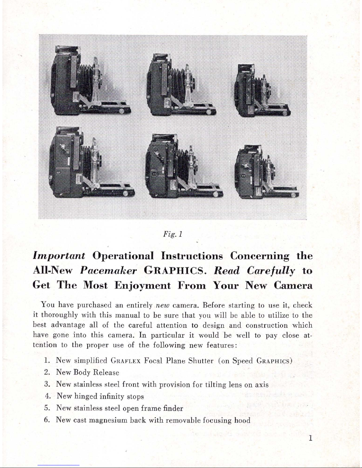
Fig. 1
Important
Operational
Instructions
Concerning
the
All-New
Pacemaker
GRAPHICS.
Read
Carefully
to
Get
The
Most
Enjoyment
From
Your
New
Camera
You have
pur
chased
an
entirely
new camera . Before
starting
to use it, check
it thoroughly with this
manual
to
be sure that
you will be able to utilize to
the
best
advantage all of
the
careful
attention
to
design a
nd
construction
which
have gone in
to
this camera.
In
par
ticul
ar
it
would
be
well
to
pay
close at-
tention
to
the
proper
use of
the
following new fea
tur
es:
1.
New simplified
GRAFLEX
Focal Plane
Shutter
(on Speed
GRAPHICS)
2. New Body Release
3. New stainless steel
front
with provision
for
tilting
lens on axis
4. New hinged infinity stops
5. New stainless steel open
frame
finder
6. New cast magnesium
back
with removable focusing hood
1
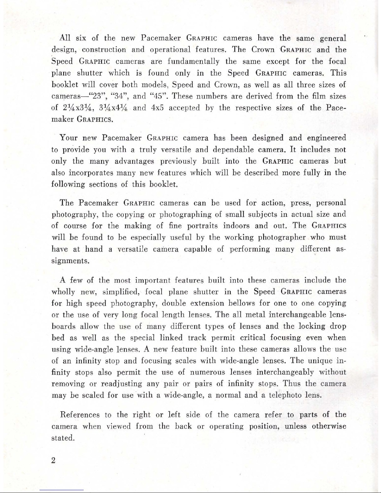
All six of
the
new
Pacemaker
GRAPHIC
cameras have the same general
design, construction
and
operational features.
The
Crown
GRAPHIC
and
the
Speed
GRAPHIC
cameras are fundamentally the same except for
the
focal
plane
shutter
which is found only
in
the Speed
GRAPHIC
cameras.
This
booklet will cover both models, Speed
and
Crown, as well as all
three
sizes of
cameras- "23", "34",
and
"45". These numbers
are
derived from
the
film sizes
of 2
'\4x3
'\4
, 3'\4x4
'\4
and 4.x5
accepted by the respective sizes of
the
Pace-
maker
GRAPHICS.
Your new
Pacemaker
GRAPHIC
camera has been designed
and
engineered
to provide you with a truly versatile and dependable camera.
It
includes not
only
the
many advantages previously
built
into
the
GRAPHIC
cameras
but
also incorporates many new features which will be described more fully
in
the
following sections of this booklet.
The
Pacemaker
GRAPHIC
cameras
can
be used
for
action, press, personal
photography, the copying or photographing of small subjects
in
actual size and
of course for the
making
of fine portraits indoors
and
out.
The
GRAPHICS
will
be
found to be especially useful by the working photographer who must
have
at
hand
a versatile camera
capable
of performing many different as·
signments.
A few of the most
important
features
built
into these cameras include the
wholly new, simplified, focal plane
shutter
in
the Speed
GRAPHIC
cameras
for high speed photography, double extension bellows for one to one copying
or
the
use of very long focal
length
lenses.
The
all metal interchangeable lens·
boards
allow
the
use of many different types of lenses
and
the
locking drop
bed as well as the special
linked
track
permit
critical focusing even when
using
wide·angle lenses. A new feature
built
into these cameras allows
the
use
of
an
infinity stop
and
focusing scales with wide-angle lenses.
The
unique
in-
finity stops also
permit
the
use of numerous lenses interchangeably without
removing
or
readjusting
any
pair
or pairs of infinity stops.
Thu
s the camera
may be scaled for use
with
a wide-angle, a normal
and
a telephoto lens.
References to the
right
or
left
side of the camera
refer
to
parts
of
the
camera
when viewed from the
back
or
operating
position, unless otherwise
stated.
2
Opening
The
Camera
With
the
camera
firmly supported by the left
hand
press the small release
button
at
the
upp
er left corner of the front of
the
camera
body.
The
kickout
spring
will
then
push
the
bed forward slightly
so
that
it
may be grasped
and
pulled downward
to
the
full locked position.
It
is not recommended
that
it
be
allowed
to
drop down with a snap.
The
front
standard
lock which is
in
the
form of a single finger
pull
should
then be swung directly forward unlocking the front
standard
and
allowing
it
to
be moved forward over the sliding
track
out
against the two infinity stops. *
In
order
to keep
both
sides of the
front
standard
firmly against the infinity stops
when locking
the
front s
tandard
grasp
the
lock
and
the
side of the front
standard
between th e
thumb
and
the
forefinger, pushing the lock to the
right
or
left
until
it
begins
to
tighten.
It
is not necessary to
turn
this lock all of
the way around
but
merely until
it
begins to tighten in which . position the
front
s:andard
will be held firmly on the sliding
track
by means of two flat plates
forced upward against the
track
itself.
Th
e camera is
then
ready for focusing upon infinity or nearby distances by
means of
either
of the two focusing knobs located
on
the
right
and
left
sides
of the
camera
bed
.
'To close the camera,
FIRST
rack
the
track
all
the
way
back into the camera
body.
Then
unlo'ck
the
front
standard
by
~winging
the finger
pull
forward. Move
the entire front
standard
back
into
the camera
body
as
far
as
possible and
lock
it
in place. Depress
the
two braces on
either
side of the bed
and
push
it
upward
until
it
snaps
securely into place.
Infinity
Stops
The
infinity stops fitted
to
the new
GRAPHIC
cameras
represent
several
advancements in design.
Of principle
interest
is the hinged member. As the
camera
was delive
red
to you, the infinity stops were undoubtedly in the raised
position. Now with the finger move
them
sideward
and
downward.
(Figure
2) .
It
will
then
be possible to pull
the
front
standard
forward as far as possible,
even out to
th
e full extension of
the
track. As shown in
Figure
15
two or even
more sets of infinity stops
and
appropriate foc
using scales may thus b
e.
used
with the
Pacemaker
GRAPHIC
cameras.
':'Note:
The
stops are actually constant reference points
and
the lens must be
focused
on
infinity by use of the focusing scale, the ground glass, or accessory
coupled rangefinder.
3
4
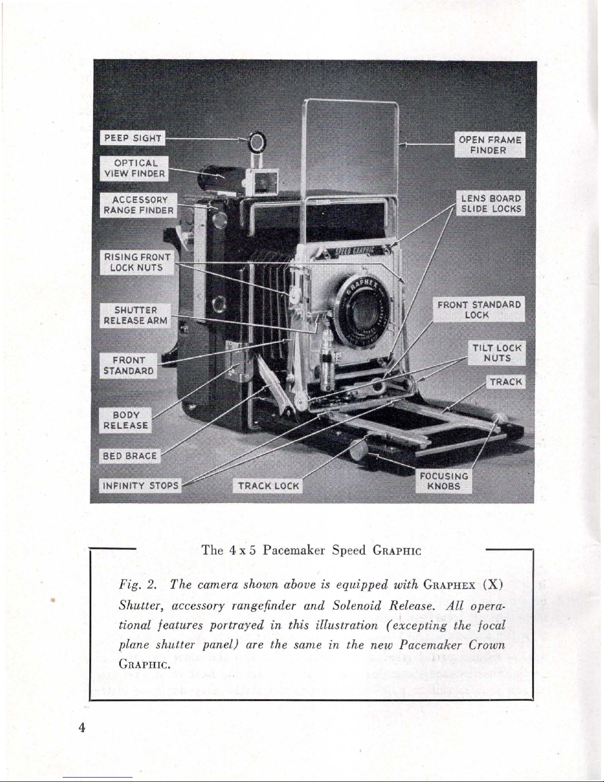
The 4 x 5 Pacemaker Speed
GRAPHIC
Fig.
2.
The camera shown above is equipped with
GRAPHEX
(X)
Shutter, accessory rangefinder and Solenoid Release.
All
opera·
tional features portrayed in this illustration
(e~cepting
the focal
plane shuuer panel) are the same in the new Pacemaker
Crown
GRAPHIC.
Occasion may arise as a result of accident, preference
in
method of use
or
any of a
number
of
other
reasons wherein
it
may be desired to
check
the
sharpness of the image carefully
on
the
ground
glass focusing screen even
though the
camera
may be
equipped
with focusing scales
calibrated
for
the
le
ns
in
use. These have all been
taken
into consideration
in
your new Pace-
maker
GRAPHIC
and
in
order to allow this careful check to
be
made without
the
necessity of moving the infinity stops they have
been
set
back
slightly from
what has been known as the
infinity position.
Thus
they may be said to be
"constant
reference"
instead of "infinity stops" of
the
usual type. As a result,
when the cam e
ra
is opened,
it
will be necessary to
rack
the
sliding
track
l:!ack
only
until
the two lines
indicating
the
infinity position on the focusing scales are
properly aligned with each other.
It
should be noted
that
in
order
to focus
the
lens
on
any
subject
at
a distance of more
than 4 or
6 feet when
the
bed
is
opened,
it
is necessary to move
the
sliding
track
backward,
so
that
this new
convenience will
require
little, if any, change
in
the accustomed
manner
of
preparing
the
camera
for
picture
making.
Of course, if
it
is desired to be able to move the front
standard
out
directly
to
what is known
as
the infinity position, these infinity stops may
be
moved
forward
as
desired.
This
is best accomplished only by a competent
camera
serviceman with
proper
equipment
for
squaring
the
front
standard,
relocating
and
relocking the infinity stops.
Foc
using
With
the
camera
bed
in
the
horizontal position
and
the
front
standard
locked
against the infinity stops, the sliding track may be
racked
forward or
back-
ward by means of either of the two knobs
at
the sides of the bed. Focusing
may be accomplished through the use of the focusing scale on the
bed
of
the
camera, an accessory coupled rangefinder, or by checking
the
sharpness of
the image
on
the
ground
glass focusing screen
at
the
back
of the camera. Only
the
latter
also
permits
checking for composition
and
depth
of field.
This
method will be more fully discussed
in
succeeding sections of this booklet.
Focusi
ng
Scales
The
focusing scales on the
GHAPHIC
cameras
are
of the modified Vernier
type with one
part
carried
on
the
camera
bed
and
the
other
on the sliding
track.
The
distances indicated are measured from the
back
of the
camera
to
the subject.
It
will be noted
that
both
of the scales
carry
duplicate distance
5

Fig.
3.
Modified Vernier Focusing
Scales
markings for the
greater
distances.
To use one of these settings,
turn
the
focusing knob
until
the
lines corre-
sponding
to
the desired distance
on
both
parts
of the focusing scale lie
directly opposite each other.
For
closer distances, the
pointer
at
the
front of
the
movable scale should be
placed directly opposite
the
line
in-
dicating the desired distance on the
stationary scale.
This
type of scale
is easier
and
quicker
to
read
than
the full Vernier or a
standard
type scale with a single movable index line.
The
lens of your
camera
has been supplied with
the
focusing scale calibrated
especially for it. To use this scale with any
other
lens, even of
the
same make,
speed
and
rated focal length, may result in out-of·focus pictures.
When
several lenses are to be used interchangeably on the camera, new in-
finity stops
and
Vernier scales
can
be fitted to
the
camera
bed. However,
the
proper
scaling of a l
ens
requires special
equipment
and
it
is best done only
at
one of the authorized
GRAFLEX
Service Departments.
At
the
right
front corner of the camera bed will be found a t
rack
lock in
the
form of a lever on
the
larger
GRAPHIC
cameras. Because of space limitations
in
the
GRAPHIC
"23"
cameras, there is a small set screw which may
be
adjusted
to
provide desired tension of the focusing track.
The
lever of
the
larger
cameras may be pulled outward
in
order
to produce desired tension on
the track.
If
pulled firmly around as far as possible,
it
will lock the
track
so
tbat
it
cannot
be moved accidentally. Remember
that
this must be unlocked
before attempting to
turn
the focusing knob since otherwise the bed mechanism
is
like
ly
to
be
damaged.
Rangefinder
If
the camera is fitted with a coupled rangefinder,
it
will not
be
necessary to
refer to
the
focusing scale
or
to
the
ground glass.
The
rangefinder will be of
6

the coincidental type. By looking through the window
at
the
rear
of
the
range finder
it
will be possible to see two distinct areas one lying within the
other. As the lens is focused
in
the normal manner, the rangefinder mechanism
will be operated
in
such a way as to cause the centrally located image to move
vertically. When the image
in
this
area
exactly coincides with the image
in
the
larger
area,
the
range
finder will be
in
correct
adjustment
for
that
subject
or
any
other
subject
matter
at
an
equal di stance from the camera.
If
the lens
on the camera is the one for which
the
rangefinder was originally adjusted,
it
will then be
in
focus
and
the exposure may be
made
with full assurance
that
the image will be critically sharp in the finished picture .
Ground
Glass F
ocusin
g
All
GRAPHI
C came
ras
are equipped
with
a ground glass focusing panel
at
the
back
of the camera.
In
the
GRAFLEX
back
this is
in
the form of a separate
removable
GRAFLEX
focusing panel, now supplied as a
standard
part
of the
camera.
In
the
GRAPHIC
back
this focusing panel will
be
found permanently
attached
by means of springs
at
the top
and
bottom.
The
ground
glass is mad e accessible by pressing inward on the small
latch
at
th e
back
which will allow the four·sided all· metal viewing hood
to
spring
open.
If
it
is desired to examine the
~
orners
or sides of the
ground
glass area
directly
with'
or
without the aid of a magnifying glass
the
viewing hood may
be removed easily by pressing outward
on
either of the two clips or springs
at
Fig.
4.
Viewing hood may
be
closed
with one hand.
Fig.
5.
Four sided all·metal removab!e
viewing hood.
7
the sides of the panel.
It
will be found easier to remove this viewing hood if
it
is
in
the open position
rather
than
closed .
In
order
to see
the
image
on
the
ground
glass focusing screen,
it
will be necessary to open both
the
front
and
focal plane shutters by setting them to the T
and
0 positions as directed
in
the
sections devoted to those shutters.
To close
the
viewing hood press inward with
the
thumb
and
the
forefinger
on
the
two lower side members
and
upward
on
the long lower section. Move
this all of
the
way
upward
into the
back
of the
camera
and then fold the top
door down unti l
it
latches. See
Figure
4.
In
the event
that
the
top door and its
attached
wings
spring
free, fold
the
lower flap all of the way up, swing the wings in against the top door
and
pull
it
down to latch. Upon release, the hood will
spring
open properly.
The
ground glass focusing screen will make
it
possible to
check
the
sharp-
ness of
the
image by moving the lens forward
or
backward by means of the
focusing knob on
the
bed
of the camera. Closing the
diaphragm
from the full
open position will also
make
it
possible
to
determine the
depth
of field which
will be included
in
the finished picture.
After
ground
glass focusing has
been
accomplished, lock the sliding
track
with the
track
lock mentioned before.
Remember
to close
and
cock the
shutter
which is to be used for
the
making
of
the
picture before
inserting
the film
attachment
into the camera.
Vi
ew
find
ers
Composition of
the
subject
matter may be accomplished by
anyone
of
three
different methods with
the
GRAPHIC
cameras.
The
ground
glass focusing screen
has already been discussed.
Your
Pacemaker
GRAPHIC
has two types of viewfinders,
either
of which
may be used when
it
is
inconvenient to
refer
to the
ground
glass.
Viewfinders
in
general should not
be
relied upon to give
an
exceedingly
accurate indication of the
amount
of
subject
matter
to be secured
on
the
negative, since the
amount
of subj
ect
matter
which will be seen depends largely
upon the position
at
which
the
obs erver holds his eye- a
factor
which varies
considerably between individuals
and
is greatly influenced by whether
or
not
the
user wears glasses.
The
optical viewfinder is often preferred in
order
to
define the limits of the field since this finder may
be
fitted with masks of
different sizes. However,
many
photographers
prefer
the
open framefinder for
all types of photography .
rather
than
merely for action photography. Both
finders are used
to
best advantage when the eye is held as close
as
possible to
the
rear
element.
8
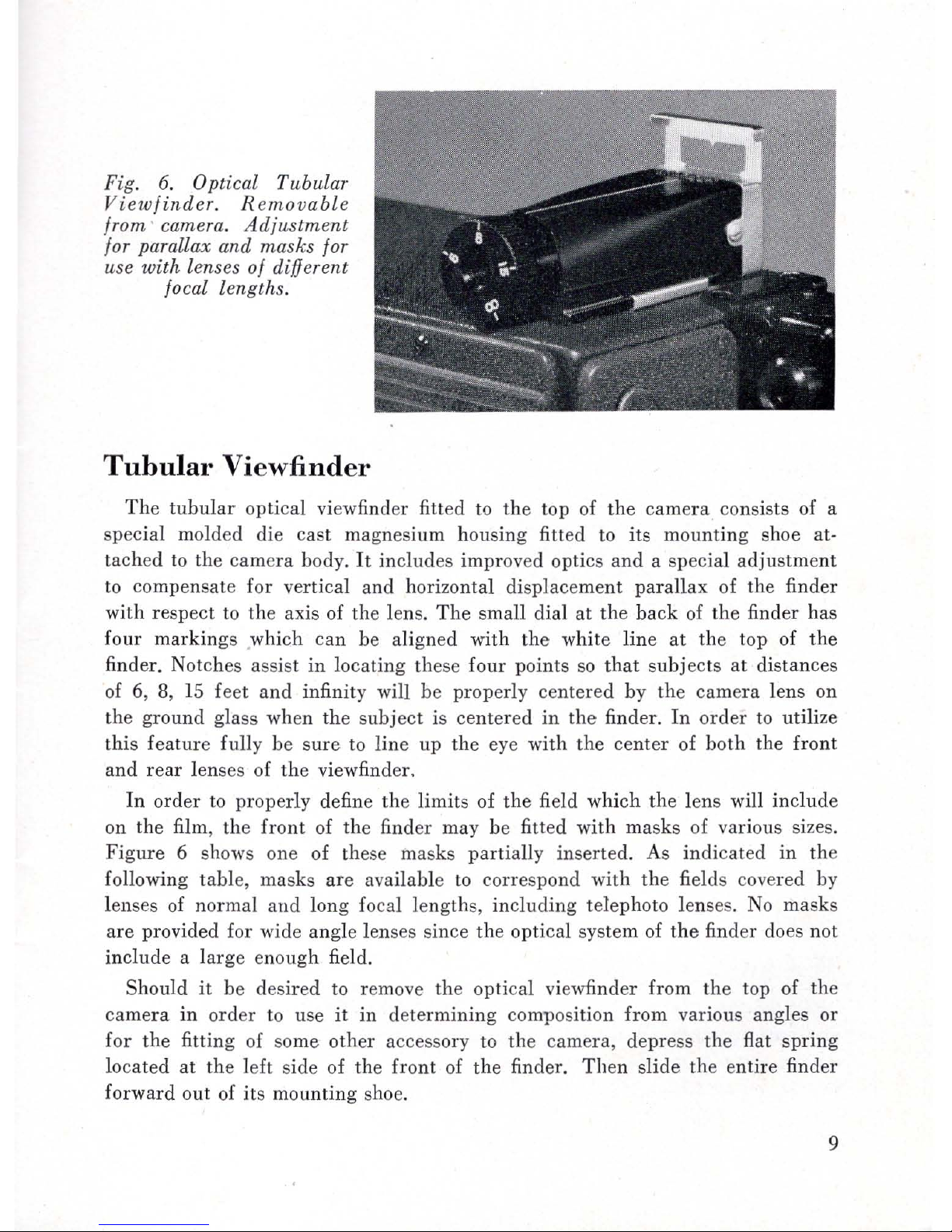
Fig.
6.
Optical Tubular
Viewfinder.
Removable
from ' camera.
Adjustment
for parallax
and
masks for
use
with
lenses
of
different
focal lengths.
Tubular Vi ewfinder
The
tubular
optical viewfinder fitted to
the
top of
the
camera
consists of a
special molded die cast magnesium housing fitted
to
its mounting shoe at-
taclled
to
the camera body.
It
includes improved optics and a special
adjustment
to
compensate for vertical and horizontal displacement
parallax
of the finder
with respect
to
the axis of the lens.
The
small dial
at
the
back
of the finder has
four
markings
.which
can
be aligned with
the
white line
at
the top of
the
finder. Notches assist
in
locating these
four
points
so
that
subjects
at
distances
of 6, 8,
15
feet
and
infinity will be properly centered by the
camera
lens
on
the ground glass when
the
subject
is centered
in
the
finder.
In
order
to utilize
this feature fully be
sure
to
line
up
the
eye
with
the
center
of
both
the front
and
rear
lenses of the viewfinder.
In
order
to
properly define the limits of
the
field which
the
lens will include
on the film, the
front
of the finder may
be
fitted with masks of various sizes.
Figure
6 shows one of these masks partially inserted. As indicated in the
following table, masks
are
available
to
correspond with the fields covered by
lenses
of
normal
and
long focal lengths,
including
telephoto lenses.
No
masks
are provided for wide angle lenses since
the
optical system of
the
finder does not
include a
large
enough field.
Should
it
be
desired to remove the optical viewfinder from
the
top of the
camera
in
order
to use
it
in
determining composition from various angles or
for
the fitting of some other accessory
to
the
camera, depress the flat
spring
located
at
the
left side of the front of
the
finder.
Then
slide the entire finder
forward out of its mounting shoe.
9
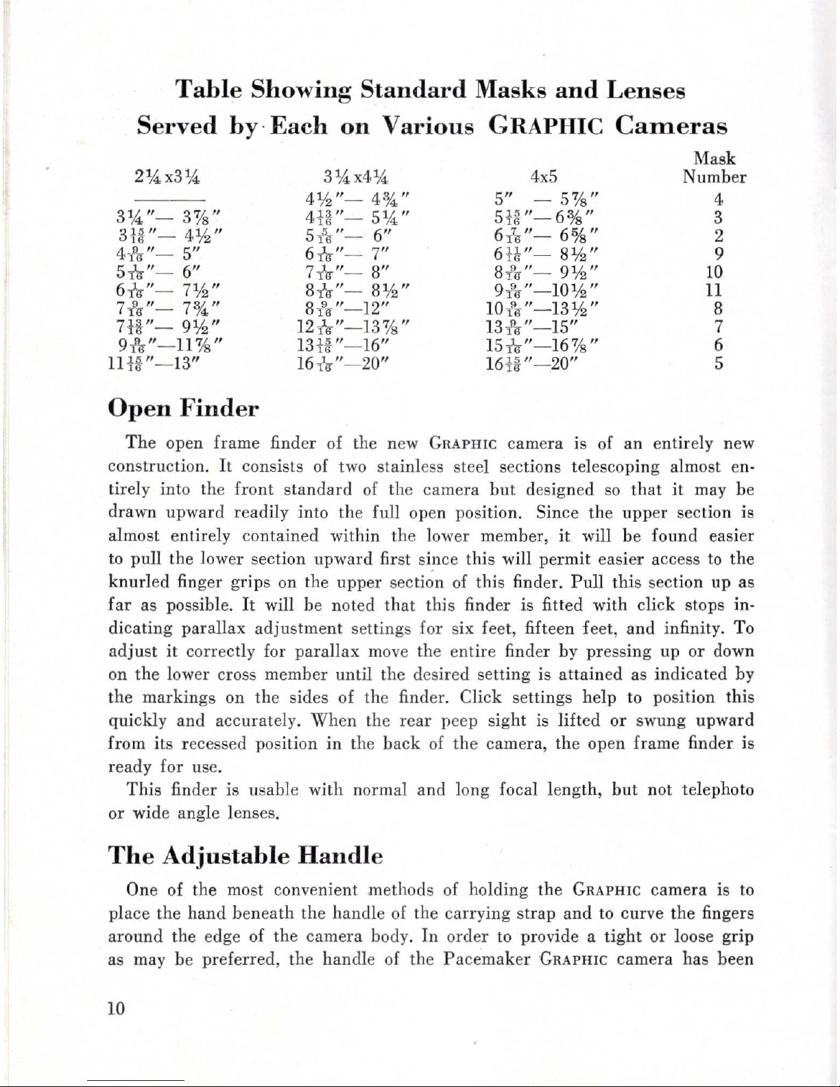
Table
Showing
Standard Masks
and
Lenses
Served
by·
Each
on
Various
GRAPHIC
CaIIleras
314 "- 3'%"
3U"-
4112"
4!lr"-
5"
5nr"
- 6"
6nr"- 7¥2"
7*
"-
7%"
7U
"-
9¥2"
9* "- 11'%"
1
HI/-"-
13"
Open
Finder
4¥2"-
4%"
4U"
- 5
1
4"
5i'\,"-
6"
6nr"-
7"
7nr"- 8"
8nr"- 8¥2"
8* "- 12"
12nr"
- 13,%"
13
U "- 16"
16
,10
"- 20"
4x5
5"
- 5'%"
5W '- 6o/s"
6
in-
"-
6%"
6U
"-
8¥2"
8
1'6
"- 9¥2"
9
!6
"-
10
¥2"
10
/6"-13¥2"
13
1'lr
"- 15"
15 nr"-16'%"
16
U "- 20"
Mask
Number
4
3
2
9
10
11
8
7
6
5
Th
e open frame finder of the new
GRAPHIC
camera is of
an
entirely new
construction.
It
consists of two
sta
inless steel sections telescoping almost en-
tirely into the
front
standard
of
the camera
but
designed
so
that
it
may be
drawn
upward
readily into the full open position. Since the
upper
section is
almost entirely contained within the lower member,
it
will be found easier
to
pull
the lower section upward first since this will
permit
easier access
to
the
knurled
finger grips on th e upper
secti~n
of this finder.
Pull
thi
s section up as
far
as possible.
It
will be noted
that
this
finder is fitted with click stops in-
dicating parallax
adjustment
se tting s for six feet, fifteen feet,
and
infinity. To
adjust
it
correctly for
parallax
move the entire finder by
pressing
up
or
down
on the lower cross
member
until
the desired se
tting
is
attained
as indicated by
the
markings
on the sides of the finde
r.
Click settings help to position this
quickly
and
accurate
ly.
Wh
en the rear peep sight is lifted
or
swung upward
from its recesse d position
in the
back
of th e camera, the open frame finder is
ready for use.
This
finder is usable with normal
and
long focal
length,
but
not telep hoto
or wide angle lenses_
The
Adjustable
Handl
e
One of the most convenient
methods
of holding
the
GRAPHIC
camera
is to
place the
hand beneath
the handle of the carry
ing
strap
and
to
curve the fingers
around
the edge of the
camera
bod
y.
In
order
to
provide a
tight
or loose grip
as may
be
preferred,
the
handl
e of th e Pace
maker
GRAPHIC
camera has been
10

Fig.
7.
Open frame finder.
Stainless steel telescoping
construction. Scale
read·
ings and
click
stops for
parallax correction.
Adjustable
Handle to
custom-fit hands
of
differ-
ent sizes.
designed to allow adjustment. A set of
three
snaps are provided and
if
you
desire a good
tight
handle
merely take up
on
the
snap buttons as provided.
Conversely to loosen
the
handle, extend
it
and
resnap
the
buttons together.
To unhook
the
entire
handle in order to provide access to the
tripod
socket
in
the
side of the camera, press
inward
on
the
spring
or
leaf of the snap
at
the base of
the
handle.
It
will
then
be possible to slip the entire clip off
the
lug
at
the bottom of the camera.
Holding
The
Camera
The
strap, on the side of the camera housing opposite to
that
on which the
focal-plane
shutter
controls are located, is designed for holding the outfit
in
use as well as for carrying
it
when not
in
its case. Holding this
in
the
left
hand
or slipping the
hand under
the
strap
and
gripping
the
edge of the body
(as you
prefer),
leaves the
right
hand
free for focusing,
shutter
operation,
and
film changing. Bracing
YOllr
arms against your body will increase the steadiness
with which you
can
hold the camera
and
therefore increase
the
sharpness of
your negatives, especially those exposed
at
the
slower
shutter
speeds.
11

Body
Release
All of the new
Pacemaker
GRAPHIC
cameras
have a
built-in
body
release
located
at
the
lower
right
corner
of
the
front of
the
camera.
This
is
an
entirely
new
feature
and
its convenient location makes
it
possible to
trip
either
the
front
or
focal
plane
shutter
by
squeezing
the
release lever
with
the
forefinger
while holding
the
camera
firmly
with
both
hands.
The
body release is
connected
to
the
front
shutter
by means of a special type
cable
which
employs
the
principle
of compression of
the
outer
stationary
mem-
ber
and
tension of the
inner
cable.
This
cable is concealed
beneath
the
bellows
by
straps
which control its folding when
the
camera
is closed, yet allow easy
transfer
of
pressure
from
the
body release to
the
shutter
release lever on
the
front of
the
camera,
whether
the
front
shutter
is
in
the
normal
position or
in
the
fully
extended
position such as is used
for
the
photographing
of small
sub-jects
in
actual
size.
Pr
essing
inward
on
the
body release activates
the
internal
part
of
the
cable
and
it
in
turn
pulls
downward on a
plunger
attached
to
the
front
standard
of
the
camera.
Attached
to
this
plunger
is a s
hutt
er
release
arm
which
in
turn
presses
against
the
release lever of
the
front
shutter
fitted
to
the
camera.
In
view of
the
fact
that
shutters
of different size
require
different
shutter
release
arms,
this
should
be
noted
when
changing
from one
lens
and
shutter
combina
-
tion to another. New
lensboard
kits
m;y
be
purchased
from
GRAFLEX
dealers.
Each
kit
includes a precision
cut
lensboard
for a specific lens
and
shutter,
the
appropriate
shutter
release
arm
for
the
plunger
on
the
front
standard,
as well as
the
necessary light-excluding felt
washer
for
the
locating
pin
of
the
shutter.
The
release
arms
are
held
in
place
on
the
plunger
by
means of a
sma
ll
set
screw
and
can
be
easily
and
quickly positioned
in
such
a way as to
insure
the
easy
and
accurate
tripping
of
the
front
shutter.
Shutter Selector Slide
The
selector slide
at
the
right
side of
the
focal
plane
shutter
mechanism
of
the
Speed
GRAPHIC
cameras
is provided
in
order
to allow
the
body release
to
operate
selectively
either
the
focal
plane
or
the
front shutt
er.
When
this
slide
is pressed
inward
and
pulled
down so
that
the
raised
portion
is opposite
the
word
FRONT,
the body release wi!]
trip
the
front
shutter.
Pressing
this
slide
inward
at
the
bottom
and
moving it up
until
the
raised
portion is opposite
the
word BACK will allow
the
body release to
operate
the
focal
plane
shutter.
When
the
slide is
pressed
inward
at
the bottom
and
moved all of the way
upward
to
12
 Loading...