

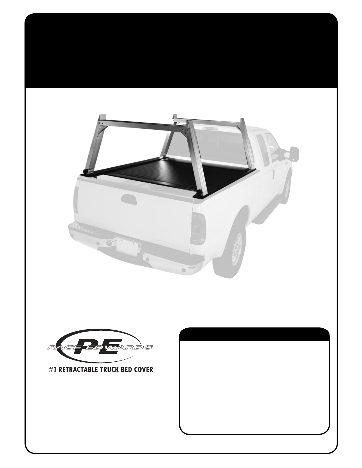
UTILITY RIG RACK
PACE EDWARDS RETRACTABLE HARD TRUCK BED COVER & UTILITY RACK SYSTEM
STANDARD INSTALLATION INSTRUCTIONS
IMPORTANT! The Pace Edwards truck bed cover and Explorer Series Rails
MUST be installed on the truck fi rst before attempting to install this rack system!
(800) 338-3697
www.paceedwards.com
Pace Edwards Company
2400 Commercial Blvd.
Centralia WA 98531
*Flip over for Contractor Rig Rack instructions
Tools Required for Assembly.........................................2
Before Y ou Start ...........................................................2
Utility Rack Illustration...................................................2
Packaging Contents .....................................................3
STEP 1: Install Side Stops ...........................................4
STEP 2: Assemble legs & gussets ..............................4
STEP 3: Assemble Crossmembers..............................4
STEP 4: Assemble Crossmembers, Legs & Braces.....5
STEP 5: Install Truss Mounts on Explrer Series Rails..5
STEP 6: Install Pickup Trusses on Truss mounts ........5
TABLE OF CONTENTS
Part #: UR-CR Rack-INSTALL 048
TOOLS REQUIRED FOR ASSEMBLY:
9/16” wrench or socket
1/2” open ended wrench
Flat clean surface (such as card board paper or plastic
Silicone sealant (if necessary)
BEFORE YOU START:
Read the instructions carefully before you start. These instructions are written for one-person installation. We
have noted where briefl y having an extra person’s assistance can make installation easier. If you have questions
regarding the installation please call our Technical Support Line at (800) 338-3697.
IMPORTANT! The Pace Edwards truck bed cover and Explorer Series Rails
MUST be installed on the truck fi rst before attempting to install this rack system!
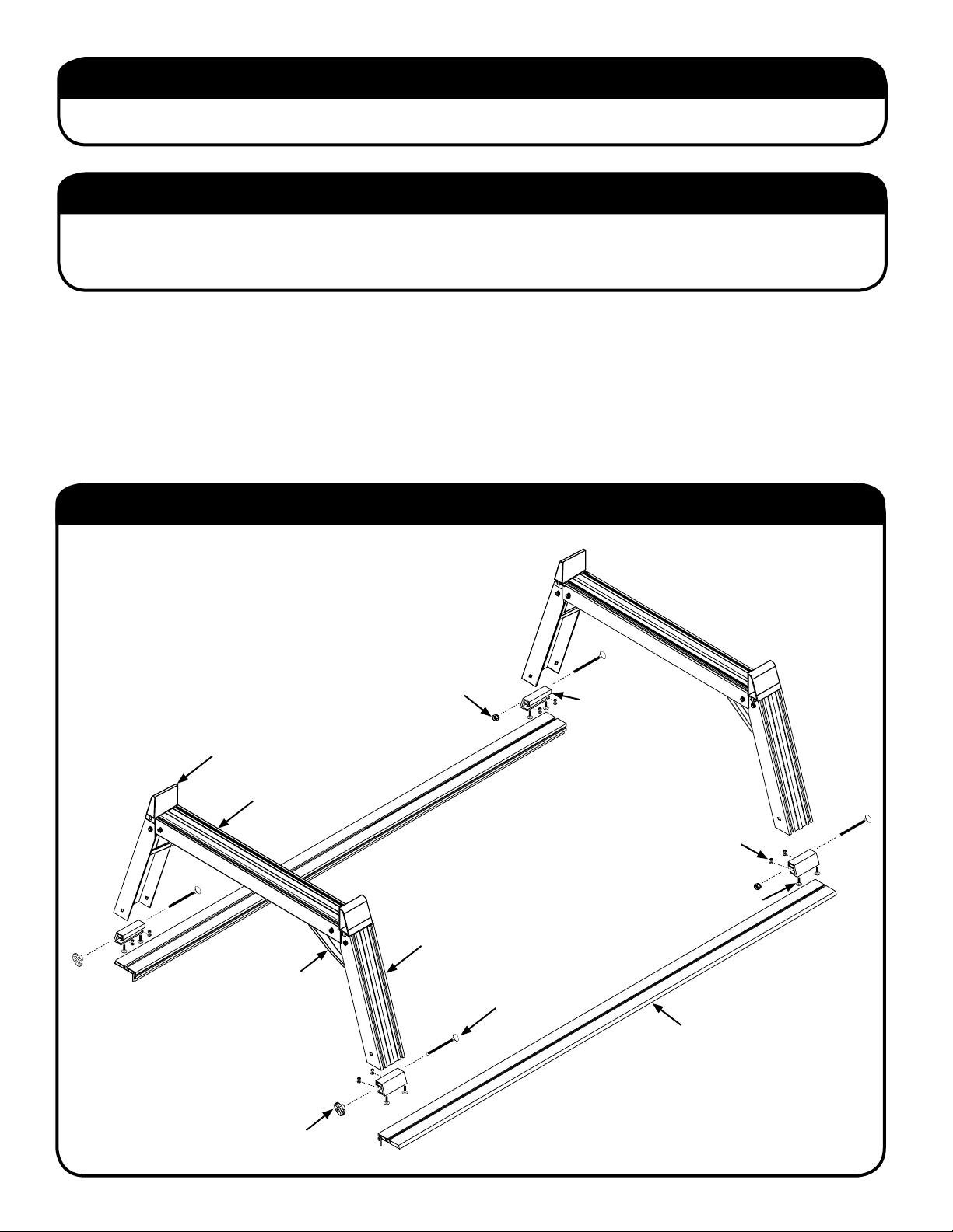
UTILITY RIG RACK ILLUSTRATION:
SIDE STOPS (x4)
TRUSS CROSSMEMBER (x2)
3/8” LOCK NUT (x12)
5/16” STAINLESS LOCK
WASHERS & NUTS (x16)
1” CARRIAGE BOLTS (x16)
LEGS (x4)
BRACES (x 4)
5” CARRIAGE BOLTS (x 12)
EXPLORER SERIES RAIL
(ORDERED SEPARATELY
WITH TRUCK BED COVER)
3/8” KNOB (x2)
2
UTILITY RIG RACK
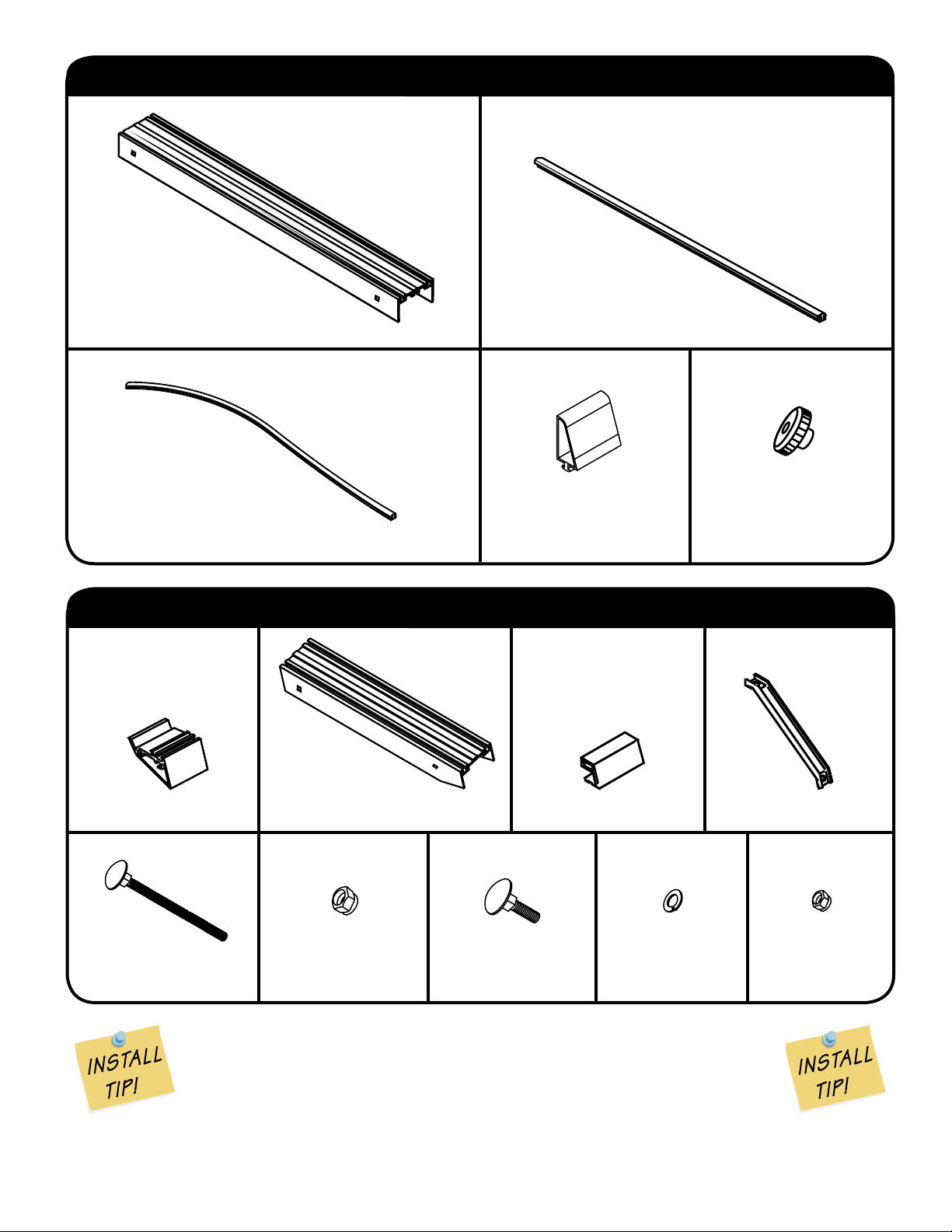
UTILITY RIG CROSSMEMBER BOX CONTENTS:
TRUSS CROSSMEMBER (x2) REAR CROSSMEMBER TRUSS
PLASTIC LOW FRICTION INSERT (x1)
CROSSMEMBER TRUSS RUBBER
ANTI-WEAR INSERTS (x2)
UTILITY RIG LEG BOX CONTENTS:
TRUSS MOUNTS (x4)
3/8” KNOB (x2)SIDE STOPS (x4)
5” CARRIAGE BOLTS (x 12)
A General Note on Assembly:
These parts have been precision cut to tolerances as close as one thousandth of an
inch. Some fi ts are designed to be press fi ts, others are designed to be sliding fi ts; but
nowhere should the use of great force be required for assembly. As with any piece
of machined equipment, if a part is not fi tting as it should, don’t use excessive force,
identify the problem and correct it. An initial misalignment of two parts can cause a burr
on one of them and make smooth assembly diffi cult.
INSTALLATION INSTRUCTIONS
LEGS (x4) BRACES (x 4)GUSSETS (x 4)
3/8” LOCK NUT (x12)
1” CARRIAGE
BOLTS (x16)
TRUSS MOUNTS (x4)
5/16” STAINLESS
LOCK WASHERS
(x16)
5/16” STAINLESS
LOCK NUTS (x16)
3
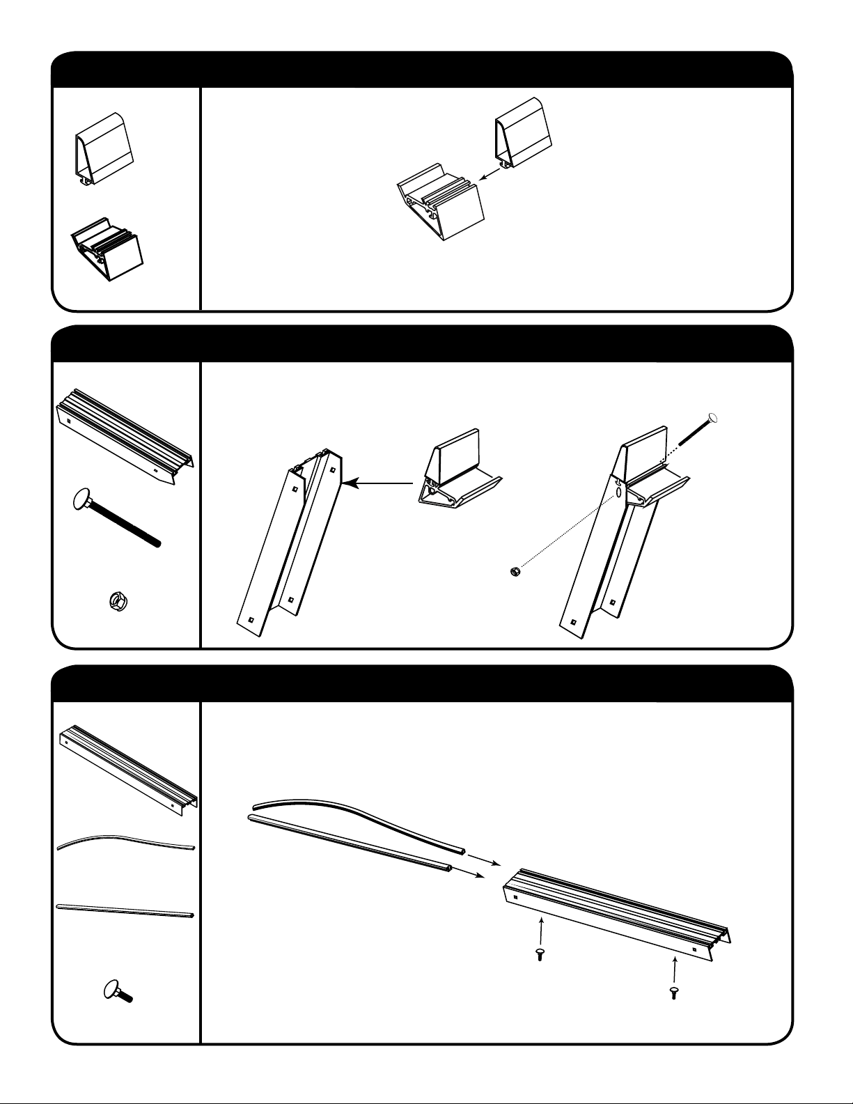
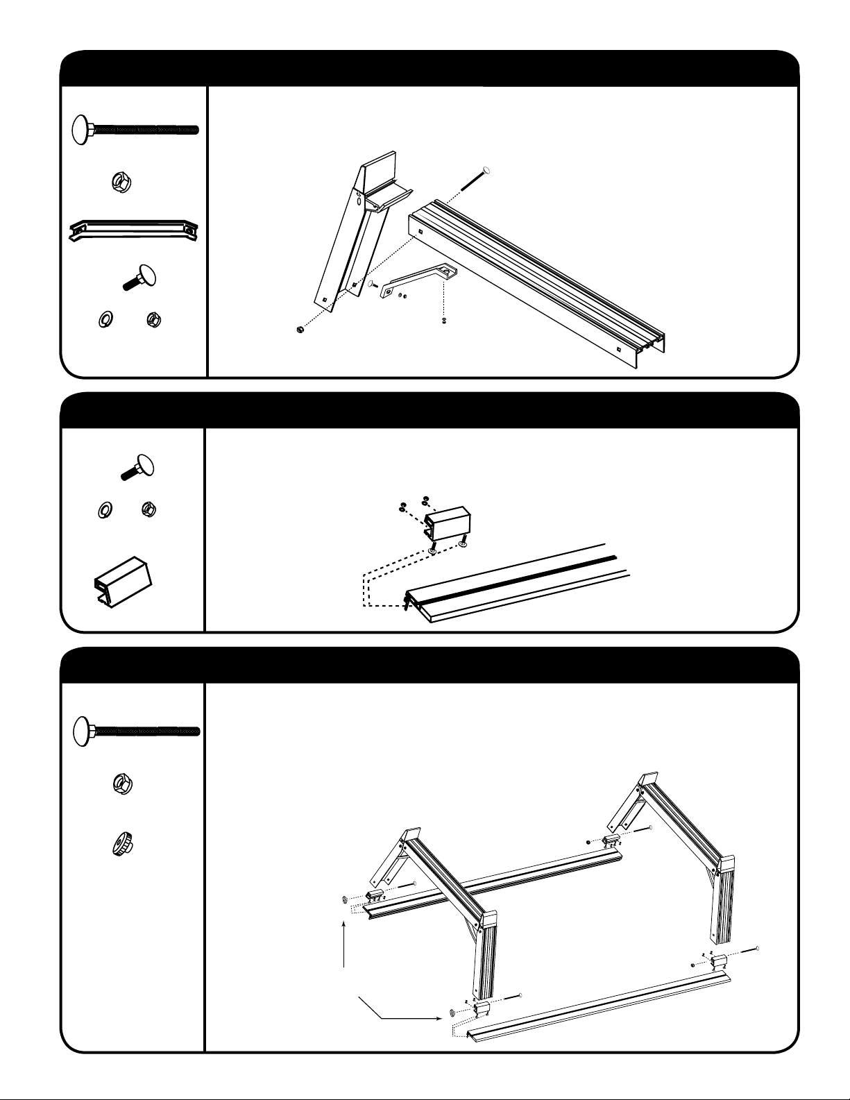
STEP 1: INSTALL SIDE STOPS
HARDWARE USED:
SIDE STOPS x 4
NOTE: To prevent Side Stops from the possibility of rattling, inject some silicone sealant
GUSSET x 4
into the T-slot of the gusset before inserting Side Stop.
STEP 2: ASSEMBLE LEGS & GUSSETS
HARDWARE USED:
Install gussets into legs as shown until holes align, then slide the 5” carriage bolts through
the holes. Install the 3/8” lock nuts on the 5” carriage bolts and tighten with a 9/16” wrench
until they bear lightly (do not tighten yet) on the aluminum surface.
LEGS x 4
5” CARRIAGE BOLTS x 4
3/8” LOCK NUTS x 4
STEP 3: ASSEMBLE CROSSMEMBERS
HARDWARE USED:
Slide a rubber anti-wear insert into the forward T -slot of each crossmember and slide a plastic
low-friction insert into the REAR T-slot on the REAR crossmember. Slide 2 small carriage
bolts (to be used for braces) into the T-slot on the underside of each crossmember.
TRUSS CROSSMEMBER (x2)
CROSSMEMBER
TRUSS RUBBER ANTIWEAR INSERTS (x2)
REAR CROSSMEMBER
TRUSS PLASTIC LOW
FRICTION INSERT (x1)
1” CARRIAGE BOLTS x 4
4
Plastic insert goes in REAR
T-slot of REAR truss ONLY!
UTILITY RIG RACK
STEP 4: ASSEMBLE CROSSMEMBERS, LEGS & BRACES
HARDWARE USED:
Install crossmember on gusset as shown, and fasten loosely with 5” long carriage bolts and
3/8” locknuts. Slide a small carriage bolt into the inside T -slot of the leg and install the brace
between the leg and the crossmember using nuts and lock washers.
5” CARRIAGE BOLTS (x 4)
3/8” LOCK NUT (x 4)
BRACES (x 4)
1” CARRIAGE BOLTS (x 4)
5/16” STAINLESS LOCK
WASHERS & NUTS (x 8)
STEP 5: INSTALL TRUSS MOUNTS ON EXPLORER SERIES RAILS
HARDWARE USED:
1” CARRIAGE BOLTS (x 8)
Slide two 1” carriage bolts into the upper T-slots on each end of both Rails. Place a truss
mount on each of the bolt pairs (truss mount should be leaning inward as shown), positioning
the mounts 1/8” in from the ends of the rails. Install lock washers and nuts and tighten with
a 1/2” open end wrench.
5/16” STAINLESS LOCK
WASHERS & NUTS (x 8)
TRUSS MOUNTS (x4)
STEP 6: INSTALL PICKUP TRUSSES ON TRUSS MOUNTS
HARDWARE USED:
5” CARRIAGE BOLTS (x 4)
3/8” LOCK NUT (x 2)
3/8” KNOB (x2)
Lower the truss onto the truss mounts and slide the 5” long carriage bolts through the leg and
mount. Install nuts and tighten with a 9/16” wrench until they bear LIGHTL Y on the aluminum
surface. Make sure that the truss is centered on the rails and that the visible joint between the
leg and crossmember is as tight as possible, then tighten all 5” carriage bolts fi rmly. Note that
the truss mount has an elongated hole for side-to-side adjustment of the truss legs. Tighten
the nuts and knobs that secure the braces
INSTALLATION INSTRUCTIONS
UTILITY RIGS USE 3/8”
KNOBS ON REAR TRUSS
5

THIS PAGE HAS BEEN INTENTIONALLY LEFT BLANK

THIS PAGE HAS BEEN INTENTIONALLY LEFT BLANK

2
INSTALLATION INSTRUCTIONS
height within the side rails of the rack
No warranty is made about the suitability of this product for any purpose other than securing ladders. Keep cargo
away from sharp or hot surfaces. CHECK TENSION FREQUENTLY - STRAPS STRETCH AND LOADS SETTLE.
washers are securely in place and that parts move freely . Keep at least 2 wraps of strap around mandrel. Keep strap
Inspect strap and winch assembly before each use and replace if worn or damaged. Make sure that the cotter pin and
It is a recommended industry standard that the working load not exceed 1/3 of the rated capacity or 400 lbs.
The Work Winch has a rated capacity of 1200 lbs. This is the load the complete assembly will withstand before failure.
REMEMBER TO CHECK STRAP TENSION FREQUENTLY BECAUSE STRAPS STRETCH AND LOADS SETTLE.
and tighten using the handle. Do not over tighten as the handle has been designed to slip on the hex if it is over-stressed.
engage the hook on the underside of the 2 1/2” tall lip of the crossmember. Take up the slack by rotating the hand wheel
To secure a load, let the handle hang freely, lift the pawl and pull out enough strap to go over the load. For pickup trucks,
OPERATION & CAUTIONS
STRAP AROUND MANDREL
KEEP AT LEAST 2 WRAPS OF
END THRU MANDREL
INSERT 6” OF STRAP
RIG GUSSET
CONTRACTOR
ORIENTATION
CORRECT STRAP
RIGHT HAND WINCH INSTALLATION
STRAP AROUND MANDREL
KEEP AT LEAST 2 WRAPS OF
END THRU MANDREL
INSERT 6” OF STRAP
RIG GUSSET
CONTRACTOR
ORIENTATION
CORRECT STRAP
LEFT HAND WINCH INSTALLATION
away from you. The hook end of the strap should come up on the outside of the coil from underneath.
careful attention to the orientation of both the pawl and the strap. The pawl looks like a dolphin and its nose faces
Work Winches can be installed form either the left side or the right side of Contractor Rig gussets and brackets. Pay
STEP 3: INSTALLATION DETAIL & DRAWING

WORK WINCH
Suggested park position for handle
1
the pawl.
within it). If the pawl is installed correctly, this is the only direction you will be able to turn the winch without lifting
you (If the handle has been installed, disengage it from its upper position and let it hang freely so the hex can rotate
Insert 6” of the strap end into the slot in the mandrel and wind in a direction so that the top of the spool comes toward
STEP 2: INSTALL THE STRAP
If handle is to be kept on winch shaft, engage as shown to prevent swinging and wear
the lynch pin and lock it.
over the hex, install the smaller washer and then insert
accessible place. If it is to be installed, place the handle
The handle can be installed or left in a tool box or other
with a pair of pliers.
onto the winch take-up wheel and spread the cotter pin
the other large washer and then the cotter pin. Hold
Slide the winch the rest of the way into the hole. Install
winch shaft.
pin through the pawl and into the small hole above the
its nose is facing away from you and slide the 2” clevis
Orient the pawl (which is shaped like a dolphin) so that
halfway into the hole in the gusset.
Then install the PVC bearing, then insert the assembly
Slide 1 of the 2 large washers onto the winch shaft.
LYNCH PIN (x 4)
STEP 1: INSTALL WORK WINCH IN GUSSET
SMALL WASHER (x4)HANDLE (x4)LARGE WASHER (x8)PVC BEARING (x 4)
PAWL (x4)
CLEVIS PIN (x4)
STRAP (x4) COTTER PIN (x 4)WINCH SHAFT (x 4)
WORK WINCH BOX CONTENTS:
or it can be installed with the winch on the left and the handle on the right (a mirror image).
Winches are included with the Contractor Rig Rack and can be installed with the winch on the right and handle on the left
The Work Winch is installed on Contractor Rig rack after the entire rack has been assembled and installed. 4 Work
STANDARD INSTALLATION INSTRUCTIONS
™
INTEGRATED TIE-DOWN SYSTEM (INCLUDED WITH CONTRACTOR RIG RACK)
WORK WINCH

INSTALLATION INSTRUCTIONS 7
CROSSMEMBER
EXTENSION BEAM TAB FITS INSIDE
REAR FRONT
NUTS (x 8)
5/16” STAINLESS
on some models due to a tapering truck body.
WASHERS (x 8)
5/16” STAINLESS LOCK
experience some degree of effort installing the Extension Beam over the bolt on the front truss
Complete the installation of the Extension Beam (which was left loose). It is normal to
install lock washers & nuts and tighten.
are seated and install a 1” carriage bolt downward through each end of the crossmember, then
1” CARRIAGE BOLTS (x 8)
is helpful in crossmember assembly). Make sure the Extension Beam and the crossmember
tab of the Extension Beam inside the crossmember (lifting unbolted end of the Extension Beam
side of the truck, hand the correct end of the crossmember over (see drawing) and insert the
Install the rubber wear strip in the crossmember. With the aid of another person on the opposite
HARDWARE USED:
STEP 9: INSTALL CROSSMEMBER

CONTRACTOR RIG RACK 6
assemble the crossmember.
the forward end slightly off the front truss to
on the rear Truss only, as you will need to lift
side and loosely install a lock washer and nut
Set the other Extension Beam on the opposite
NUTS (x 8)
5/16” STAINLESS
these two Extension Beam mounting bolts.
Install lock washers and nuts and tighten
Truss.
WASHERS (x 8)
5/16” STAINLESS LOCK
of the beam with the rear surface of the rear
(notched end goes in front), aligning the end
Mount one Extension Beam on the Trusses
HARDWARE USED:
STEP 9: INSTALL EXTENSION BEAMS ON TRUSSES
DECAL
bubbles, creases etc.
with just as much “grip” as the dry method would but without the risk of misalignment,
positioned, force out excess water with fi ngers or a sponge. The decal will ultimately adhere
wet method allows you to slide the decal around to position it correctly. When correctly
Extension Beam and apply the decal centered between holes over the splice joint. This
DECALS (x2)
PARALLELOGRAM
of dish washing liquid to a glass of water, pull off the decal backing, wet the decal and the
can be installed dry, the “wet method” makes the job much easier. Just add 10 or 12 drops
(800)338-3697
Position the decal accurately so that it repeats the punched hole pattern. Although the decal
holes do!
HARDWARE USED: Important! There are left and right decals! Decal leans forward just like Extension Beam
STEP 8: INSTALL DECAL OVER SPLICE JOINTS
3/8” STAINLESS NUT (x4)
WASHERS (x8)
3/8” STAINLESS LOCK
WASHERS (x4)
3/8” STAINLESS FLAT
then tighten nuts. Repeat the procedure for the remaining Extension Beam.
the other hole, align Extension Beam halves so that the outside surfaces meet smoothly, and
then install a fl at washer, then lock washer, then nut, in that order. Repeat the procedure for
blocks align. Slide a 3/8” fl at washer on the 4” bolt and insert the bolt through the splice blocks,
end to end so that the welded-in splice blocks touch each other and the holes in the splice
Locate a matching pair of Extension Beams (all holes leaning the same way) and place them
Beams (ie. cardboard, paper, plastic).
You will need a smooth clean surface where you can bolt together the halves of the Extension
BOLTS (x 4)
4-3/8” STAINLESS
HARDWARE USED:
STEP 7: ASSEMBLE EXTENSION BEAM HALVES

5
INSTALLATION INSTRUCTIONS
that secure the braces
the nuts and knobs
of the truss legs. Tighten
for side-to-side adjustment
mount has an elongated hole
3/8” LOCK NUT (x 4)
bolts fi rmly. Note that the truss
is as tight as possible, then tighten all 5” carriage
rails and that the visible joint between the leg and crossmember
5” CARRIAGE BOLTS (x 4)
aluminum surface. Make sure that the truss is centered on the
tighten with a 9/16” wrench until they bear LIGHTLY on the
carriage bolts through the leg and mount. Install nuts and
Lower the truss onto the truss mounts and slide the 5” long
HARDWARE USED:
STEP 6: INSTALL PICKUP TRUSSES ON TRUSS MOUNTS
open end wrench.
lock washers and nuts and tighten with a 1/2”
mounts 1/8” in from the ends of the rails. Install
be leaning inward as shown), positioning the
on each of the bolt pairs (truss mount should
on each end of both Rails. Place a truss mount
TRUSS MOUNTS (x4)
Slide two 1” carriage bolts into the upper T-slots
using nuts and lock washers.
into the inside T-slot of the leg and install the brace between the leg and the crossmember
Slide 2 small carriage bolts into the T -slot at the bottom of the gusset and slide 1 carriage bolt
CROSSMEMBER ONL Y!
HANDLE & KNOB ON REAR
WASHERS & NUTS (x 8)
5/16” STAINLESS LOCK
1” CARRIAGE BOLTS (x 8)
HARDWARE USED:
STEP 5: INSTALL TRUSS MOUNTS ON EXPLORER SERIES RAILS
5/16” KNOB (x2)
HANDLES (x2)
3/8” ADJUSTABLE
WASHERS & NUTS (x 12)
5/16” STAINLESS LOCK
1” CARRIAGE BOLTS (x 12)
BRACES (x 4)
3/8” LOCK NUT (x 2)
crossmember.
5” CARRIAGE BOLTS (x 4)
provided in the crossmember box. Use the 5/16” knob to fasten the brace under the rear
3/8” locknuts. For the rear crossmember of Contractor Rigs use the 2 adjustable handles
Install crossmember on gusset as shown, and fasten loosely with 5” long carriage bolts and
HARDWARE USED:
STEP 4: ASSEMBLE CROSSMEMBERS, LEGS & BRACES

CONTRACTOR RIG RACK
4
1” CARRIAGE BOLTS x 4
T-slot of REAR truss ONLY!
Plastic insert goes in REAR
bolts (to be used for braces) into the T-slot on the underside of each crossmember.
low-friction insert into the REAR T-slot on the REAR crossmember. Slide 2 small carriage
Slide a rubber anti-wear insert into the forward T -slot of each crossmember and slide a plastic
FRICTION INSERT (x1)
TRUSS PLASTIC LOW
REAR CROSSMEMBER
WEAR INSERTS (x2)
TRUSS RUBBER ANTICROSSMEMBER
MEMBER (x2)
TRUSS CROSS-
HARDWARE USED:
STEP 3: ASSEMBLE CROSSMEMBERS
3/8” LOCK NUTS x 4
5” CARRIAGE BOLTS x 4
LEGS x 4
until they bear lightly (do not tighten yet) on the aluminum surface.
the holes. Install the 3/8” lock nuts on the 5” carriage bolts and tighten with a 9/16” wrench
Install gussets into legs as shown until holes align, then slide the 5” carriage bolts through
HARDWARE USED:
STEP 2: ASSEMBLE LEGS & GUSSETS
Slide 1” Carriage bolt into the T-slot of the gusset as shown above.
HEAVY GUSSETS x 4
1” CARRIAGE BOLTS x 4
HARDWARE USED:
STEP 1: INSTALL EXTENSION BEAM MOUNTING BOLTS

3
INSTALLATION INSTRUCTIONS
on one of them and make smooth assembly diffi cult.
identify the problem and correct it. An initial misalignment of two parts can cause a burr
of machined equipment, if a part is not fi tting as it should, don’t use excessive force,
nowhere should the use of great force be required for assembly. As with any piece
inch. Some fi ts are designed to be press fi ts, others are designed to be sliding fi ts; but
These parts have been precision cut to tolerances as close as one thousandth of an
A General Note on Assembly:
DECALS (x2)
PARALLELOGRAM
(800)338-3697
LOCK NUTS (x24)
5/16” STAINLESS
BRACES (x 4)
WASHERS (x24)
5/16” STAINLESS LOCK
TRUSS MOUNTS (x4)
WASHERS (x4)
3/8” STAINLESS LOCK
WASHERS (x8)
3/8” STAINLESS FLAT
1” CARRIAGE BOLTS (x24)3/8” LOCK NUT (x12)5” CARRIAGE BOLTS (x 12)
LEGS (x4)
(x4)
3/8” STAINLESS NUT
BOLTS (x 4)
4-3/8” STAINLESS
EXTENSION BEAM HALVES (x4)
CONTRACTOR RIG EXTENSION BEAM BOX CONTENTS:
HEAVY GUSSETS (x 4)
5/16” KNOB (x2)3/8” ADJUSTABLE
HANDLES (x2)
LOCK NUTS (x6)
5/16” STAINLESS
ANTI-WEAR INSERTS (x3)
CROSSMEMBER TRUSS RUBBER
EXT. BEAM CROSSMEMBER (x1)
LOCK WASHERS (x6)
5/16” STAINLESS
CONTRACTOR RIG LEG BOX CONTENTS:
BOLTS (x6)
1” CARRIAGE
PLASTIC LOW FRICTION INSERT (x1)
REAR CROSSMEMBER TRUSS
TRUSS CROSSMEMBER (x2)
CONTRACTOR RIG CROSSMEMBER BOX CONTENTS:

CONTRACTOR RIG RACK
COVER)
WITH TRUCK BED
SEPARATELY
RAIL (ORDERED
EXPLORER SERIES
2
INSTALLATION
RIG GUSSET & BRACE
DETAIL OF CONTRACTOR
LEGS (x4)
GUSSETS (x 4)
HEAVY
BRACES (x 4)
CROSSMEMBER (x2)
TRUSS
WEAR INSERT (x3)
RUBBER ANTI-
CROSSMEMBER (x1)
REAR FRONT
CROSSMEMBER
THIS TAB FITS INSIDE
EXT. BEAM
EXTENSION BEAMS (x4-HALFS)
MOUNTS (x4)
TRUSS
REAR T-SLOT (x1)
PLASTIC INSERT IN
LADDER GLIDE
UTILITY RIG RACK ILLUSTRATION:
MUST be installed on the truck fi rst before attempting to install this rack system!
IMPORTANT! The Pace Edwards truck bed cover and Explorer Series Rails
regarding the installation please call our Technical Support Line at (800) 338-3697.
have noted where briefl y having an extra person’s assistance can make installation easier. If you have questions
Read the instructions carefully before you start. These instructions are written for one-person installation. We
BEFORE YOU START:
Silicone sealant (if necessary)
Flat clean surface (such as card board paper or plastic
1/2” open ended wrench
9/16” wrench or socket
TOOLS REQUIRED FOR ASSEMBLY:

Part #: UR-CR Rack-INSTALL 048
WORK WINCH INSTRUCTIONS ..............................8-9
STEP 10: Install Crossmember ..............................................7
STEP 9: Install Extension Beams on Trusses.........................6
STEP 8: install decal over splice joint .....................................6
STEP 7: Assemble extension beam halves ............................6
STEP 6: Install Pickup Trusses on Truss mounts ...................5
STEP 5: Install Truss Mounts on Explrer Series Rails.............5
STEP 4: Assemble Crossmembers, Legs & Braces................5
STEP 3: Assemble Crossmembers.........................................4
STEP 2: Assemble legs & gussets .........................................4
STEP 1: Install Side Stops ......................................................4
Packaging Contents ................................................................3
Utility Rack Illustration..............................................................2
Before Y ou Start ......................................................................2
Tools Required for Assembly....................................................2
Centralia WA 98531
2400 Commercial Blvd.
Pace Edwards Company
www.paceedwards.com
(800) 338-3697
*Flip over for Utility Rig Rack instructions
TABLE OF CONTENTS
MUST be installed on the truck fi rst before attempting to install this rack system!
IMPORTANT! The Pace Edwards truck bed cover and Explorer Series Rails
STANDARD INSTALLATION INSTRUCTIONS
PACE EDWARDS RETRACTABLE HARD TRUCK BED COVER & UTILITY RACK SYSTEM
CONTRACTOR RIG RACK
 Loading...