

Pace Edwards Roll-Top-Cover Installation Instructions Manual
elpfu
RETRACTABLE HARD TONNEAU COVER
Roll-Top-Cover® shown on 2003
Chevrolet Silverado
Pace Edwards Company
2400 Commercial Blvd.
Centralia WA 98531
(800) 338-3697 toll free
(360) 736-9991 main
(360) 736-9992 fax
www.paceedwards.com
Part #: RT-INSTALL 123
Revised 12/03
INSTALLATION
INSTRUCTIONS
TABLE OF CONTENTS
Tools Required for Assembly (FIG. 1) ....................................2
Before You Start .....................................................................2
Drain Hole Locations (FIG. 2)..................................................2
Packaging Contents (FIG. 3) ..................................................2
Hardware Kit Supplied with Unit (FIG.4) .................................3
STEP 1: Remove Contents from Box ....................................3
STEP 2: Place Canister..........................................................3
STEP 3: Install Rails (FIG. 5a, 5b) .........................................3
STEP 4: Install Guide Strips...................................................4
STEP 5: Adjust Position of Canister (FIG. 6) .........................4
STEP 6: Install Lock Arm Assembly (FIG. 7a, 7b, 8) ..........4-5
STEP 7: Adjust Position of Guide Strips (FIG. 9)...................5
STEP 8: Adjust Lock Arm Assembly ......................................6
STEP 9: Install Drain Tubes...................................................6
STEP 10: Install Top Cover ................................................... 6
Warranty Statement.................................................................7
H
l Maintenance Hints ......................................................7
1
1
4
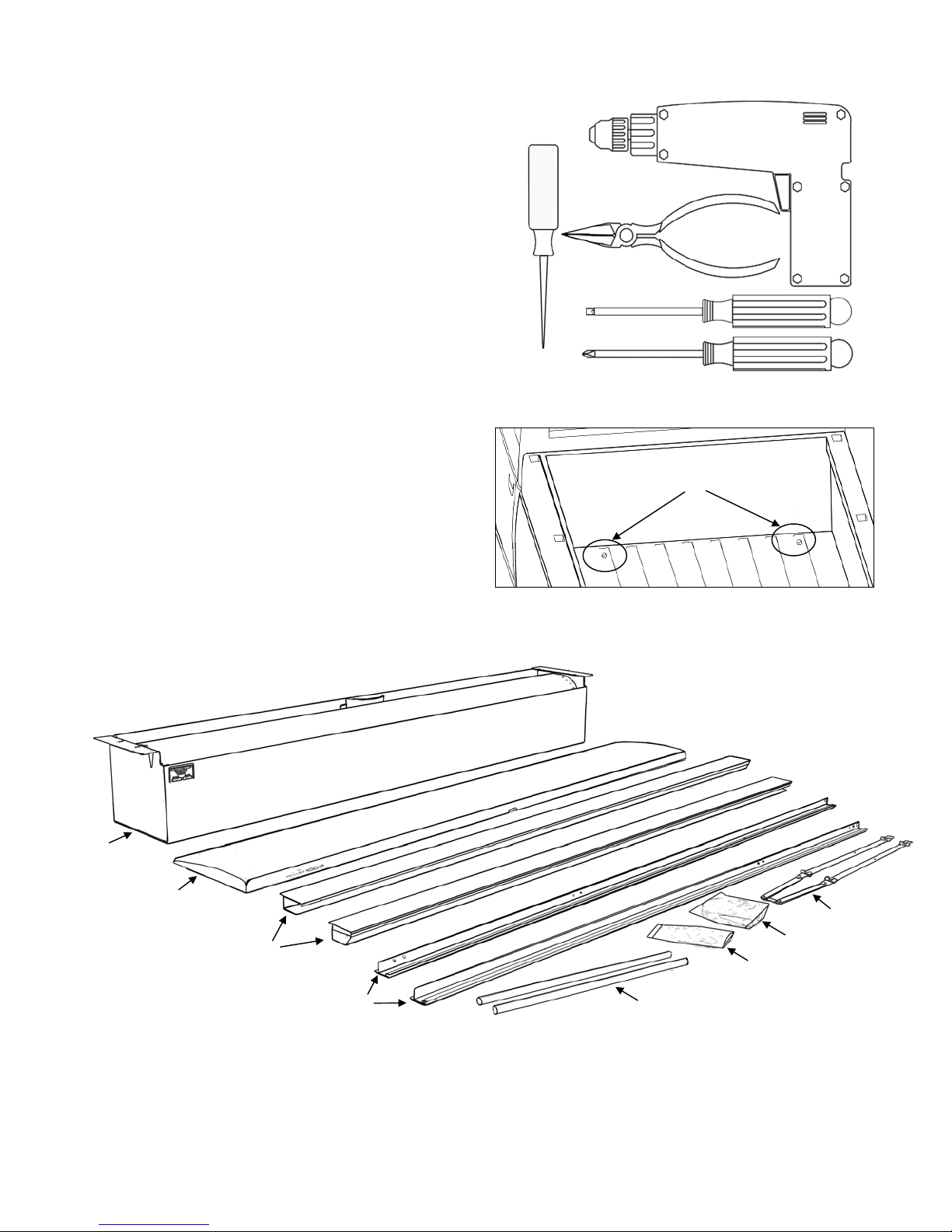
TOOLS REQUIRED FOR ASSEMBLY:
FIG. 1
Electric drill*
Phillips screwdriver
Slotted screwdriver (or
5
/16” & 1/4” nut drivers) and
Center punch*
Needle nose pliers
*If you purchased the clamp on rail option, no drilling or
punching will be required.
BEFORE YOU START:
Read the instructions carefully before you start. If you have
questions regarding the installation of your new Roll-Top-
®
Cover
retractable tonneau cover, please call our Technical
Support Line at (800) 338-3697 or visit our web site at
www.paceedwards.com.
DRAIN HOLE LOCATIONS:
The Roll-Top-Cover® is designed to carry rainwater from
the fabric cover into the canister and then out through
the drains. Most truck models have standard OE drain
holes or plastic/rubber access ports in the front of the
Drain Tube Holes
truck bed. Check to make sure your truck has the OE
drain holes so that drilling into the sheet metal is not
required. If drilling is necessary, be sure to check the
underside of the truck bed for the best location. The
holes should be located near the side and as far forward
as possible. Use a drill bit suitable for sheet metal (such
as a taper drill or step drill). Drill drain tube clearance
FIG. 2
holes at 5/8" (16mm). This will need to be done before
installing the cover.
PACKAGING CONTENTS:
FIG. 3
2 ROLL-TOP-COVER
2
8
7 6
CONTENTS IN CANISTER BOX
1. Canister Assembly
2. Top Cover Assembly
3. Lock Arm Assembly
4. Hardware Pack
5. Shim Pack
6. Drain Tubes
3
5
CONTENTS IN RAIL BOX
7. Guide Strips (left & right)
8. Rails (left & right)
®

HARDWARE KITS SUPPLIED WITH UNIT:
FIG. 4
STEP 1: REMOVE CONTENTS FROM BOX
Remove canister and top cover from the box. Perform a quick inventory to insure all parts are
there. (If any parts are missing call Pace Edwards Technical Support for replacement, (800)
338-3697.)
CAUTION! PERMANENT DAMAGE MAY BE CAUSED IF THE
HANDLE ASSEMBLY IS ALLOWED TO RETRACT INTO THE CANISTER WITHOUT
PROTECTION ON THE UNDERSIDE OF THE FABRIC PANEL!
STEP 2: PLACE CANISTER
Use a soft rag or some packing materials from the box to wedge between the fabric roll and
handle to temporarily keep the fabric roll from winding into the canister. Remove the screw
and metal clip holding the handle to the canister. Place the canister in the front of the truck
bed, cab side forward, in the position required for unrolling. Center side to side. Do not attach
STEP 3: INSTALL & FASTEN THE RAILS**
the canister yet.
** If you have purchase the optional Clamp Kit Assembly no drilling will be
required. Refer to the instructions provided with the Clamp kit.**
Remove the side rails and guide strips from their box. The side rails are marked “left” and
“right” (left is the driver’s side of the truck). With the tailgate closed, place the side rails in
position on the truck bed. (Figure 5a & 5b) Side rails have a rubber spacer on the end caps, at
the tailgate end, to establish the correct spacing to the tailgate (1/16”) and to prevent the
tailgate from striking the side rails when closing. Press the rail tightly against the closed
tailgate. Shims may be required to maintain a horizontal top surface on the rails. Peal and
stick the shims horizontally close to the rail mounting holes. Shims are provided in two
thicknesses. Shims may need to be stacked on each other to create the right thickness.
Repeat the same process on each side. Once rails are in the correct position mark the hole
locations through the side rails with a felt tip pen. Remove the side rails. Center punch and drill
with the drill bit provided. To make assembly easy pre-thread the holes with the #10 selftapping sheet metal screws provided. Replace the side rails on the truck bed and securely
tighten the screws at this time.
INSTALLATION INSTRUCTIONS 3
 Loading...