

Pace-Edwards LK370 User Manual
INSTALLATION INSTRUCTIONS
Ford F-150/250 Light Duty &
Super Crew - 1997 to 2010
Purple &
Gray wires
Green &
Blue wires
Long Wire
Harness
Short Wire
Harness
Wire
Ties
Wire
Taps
Ford Super Duty - 1999 to 2005
Part # LK370
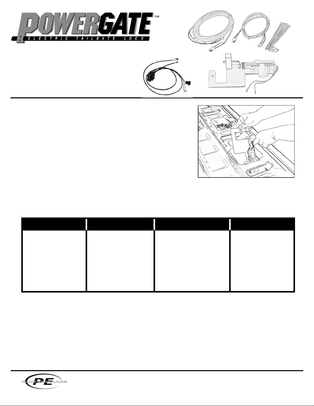
STEP 1: Install PowerGate™
Note: If your truck is equipped with an OEM manual door lock, install the PowerGate
with the OEM manual lock in the unlocked position.
With tailgate open, remove the screws from the tailgate access panel using a Torx
T-30 screwdriver. Remove the 10mm nut on the left side of the handle assembly.
In order to get the powergate in the correct position you will need to temporarily
remove the lock bar rod from the plastic rod retainer and move it aside. This will
make it possible to maneuver the powergate assembly underneath the bar. Once
the powergate is in place you can reconnect the lock bar rod into the rod retainer.
Install PowerGate lock through the tailgate opening and over stud on left side of
handle assembly. (see Fig. 1) Replace the 10mm nut and tighten. Slide the lock
bolt with your fi ngers to insure that there is no interference and that the bolt works
properly. Adjust if necessary.
STEP 2: Route the Wire Harness & Relay Loom Wires
Route the short wire harness through the drain hole in the bottom of tailgate and connect it to PowerGate. Plug the long wire
harness to the short wire harness. Route the long wire harness underneath the driver’s side of the truck to the fi rewall.
Using the Relay Loom on the drivers side of the engine compartment thread the purple and gray wire loom through the fi re wall of
the truck. (Try to follow OEM wire routes whenever possible.)
STEP 3: Locate and Connect Wires
2008-2010 F150/F250 Light
Duty & Supercrew
Route the wires through the
fi rewall on the drivers side.
Locate the blue w/ green
and gray w/ brown wires
inside the drivers side kick
panel. Install one blue wire
tap on the blue w/ green
stripe wire and one blue wire
tap on the gray w/ brown
stripe wire.
1997-2007 F150/250 Light
Duty & Supercrew
Run wires under the dash
across to the passengers’ side
of the truck carefully remove
the passengers’ side kickpanel to fi nd the wire harness
with the pink w/black wire and
the red w/orange wire. Install
one blue wire tap on the pink
w/black and one blue wire tap
on the red w/orange wire for
these trucks.
Relay
Loom
Red wire w/ fuse
holder &
black ground-wire
2004- 2005 Super Duty 1999- 2003 Super Duty
Run wires under the dash across
to the passengers’ side of the truck
carefully remove the passengers’
side sill plate near the base of the
seat belt to fi nd the wire harness
with the red w/ orange stripe and
pink w/ black stripe wires. Install
one blue wire tap on the red w/
orange stripe wire and one blue
wire tap on the pink w/ black
stripe wire.
Route the wires through the
fi rewall on the drivers side.
Locate the red w/ orange
stripe and pink w/ black
stripe wires under the dash
above the steering column.
Install one blue wire tap on
the red w/ orange stripe
wire and one blue wire tap
on the pink w/ black stripe
wire.
PowerGateTM
LK370 Unit
Fig. 1
Plug the purple and gray wires to the wire taps. Return to the engine compartment and plug the long wire harness from the
PowerGate unit to the Relay loom with the green and blue wires. (Testing will be done later to insure appropriate connections)
Inside the engine compartment locate the positive post next to the fuse panel on the fender well. Open the cap for the positive post,
remove the nut and slip the red wire with the fuse holder on that post. Re-install the nut and close the cap. Find the ground-wire
bolt on the driver side fender well and remove it. Install the black wire to the ground-wire bolt and make sure you get all of the black
ground wires that were there when you started, re-install the bolt.
Return to the cab and make sure the door locks and tailgate lock work. Test the lock by locking and unlocking your power door
locks. If the lock/unlock direction of the PowerGate does not correspond with the direction of your door locks then switch the purple
and gray loom wires where they are attached to the door lock wires and test again.
STEP 4: Secure Wires
Install tailgate access panel. Secure all wires with wire ties provided so that there are no loose, dangling ends.
Thank you for choosing products by Pace Edwards...
2400 Commercial Blvd., Centralia WA 98531 • (800) 338-3697 • www.paceedwards.com
LK370-08/09
 Loading...