

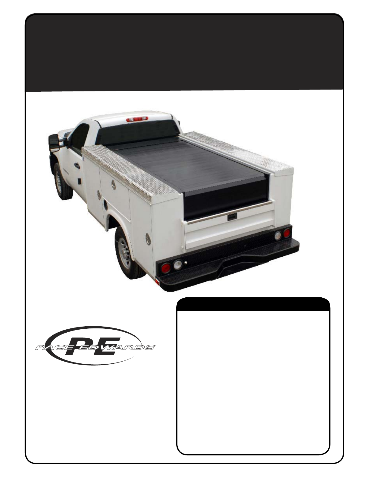
PACE EDWARDS
RETRACTABLE UTILITY
BED COVER - ELECTRIC
INSTALLATION INSTRUCTIONS
Pace Edwards Company
2400 Commercial Blvd.
Centralia WA 98531
(800) 338-3697 toll free
(360) 736-9991 main
(360) 736-9992 fax
www.paceedwards.com
Required Tools.............................................................. 2
Before You Start ........................................................... 2
Optional Wiring Harness .............................................. 2
Packaging Contents ..................................................... 2
Hardware Kit................................................................. 3
1. Place the Canister .................................................... 4
2. Installing the Horizontal Rails ................................ 4-5
3. Installing the Release System .................................. 5
4. Installing Drain Tubes............................................... 6
5. Install & Match Drill Horizontal rail clamps ............... 6
6. Shim the Horizontal rail clamps................................ 6
7. Bolt Down Horizontal rail clamps.............................. 7
8. Installing the Corner Blanket Guide.......................... 7
9. Installing Vertical Rails & clamps.............................. 8
10. Install the Wiring..................................................... 9
11. Connecting the Wires to the Battery ..................... 10
12. Mounting the Top Cover ....................................... 10
13. Lubricate the rails ................................................. 10
14 Installing the optional manual operation switch......11
Helpful Maintenance Hints ..........................................11
Warranty Statement.................................................... 12
TABLE OF CONTENTS
ERUBC INSTL 0711
TOOLS REQUIRED FOR ASSEMBLY:
Electric Drill
1/4” drill bit,
1/2” drill bit
9/32 Allen Wrench
7/16 Socket Wrench
Phillips screw Driver #1 & #2
Tape Measurer
Rubber mallet
BEFORE YOU START:
Read the instructions carefully before you start. If you have questions regarding the installation of your new Utility
Bedlocker™ retractable tonneau cover, please call our Technical Support Line at (800) 338-3697.
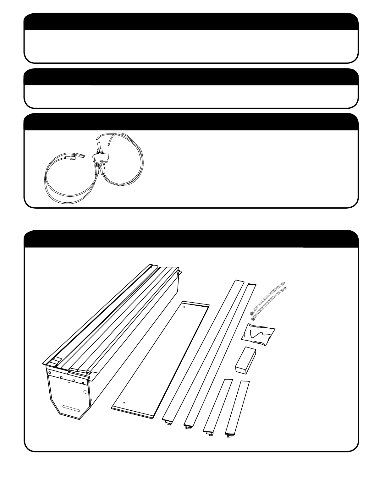
OPTIONAL WIRING HARNESS for dashboard switch.
The Utility BedLocker electric retractable tonneau cover also offers
an optional wire harness (part # BL1120) to manually operate the
tonneau cover from inside the cab of your truck. This harness is
designed to plug into the custom-built electronics control box. See
Page 8 for installation instructions.
PACKAGING CONTENTS:
CANISTER
STANDARD
HORIZONTAL
RAILS
TOP
COVER
DRAIN TUBES
HARDWARE KIT PACK
RAIL CLAMP PACK
STANDARD
VERTICAL RAILS
2 ELECTRIC UTILITY BED COVER INSTALLATION INSTRUCTIONS
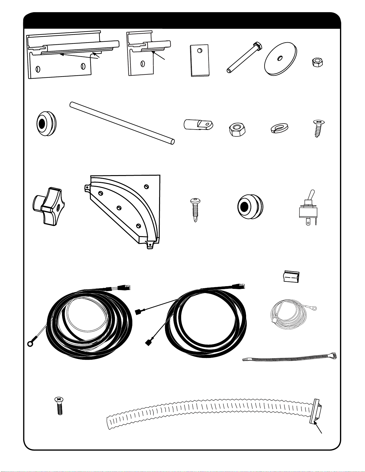
HARDWARE KIT:
FRONT CLAMP (x 1)
5/16x1/16x1/2
RUBBER
GROMMET (x 2)
4 ARM
KNOB (x 1)
SET
SCREWS
CORNER
CHANNEL
(x 2)
SCREW
CLAMP (x9)
w/ installed set
screws (x9)
THREADED
ROD (x 1)
SET
PLASTIC
SHIMS (x 37)
SWIVEL
COUPLER
(x 1)
#8 x ¾ PAN
SQUARE TEKSCREW (x 1)
¼-20 x 1¼
CLAMP
BOLT (x 11)
¼” X 20
HEX NUT
ZP (x 1)
FENDER
WASHER
(x 12)
¼” LOCK
WASHER
(x 1)
5/16x9/16x3/8x1/8
RUBBER
GROMMET (x 1)
¼ - 20
NYLOCK
(x 11)
#10 x ¾
SHEET
METAL
SCREW
(x 4)
CONTROL
SWITCH (x 1)
WIRE CLIPS (x 4)
BLACK GROUND
WIRE (x 1)
BATTERY WIRE
HARNESS (x 1)
#10-32 x ⅞ BLACK
TOP COVER SCREW
(x 2)
ELECTRIC UTILITY BED COVER INSTALLATION INSTRUCTIONS 3
CONTROL SWITCH WIRE
HARNESS (x 1)
DRAIN TUBE FITTING (x2)
WIRE TIES (x 6)
Foam Washer
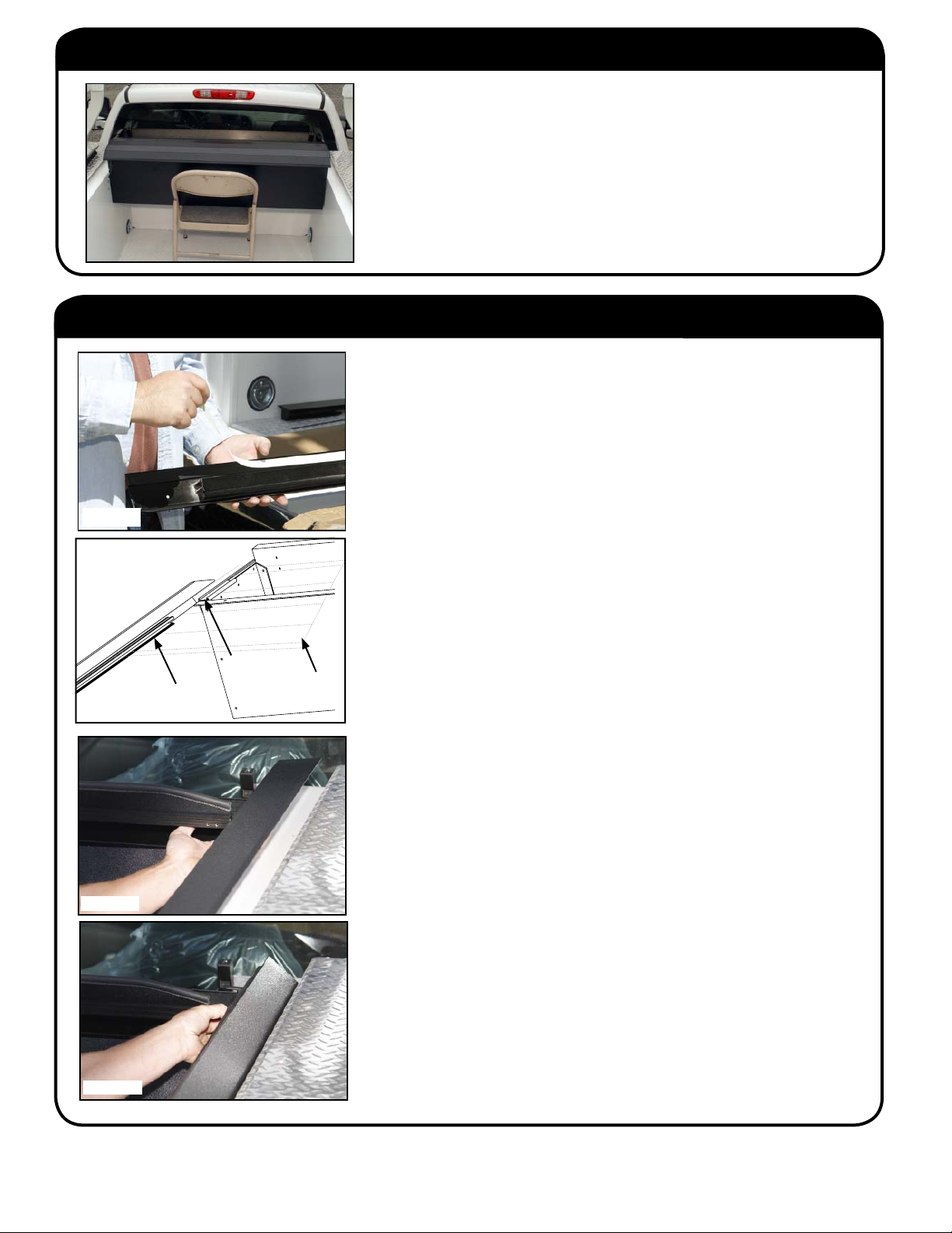
STEP 1. PLACE THE CANISTER
Prior to placing canister in the bed you will want to protect the paint
with a couple of towels or pieces of packing foam since the fi t is very
tight, there is a risk of scratching the sides of the bed. Blue painters
tape works well for protection also.
This will require two people. Set the canister on a stand at the front
end of the bed so that the sides of the canister are above the sides of
the truck bed about 3 inches. (A folding chair works well). (Fig. 1A)
Pull approximately 4-5 ribs of the cover out of the canister.
FIG. 1A
STEP 2. INSTALLING THE HORIZONTAL RAILS
The tailgate end of the rail can damage your box during installation;
we recommend wrapping the ends of the rails or protecting the
sides and top of box to prevent accidental damage.
Starting with either rail you will need to hold the rail level and slide the
lower rail (male profi le) into the rail grip (female profi le) that is bolted to
each side of the canister (Fig. 2A). You must hold the ribbed blanket out
and level while sliding the rail over it and into the rail grip on the canister.
(Make sure the ribbed blanket is correctly meshed on the gear).
FIG. 2A
FIG. 2B
FIG. 2C
FIG. 2D
Rail
Flange
Rail
Grips
Ribbed
Blanket
When properly inserted in the rail grips on the canister push the rails all
the way forward.
Once the rails are in place on both sides of the canister you can remove
the protection you placed on the bed and remove the stand the canister
was set on. Lowering the canister with rails attached onto the truck box.
The canister will fi t tight and need to be centered the truck bed.
Make sure the canister is centered in the truck bed at this point and
throughout this step.
(Flexing the rails inward prevents the clamps from scratching the
paint).
Install the rail clamps by fl exing the rails inward slightly, then slide rail
clamps in the order noted. (FIGURE 2E THE FORW ARD DRIVER SIDE
RAIL CLAMP IS WIDER AND HAS A NOTCH AT THE FRONT) Slide
one rail clamp all the way forward against the canister on both rails.
Make sure the wider notched driver side rail clamp is used on the driver
side and a regular narrow clamp is used on the passenger side. The gap
between the backside of the rail clamp and the side of the truck bed will
need to be shimmed.
To shim, move the rail clamp and place as many of the plastic shims
between the rail and the bed sidewall as needed to fi ll the gap. Place
the same number of shims on each side rail to maintain even centering.
When the rails are shimmed slide the clamps on the rails (Do not secure
clamp set screws yet).
With the front clamps shimmed you now need to install and shim the rail
clamps at the tailgate end the same way you did for the front. Measure
the width between the rails at the canister end and then at the tailgate
end. This width must not be wider at the tailgate than the canister end.
The width is best if shimmed 1/16th to 1/8th maximum narrower at the
tailgate end.
SAME FOR BOTH STANDARD
OR EXPLORER SERIES RAILS
4 ELECTRIC RETRACTABLE UTILITY BED COVER INSTALLATION INSTRUCTIONS

NOTCHED CLAMP 1 ONLY
USED OVER RELEASE ASSY.
EASE ASSY .
T
N
R
S
R
GROMMET
F
T
US
T
S
STEP 2. INSTALLING THE HORIZONTAL RAILS (CONT.)
FIG. 2E - DRIVERS SIDE RAIL CLAMP & COMPONENT ORDER
RAIL CLAMP
CORNER
CHANNEL
(Installed in step 4)
FORWARD
DRIVER SIDE
RAIL CLAMP
STEP 3: INSTALLING THE RELEASE SYSTEM
After the canister is in place measure out (canister to tailgate) 1-1/8” from face of canister and 21/32”(.650)
down from underside of canister lip drill a 9/16” hole in sidewall of box.
Insert rubber grommet.
Push threaded rod thru grommet until you can mate swivel coupler to release arm.
Install 6-32 bolt and nut. Tighten just enough that you let the two parts move freely. (Over tightening will
restrict movement of parts).
Move to inside of cabinet where you will install the large washer and Four Knob handle (fl at side of knob to
the outside).
Tighten just enough to keep the knob from spinning.
If you need to use the release just turn the knob until it disengages the cover. (Do not over tighten the knob
by forcing it). You will know when it’s at the end of stroke because you will feel it tightening down.
FOUR HANDLED KNOB
ELECTRIC RETRACTABLE UTILITY BED COVER INSTALLATION INSTRUCTIONS 5
1/8” SHIM
ED INSIDE CABINE
ENDER WASHER USED
INSIDE CABINE
HREADED ROD
UT & LOCK WASHE
WIVEL COUPLE

4. INSTALLING THE DRAIN TUBES
First ensure that the “o” ring is in place on the drain tube end being inserted into the canister. (This will prevent water
leakage)
With the cover opened, insert the drain tube fi ttings into the pre-drilled holes on the underside of the canister by
pushing them in place from
under the canister.
The drain tube should click into
place.
Route the end of the drain tubes
out any existing drain holes
present in the bed.
If no drain holes are provided
you will have to drill 2 - ¾” holes
that you can push the drain hose
through. (Make sure to touch
up any holes drilled to prevent
FIG. 4A
FIG. 4B
FIG. 4C
corrosion).
5. INSTALL AND MATCH DRILL THE HORIZONTAL RAIL CLAMPS
FIG. 5A
Make sure the canister is centered in the truck bed at this point and throughout this step.
(Flexing the rails inward prevents the clamps from scratching the paint).
Install the rail clamps by fl exing the rails inward slightly, then slide one rail clamp all the way forward against the
canister on both rails about 4”-6” from the canister. (Figure 5A) Tighten the set screw (Figure 5B) Do the same for
the Middle clamp (place midway between the two other clamps) and the End clamp (Place about an inch from the
corner channel) on both side rails (left and right).
Apply downward pressure to the rail and match drill the truck body with the hole in the the clamp. (Figure 5C)
FIG. 5B FIG. 5C
6. SHIM THE HORIZONTAL RAIL CLAMPS (IF NEEDED)
FIG. 6A
Measure between the rails to determine the need for shims. (Figure 6A)
The gap between the backside of the rail clamp and the side of the truck bed will need to be shimmed. Remove
the paper backing to expose the sticky side of the shim. (Figure 6B)
To shim, move the rail clamp and place as many of the plastic shims between the rail and the bed sidewall as
needed to fi ll the gap. (Figure 6C) Place the same number of shims on each side rail to maintain even centering.
FIG. 6B
FIG. 6C
6 ELECTRIC RETRACTABLE UTILITY BED COVER INSTALLATION INSTRUCTIONS

7. BOLT DOWN HORIZONTAL RAIL CLAMPS
Fig. 7B Fig. 7A
With the rails shimmed properly
Measure the width between the rails at the canister end and then at the tailgate end. This width must not be
wider at the tailgate than the canister end. The width is best if shimmed 1/16th to 1/8th maximum narrower at the
tailgate end.
With a partner on the outside of the truck to help, use the ¼-20x 1¼ Clamp Bolt, Fender washer, and ¼-20 nylock
washer to secure all the clamps to the truck body. (Figure 7A & 7B)
8. INSTALLING CORNER BLANKET GUIDE
The Corner Channel must be shimmed, using the plastic shims provided, the same as the rails so that it is fl ush with
the inside of the rails.
It is essential that the horizontal and vertical rails are evenly spaced from side to side and square from front
to rear by measuring and making sure all measurements are the same.
Attach the corner channel to the horizontal rail with the 2 - 10 x ¾ BLACK SHEET METAL SCREW. (Figure 8A)
Attach the corner blanket guide the the vertcal rail with the 2- 10 x ¾ BLACK SHEET METAL SCREW. (Figure 8B)
FIG. 4B
FIG. 4AFIG. 4A
Fig. 8A
Fig. 8B
ELECTRIC RETRACTABLE UTILITY BED COVER INSTALLATION INSTRUCTIONS 7

9. INSTALL VERTICAL RAIL CLAMPS
Temporarily remove the end cap screws. (Figure 9A)
Slide the clamps on the vertical rail and secure into place with
the allen wrench and set screw. (Figures 9B & 9C)
Match Drill the Vertical Rail clamps to the truck body. (Figure
9D)
Add shims as needed then secure the vertical rail clamps with
your partner on one side you on the other. (Figure 9E)
Secure the Vertical rail stop strip to the corner blanket guide.
with the #6-32-⅜ STOP STRIP CORNER SCREW (Figure
Fig. 9A
9F)
Reinstall the end cap screws in both sides. (Figure 9A)
Fig. 9B
Fig. 9D
Fig. 9C
Fig. 9E
Fig. 9F
8 ELECTRIC RETRACTABLE UTILITY BED COVER INSTALLATION INSTRUCTIONS

10. INSTALL THE WIRING
In the drivers side forward cabinet drill a ½” hole thru the sidewall of bed box about 1 inch in front of and level with
the wiring exit hole in the retractable bed cover canister. (Fig. 10A)
Deburr the hole on both sides of the cabinet wall and push wires from canister into cabinet.
Slice through the rubber grommet and wrap it around the wire harness. Work the grommet into the ½” hole and
pull the wire harness through to eliminate most of the slack. (Fig. 10B)
In the forward drivers cabinet, plug the wires together from the Canister Wire Harness to the Electronics Control
Box
The wires are staggered in length to ease installation through the cabinet wall, plug the wires together by color.
Fig. 10A Fig. 10B
Plug the Control Switch Wire Harness into the 2-wire plug (Without the rubber cover) (Purple/ Green).
Route the wire harness back to the tailgate end, rear cabinet area using any existing openings that are
available.
You may need to drill between the cabinets for wire harness routing.
Use the wire clips and wire ties provided by peeling the double back tape and sticking it in place to position the
wire harness as needed.
Secure the wire harness with zip ties.
Determine where you want to mount the Control Switch and drill a ½” hole (Deburr hole on both sides of cabinet
wall).
Mount the Control Switch.
Attach the black ground wire to the center post on the Control Switch and drill or attach ring connector to a ground
(using the #8 3/4 pan square tek screw) Figure 10D.
Plug the Grey and Purple wires to the other 2 posts
(If the switch operates the cover the opposite direction that you prefer, you only need to switch the Grey
and Purple wires to correct it)
Fig. 10C
ELECTRIC RETRACTABLE UTILITY BED COVER INSTALLATION INSTRUCTIONS 9
Fig. 10D

11. CONNECTING THE WIRES TO THE BATTERY
Plug the green and blue 2-wire battery harness into the control
box.
Drill a ½” hole in the bottom of the drivers side forward cabinet,
preferably in the forward innermost corner to keep the battery
wire harness neatly tucked out of the way (Fig. 11A)
Hole positions and wire harness routing will vary between
box manufactures and models.
Deburr the ½” hole on both sides of the cabinet.
Push wire harness through the hole.
Slice the rubber grommet, wrap around the harness and work
into the hole to protect the wiring from the metal.
(The Optional Manual Operation Switch should be routed at
the same time as the battery harness).
Route this wire harness along the frame and up into the battery
compartment.
Attach the wire harness using wire ties provided (keep away from hot surfaces).
Attach Red (+) wire to positive 12V battery block and the Black (–) to appropriate ground.
(Ring connectors provided may need to be cut down or replaced due to bolt and attachment variations found on
different vehicles.
Coil excess wiring and secure with a wire tie in the engine compartment.
Your Utility Bedlocker cover should run at this time. Check for correct operation by operating all switches
installed.
Fig. 11A
12. INSTALL THE TOP COVER
Install the top cover on the canister making sure it is fl ush with the horizontal rail. Use the 2-Black Top Cover
Screws.
13. LUBRICATE THE RAILS
Use the included 303 protectant to lubricate the sweep seal
and wear strip. This ensures the cover glides smoothly the
fi rst time it is very important to lubricate the seals on the rails.
You will need to periodically lubricate these seals throughout
the life of the cover. We recommend using the 303 Brand
protectant.
10 ELECTRIC RETACTABLE UTILITY BED COVER INSTALLATION INSTRUCTIONS

14. INSTALLING THE OPTIONAL MANUAL OPERATION SWITCH
Route the (Optional) Manual Operation Switch wiring through the fi rewall of the truck and pull the harness into
the cab.
Coil the excess wire harness and tie out of the way.
Drill and mount the switch bracket at a convenient position under the dash.
Snap the rocker switch into the switch bracket.
Place ground wire onto center post of rocker switch and attach opposite end to a ground.
Crimp the female spade connectors to the Grey and Purple wires.
Attach the crimped wire to the remaining switch posts.
(If cover runs in opposite direction than you prefer, just switch the Grey and Purple wires).
Your Utility Bed Cover should run at this time. Check for correct operation by operating all switches installed.
(Part #
BL1120)
HELPFUL MAINTENANCE HINTS
To assure quiet, smooth operation, apply a small amount of grease to the guide strips where the metal end of
the panels and the guide strips meet. This initial application should be suffi cient for a year or more. Regrease the
guide strips if the cover begins squeaking during use.
Drain tubes may become clogged over time and should be removed and cleaned.
Periodically remove the top cover and clean out the canister.
To help keep the tonneau cover looking its best, we recommend washing it the same as caring for your truck
fi nish.
If you have any questions please call our Technical Support at (800) 338-3697.
ELECTRIC RETRACTABLE UTILITY BED COVER INSTALLATION INSTRUCTIONS 11

CONGRATULATIONS!
On your purchase of a Pace Edwards Retractable Truck Bed Cover.
We are confi dent that you will get many years of trouble free service from this accessory to your truck. Please take a moment to fi ll out the
warranty registration form to activate warranty coverage of your truck bed cover.
PACE EDWARDS PRODUCT WARRANTY
PACE EDWARDS (hereinafter referred to as the MFG.) warrants each new Pace Edwards
Bedlocker®, JackRabbit®, Full-Metal-JackRabbit™, and Roll-Top-Cover® retractable
truck bed cover to the original owner as follows:
FOR A PERIOD OF THREE (3) YEARS FROM THE DATE THE UNIT IS DELIVERED TO THE FIRST
PURCHASER OR PLACED INTO SERVICE AS A DEMONSTRATOR OR COMPANY UNIT:
• Delamination of the ArmorTek deck
• Separation of the Bedlocker/Full Metal deck panels
• Failure of the Continuous Tension Spring
• Failure of the Bedlocker drive system
• All lock assemblies
• All hardware and components
ITEMS NOT COVERED UNDER WARRANTY FOR ANY PERIOD OF TIME:
• Rips, tears, or discoloration of the ArmorTek deck material
• Seals and gaskets
• Water intrusion from any source
• Dealer and/or purchaser installed parts and accessories
CERTAIN CONDITIONS WILL VOID ALL WARRANTY.
These conditions include:
• Use for any purpose other than normal private use including rental and
promotion
• Altering the retractable truck bed cover in any manner without written approval of
the MFG
• Misuse, negligence or accident
• Installation of any part or accessory without written approval from the MFG
• Failure to register this warranty with the MFG within fourteen (14) days from date
of delivery
CLAIM PROCEDURE
If a part fails, the purchaser should return to the selling dealer to determine if the failed part is covered under the terms of this warranty. If a Warranty Claim is necessary, the dealer will
contact Pace Edwards to obtain A Return Goods Authorization. If it is impractical for the purchaser to return to the selling dealer, then the purchaser may contact the Pace Edwards Technical
Assistance Help Desk at 1-800-338-3697 to determine warranty eligibility. In either event, it is the responsibility of the purchaser to obtain a Return Goods Authorization prior to returning
the defective part to the MFG. The defective part, along with a copy of the original Bill of Sale and the Pace Edwards issued RGA #, must be returned PREPAID to Pace Edwards Co. 2400
Commercial Blvd. Centralia, WA 98531. After determining the validity of the warranty claim, PACE EDWARDS will ship a replacement part prepaid to the customer. Labor costs to replace
defective parts are the responsibility of the purchaser.
CONDITIONS AND LIMITATIONS
This warranty is subject to certain conditions and limitations including, but not limited to,
the following:
• Any part of a Pace Edwards retractable truck bed cover that is found to be defective
under the terms of this warranty will be repaired or replaced using either new or
reconditioned parts at the discretion of the MFG.
• In determining what constitutes a failure under the terms of this warranty the
decision of the MFG shall be fi nal.
• This warranty is extended to the original purchaser only and is not transferable to
subsequent purchasers.
• The MFG does not accept any responsibility in connection with the installation of
any of its products by its dealers or agents.
• The MFG does not undertake responsibility to any purchaser for warranty express
or implied by any of its dealers, distributors or agents beyond that which is
contained herein.
• Without regard to an alleged defect of its products the MFG under any circumstances
does not assume responsibility for loss of time, inconvenience, revenue, or other
consequential damage including, but not limited to, expenses for telephone, food,
lodging, travel, loss or damage to the vehicle the products are installed on or loss
or damage to personal property of the purchaser or user of the products.
• The MFG reserves the right to make changes in the design of, improvements to, or
warranty of its products without imposing any obligation upon itself to provide the
same for any products theretofore manufactured.
Some jurisdictions do not allow limitations on or exclusions to warranties, therefore some of the
exclusions may not apply to you. This warranty affords you specifi c legal rights. You may have
other legal rights that may vary from jurisdiction to jurisdiction.
WARRANTY REGISTRATION
Please return this completed warranty registration within 14-days to:
Or go online and register your warranty at:
http://www.pace-edwards.com/Warranty-Care
NAME:
ADDRESS:
CITY: PROV./STATE: PC/ZIP:
MODEL #: SERIAL #:
DATE OF PURCHASE: PURCHASED FROM: PRICE PAID:
CUSTOMER SIGNATURE:
Pace Edwards
Attn: Warranty Dept.
2400 Commercial Blvd.
Centralia, WA 98531
 Loading...